DE202008009817U1 - Blackboard, especially presentation board - Google Patents
Blackboard, especially presentation board Download PDFInfo
- Publication number
- DE202008009817U1 DE202008009817U1 DE200820009817 DE202008009817U DE202008009817U1 DE 202008009817 U1 DE202008009817 U1 DE 202008009817U1 DE 200820009817 DE200820009817 DE 200820009817 DE 202008009817 U DE202008009817 U DE 202008009817U DE 202008009817 U1 DE202008009817 U1 DE 202008009817U1
- Authority
- DE
- Germany
- Prior art keywords
- board
- panel
- profile
- segments
- feet
- Prior art date
- Legal status (The legal status is an assumption and is not a legal conclusion. Google has not performed a legal analysis and makes no representation as to the accuracy of the status listed.)
- Expired - Lifetime
Links
- 210000002105 tongue Anatomy 0.000 description 9
- 239000000463 material Substances 0.000 description 2
- 150000001768 cations Chemical class 0.000 description 1
- 239000007799 cork Substances 0.000 description 1
- 210000003746 feather Anatomy 0.000 description 1
Classifications
-
- A—HUMAN NECESSITIES
- A47—FURNITURE; DOMESTIC ARTICLES OR APPLIANCES; COFFEE MILLS; SPICE MILLS; SUCTION CLEANERS IN GENERAL
- A47B—TABLES; DESKS; OFFICE FURNITURE; CABINETS; DRAWERS; GENERAL DETAILS OF FURNITURE
- A47B97/00—Furniture or accessories for furniture, not provided for in other groups of this subclass
-
- B—PERFORMING OPERATIONS; TRANSPORTING
- B43—WRITING OR DRAWING IMPLEMENTS; BUREAU ACCESSORIES
- B43L—ARTICLES FOR WRITING OR DRAWING UPON; WRITING OR DRAWING AIDS; ACCESSORIES FOR WRITING OR DRAWING
- B43L1/00—Repeatedly-usable boards or tablets for writing or drawing
-
- G—PHYSICS
- G09—EDUCATION; CRYPTOGRAPHY; DISPLAY; ADVERTISING; SEALS
- G09F—DISPLAYING; ADVERTISING; SIGNS; LABELS OR NAME-PLATES; SEALS
- G09F15/00—Boards, hoardings, pillars, or like structures for notices, placards, posters, or the like
- G09F15/0068—Modular articulated structures, e.g. stands, and articulation means therefor
Landscapes
- Physics & Mathematics (AREA)
- General Physics & Mathematics (AREA)
- Engineering & Computer Science (AREA)
- Theoretical Computer Science (AREA)
- Drawing Aids And Blackboards (AREA)
Abstract
Tafel, insbesondere Moderationstafel, mit mindestens zwei Tafelsegmenten, die jeweils auf jeder Seite eine Profilhohlleiste aufweisen, von denen die Profilhohlleisten von aneinander grenzenden Tafelsegmenten über ein Gelenk miteinander verbunden sind, wobei in einem zusammengeklappten Zustand die Tafelsegmente flächig aufeinander angeordnet sind und in einem entklappten Zustand gemeinsam eine einheitliche Tafelfläche bilden, und wobei mindestens ein Band wenigstens teilweise in zwei aneinander grenzenden Profilhohlleisten verläuft und die Profilhohlleiste eines ersten Tafelsegments mit der angrenzenden Profilhohlleiste eines zweiten Tafelsegments verbindet.Blackboard, in particular a presentation board, with at least two board segments, each having on each side a profile rail, from the profile hollow strips of adjacent panel segments over a Joint are interconnected, being in a folded Condition the board segments flat are arranged on top of each other and in an unfolded state in common a uniform board surface form and at least one band at least partially in two adjacent profile hollow strips runs and the profile rail a first board segment with the adjacent profile rail a second panel segment connects.
Description
Die vorliegende Erfindung betrifft eine Tafel, insbesondere eine Moderationstafel.The The present invention relates to a panel, in particular a presentation panel.
Moderationstafeln werden gelegentlich auch als Boards, Planungstafeln, Präsentationstafeln oder -boards, Pintafeln oder Magnettafeln bezeichnet.Presentation boards Occasionally also as boards, planning boards, presentation boards or boards, pinboards or magnetic boards.
Moderationstafeln besitzen in der Regel eine ebene Tafelfläche, die mit einem Ständer verbunden ist, dessen unteres Ende in Füßen mündet, auf denen der Ständer steht. Für Moderationstafeln sind zahlreiche unterschiedliche Ausgestaltungen bekannt. So kann beispielsweise die Moderationstafel in mehrere Tafelsegmente aufgeteilt sein, der Ständer einstückig mit der Moderationstafel über eine Profilleiste ausgebildet sein oder separat an die Tafel angesetzt sein. Unabhängig von der konkreten Ausgestaltung der Moderationstafel hat es sich für viele Anwen dungszwecke von Moderationstafeln als nachteilig herausgestellt, dass diese recht sperrig sind.Presentation boards usually have a flat board surface that is connected to a stand, whose lower end opens into feet those of the stand stands. For Moderation boards are numerous different designs known. For example, the presentation board can be divided into several Board segments to be divided, the stand in one piece with the presentation board on a profile strip be formed or attached separately to the board. Independent of The concrete design of the presentation board, it has for many appli cation purposes of Moderationstafeln as disadvantageous that this quite bulky.
Der Erfindung liegt die Aufgabe zugrunde, eine Moderationstafel bereitzustellen, die einerseits stabil steht und andererseits nach dem Gebrauch sich gut transportieren und/oder verstauen lässt.Of the The invention has the object of providing a presentation board, on the one hand stable and on the other hand after use itself transport and / or stow well.
Erfindungsgemäß wird die Aufgabe durch eine Tafel mit den Merkmalen aus Ansprüchen 1 und 10 gelöst.According to the invention Task by a panel having the features of claims 1 and 10 solved.
Die erfindungsgemäße Tafel besitzt mindestens zwei Tafelsegmente, die seitlich ein Paar von Profilhohlleisten aufweisen. Bevorzugt besitzt die erfindungsgemäße Tafel drei Tafelsegmente. Die Profilhohlleisten der Tafelsegmente sind über ein Gelenk miteinander verbunden, wobei in einem zusammengeklappten Zustand die Tafelsegmente flächig aufeinander angeordnet sind und in einem entklappten Zustand gemeinsam eine einheitliche Tafelfläche bilden. In den Profilhohlleisten verläuft erfindungsgemäß mindestens ein Band, das die Profilhohlleiste eines ersten Tafelsegments mit einer Profilhohlleiste eines zweiten Tafelsegments verbindet. Das Gelenk, das ebenfalls zwei einander angrenzende Tafelsegmente bzw. deren Profilhohlleisten miteinander verbindet, dient ebenfalls dazu, aneinander grenzende Profilhohlleisten klappbar miteinander zu verbinden. Die erfindungsgemäße Tafel besitzt den Vorteil, dass über das Gelenk und das Band zwischen den Tafelsegmenten die Tafel zusammengeklappt werden kann, wodurch ihre Flachseite nur die Größe eines der Tafelsegmente besitzt. Die zusammengeklappte Tafel kann daher besonders gut transportiert werden und benötigt auch bei ihrer Lagerung nur wenig Raum.The inventive panel has at least two panel segments, the side a pair of profile strips exhibit. The panel according to the invention preferably has three panel segments. The profile hollow strips of the panel segments are connected by a joint connected, wherein in a folded state, the panel segments flat are arranged on top of each other and in an unfolded state in common a uniform board surface form. In the profile strips runs according to the invention at least a band containing the profile hollow bar of a first panel segment a profile hollow bar of a second panel segment connects. The Joint, which also has two adjacent panel segments or whose profile strips connect with each other also serves to adjoining profile hollow strips hinged together to connect. The inventive panel has the advantage of being over the hinge and the band folded between the panel segments the panel can be, making their flat side just the size of one of the panel segments has. The folded panel can therefore be transported particularly well be and needed even when stored little space.
In einer bevorzugten Ausgestaltung der erfindungsgemäßen Tafel ist das Band elastisch ausgebildet, wobei sich im zusammengeklappten Zustand des ersten und zweiten Tafelsegments das Band in seiner Länge dehnt, d. h. die Länge des elastischen Bandes wird durch das Zusammenklappen vergrößert, so dass das elastische Band eine Kraft ausübt. Alternativ oder zusätzlich ist es möglich, das Band über Federmittel mit der Profilhohlleiste der Tafelsegmente zu verbinden, wobei dann im zusammengeklappten Zustand der Tafelsegmente die Federmittel durch das Band gedehnt werden und so eine Kraft ausüben. Es ist selbstverständlich auch möglich, ein elastisches Band über Federmittel in der Profilhohlleiste anzubinden. Durch die Dehnung des elastischen Bandes und/oder der Federmittel wird beim Zusammenklappen der Tafelsegmente eine Kraft ausgeübt, gegen die die Zusammenklappbewegung erfolgt. Auf diese Weise ist es möglich, die Tafelsegmente kontrolliert zusammenzuklappen, ohne dass eine Situation entsteht, in der die Tafelsegmente unkontrolliert zusammenfallen.In a preferred embodiment of the panel according to the invention the band is elastically formed, being in the folded Condition of the first and second panel segment the band in his Length stretches, d. H. the length the elastic band is enlarged by the folding, so that the elastic band exerts a force. Alternatively or additionally it is possible the tape over To connect spring means to the profile rail of the panel segments, wherein then in the folded state of the panel segments, the spring means be stretched by the band and thus exercise a force. It is self-evident also possible, an elastic band over To connect spring means in the profile rail. By stretching the elastic band and / or the spring means is folded when folding the panel segments exerted a force against which the collapsing movement he follows. In this way it is possible to control the panel segments collapse without creating a situation in which the Board segments collapse uncontrollably.
In einer bevorzugten Ausgestaltung ist das Gelenk stirnseitig zwischen zwei Profilhohlleisten gesetzt, wobei das Gelenk jeweils zwei auf die Profilhohlleisten aufgesetzte Endkappen besitzt. Jede der Endkappen hält eine Scharnierzunge, die aus der Endkappe vorsteht.In a preferred embodiment, the joint is the front side between set two profile strips, the joint each two on the profile hollow strips has patch end caps. Each of the end caps holds one Hinge tongue protruding from the end cap.
In einer bevorzugten Ausgestaltung besitzt das Gelenk eine erste Scharnierzunge mit einem vorstehenden Stift und eine zweite Scharnierszunge, die eine Öse zur Aufnahme des Stifts aufweist. Um die Tafelsegmente im zusammengeklappten Zustand flächig aneinander in Anlage zu bringen, ist der Stift der Scharnierzunge quer zur Längsrichtung der Profilhohlleiste angeordnet.In In a preferred embodiment, the hinge has a first hinge tongue with a protruding pin and a second hinge tongue, which has an eyelet for receiving of the pen. To the panel segments in the folded Condition flat abutting each other is the pin of the hinge tongue transverse to the longitudinal direction arranged the profile rail.
In einer weiteren bevorzugten Ausgestaltung ist für mindestens ein Gelenk zwischen zwei Tafelsegmenten zusätzlich eine Verriegelungseinrichtung vorgesehen. Die Verriegelungseinrichtung weist einen in einer der Profilhohlleisten geführten Riegel auf, der in seiner vorgeschobenen Position in die angrenzende Profilhohlleiste eintritt. In seiner vorgeschobenen Position erstreckt sich der Riegel durch zwei über das Gelenk verbundene Profilhohlleisten, so dass diese eine starre Einheit bilden. In seiner zurückgeschobenen Position ist der Riegel nahezu vollständig in einer der Profilhohlleisten angeordnet, so dass zwei benachbarte Tafelsegmente gegeneinander klappbar sind.In Another preferred embodiment is for at least one joint between two board segments in addition provided a locking device. The locking device has a guided in one of the profile hollow bars on which in his advanced position enters the adjacent profile rail. In its extended position, the latch extends through two over the Articulated profile strips, so that these are a rigid unit form. In his retarded Position the latch is almost completely in one of the profile strips arranged so that two adjacent panel segments against each other are foldable.
In einer zweckmäßigen Ausgestaltung weist der Riegel eine Feder auf, die den Riegel in seiner zurückgeschobenen Position und/oder in seiner vorgeschobenen Position in seiner Profilhohlleiste hält. Die Feder stellt sicher, dass der Riegel eine definierte Position relativ zu den Profilhohlleisten einnehmen kann und somit stets festgelegt ist, ob die Tafelsegmente gegeneinander verriegelt sind oder nicht.In an expedient embodiment, the latch on a spring that holds the latch in its retracted position and / or in its advanced position in its profile rail. The spring ensures that the bolt can assume a defined position relative to the profile hollow strips and thus is always determined whether the Tafelseg are locked against each other or not.
In einer weiteren bevorzugten Ausgestaltung weist der Riegel einen Knopf auf, der seitlich aus der Profilhohlleiste vorsteht. Der Knopf dient dazu, den Riegel in die gewünschte Position zu schieben.In In another preferred embodiment, the bolt has a Button on, which projects laterally from the profile rail. The button serves to push the latch to the desired position.
Die erfindungsgemäße Aufgabe wird ebenfalls durch eine Tafel mit den Merkmalen aus Anspruch 10 gelöst.The inventive task is also by a panel having the features of claim 10 solved.
Die erfindungsgemäße Tafel besitzt seitlich jeweils ein Paar von Füßen, die in einem ausgeklappten Zustand der Füße bezogen auf die Flachseite der Tafel nach vorne und hinten abstehen und die in einem zusammengeklappten Zustand parallel zur Flachseite der Tafel verlaufen. Die erfindungsgemäße Tafel besitzt zwei Paare von Füßen, die seitlich von der Tafel angeordnet sind und diese in ihrer aufrechten Position halten. Die Füße, welche nach vorne und hinten von der Tafel vorstehen, nehmen beim Transport oder bei der Lagerung der Tafel wenig Platz ein. Mit den erfindungsgemäß zusammenklappbaren Füßen können diese im zusammengeklappten Zustand parallel zur Flachseite der Tafel gebracht werden, wodurch diese Tafel sich besser lagern und transportieren lässt.The inventive panel has laterally each a pair of feet, which in an unfolded Condition of the feet related stand out on the flat side of the board to the front and back and in a folded state parallel to the flat side the blackboard. The panel according to the invention has two pairs of feet that are arranged laterally from the board and these in their upright Hold position. The feet, which project forward and backward from the board, take in transit or in the storage of the panel little space. Collapsible with the invention Feet can do this in the folded state parallel to the flat side of the panel be brought, whereby this panel store better and transport leaves.
In einer bevorzugten Ausgestaltung der zusammenklappbaren Tafel sind sowohl Tafelsegmente gegeneinander klappbar als auch die Füße der Tafel zusammenklappbar.In a preferred embodiment of the collapsible panel are both panel segments against each other foldable and the feet of the panel collapsible.
In einer bevorzugten Ausgestaltung weisen die Füße eines Fußpaares jeweils an ihren zueinander weisenden Enden jeweils ineinander kämmende Zahnkränze auf, die derart angeordnet sind, dass eine Bewegung eines Fußes den anderen Fuß mitnimmt. Zum Zusammenklappen eines Fußpaares ist es also nur erforderlich, einen Fuß zu erfassen und in die zusammengeklappte Position zu bringen. Über den Zahnkranz wird der gegenüberliegende Fuß bei dieser Bewegung mitgenommen und ebenfalls in die gewünschte Position gebracht. Indem die Bewegung der Füße eines Fußpaares miteinander gekoppelt ist, wird sichergestellt, dass stets beide Füße eines Fußpaares ausgeklappt sind. So kann vermieden werden, dass versehentlich lediglich ein Fuß eines Fußpaares ausgeklappt wird und die Tafel zur Seite fällt.In In a preferred embodiment, the feet of a pair of feet each at their pointing ends each intermeshing sprockets, which are arranged such that a movement of a foot the takes another foot. For folding a foot pair So it is only necessary to grasp one foot and fold it into one Position. On the Sprocket is the opposite Walk with this Movement taken and also brought into the desired position. By doing the movement of one's feet pair of feet coupled with each other, ensures that both are always Feet of one pair of feet are unfolded. This can be avoided accidentally only a foot of one pair of feet is unfolded and the panel falls to the side.
In einer zweckmäßigen Ausgestaltung ist jeder Fuß eines Fußpaares über eine Schraube drehbar in einer am unteren Ende der Profilhohlleiste verlaufenden Querleiste gelagert.In an expedient embodiment every foot is one Foot pair over one Screw rotatable in a running at the bottom of the profile rail Rail mounted.
Die Erfindung wird nachfolgend anhand eines Ausführungsbeispiels näher erläutert. Es zeigt:The Invention will be explained in more detail with reference to an embodiment. It shows:
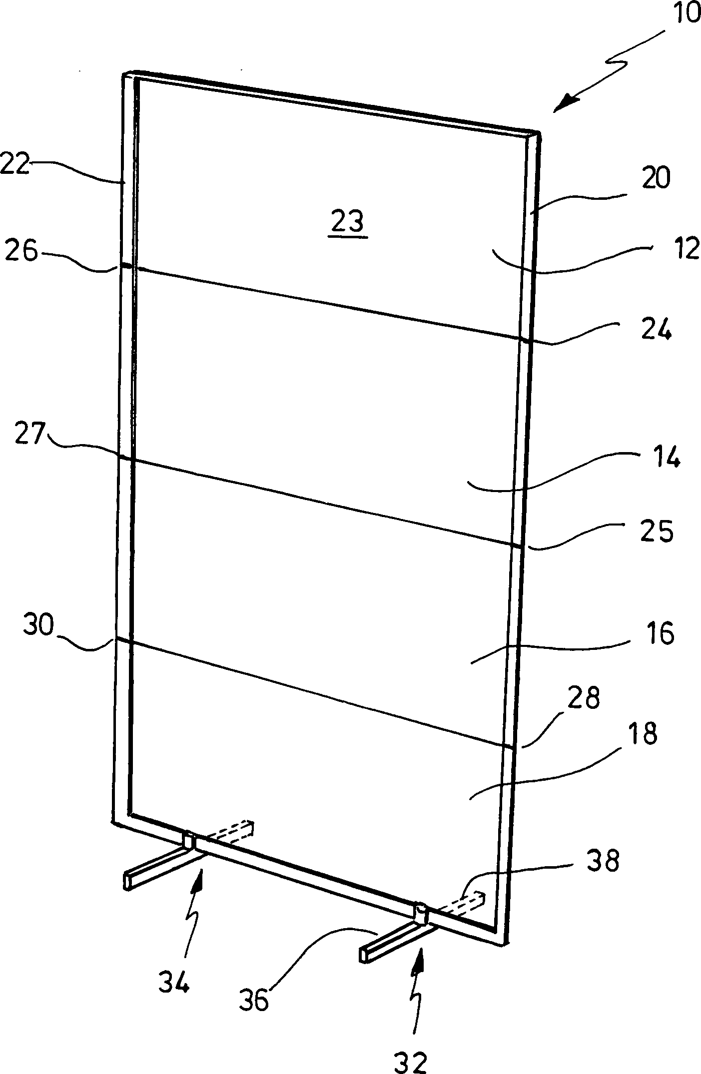
In
den Profilhohlleisten
Auf
dem Endabschnitt der Profilhohlleisten ist jeweils eine Endkappe
Ferner
ist in
Während in
der in
Claims (13)
Priority Applications (1)
| Application Number | Priority Date | Filing Date | Title |
|---|---|---|---|
| DE200820009817 DE202008009817U1 (en) | 2008-07-21 | 2008-07-21 | Blackboard, especially presentation board |
Applications Claiming Priority (1)
| Application Number | Priority Date | Filing Date | Title |
|---|---|---|---|
| DE200820009817 DE202008009817U1 (en) | 2008-07-21 | 2008-07-21 | Blackboard, especially presentation board |
Publications (1)
| Publication Number | Publication Date |
|---|---|
| DE202008009817U1 true DE202008009817U1 (en) | 2008-12-24 |
Family
ID=40157818
Family Applications (1)
| Application Number | Title | Priority Date | Filing Date |
|---|---|---|---|
| DE200820009817 Expired - Lifetime DE202008009817U1 (en) | 2008-07-21 | 2008-07-21 | Blackboard, especially presentation board |
Country Status (1)
| Country | Link |
|---|---|
| DE (1) | DE202008009817U1 (en) |
Cited By (3)
| Publication number | Priority date | Publication date | Assignee | Title |
|---|---|---|---|---|
| GB2469818A (en) * | 2009-04-28 | 2010-11-03 | Imaging Business Beaconsfield | Collapsible, foldable display apparatus with magnetic attachment means. |
| DE102011003083A1 (en) | 2011-01-25 | 2011-11-17 | Franken Planungs- Und Organisationsmittel Gmbh | Tripod has blackboard with regulating unit, with which width of tripod is adjusted, where length-variable rod is formed as regulating unit |
| DE102010063157A1 (en) | 2010-12-15 | 2011-12-01 | Franken Planungs- Und Organisationsmittel Gmbh | Presentation board, has foot elements, support leg and/or sliding connectors connected with board by sliding connection and optionally by snap connection or by arresting knob, and arresting device for blocking sliding connection |
-
2008
- 2008-07-21 DE DE200820009817 patent/DE202008009817U1/en not_active Expired - Lifetime
Cited By (4)
| Publication number | Priority date | Publication date | Assignee | Title |
|---|---|---|---|---|
| GB2469818A (en) * | 2009-04-28 | 2010-11-03 | Imaging Business Beaconsfield | Collapsible, foldable display apparatus with magnetic attachment means. |
| DE102010063157A1 (en) | 2010-12-15 | 2011-12-01 | Franken Planungs- Und Organisationsmittel Gmbh | Presentation board, has foot elements, support leg and/or sliding connectors connected with board by sliding connection and optionally by snap connection or by arresting knob, and arresting device for blocking sliding connection |
| DE102010063157B4 (en) | 2010-12-15 | 2023-07-27 | Franken Planungs- Und Organisationsmittel Gmbh | Presentation board with lock to slide in and lock the feet |
| DE102011003083A1 (en) | 2011-01-25 | 2011-11-17 | Franken Planungs- Und Organisationsmittel Gmbh | Tripod has blackboard with regulating unit, with which width of tripod is adjusted, where length-variable rod is formed as regulating unit |
Similar Documents
| Publication | Publication Date | Title |
|---|---|---|
| DE69601773T2 (en) | Detachable presentation device for a poster | |
| DE102018119822B4 (en) | FOLDABLE BOWL SYSTEM AND PROCEDURE FOR MOVING A BOWL SECTION | |
| EP0114407A2 (en) | Writing utensil with two writing points | |
| EP1554184A2 (en) | Foldable frame | |
| DE102007008951A1 (en) | Collapsible table used for playing table tennis, has supporting structure including vertical leg with sliding guide section which can be locked in either of two positions | |
| DE202008009284U1 (en) | Structural system | |
| AT523270B1 (en) | Arrangement for guiding a sliding door or folding sliding door | |
| EP2623348B1 (en) | Wind deflector with additional joints | |
| DE2003027A1 (en) | Floor mat for gymnastic and other sporting purposes | |
| DE102013209811B4 (en) | Folding ball cart with minimized volume | |
| DE202008009817U1 (en) | Blackboard, especially presentation board | |
| DE2711618A1 (en) | STRETCH FRAME FOR DECORATIVE FABRICS, CANVAS OR THE LIKE USED AS A MURAL | |
| DE102013107139A1 (en) | Device and method for folding a stroller by a sliding movement | |
| AT9832U1 (en) | TRANSPORT CONTAINER | |
| DE10062425B4 (en) | Collapsible floor trolley | |
| DE102015200887A1 (en) | Stroller frame | |
| DE4403687A1 (en) | Linking hinge for endface connection of two plates | |
| DE102004018589A1 (en) | Closure device for a bag | |
| DE60010832T2 (en) | Table style which is provided with at least one foldable foot or base frame | |
| EP0960776B1 (en) | Foldable warning triangle | |
| DE19520611C1 (en) | Foldable carrycot, playpen or similar | |
| AT519877B1 (en) | Leporellobuch | |
| DE69907413T2 (en) | MECHANISM TO LOCK AT THE HEIGHT OF AN IRONING TABLE | |
| DE3830154A1 (en) | Apparatus for collecting and storing balls, in particular tennis balls | |
| DE19734126C2 (en) | Cuboid container |
Legal Events
| Date | Code | Title | Description |
|---|---|---|---|
| R207 | Utility model specification |
Effective date: 20090129 |
|
| R150 | Term of protection extended to 6 years | ||
| R150 | Term of protection extended to 6 years |
Effective date: 20111130 |
|
| R151 | Term of protection extended to 8 years | ||
| R151 | Term of protection extended to 8 years |
Effective date: 20140922 |
|
| R152 | Term of protection extended to 10 years | ||
| R071 | Expiry of right |