DE202008009811U1 - Heat exchanger - Google Patents
Heat exchanger Download PDFInfo
- Publication number
- DE202008009811U1 DE202008009811U1 DE202008009811U DE202008009811U DE202008009811U1 DE 202008009811 U1 DE202008009811 U1 DE 202008009811U1 DE 202008009811 U DE202008009811 U DE 202008009811U DE 202008009811 U DE202008009811 U DE 202008009811U DE 202008009811 U1 DE202008009811 U1 DE 202008009811U1
- Authority
- DE
- Germany
- Prior art keywords
- heat exchanger
- coolant box
- wall
- floor element
- box
- Prior art date
- Legal status (The legal status is an assumption and is not a legal conclusion. Google has not performed a legal analysis and makes no representation as to the accuracy of the status listed.)
- Expired - Lifetime
Links
- 239000002826 coolant Substances 0.000 claims abstract description 59
- 239000000853 adhesive Substances 0.000 claims abstract description 25
- 230000001070 adhesive effect Effects 0.000 claims abstract description 25
- 230000002093 peripheral effect Effects 0.000 claims description 9
- 125000006850 spacer group Chemical group 0.000 claims description 6
- 239000002689 soil Substances 0.000 claims description 3
- 239000000565 sealant Substances 0.000 claims description 2
- 238000000034 method Methods 0.000 description 15
- XLYOFNOQVPJJNP-UHFFFAOYSA-N water Substances O XLYOFNOQVPJJNP-UHFFFAOYSA-N 0.000 description 14
- 238000004519 manufacturing process Methods 0.000 description 11
- 238000007789 sealing Methods 0.000 description 10
- 238000005476 soldering Methods 0.000 description 4
- 238000005304 joining Methods 0.000 description 3
- 238000012360 testing method Methods 0.000 description 3
- 239000011324 bead Substances 0.000 description 2
- 238000001035 drying Methods 0.000 description 2
- 230000000694 effects Effects 0.000 description 2
- 239000000463 material Substances 0.000 description 2
- 239000007787 solid Substances 0.000 description 2
- BUHVIAUBTBOHAG-FOYDDCNASA-N (2r,3r,4s,5r)-2-[6-[[2-(3,5-dimethoxyphenyl)-2-(2-methylphenyl)ethyl]amino]purin-9-yl]-5-(hydroxymethyl)oxolane-3,4-diol Chemical compound COC1=CC(OC)=CC(C(CNC=2C=3N=CN(C=3N=CN=2)[C@H]2[C@@H]([C@H](O)[C@@H](CO)O2)O)C=2C(=CC=CC=2)C)=C1 BUHVIAUBTBOHAG-FOYDDCNASA-N 0.000 description 1
- 238000002485 combustion reaction Methods 0.000 description 1
- 238000010276 construction Methods 0.000 description 1
- 238000001816 cooling Methods 0.000 description 1
- 230000002950 deficient Effects 0.000 description 1
- 238000011161 development Methods 0.000 description 1
- 230000018109 developmental process Effects 0.000 description 1
- 239000003292 glue Substances 0.000 description 1
- 238000005457 optimization Methods 0.000 description 1
- 238000005096 rolling process Methods 0.000 description 1
- 230000001960 triggered effect Effects 0.000 description 1
- 230000000007 visual effect Effects 0.000 description 1
Classifications
-
- F—MECHANICAL ENGINEERING; LIGHTING; HEATING; WEAPONS; BLASTING
- F28—HEAT EXCHANGE IN GENERAL
- F28F—DETAILS OF HEAT-EXCHANGE AND HEAT-TRANSFER APPARATUS, OF GENERAL APPLICATION
- F28F9/00—Casings; Header boxes; Auxiliary supports for elements; Auxiliary members within casings
- F28F9/02—Header boxes; End plates
- F28F9/0219—Arrangements for sealing end plates into casing or header box; Header box sub-elements
- F28F9/0224—Header boxes formed by sealing end plates into covers
-
- F—MECHANICAL ENGINEERING; LIGHTING; HEATING; WEAPONS; BLASTING
- F28—HEAT EXCHANGE IN GENERAL
- F28D—HEAT-EXCHANGE APPARATUS, NOT PROVIDED FOR IN ANOTHER SUBCLASS, IN WHICH THE HEAT-EXCHANGE MEDIA DO NOT COME INTO DIRECT CONTACT
- F28D21/00—Heat-exchange apparatus not covered by any of the groups F28D1/00 - F28D20/00
- F28D2021/0019—Other heat exchangers for particular applications; Heat exchange systems not otherwise provided for
- F28D2021/008—Other heat exchangers for particular applications; Heat exchange systems not otherwise provided for for vehicles
- F28D2021/0091—Radiators
- F28D2021/0094—Radiators for recooling the engine coolant
-
- F—MECHANICAL ENGINEERING; LIGHTING; HEATING; WEAPONS; BLASTING
- F28—HEAT EXCHANGE IN GENERAL
- F28F—DETAILS OF HEAT-EXCHANGE AND HEAT-TRANSFER APPARATUS, OF GENERAL APPLICATION
- F28F2275/00—Fastening; Joining
- F28F2275/02—Fastening; Joining by using bonding materials; by embedding elements in particular materials
- F28F2275/025—Fastening; Joining by using bonding materials; by embedding elements in particular materials by using adhesives
-
- F—MECHANICAL ENGINEERING; LIGHTING; HEATING; WEAPONS; BLASTING
- F28—HEAT EXCHANGE IN GENERAL
- F28F—DETAILS OF HEAT-EXCHANGE AND HEAT-TRANSFER APPARATUS, OF GENERAL APPLICATION
- F28F2275/00—Fastening; Joining
- F28F2275/08—Fastening; Joining by clamping or clipping
- F28F2275/085—Fastening; Joining by clamping or clipping with snap connection
Landscapes
- Engineering & Computer Science (AREA)
- Physics & Mathematics (AREA)
- Thermal Sciences (AREA)
- Mechanical Engineering (AREA)
- General Engineering & Computer Science (AREA)
- Heat-Exchange Devices With Radiators And Conduit Assemblies (AREA)
Abstract
Wärmeübertrager (1), insbesondere Kühler für ein Kraftfahrzeug, welcher einen Wärmeübertragerblock (2) aufweist, welcher an einer Oberseite und/oder einer Unterseite mit einem Bodenelement (8) versehen ist, welches mit einem Kühlmittelkasten (5, 6) verbunden ist, dadurch gekennzeichnet, dass das Bodenelement (8) und der Kühlmittelkasten (5, 6) sowohl durch eine Klebeverbindung als auch durch eine Rastverbindung miteinander fest und dichtend verbunden sind.Heat exchanger (1), in particular radiator for a motor vehicle, which has a heat exchanger block (2) which is provided on an upper side and / or a lower side with a bottom element (8) which is connected to a coolant box (5, 6) in that the bottom element (8) and the coolant box (5, 6) are firmly and sealingly connected to one another both by an adhesive connection and by a latching connection.
Description
Die Erfindung betrifft einen Wärmeübertrager gemäß dem Oberbegriff des Anspruchs 1.The The invention relates to a heat exchanger according to the Preamble of claim 1.
Wärmeübertager, insbesondere Wärmeübertrager, welche im Kraftfahrzeugbereich eingesetzt werden, weisen allgemein Rippen-Flachrohr-Blöcke auf, welche an der Oberseite und Unterseite mit jeweils einem Bodenelement versehen sind, welches als Anschluss an einen Kühlmittelkasten- oder behälter dient. Zwischen Kühlmittelkasten und Bodenelement ist dabei bei den aus dem Stand der Technik bekannten Wärmeübertragern eine Feststoffdichtung vorgesehen.Wärmeübertager, in particular heat exchanger, which in the automotive field used generally have rib-flat tube blocks, which at the top and bottom, each with a bottom element are provided, which serve as a connection to a Kühlmittelkasten- or container serves. Between coolant box and bottom element is known in the known from the prior art Heat exchangers provided a solid seal.
Derartige Feststoffdichtungen weisen jedoch den Nachteil auf, dass es oft zu Undichtigkeiten der Kühlmittelkasten-Bodenelementverbindung kommt. Darüber hinaus ist auch das Verfahren, mittels welchem der Kühlerblock des Wärmeübertragers dichtend verschlossen wird, aufwendig, da viele Verfahrensschritte auszuführen sind und das Verfahren keine Möglichkeit zur Automatisierung bietet.such However, solid gaskets have the disadvantage that they often to leaks of the coolant box floor element connection comes. In addition, the method by which the radiator block of the heat exchanger sealed tight, consuming, as many process steps and the process is not an option for automation.
Gemäß dem Stand der Technik beginnt ein Verschließverfahren des Kühlerblocks in der Regel damit, dass ein Mitarbeiter den bereits fertig gelöteten Kühlerblock vom Lötgestell entfernt, dabei Spannbänder und Nägel abstreift, und anschließend den Kühlerblock, das Lötgestell, den Spannkäfig und die Lötunterlagen visuell prüft, den Kühlerblock etikettiert und danach zum Weitertransport in eine Verschlussvorrichtung auf einem entsprechenden Transportmittel anordnet, wobei gleichzeitig eine Selektion defekter oder mit Lötmittel verschmutzter Kühlerblöcke stattfindet, welche nicht zum Weitertransport bereitgestellt werden.According to the In the prior art, a closing process of the radiator block begins usually with an employee having already finished the soldering Radiator block removed from the soldering frame, while tensioning straps and nails, and then the radiator block, the soldering frame, the clamping cage and the soldering pads visually checks, labels the radiator block and then for further transport into a closure device on a arranges appropriate means of transport, at the same time a Selection of defective or soldered radiator blocks takes place, which are not provided for onward transport.
Der Verschließprozess beginnt dann mit dem Einhängen des Kühlerblockes in eine entsprechende Vorrichtung. Danach wird von einem zuständigen Mitarbeiter ein Dichtrahmen in eine entsprechende Bodensicke des Bodenelements eingehängt und ein Wasserkasten wird auf das Bodenelement aufgesetzt. Der eigentliche Verschließvorgang wird im Anschluss von einem Werkzeug, welches für das zu fertigende Kühlermodell spezifisch ist, durchgeführt. Wenn der Kühlmittelkasten dann fest an dem Bodenelement bzw. an dem Kühlerblock angebracht ist, wird der Kühlerblock gedreht, so dass auch die gegenüberliegende Seite entsprechend mit einem Dichtrahmen, der in eine entsprechende Bodensicke des gegenüberliegenden Bodenelements eingesetzt wird, versehen werden kann. Danach wird der Kühlerblock mit dem zweiten Wasserkasten in das Verschließwerkzeug eingehängt und die Verschließpresse wird ausgelöst. Der fertige geschlossene Kühlerblock kann dann entnommen werden und auf Dichtigkeit überprüft werden.Of the Closing process then starts with hanging the radiator block in a corresponding device. After that becomes a sealing frame by a responsible employee suspended in a corresponding bottom bead of the bottom element and a water box is placed on the floor element. The actual Closing process is followed by a tool, which is specific to the cooler model to be manufactured is carried out. If the coolant box then firmly attached to the bottom element or to the radiator block is, the radiator block is rotated, so that the opposite Side accordingly with a sealing frame, which in an appropriate Bottom bead of the opposite floor element is used, can be provided. Thereafter, the radiator block with the second water tank hooked into the closing tool and the sealing press is triggered. The finished one closed radiator block can then be removed and be checked for leaks.
Insbesondere die Verschließwerkzeuge benötigen jedoch hohe Rüstzeiten, da für fast jeden Kühlertyp ein anderes, für diesen Typ speziell angepasstes Verschließwerkzeug bereitgestellt werden muss. Darüber hinaus wird ein Mitarbeiter benötigt, um den Verschließvorgang dann durchzuführen. Somit kann eine Automatisierung dieses Prozesses nicht auf geeignete Weise realisiert werden.Especially However, the sealing tools require high Set-up times, there for almost every cooler type another, specially adapted for this type locking tool must be provided. In addition, an employee needed to perform the closing process then. Thus, an automation of this process can not be based on appropriate Be realized manner.
Aus
Es die Aufgabe der vorliegenden Erfindung, einen Wärmeübertrager für Kraftfahrzeuge vorzusehen, wobei eine verbesserte Dichtung zwischen Bodenelement und Kühlmittelkasten auf einfache und effektive Art und Weise erreicht wird.It the object of the present invention, a heat exchanger to provide for motor vehicles, with an improved seal between floor element and coolant box to simple and effective way is achieved.
Die Aufgabe der vorliegenden Erfindung wird durch einen Wärmeübertrager mit den Merkmalen gemäß Anspruch 1 gelöst. Vorteilhafte Weiterbildungen der vorliegenden Erfindung sind in den jeweiligen Unteransprüchen definiert.The Object of the present invention is achieved by a heat exchanger solved with the features of claim 1. Advantageous developments of the present invention are in defined in the respective subclaims.
Erfindungsgemäß wird ein Wärmeübertrager, insbesondere ein Kühler für ein Kraftfahrzeug, vorgesehen, welcher einen Wärmeübertragerblock aufweist, welcher an einer Oberseite und/oder einer Unterseite mit einem Bodenelement versehen ist, welches mit einem Kühlmittelkasten verbunden ist.According to the invention a heat exchanger, in particular a cooler for a motor vehicle, provided, which has a heat exchanger block, which at an upper side and / or a lower side with a bottom element is provided, which is connected to a coolant box is.
Gemäß der Erfindung sind das Bodenelement und der Kühlmittelkasten miteinander sowohl durch eine Klebeverbindung als auch durch eine Rastverbindung fest und dichtend verbunden. Gemäß der erfindungsgemäßen Konfiguration ersetzt die Klebeverbindung vorteilhafterweise ein zusätzliches Dichtelement und wirkt gleichzeitig als dauerhafte nicht lösbare Verbindung des Bodenelements und des Kühlmittelkastens. Durch die zusätzliche Rastverbindung wird die Verbindungsstärke noch weiter erhöht, so dass ein Wärmeübertrager mit hoher und dauerhafter Dichtigkeit vorgesehen wird, was wiederum zur Reduzierung von Kühlerausfällen aufgrund von Undichtigkeit führt. Auch vereinfacht die erfindungsgemäße Konstruktion die Herstellung des Wärmeübertragers, insbesondere den Verschlussschritt, in welchem nun keine zusätzliche Dichtung angeordnet werden muss, was somit auch die Herstellungskosten reduziert.According to the invention, the bottom element and the coolant box are fixedly and sealingly connected to each other both by an adhesive connection and by a latching connection. According to the configuration according to the invention, the adhesive connection advantageously replaces an additional sealing element and at the same time acts as a permanent non-detachable connection of the floor element and the coolant box. Due to the additional locking connection, the connection strength is increased even further, so that a heat exchanger with ho her and permanent tightness is provided, which in turn leads to the reduction of cooler failures due to leakage. The construction according to the invention also simplifies the production of the heat exchanger, in particular the closing step, in which now no additional seal has to be arranged, which thus also reduces the production costs.
Gemäß einer bevorzugten Ausführungsform wird ein Wärmeübertrager vorgesehen, bei welchem das Bodenelement einen umlaufenden Rand mit einem Aufnahmebereich aufweist, in welchen eine Außenwand des Kühlmittelkastens aufgenommen ist, wobei eine Klebstoffmasse für die Klebeverbindung zwischen dem Kühlmittelkasten und dem Bodenelement in dem Aufnahmebereich des umlaufenden Randes aufgebracht ist. Somit wird in dem entsprechend ausgebildeten Rand des Bodenelements auf konstruktiv einfache Art und Weise ein Raum vorgesehen, in welchem sowohl die Klebstoffmasse als auch die Außenwand des Kühlmittelkastens aufnehmbar ist.According to one preferred embodiment is a heat exchanger provided, wherein the bottom element has a peripheral edge having a receiving area in which an outer wall of the coolant box, wherein an adhesive mass for the adhesive connection between the coolant box and the bottom member in the receiving area of the peripheral edge is applied. Thus, in the correspondingly formed edge the floor element in a structurally simple way a space provided in which both the adhesive mass and the outer wall of the coolant box is receivable.
Vorzugsweise wirkt die Klebstoffmasse als Dichtmittel, um den Kühlmittelkasten gegen das Bodenelement abzudichten.Preferably the adhesive mass acts as a sealant around the coolant box seal against the soil element.
Gemäß einer weiteren bevorzugten Ausführungsform weist das Bodenelement in dem umlaufenden Rand eine Vielzahl von Aussparungen, insbesondere eine Vielzahl von Schlitzen auf. In die Schlitze sind in der Größe und Position entsprechend auf dem Kühlmittelkasten ausgebildete Rastelemen ten einführbar, um eine zusätzliche Verbindung des Kühlmittelkastens mit dem Bodenelement zu schaffen.According to one Another preferred embodiment, the bottom element in the peripheral edge a plurality of recesses, in particular a lot of slits on. In the slots are in size and position correspondingly formed on the coolant box Rastelemen th insertable to an additional Connection of the coolant box with the bottom element to create.
Gemäß noch einer weiteren bevorzugten Ausführungsform ist der Kühlmittelkasten an der Außenwand mit einer Vielzahl von von der Außenwand abragenden Rastelementen versehen, insbesondere mit einer Vielzahl von als Rastzapfen geformten Rastelementen, welche ausgebildet sind, um jeweils in eine von der Vielzahl von Aussparungen des umlaufenden Randes des Bodenelements einzugreifen bzw. darin einzurasten. Die oben beschriebene zusätzliche Verbindung wird somit auf vorteilhafte Weise geschaffen.According to Another preferred embodiment is the coolant box on the outer wall with a variety of projecting from the outer wall Provided locking elements, in particular with a variety of as Locking pin shaped locking elements, which are designed to each in one of the plurality of recesses of the circulating Edge of the floor element to engage or latch into it. The The above-described additional connection thus becomes created advantageous way.
Zwischen jeweils zwei von der Außenwand des Kühlmittelkastens abragenden Rastelementen sind erste Nuten im Fußbereich der Außenwand vorgesehen. Diese trennen jeweils einen Abschnitt mit einem Rastelement von einem nächsten Rastelement ab, und verleihen dem Fußbereich der Außenwand eine gewisse Flexibilität. Dabei werden federnde Abschnitte gebildet, so dass der Einrastvorgang der Rastelemente erleichtert wird.Between two each from the outer wall of the coolant box protruding locking elements are first grooves in the foot area provided the outer wall. These each separate a section with a locking element from a next locking element, and give the foot area of the outer wall a some flexibility. This will be resilient sections formed so that the latching operation of the locking elements easier becomes.
Vorzugsweise ist darüber hinaus in dem Fußbereich der Außenwand des Kühlmittelkastens eine in der Längsrichtung der Außenwand verlaufende zweite Nut vorgesehen, welche im Wesentlichen senkrecht zu den ersten Nuten verläuft. Die zweite Nut teilt die Außenwand im Fußbereich in der Längsrichtung im Wesentlichen in zwei Hälften. Die Klebstoffmasse bzw. der verwendete Klebstoff verteilt sich beim Auftragen in der zweiten Nut und läuft in die ersten Nuten nach, so dass den federnden Abschnitten, welche durch Vorsehen der ersten Nuten gebildet werden, nach dem Verschließen bzw. nach Aushärten des Klebstoffs keine weitere Möglichkeit gegeben wird, sich elastisch zu verbiegen bzw. deren Federwirkung gehemmt wird. Dies verbessert weiterhin die Stabilität der Verbindung zwischen Bodenelement und Kühlmittelkasten.Preferably is also in the foot area of the outer wall the coolant box one in the longitudinal direction the outer wall extending second groove provided, which is substantially perpendicular to the first grooves. The second groove divides the outer wall in the foot area in the longitudinal direction substantially in two halves. The adhesive mass or the adhesive used is distributed during Apply in the second groove and run into the first grooves after, so that the resilient sections, which by providing the first grooves are formed after closing or after curing of the adhesive no further possibility is given to bend elastically or their spring action is inhibited. This further improves the stability the connection between floor element and coolant box.
Es ist besonders bevorzugt, wenn die Höhe der zweiten Nut größer ist als die Höhe ist, in welcher die jeweiligen Aussparungen der Vielzahl von Aussparungen in dem Bodenelement vorgesehen sind. Dies ist ausschlaggebend dafür, dass kein Luft einschließender Raum zwischen der Klebstoffmasse und dem Material des Kühlmittelkastens besteht, da die Luft an den ersten Nuten entweichen kann.It is particularly preferred when the height of the second groove is greater than the height in which the respective recesses of the plurality of recesses in the bottom element are provided. This is crucial that no Air enclosing space between the adhesive mass and the material of the coolant box, since the air can escape at the first grooves.
Weiterhin bevorzugt ist, wenn an dem Fußbereich der Außenwand des Kühlmittelkastens und/oder in dem Aufnahmebereich des umlaufenden Randes des Bodenelements zumindest ein Abstandshalter vorgesehen ist. Besonders bevorzugt ist eine Vielzahl von Abstandshaltern vorgesehen. Vorzugsweise sind die Abstandshalter am Kühlmittelkasten oder am Bodenelement angespritzt und definieren somit den mit Klebstoffmasse zu füllenden Raum. Darüber hinaus stellen die Abstandshalter sicher, dass der Kühlmittelkasten in einer definierten Position gehalten wird.Farther is preferred when at the foot of the outer wall the coolant box and / or in the receiving area of the circumferential edge of the bottom element at least one spacer is provided. Particularly preferred is a plurality of spacers intended. Preferably, the spacers are on the coolant box or sprayed on the bottom element and thus define the adhesive mass to be filled room. In addition, the Spacer sure that the coolant box in one defined position is held.
Gemäß einer bevorzugten Ausführungsform ist der Wärmeübertragerblock aus einer Vielzahl von abwechselnd angeordneten Rohr- und Rippenelementen, insbesondere aus einer Vielzahl von Flachrohren und Wellrippen, aufgebaut.According to one preferred embodiment is the heat exchanger block from a multiplicity of alternately arranged tube and rib elements, in particular from a multiplicity of flat tubes and corrugated ribs, built up.
Gemäß der Erfindung wird darüber hinaus ein Verfahren zum Herstellen eines Wärmeübertragers bereitgestellt, welches die Schritte des Herstellens eines Wärmeübertragerblock und des Verschließens des Wärmeübertragerblocks umfasst. Erfindungsgemäß umfasst der Schritt des Verschließens des Wärmeübertragerblocks ein kombiniertes Fügeverfahren, welches einen Schritt des Auftragens eines Klebstoffs an einem Abschnitt eines Bodenelements, welches als Anschlussteil des Wärmeübertragerblocks an einen Kühlmittelkasten dient, und welcher mit dem Kühlmittelkasten zu verbinden ist, und einen Schritt des Einrastens des Kühlmittelkastens in dem Bodenelement umfasst. Durch das kombinierte Fügeverfahren wird durch die Kle beverbindung eine Dichtwirkung und gleichzeitig eine dauerhafte und nicht lösbare Verbindung vorgesehen, welche darüber hinaus durch den Rastschritt weiter verstärkt wird. Da in dem erfindungsgemäßen Verfahren auf Vorsehen einer Verschließpresse verzichtet werden kann, kann Personal reduziert werden und somit können Kosten eingespart werden. Auch entfällt der zusätzliche Schritt des Anordnens eines Dichtelements, was die Produktionskosten und -zeit weiter reduziert. Zudem entfallen die hohen Rüstzeiten der Verschließwerkzeuge, die für fast jeden Typ eines herzustellenden Kühlers spezifisch sind, und somit auch die daraus resultierenden Kosten.According to the invention, there is further provided a method of manufacturing a heat exchanger comprising the steps of producing a heat exchanger block and closing the heat exchanger block. According to the invention, the step of closing the heat exchanger block comprises a combined joining method comprising a step of applying an adhesive to a portion of a bottom member serving as a connection part of the heat exchanger block to a coolant box and to be connected to the coolant box, and a step of engaging the heat exchanger block Includes coolant box in the bottom element. By the combined joining method is connected by the Kle connection a Provided sealing effect and at the same time a permanent and non-detachable connection, which is further reinforced by the latching step. Since it is possible to dispense with the provision of a closing press in the method according to the invention, personnel can be reduced and thus costs can be saved. Also eliminates the additional step of placing a sealing element, which further reduces the production cost and time. In addition, the high set-up times of the closing tools, which are specific to almost every type of cooler to be produced, and thus the resulting costs.
Vorzugsweise wird der Schritt des Auftragens des Klebstoffs mittels eines Roboters ausgeführt, was eine Automatisierung des Herstellungsprozesses und somit weitere Kosteneinsparungen erlaubt. Dabei ist es auch bevorzugt, wenn der Roboter mit einer Dosiereinheit zum Dosieren des Klebstoffs ausgerüstet ist.Preferably becomes the step of applying the adhesive by means of a robot executed, resulting in automation of the manufacturing process thus allowing further cost savings. And that's it preferred when the robot with a dosing unit for dosing of the adhesive is equipped.
Noch bevorzugter ist es, wenn auch der Schritt des Einrastens des Kühlmittelkastens in dem Bodenelement mittels eines Roboters ausgeführt wird. Vorzugsweise ist der Roboter mit einer Dosier- und Verschließeinheit ausgerüstet, um den Dosier- und Verschließ- bzw. Einrastvorgang automatisch auszuführen. Somit kann auf vorteilhafte Art und Weise durch Einsatz von Robotern mit Dosiereinheit eine Prozessoptimierung durch Automatisierung erzielt werden. Auf Verschließwerkzeuge und auf Mitarbeiter die diese bedienen kann verzichtet werden, was die Herstellungskosten deutlich reduziert.Yet it is more preferable, although the step of latching the coolant box is performed in the floor element by means of a robot. Preferably, the robot is with a metering and sealing unit equipped to the dosing and closing or Snap automatically. Thus, can up advantageous manner by using robots with dosing Process optimization can be achieved through automation. On Closing tools and employees who use them can be dispensed with, which significantly reduces the manufacturing cost.
Besonders bevorzugt ist es, wenn der Schritt des Einrastens gemäß einem Clipsverfahren ausgeführt wird.Especially it is preferred if the step of latching in accordance with a Clips method is performed.
Vorzugsweise wird nach dem Schritt des Einrastens des Kühlmittelkastens in das Bodenelement ein Trocknungsschritt durchgeführt. Der Trocknungsschritt kann eine Zeitdauer zwischen 5 bis 10 Minuten betragen.Preferably is after the step of latching the coolant box in the bottom element, a drying step performed. The drying step may be a period of between 5 to 10 minutes.
Vorzugsweise werden vor den Schritten des kombinierten Fügeverfahrens die Elemente des Wärmeübertragerblocks verlötet.Preferably be before the steps of the combined joining process soldered the elements of the heat exchanger block.
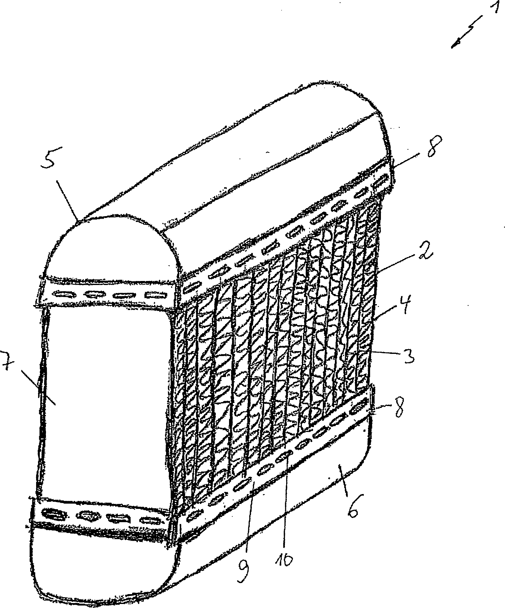
Im Folgenden wird die Erfindung anhand eines Ausführungsbeispiels unter Bezugnahme auf die Zeichnung detailliert erläutert. In der Zeichnung zeigen:in the The invention is based on an embodiment explained in detail with reference to the drawing. In the drawing show:
Zusätzlich
sind an der Außenwand
Weiterhin
sind an der Außenwand
Der
Fertigungsablauf ist dabei wie folgt. Der bereits in einem anderen
Abschnitt (nicht gezeigt) der Produktionsanlage fertig verlötete
Wärmeübertragerblock
Nach
der Prüfung auf Dichtigkeit des Wärmeübertragerblocks
Insgesamt
betrachtet kann bei dem so ausgestalteten Wärmeübertrager
ZITATE ENTHALTEN IN DER BESCHREIBUNGQUOTES INCLUDE IN THE DESCRIPTION
Diese Liste der vom Anmelder aufgeführten Dokumente wurde automatisiert erzeugt und ist ausschließlich zur besseren Information des Lesers aufgenommen. Die Liste ist nicht Bestandteil der deutschen Patent- bzw. Gebrauchsmusteranmeldung. Das DPMA übernimmt keinerlei Haftung für etwaige Fehler oder Auslassungen.This list The documents listed by the applicant have been automated generated and is solely for better information recorded by the reader. The list is not part of the German Patent or utility model application. The DPMA takes over no liability for any errors or omissions.
Zitierte PatentliteraturCited patent literature
- - DE 2703528 A1 [0007] - DE 2703528 A1 [0007]
Claims (10)
Priority Applications (2)
| Application Number | Priority Date | Filing Date | Title |
|---|---|---|---|
| DE202008009811U DE202008009811U1 (en) | 2008-07-21 | 2008-07-21 | Heat exchanger |
| DE102008051841A DE102008051841A1 (en) | 2008-07-21 | 2008-10-17 | Heat exchanger i.e. radiator, for use in motor vehicle, has base element and cooling medium boxes, where element and boxes are connected with one another in fixed and tight manner by glued connection and by locking connection |
Applications Claiming Priority (1)
| Application Number | Priority Date | Filing Date | Title |
|---|---|---|---|
| DE202008009811U DE202008009811U1 (en) | 2008-07-21 | 2008-07-21 | Heat exchanger |
Publications (1)
| Publication Number | Publication Date |
|---|---|
| DE202008009811U1 true DE202008009811U1 (en) | 2009-06-04 |
Family
ID=40719668
Family Applications (2)
| Application Number | Title | Priority Date | Filing Date |
|---|---|---|---|
| DE202008009811U Expired - Lifetime DE202008009811U1 (en) | 2008-07-21 | 2008-07-21 | Heat exchanger |
| DE102008051841A Withdrawn DE102008051841A1 (en) | 2008-07-21 | 2008-10-17 | Heat exchanger i.e. radiator, for use in motor vehicle, has base element and cooling medium boxes, where element and boxes are connected with one another in fixed and tight manner by glued connection and by locking connection |
Family Applications After (1)
| Application Number | Title | Priority Date | Filing Date |
|---|---|---|---|
| DE102008051841A Withdrawn DE102008051841A1 (en) | 2008-07-21 | 2008-10-17 | Heat exchanger i.e. radiator, for use in motor vehicle, has base element and cooling medium boxes, where element and boxes are connected with one another in fixed and tight manner by glued connection and by locking connection |
Country Status (1)
| Country | Link |
|---|---|
| DE (2) | DE202008009811U1 (en) |
Families Citing this family (1)
| Publication number | Priority date | Publication date | Assignee | Title |
|---|---|---|---|---|
| DE102020206409B4 (en) | 2020-05-22 | 2022-03-31 | Hanon Systems | heat exchanger |
Citations (1)
| Publication number | Priority date | Publication date | Assignee | Title |
|---|---|---|---|---|
| DE2703528A1 (en) | 1977-01-28 | 1978-08-03 | Laengerer & Reich Kuehler | Water cooler radiator for engine - has header tank connected by snap fit projections to tube plate |
Family Cites Families (2)
| Publication number | Priority date | Publication date | Assignee | Title |
|---|---|---|---|---|
| EP1450123A1 (en) * | 2003-02-20 | 2004-08-25 | Behr France S.A.R.L. | Mechanically assembled heat exchanger, particularly for motor vehicles |
| DE102004036020A1 (en) * | 2004-07-23 | 2006-02-16 | Behr Gmbh & Co. Kg | Heat exchanger, in particular condenser |
-
2008
- 2008-07-21 DE DE202008009811U patent/DE202008009811U1/en not_active Expired - Lifetime
- 2008-10-17 DE DE102008051841A patent/DE102008051841A1/en not_active Withdrawn
Patent Citations (1)
| Publication number | Priority date | Publication date | Assignee | Title |
|---|---|---|---|---|
| DE2703528A1 (en) | 1977-01-28 | 1978-08-03 | Laengerer & Reich Kuehler | Water cooler radiator for engine - has header tank connected by snap fit projections to tube plate |
Also Published As
| Publication number | Publication date |
|---|---|
| DE102008051841A1 (en) | 2010-01-28 |
Similar Documents
| Publication | Publication Date | Title |
|---|---|---|
| DE69003241T2 (en) | PLATE HEAT EXCHANGER AND METHOD FOR PRODUCING THE SAME. | |
| DE2852408B2 (en) | Clamp connection | |
| DE2036398C3 (en) | cooler | |
| DE3720483A1 (en) | Heat exchanger | |
| DE2852415A1 (en) | TERMINAL CONNECTION | |
| DE3141580A1 (en) | HEAT EXCHANGER WITH MECHANICALLY JOINED TUBES, RIBS AND COLLECTING PLATES | |
| DE102017117093A1 (en) | battery box | |
| DE4243495C5 (en) | Elastomeric seal for heat exchangers | |
| DE102009050884A1 (en) | Exhaust gas heat exchanger | |
| EP0864838A2 (en) | Heat exchanger for automotive vehicle | |
| DE3928453A1 (en) | HEAT EXCHANGER AND A METHOD FOR PRODUCING A GASKET FOR A HEAT EXCHANGER | |
| EP2498040B1 (en) | Heat exchanger and method for manufacturing a heat exchanger | |
| EP2742557A1 (en) | Device for controlling the temperature of an energy accumulator, more particularly for a vehicle, and method for production thereof | |
| DE19527050C2 (en) | Heat exchangers for motor vehicles | |
| DE102016111201A1 (en) | Method for producing a heat exchanger | |
| DE2035947A1 (en) | Device for connecting the pipe plates and water tank of coolers and the like | |
| DE102009009807A1 (en) | Mechanical connector for mechanically connecting tube plate and air box for intercooler of internal combustion engine of motor vehicle, has tube plate's edge region including continuous, linear edge strip above deformable tabs | |
| EP1811259A1 (en) | Fastening assembly for heat exchangers | |
| DE102008051841A1 (en) | Heat exchanger i.e. radiator, for use in motor vehicle, has base element and cooling medium boxes, where element and boxes are connected with one another in fixed and tight manner by glued connection and by locking connection | |
| EP1384968B1 (en) | Heat exchanger and associated process of fabricating | |
| DE102008032287A1 (en) | Adhesive connection for metal flat tube ends, which are part of soldered heat exchanger network, in corresponding openings of collection tank, where each opening has annular space provided around flat tube ends, comprises mounting plate | |
| EP0108958B1 (en) | Connection of metallic heat exchanger tubes to the bottom of a water box | |
| DE4417840A1 (en) | Gasket with throughlet openings for liquids | |
| EP2161526A2 (en) | Method for manufacturing a plate heat exchanger and plate heat exchanger manufactured according to this method | |
| EP2300770B1 (en) | Heat exchanger and method of production |
Legal Events
| Date | Code | Title | Description |
|---|---|---|---|
| R207 | Utility model specification |
Effective date: 20090709 |
|
| R150 | Term of protection extended to 6 years | ||
| R150 | Term of protection extended to 6 years |
Effective date: 20111130 |
|
| R151 | Term of protection extended to 8 years | ||
| R151 | Term of protection extended to 8 years |
Effective date: 20140806 |
|
| R082 | Change of representative |
Representative=s name: GRAUEL, ANDREAS, DIPL.-PHYS. DR. RER. NAT., DE |
|
| R081 | Change of applicant/patentee |
Owner name: MAHLE INTERNATIONAL GMBH, DE Free format text: FORMER OWNER: BEHR GMBH & CO. KG, 70469 STUTTGART, DE Effective date: 20150421 |
|
| R082 | Change of representative |
Representative=s name: GRAUEL, ANDREAS, DIPL.-PHYS. DR. RER. NAT., DE Effective date: 20150421 |
|
| R152 | Term of protection extended to 10 years | ||
| R071 | Expiry of right |