DE19755897B4 - Device for synchronizing a message receiver - Google Patents
Device for synchronizing a message receiver Download PDFInfo
- Publication number
- DE19755897B4 DE19755897B4 DE19755897A DE19755897A DE19755897B4 DE 19755897 B4 DE19755897 B4 DE 19755897B4 DE 19755897 A DE19755897 A DE 19755897A DE 19755897 A DE19755897 A DE 19755897A DE 19755897 B4 DE19755897 B4 DE 19755897B4
- Authority
- DE
- Germany
- Prior art keywords
- signal
- output
- envelope
- noise
- detector
- Prior art date
- Legal status (The legal status is an assumption and is not a legal conclusion. Google has not performed a legal analysis and makes no representation as to the accuracy of the status listed.)
- Expired - Fee Related
Links
- 238000000034 method Methods 0.000 claims description 18
- 230000005540 biological transmission Effects 0.000 claims description 14
- 238000001914 filtration Methods 0.000 claims description 5
- 238000001514 detection method Methods 0.000 description 17
- 238000012937 correction Methods 0.000 description 15
- 238000012935 Averaging Methods 0.000 description 11
- 238000010586 diagram Methods 0.000 description 11
- 238000012545 processing Methods 0.000 description 6
- 238000004891 communication Methods 0.000 description 5
- 238000004364 calculation method Methods 0.000 description 4
- 230000001360 synchronised effect Effects 0.000 description 4
- 230000000875 corresponding effect Effects 0.000 description 3
- 230000000694 effects Effects 0.000 description 3
- 230000003321 amplification Effects 0.000 description 2
- 230000015556 catabolic process Effects 0.000 description 2
- 230000002596 correlated effect Effects 0.000 description 2
- 238000006731 degradation reaction Methods 0.000 description 2
- 238000005562 fading Methods 0.000 description 2
- 238000003199 nucleic acid amplification method Methods 0.000 description 2
- 230000018199 S phase Effects 0.000 description 1
- 230000002411 adverse Effects 0.000 description 1
- 238000004458 analytical method Methods 0.000 description 1
- 238000006243 chemical reaction Methods 0.000 description 1
- 230000001427 coherent effect Effects 0.000 description 1
- 238000007796 conventional method Methods 0.000 description 1
- 230000001419 dependent effect Effects 0.000 description 1
- 230000006866 deterioration Effects 0.000 description 1
- 238000011161 development Methods 0.000 description 1
- 230000018109 developmental process Effects 0.000 description 1
- 238000012423 maintenance Methods 0.000 description 1
- 230000002441 reversible effect Effects 0.000 description 1
- 238000005070 sampling Methods 0.000 description 1
Images


Classifications
-
- H—ELECTRICITY
- H03—ELECTRONIC CIRCUITRY
- H03L—AUTOMATIC CONTROL, STARTING, SYNCHRONISATION OR STABILISATION OF GENERATORS OF ELECTRONIC OSCILLATIONS OR PULSES
- H03L7/00—Automatic control of frequency or phase; Synchronisation
- H03L7/06—Automatic control of frequency or phase; Synchronisation using a reference signal applied to a frequency- or phase-locked loop
- H03L7/08—Details of the phase-locked loop
- H03L7/085—Details of the phase-locked loop concerning mainly the frequency- or phase-detection arrangement including the filtering or amplification of its output signal
- H03L7/095—Details of the phase-locked loop concerning mainly the frequency- or phase-detection arrangement including the filtering or amplification of its output signal using a lock detector
-
- H—ELECTRICITY
- H03—ELECTRONIC CIRCUITRY
- H03G—CONTROL OF AMPLIFICATION
- H03G3/00—Gain control in amplifiers or frequency changers
- H03G3/20—Automatic control
- H03G3/30—Automatic control in amplifiers having semiconductor devices
- H03G3/3052—Automatic control in amplifiers having semiconductor devices in bandpass amplifiers (H.F. or I.F.) or in frequency-changers used in a (super)heterodyne receiver
-
- H—ELECTRICITY
- H04—ELECTRIC COMMUNICATION TECHNIQUE
- H04B—TRANSMISSION
- H04B1/00—Details of transmission systems, not covered by a single one of groups H04B3/00 - H04B13/00; Details of transmission systems not characterised by the medium used for transmission
- H04B1/06—Receivers
- H04B1/10—Means associated with receiver for limiting or suppressing noise or interference
- H04B1/1027—Means associated with receiver for limiting or suppressing noise or interference assessing signal quality or detecting noise/interference for the received signal
Landscapes
- Engineering & Computer Science (AREA)
- Computer Networks & Wireless Communication (AREA)
- Signal Processing (AREA)
- Circuits Of Receivers In General (AREA)
- Control Of Amplification And Gain Control (AREA)
- Digital Transmission Methods That Use Modulated Carrier Waves (AREA)
- Noise Elimination (AREA)
- Monitoring And Testing Of Transmission In General (AREA)
- Input Circuits Of Receivers And Coupling Of Receivers And Audio Equipment (AREA)
- Measuring Pulse, Heart Rate, Blood Pressure Or Blood Flow (AREA)
Abstract
Rauschabschätzungseinrichtung zum Bestimmen der Rauschleistung eines Empfängereingangssignals, wobei das Empfängereingangssignal eine Rauschkomponente und eine Signalkomponente enthält, mit: einem quadratischen Leistungsdetektor (50), der auf das Empfängereingangssignal anspricht und eine Ausgabe hat; einem Quadratwurzel-Detektor (52), der geschaltet ist, um die Ausgabe von dem quadratischen Leistungsdetektor (50) zu empfangen, und der eine Ausgabe hat, die eine momentane Hüllkurve des Eingangssignals darstellt; einer Einrichtung (54) zum Erzeugen eines zeitgemittelten statistischen Hüllkurvensignals, das den statistischen Mittelwert der momentanen Hüllkurve des Eingangssignals darstellt; einer Einrichtung (56) zum Erzeugen eines Differenzsignals, das die Differenz zwischen der momentanen Hüllkurve des Eingangssignals und dem zeitgemittelten statistischen Hüllkurvensignal darstellt; und einer Einrichtung (58, 60) zum Umwandeln des Differenzsignals in eine zeitgemittelte Abschätzung der Eingangsrauschleistung.Noise estimator for determining the noise power of a receiver input signal, the receiver input signal including a noise component and a signal component, comprising: a quadratic power detector (50) responsive to the receiver input signal and having an output; a square root detector (52) connected to receive the output from the quadratic power detector (50) and having an output representative of an instantaneous envelope of the input signal; means (54) for generating a time-averaged statistical envelope signal representing the statistical average of the instantaneous envelope of the input signal; means (56) for generating a difference signal representing the difference between the instantaneous envelope of the input signal and the time-averaged statistical envelope signal; and means (58, 60) for converting the difference signal into a time-averaged estimate of the input noise power.
Description
Die vorliegende Erfindung betrifft einen Nachrichtenempfänger und insbesondere eine Vorrichtung zur Synchronisierung eines digitalen Nachrichtenempfängers mit einem Nachrichtensender vor der Übertragung von Nachrichten bzw. Daten.The present invention relates to a message receiver, and more particularly to a device for synchronizing a digital message receiver with a message transmitter prior to transmission of messages or data.
Ein Nachrichtenübertragungssystem umfaßt mindestens einen Sender (Nachrichtensender) und einen Empfänger (Nachrichtenempfänger). Der Sender und der Empfänger sind über einen Übertragungskanal miteinander verbunden, um zwischen dem Sender und dem Empfänger Informations- bzw. Nachrichtensignale übertragen zu können. Ein digitaler Empfänger in einem Nachrichtenübertragungssystem hat normalerweise einen Verstärker mit einem Verstärkungsgrad, der mit Hilfe eines Steuersignals eingestellt wird. Das Verfahren zum Einstellen des Verstärkungsgrades mit Hilfe dieses Steuersignals basiert auf dem vom Sender empfangenen Informationssignal. Dieses Einstell-Verfahren ist auch als automatische Verstärkungssteuerung (Automatic Gain Control = AGC) bekannt.A communication system comprises at least one transmitter (message transmitter) and one receiver (message receiver). The transmitter and the receiver are connected to each other via a transmission channel in order to be able to transmit information or message signals between the transmitter and the receiver. A digital receiver in a communication system normally has an amplifier with a gain set by means of a control signal. The method of adjusting the gain using this control signal is based on the information signal received from the transmitter. This adjustment method is also known as Automatic Gain Control (AGC).
Bevor Daten von dem Sender zum Empfänger übertragen werden können, muß der Empfänger mit dem Sender synchronisiert werden. Vor der Synchronisierung des Empfängers mit den Frequenz-, Phasen- und Zeitvariablen des empfangenen Signals muß jedoch in dem Empfänger zunächst die Amplitudenhöhe des empfangenen Signals bestimmt werden. Mittels eines AGC-Steuerschaltkreises bzw. eines entsprechenden Algorithmus wird automatisch der Verstärkungsgrad des Verstärkers eingestellt, um eine optimale Signalerfassung und Signalverarbeitung zu erreichen. Wenn der Verstärkungsgrad des Verstärkers zu klein ist, kann das interne Empfängerrauschen dominieren, und infolge dessen tritt eine Verschlechterung der Signalerfassung ein. Wenn jedoch der Verstärkungsgrad zu groß ist, erreichen die analogen Schaltkreis-Komponenten des Verstärkers schnell ihre Sättigung, was zu Nicht-Linearitäten und damit zu einer Verschlechterung der Signalverarbeitung des Empfängers führt. Nur bei einer korrekten Einstellung des Verstärkungsgrades des Verstärkers arbeitet der Empfänger optimal, um die anderen Synchronisierungsvariablen abschätzen zu können, das heißt, die Frequenz-, Phasen- und Zeitvariablen. Eine Synchronisierung dieser Variablen ist aber erforderlich, bevor der Empfänger mit der Demodulation von Daten bzw. mit anderen Signalverarbeitungsfunktionen beginnen kann.Before data can be transmitted from the sender to the receiver, the receiver must be synchronized with the sender. However, prior to the synchronization of the receiver with the frequency, phase and time variables of the received signal, the amplitude level of the received signal must first be determined in the receiver. By means of an AGC control circuit or a corresponding algorithm, the gain of the amplifier is automatically adjusted in order to achieve optimum signal detection and signal processing. If the gain of the amplifier is too small, the internal receiver noise may dominate, and as a result, a deterioration of the signal detection occurs. However, if the gain is too high, the analog circuit components of the amplifier quickly saturate, resulting in non-linearities and, thus, degradation in the signal processing of the receiver. Only with a correct gain adjustment of the amplifier does the receiver work optimally to estimate the other synchronization variables, that is, the frequency, phase and time variables. However, synchronization of these variables is required before the receiver can begin demodulating data or other signal processing functions.
Bei einem bekannten Nachrichtenübertragungssystem wird die Quadraturmodulation verwendet. Ein Pilotträgersignal wird übertragen, um das Empfangen und das Dekodieren von übertragenen Informationssignalen zu erleichtern. Das Pilotträgersignal wird sowohl zur Amplitudenkorrektur als auch zur Phasenkorrektur verwendet. Bei Verwendung dieses Pilotträgersignals führt jedoch Selektivschwund (Selective Fading) auf dem Übertragungskanal häufig zu Problemen. Wenn digitale Informationen synchron empfangen werden sollen, so wird die Aufrechterhaltung der Synchronisierung häufig auch durch Kanal-Schwund (Channel Fading) und durch Rauschen verhindert.In a known communication system, quadrature modulation is used. A pilot carrier signal is transmitted to facilitate receiving and decoding transmitted information signals. The pilot carrier signal is used for both amplitude correction and phase correction. When using this pilot carrier signal, however, selective fading on the transmission channel often causes problems. When digital information is to be received synchronously, the maintenance of synchronization is often prevented by channel fading and noise.
Die
Die
Die
Es ist daher eine Aufgabe der vorliegenden Erfindung, einen Empfänger für ein Nachrichtenübertragungssystem zu schaffen, der mit einer bestimmten Erfassungswahrscheinlichkeit arbeitet, und zwar unabhängig von der Berechnung des Verstärkungsgrades durch den AGC-Schaltkreis des Empfängers, die auf dem Pegel der Signalleistung einschließlich der Rauschleistung basiert.It is therefore an object of the present invention to provide a receiver for a communication system which operates with a certain probability of detection irrespective of the calculation of the gain by the AGC circuit of the receiver based on the level of the signal power including the noise power ,
Diese Aufgabe wird durch einen Empfänger mit einer Rauschabschätzungseinrichtung mit den Merkmalen des Anspruchs 1 bzw. mit einem Synchronisationsdetektor mit den Merkmalen des Anspruchs 6 gelöst. In den jeweiligen abhängigen Ansprüchen sind vorteilhafte und bevorzugte Weiterbildungen der erfindungsgemäßen Einrichtungen angegeben.This object is achieved by a receiver with a noise estimation device having the features of claim 1 or with a synchronization detector having the features of claim 6. In the respective dependent claims advantageous and preferred developments of the inventive devices are given.
Die vorliegende Erfindung betrifft allgemein die Synchronisierung eines Empfängers mit einem Sender und insbesondere die Korrektur des Schwellenwertes, der für den Phasenverriegelungsstatus (Phaselock Status) in einem digitalen Empfänger verwendet wird. Der Empfänger arbeitet mit einer bestimmten minimalen Signalerfassungswahrscheinlichkeit, und zwar unabhängig von der Berechnung der Leistung des Signal-Rausch-Abstandes durch den AGC-Schaltkreis.The present invention relates generally to the synchronization of a receiver with a transmitter, and more particularly to the correction of the threshold used for the phase lock status in a digital receiver. The receiver operates with a certain minimum signal detection probability, regardless of the calculation of the power of the signal-to-noise ratio by the AGC circuit.
Gemäß der vorliegenden Erfindung ist eine Rauschabschätzungseinrichtung zur Schwellenwertkorrektur der Phasenverriegelung (Phaselock) in einem Empfänger vorgesehen, bei der ein Rauschabschätzungsschaltkreis eine Schwellenwertkorrektur für die Phasenverriegelung als eine Funktion der Eingangsrauschleistung bewirkt, um eine Vorspannung zu vermindern, die durch den AGC-Schaltkreis am Ausgang eines Quadraturphasendetektors erzeugt wird. Die erfindungsgemäße Rauschleistungsabschätzungseinrichtung verwendet die ergodischen Eigenschaften des Eingangssignals und eine Zeitmittelung, um einen statistischen Mittelwert einer Eingangssignalhüllkurve zu erzeugen. Dieses Zeitmittel des Eingangssignals wird vom Momentanwert der erfaßten Hüllkurve subtrahiert, und der berechnete momentane Fehler, der aus dieser Subtraktion resultiert, wird quadriert und zeitgemittelt, woraus eine Abschätzung der Eingangsrauschleistung resultiert.In accordance with the present invention, there is provided noise estimation means for phase lock threshold correction (phaselock) in a receiver, wherein a noise estimation circuit effects a phase lock threshold correction as a function of input noise power to reduce a bias developed by the AGC circuit at the output of a Quadrature phase detector is generated. The noise power estimator of the invention uses the ergodic characteristics of the input signal and time averaging to produce a statistical average of an input signal envelope. This time average of the input signal is subtracted from the instantaneous value of the detected envelope, and the calculated instantaneous error resulting from this subtraction is squared and time averaged, resulting in an estimate of the input noise power.
Gemäß der vorliegenden Erfindung ist eine Rauschabschätzungseinrichtung zur Berechnung der Rauschabschätzung eines Eingangssignals vorgesehen, wobei das Eingangssignal eine Signalkomponente und eine Rauschkomponente enthält. Der Abschätzungsschaltkreis hat ein Filter, um aus dem Eingangssignal das Breitbandrauschen herauszufiltern. Außerdem hat die Rauschabschätzungseinrichtung der vorliegenden Erfindung einen quadratischen Leistungsdetektor, der auf die Ausgabe von einem Tiefpaßfilter anspricht, und einen Hüllkurvendetektor, der mit dem Ausgang des quadratischen Leistungsdetektors gekoppelt ist. Eine zeitgemittelte Hüllkurve des Eingangssignals wird von einem Tiefpaßfilter ausgegeben, wodurch die Zeitmittelung durchgeführt wird, und diese Ausgabe wird einem Subtrahierglied zugeführt, das außerdem den Momentanwert der eingehenden Hüllkurve empfängt, um ein momentanes Fehlersignal zu erzeugen. Dieses momentane Fehlersignal wird quadriert und einem Tiefpaßfilter zugeführt, wodurch ebenfalls eine Zeitmittelung bewirkt wird. Das aus dieser Zeitmittelung resultierende Signal ist eine Rauschabschätzung des Eingangssignals. Diese Rauschabschätzung wird dann für die Schwellenwertkorrektur verwendet, um eine Phasenverriegelung (Phaselock) zwischen einem Empfänger und einem Sender zu bewirken.According to the present invention, there is provided a noise estimation means for calculating the noise estimate of an input signal, the input signal including a signal component and a noise component. The estimation circuit has a filter to filter out the wideband noise from the input signal. In addition, the noise estimator of the present invention has a quadratic power detector responsive to the output of a low pass filter and an envelope detector coupled to the output of the quadratic power detector. A time-averaged envelope of the input signal is output from a low-pass filter, thereby performing time averaging, and this output is applied to a subtracter, which also receives the instantaneous value of the incoming envelope to produce a current error signal. This instantaneous error signal is squared and fed to a low-pass filter, which also causes a time averaging. The signal resulting from this time averaging is a noise estimate of the input signal. This noise estimate is then used for the threshold correction to effect a phase lock (phase lock) between a receiver and a transmitter.
Die Erfindung wird nun anhand eines Ausführungsbeispiels unter Bezugnahme auf die Zeichnungen beschrieben. Es zeigen:The invention will now be described by way of example with reference to the drawings. Show it:
Zunächst wird auf
Die gesendete Nachricht s(t) ist durch die nachfolgende Gleichung definiert:
- A(t)
- die gesendete Amplitude,
- f
- die Trägerfrequenz,
- t
- die Senderzeitreferenz,
- Φm(t)
- die Datennachricht, und
- θ
- die Senderphasenreferenz ist.
- At)
- the transmitted amplitude,
- f
- the carrier frequency,
- t
- the sender time reference,
- Φ m (t)
- the data message, and
- θ
- the sender phase reference is.
Der Empfänger
- S(t)
- die empfangene Amplitude,
- f
- die Trägerfrequenz,
- t
- die Senderzeitreferenz,
- T
- die Verzögerung, die durch den Übertragungskanal und den Empfänger hervorgerufen wird,
- Φm(t)
- die Datennachricht,
- θr
- die Empfängerphasenreferenz, und
- n(t)
- das Kanal- und Empfängerrauschen ist.
- S (t)
- the received amplitude,
- f
- the carrier frequency,
- t
- the sender time reference,
- T
- the delay caused by the transmission channel and the receiver
- Φ m (t)
- the data message,
- θ r
- the receiver phase reference, and
- n (t)
- the channel and receiver noise is.
Bevor vom Sender
Zur optimalen Signalerfassung und Signalverarbeitung muß mit Hilfe eines Schaltkreises zur automatischen Verstärkungssteuerung (AGC-Schaltkreis) bzw. eines entsprechenden Algorithmus der Verstärkungsgrad des Verstärkers des Empfängers
Nach dem Einstellen der Verstärkungsgrade der Verstärker des Empfängers
In
Außerdem wird dem Mischer
Die Ausgabe des VCO
Im Anschluß wird der Betrieb des Schaltkreises aus
Die bevorzugte Technik zur Erfassung eines Phasenverriegelungsstatus ist die Verwendung eines Quadraturphasendetektors
In
In 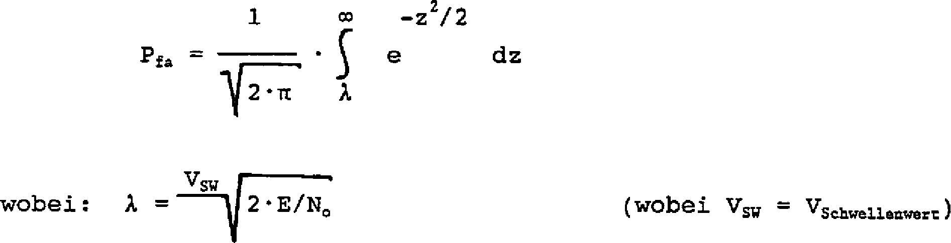
Durch Einsetzen des Wertes der Wahrscheinlichkeit eines Fehlalarms (fehlerhafte Erfassung) aus
- G
- der Verstärkungsgrad der Verstärker
18 , - θc
- der Synchronisierungsphasenfehler, und
- S(t)
- die Amplitude des empfangenen Signals r(t) ist.
- G
- the gain of the
amplifiers 18 . - θ c
- the synchronization phase error, and
- S (t)
- the amplitude of the received signal r (t) is.
Diese Gleichung zeigt, daß der Phasenverriegelungsstatus des Empfängers
Beim Betrieb des Empfängers aus
In
Nachfolgend wird auf
Gemäß der vorliegenden Erfindung funktioniert ein Quadraturdetektor
Unter Bezugnahme auf
In
BezugszeichenlisteLIST OF REFERENCE NUMBERS
- 1010
- Sendertransmitter
- 1212
- Empfängerreceiver
- 1414
- Übertragungskanaltransmission channel
- 1616
- Eingangsfilterinput filter
- 1818
- Empfänger-VerstärkerReceiver amplifier
- 2020
- Mischermixer
- 2222
- Mischermixer
- 2424
- Leistungsdetektorpower detector
- 2525
- AGC-SchleifenfilterAGC loop filter
- 2626
- spannungsgesteuerter Oszillator (VCO)Voltage Controlled Oscillator (VCO)
- 2828
- Schleifenfilterloop filter
- 3030
- TrägerschleifenfilterCarrier loop filter
- 3232
- 90°-Phasenschieber90 ° phase shifter
- 3434
- QuadraturphasendetektorQuadrature phase detector
- 3636
- Tiefpaßfilterlow pass filter
- 3838
- SchwellenwertvergleicherThreshold comparator
- 4040
- Phasenregelkreis-QuadraturdetektorPhase-locked loop quadrature detector
- 4646
- Mischermixer
- 4848
- Tiefpaßfilterlow pass filter
- 5050
- quadratischer Leistungsdetektorsquare power detector
- 5252
- Hüllkurvendetektorenvelope
- 5454
- Tiefpaßfilterlow pass filter
- 5656
- Addiereinrichtungadder
- 5858
- quadratischer Leistungsdetektorsquare power detector
- 6060
- Tiefpaßfilterlow pass filter
- 6262
- Verstärkeramplifier
- 6464
- SignalabschätzungseinrichtungSignal estimator
- 6666
- Addiereinrichtungadder
- 6868
- Referenzreference
- 7070
- Schleifenfilterloop filter
- 7272
- Hüllkurvendetektorenvelope
- 7474
- Tiefpaßfilterlow pass filter
- 7676
- Hochpaßfilterhighpass filter
- 7878
- quadratischer Leistungsdetektorsquare power detector
- 8080
- Addiereinrichtungadder
- 8282
- quadratischer Leistungsdetektorsquare power detector
- 8484
- Tiefpaßfilterlow pass filter
- 8686
- Hüllkurvendetektorenvelope
Claims (25)
Applications Claiming Priority (2)
| Application Number | Priority Date | Filing Date | Title |
|---|---|---|---|
| US762593 | 1985-08-02 | ||
| US08/762,593 US5901173A (en) | 1996-12-09 | 1996-12-09 | Noise Estimator |
Publications (2)
| Publication Number | Publication Date |
|---|---|
| DE19755897A1 DE19755897A1 (en) | 1998-06-10 |
| DE19755897B4 true DE19755897B4 (en) | 2012-06-28 |
Family
ID=25065516
Family Applications (1)
| Application Number | Title | Priority Date | Filing Date |
|---|---|---|---|
| DE19755897A Expired - Fee Related DE19755897B4 (en) | 1996-12-09 | 1997-12-08 | Device for synchronizing a message receiver |
Country Status (6)
| Country | Link |
|---|---|
| US (3) | US5901173A (en) |
| AU (1) | AU739342B2 (en) |
| CA (1) | CA2218806C (en) |
| DE (1) | DE19755897B4 (en) |
| GB (1) | GB2320168B (en) |
| IT (1) | IT1297100B1 (en) |
Families Citing this family (17)
| Publication number | Priority date | Publication date | Assignee | Title |
|---|---|---|---|---|
| SE506200C2 (en) * | 1996-03-25 | 1997-11-17 | Ericsson Telefon Ab L M | Device and method for offsetting voltage compensation when receiving optical signals |
| JPH09321736A (en) * | 1996-05-27 | 1997-12-12 | Sony Corp | Receiving method and receiver |
| US6229856B1 (en) * | 1997-04-14 | 2001-05-08 | Masimo Corporation | Method and apparatus for demodulating signals in a pulse oximetry system |
| EP1082050B1 (en) * | 1998-06-03 | 2011-08-24 | Masimo Corporation | Stereo pulse oximeter |
| US8014724B2 (en) | 1999-10-21 | 2011-09-06 | Broadcom Corporation | System and method for signal limiting |
| US6801092B1 (en) * | 2003-04-08 | 2004-10-05 | Broadcom Corp. | Phase locked loop that avoids false locking |
| KR100334911B1 (en) * | 2000-01-28 | 2002-05-04 | 오길록 | Prediction Method of Received Signal Level in Adaptive Transmission Systems |
| KR20100058636A (en) * | 2000-03-28 | 2010-06-03 | 인터디지탈 테크날러지 코포레이션 | Cdma system which uses pre-rotation before transmission |
| DE10050330A1 (en) * | 2000-10-11 | 2002-04-25 | Infineon Technologies Ag | Signal strength compensation device for mobile radio receiver uses mean value of signal strength for previously received data symbols |
| US7076001B2 (en) * | 2001-10-16 | 2006-07-11 | Harris Corporation | System and method for an in-service decision-directed signal to noise ratio estimator |
| DE60331728D1 (en) * | 2003-07-15 | 2010-04-29 | St Microelectronics Sa | Automatic gain control method, for example in a telecommunication system, apparatus and computer program therefor |
| US6867728B1 (en) * | 2003-11-06 | 2005-03-15 | Lockheed Martin Corporation | Methods and systems for identifying signals-of-interest |
| EP1557680A1 (en) * | 2004-01-26 | 2005-07-27 | STMicroelectronics S.r.l. | Device for detecting the power of a radio frequency signal |
| CN100525123C (en) * | 2006-08-10 | 2009-08-05 | 华为技术有限公司 | Receiver and wireless signal receiving method |
| US8549191B2 (en) * | 2010-01-04 | 2013-10-01 | Csr Technology Inc. | Method and apparatus for SATA hot unplug |
| FR3105661B1 (en) * | 2019-12-20 | 2021-11-26 | Commissariat Energie Atomique | Envelope detection circuit and receiver incorporating this circuit |
| US20230208456A1 (en) * | 2021-12-27 | 2023-06-29 | Hughes Network Systems, Llc | Communication terminal configured to adjust for interference and methods of use |
Citations (3)
| Publication number | Priority date | Publication date | Assignee | Title |
|---|---|---|---|---|
| US4048566A (en) * | 1976-01-05 | 1977-09-13 | Motorola Inc. | Suppressed carrier automatic gain control circuitry |
| US4811423A (en) * | 1986-12-23 | 1989-03-07 | Motorola, Inc. | SSB receiver with improved feedforward AGC |
| US4835790A (en) * | 1987-06-23 | 1989-05-30 | Nec Corporation | Carrier-to-noise detector for digital transmission systems |
Family Cites Families (32)
| Publication number | Priority date | Publication date | Assignee | Title |
|---|---|---|---|---|
| SU640429A1 (en) * | 1969-08-27 | 1978-12-30 | Институт Горного Дела Со Ан Ссср | Arrangement for measuring signal-to-noise ratio in discrete communication channels |
| US3879664A (en) * | 1973-05-07 | 1975-04-22 | Signatron | High speed digital communication receiver |
| US4101839A (en) * | 1974-11-27 | 1978-07-18 | The United States Of America As Represented By The Secretary Of The Navy | Analog-digital ratio detector |
| US4360929A (en) * | 1979-06-22 | 1982-11-23 | Matsushita Electric Industrial Co., Ltd. | Automatic gain control circuit |
| JPS5868330A (en) * | 1981-10-19 | 1983-04-23 | Nippon Telegr & Teleph Corp <Ntt> | Detecting circuit for identical frequency interference |
| US5220468A (en) * | 1982-05-10 | 1993-06-15 | Digital Equipment Corporation | Disk drive with constant bandwidth automatic gain control |
| NL8303563A (en) * | 1983-10-17 | 1985-05-17 | Philips Nv | DEVICE FOR DISPLAYING DIGITAL INFORMATION THROUGH A TRANSMISSION MEDIA. |
| GB2174576B (en) * | 1985-04-29 | 1989-06-28 | Plessey Co Plc | Improvements in or relating to receivers |
| US4637066A (en) * | 1985-07-02 | 1987-01-13 | General Motors Corporation | Noise blanking signal generator for AM radio |
| EP0305603B1 (en) * | 1987-09-03 | 1993-03-10 | Koninklijke Philips Electronics N.V. | Gain and phase correction in a dual branch receiver |
| US4870660A (en) * | 1987-12-28 | 1989-09-26 | Unisys Corporation | Variable frequency rate receiver |
| US4888787A (en) * | 1988-09-26 | 1989-12-19 | David Kisak | Receiver apparatus for spread spectrum communication systems |
| US4901332A (en) * | 1988-10-27 | 1990-02-13 | Unisys Corp. | Noncoherent-coherent A.C. coupled base band AGC receiver |
| US4910467A (en) * | 1988-11-02 | 1990-03-20 | Motorola, Inc. | Method and apparatus for decoding a quadrature modulated signal |
| US5301364A (en) * | 1988-11-30 | 1994-04-05 | Motorola, Inc. | Method and apparatus for digital automatic gain control in a receiver |
| US5134723A (en) * | 1990-04-20 | 1992-07-28 | Carson William E | Radio sensitivity enhancer |
| US5083304A (en) * | 1990-09-28 | 1992-01-21 | Motorola, Inc. | Automatic gain control apparatus and method |
| US5150384A (en) * | 1990-09-28 | 1992-09-22 | Motorola, Inc. | Carrier recovery method and apparatus having an adjustable response time determined by carrier signal parameters |
| US5261004A (en) * | 1991-12-17 | 1993-11-09 | Delco Electronics Corporation | Noise blanking circuit for AM stero |
| US5291525A (en) * | 1992-04-06 | 1994-03-01 | Motorola, Inc. | Symmetrically balanced phase and amplitude base band processor for a quadrature receiver |
| JP2762836B2 (en) * | 1992-04-09 | 1998-06-04 | 日本電気株式会社 | Interference wave canceller |
| DE69332021T2 (en) * | 1992-06-08 | 2003-01-16 | Motorola Inc | AUTOMATIC GAIN REGULATION FOR A RECEIVER |
| US5375145A (en) * | 1992-08-27 | 1994-12-20 | Quantum Corporation | Multi-mode gain control loop for PRML class IV sampling data detection channel |
| EP0588206A1 (en) * | 1992-09-15 | 1994-03-23 | Robert Bosch Gmbh | Method and apparatus for producing a control signal |
| FR2706711B1 (en) * | 1993-06-17 | 1996-10-18 | Matra Communication | Method and device for demodulating digital signal. |
| US5353301A (en) * | 1993-09-17 | 1994-10-04 | Motorola, Inc. | Method and apparatus for combining multipath spread-spectrum signals |
| GB9320068D0 (en) * | 1993-09-29 | 1993-11-17 | Sgs Thomson Microelectronics | Demodulation of fm audio carrier |
| US5585975A (en) * | 1994-11-17 | 1996-12-17 | Cirrus Logic, Inc. | Equalization for sample value estimation and sequence detection in a sampled amplitude read channel |
| US5796535A (en) * | 1995-05-12 | 1998-08-18 | Cirrus Logic, Inc. | Sampled amplitude read channel employing a user data frequency synthesizer and a servo data frequency synthesizer |
| US5563916A (en) * | 1995-06-05 | 1996-10-08 | Hitachi America, Ltd. | Apparatus and method for varying the slew rate of a digital automatic gain control circuit |
| US5892631A (en) * | 1995-09-08 | 1999-04-06 | Seagate Technology, Inc. | Method and an arrangement for detecting state transitions in a read signal during a bit cell timing window |
| US5802118A (en) * | 1996-07-29 | 1998-09-01 | Cirrus Logic, Inc. | Sub-sampled discrete time read channel for computer storage systems |
-
1996
- 1996-12-09 US US08/762,593 patent/US5901173A/en not_active Expired - Lifetime
-
1997
- 1997-10-21 CA CA002218806A patent/CA2218806C/en not_active Expired - Lifetime
- 1997-10-23 GB GB9722431A patent/GB2320168B/en not_active Expired - Fee Related
- 1997-12-01 AU AU46799/97A patent/AU739342B2/en not_active Ceased
- 1997-12-05 IT IT97RM000754A patent/IT1297100B1/en active IP Right Grant
- 1997-12-08 DE DE19755897A patent/DE19755897B4/en not_active Expired - Fee Related
-
1998
- 1998-06-30 US US09/109,307 patent/US6094463A/en not_active Expired - Lifetime
- 1998-06-30 US US09/109,308 patent/US6229858B1/en not_active Expired - Lifetime
Patent Citations (3)
| Publication number | Priority date | Publication date | Assignee | Title |
|---|---|---|---|---|
| US4048566A (en) * | 1976-01-05 | 1977-09-13 | Motorola Inc. | Suppressed carrier automatic gain control circuitry |
| US4811423A (en) * | 1986-12-23 | 1989-03-07 | Motorola, Inc. | SSB receiver with improved feedforward AGC |
| US4835790A (en) * | 1987-06-23 | 1989-05-30 | Nec Corporation | Carrier-to-noise detector for digital transmission systems |
Also Published As
| Publication number | Publication date |
|---|---|
| CA2218806C (en) | 2004-02-17 |
| GB2320168A (en) | 1998-06-10 |
| AU739342B2 (en) | 2001-10-11 |
| US6094463A (en) | 2000-07-25 |
| US5901173A (en) | 1999-05-04 |
| AU4679997A (en) | 1998-06-11 |
| DE19755897A1 (en) | 1998-06-10 |
| CA2218806A1 (en) | 1998-06-09 |
| GB2320168B (en) | 2001-08-08 |
| IT1297100B1 (en) | 1999-08-03 |
| GB9722431D0 (en) | 1997-12-24 |
| US6229858B1 (en) | 2001-05-08 |
| ITRM970754A1 (en) | 1999-06-05 |
Similar Documents
| Publication | Publication Date | Title |
|---|---|---|
| DE19755897B4 (en) | Device for synchronizing a message receiver | |
| DE69030892T2 (en) | Frequency control device and method for a digital radio receiver | |
| DE2309167C2 (en) | Method and circuit arrangement for correcting an electrical transmission signal corrupted by phase tremors | |
| DE19680412B4 (en) | Symbol time recovery circuit and associated method | |
| EP0486554B1 (en) | Process and device for converting digitally modulated high-frequency reception signals | |
| DE3685645T2 (en) | SYSTEM FOR COMPENSATING A RADIO INTERFERENCE SIGNAL. | |
| DE60216400T2 (en) | Method and apparatus for noise pulse detection, demodulator operation method, demodulator and radio receiver | |
| DE60005855T2 (en) | RADIO RECEIVER WITH COMPLEX FILTERS AND COMPLEX GAIN CONTROL FOR LOW OR ZERO HERTZ INTERMEDIATE FREQUENCY | |
| DE60133412T2 (en) | VARIABLE SWITCH-DISCONNECTOR AND METHOD FOR CORRECTING DC TRANSMISSIONS IN A RECEIVER | |
| DE69833251T2 (en) | CARRIER RECOVERY IN RECEIVERS FOR DIGITAL TONE RADIO SIGNALS | |
| DD292788A5 (en) | METHOD AND DEVICE FOR AUTOMATIC FREQUENCY CONTROL | |
| DE68928362T2 (en) | Digital automatic frequency control with pure sine waves | |
| DE2921089C3 (en) | Method for generating a pseudo error signal in an error rate monitoring unit and circuit for carrying out the method | |
| DE3789984T2 (en) | Noise signal detection by sampling the digital fundamental frequency signal at an eye opening. | |
| DE10025566A1 (en) | Method and device for clock control of a digital receiver | |
| DE69726377T2 (en) | Frequency setting method and circuit for digital receivers | |
| DE102014104524B4 (en) | Receiver capable of detecting frequency deviations and methods therefor | |
| DE10393730T5 (en) | Apparatus and method for determining an NTSC co-channel interference | |
| DE69023396T2 (en) | Arrangement for quality assessment of a transmission link. | |
| DE112009002217T5 (en) | Automatic gain control and DC offset compensation | |
| DE69927957T2 (en) | Demodulator with rotation means for frequency offset correction | |
| DE4292274C2 (en) | Automatic frequency control through an adaptive filter | |
| DE4300126C2 (en) | Timing reproducer | |
| DE10157392C2 (en) | Receiver with offset compensation | |
| EP1020058B1 (en) | Pilot signal search method |
Legal Events
| Date | Code | Title | Description |
|---|---|---|---|
| 8181 | Inventor (new situation) |
Free format text: STEPHENS, DONALD R., CLEARWATER, FLA., US MOSLEY, WILLIAM JR., SEMINOLE, FLA., US |
|
| 8127 | New person/name/address of the applicant |
Owner name: RAYTHEON CO. (N.D.GES.D. STAATES DELAWARE), LEXING |
|
| 8110 | Request for examination paragraph 44 | ||
| R018 | Grant decision by examination section/examining division | ||
| R020 | Patent grant now final |
Effective date: 20120929 |
|
| R119 | Application deemed withdrawn, or ip right lapsed, due to non-payment of renewal fee |
Effective date: 20130702 |