EP0486554B1 - Process and device for converting digitally modulated high-frequency reception signals - Google Patents
Process and device for converting digitally modulated high-frequency reception signals Download PDFInfo
- Publication number
- EP0486554B1 EP0486554B1 EP90912008A EP90912008A EP0486554B1 EP 0486554 B1 EP0486554 B1 EP 0486554B1 EP 90912008 A EP90912008 A EP 90912008A EP 90912008 A EP90912008 A EP 90912008A EP 0486554 B1 EP0486554 B1 EP 0486554B1
- Authority
- EP
- European Patent Office
- Prior art keywords
- angle
- value
- reception signal
- pass filters
- data
- Prior art date
- Legal status (The legal status is an assumption and is not a legal conclusion. Google has not performed a legal analysis and makes no representation as to the accuracy of the status listed.)
- Expired - Lifetime
Links
Images
Classifications
-
- H—ELECTRICITY
- H04—ELECTRIC COMMUNICATION TECHNIQUE
- H04L—TRANSMISSION OF DIGITAL INFORMATION, e.g. TELEGRAPHIC COMMUNICATION
- H04L27/00—Modulated-carrier systems
- H04L27/18—Phase-modulated carrier systems, i.e. using phase-shift keying
- H04L27/22—Demodulator circuits; Receiver circuits
- H04L27/233—Demodulator circuits; Receiver circuits using non-coherent demodulation
- H04L27/2332—Demodulator circuits; Receiver circuits using non-coherent demodulation using a non-coherent carrier
-
- H—ELECTRICITY
- H04—ELECTRIC COMMUNICATION TECHNIQUE
- H04L—TRANSMISSION OF DIGITAL INFORMATION, e.g. TELEGRAPHIC COMMUNICATION
- H04L27/00—Modulated-carrier systems
- H04L27/0014—Carrier regulation
- H04L2027/0024—Carrier regulation at the receiver end
- H04L2027/0026—Correction of carrier offset
- H04L2027/0028—Correction of carrier offset at passband only
-
- H—ELECTRICITY
- H04—ELECTRIC COMMUNICATION TECHNIQUE
- H04L—TRANSMISSION OF DIGITAL INFORMATION, e.g. TELEGRAPHIC COMMUNICATION
- H04L27/00—Modulated-carrier systems
- H04L27/0014—Carrier regulation
- H04L2027/0024—Carrier regulation at the receiver end
- H04L2027/0026—Correction of carrier offset
- H04L2027/003—Correction of carrier offset at baseband only
-
- H—ELECTRICITY
- H04—ELECTRIC COMMUNICATION TECHNIQUE
- H04L—TRANSMISSION OF DIGITAL INFORMATION, e.g. TELEGRAPHIC COMMUNICATION
- H04L27/00—Modulated-carrier systems
- H04L27/0014—Carrier regulation
- H04L2027/0044—Control loops for carrier regulation
- H04L2027/0053—Closed loops
- H04L2027/0057—Closed loops quadrature phase
Definitions
- the invention relates to a method for converting a digitally modulated received signal from the radio frequency range, the received signal, which can be represented as a complex vector, being incoherently converted to the baseband in at least one mixing stage.
- the invention further relates to a receiver for digitally modulated signals in a mobile communication system, the antenna of which is connected to at least one mixing stage for the reception signal which can be represented as a complex vector, the mixing stage being followed by two low-pass filters, each of which has an analog / digital converter on the output side a corrector.
- a receiver working according to such a method is known from WO 86/3356.
- the received signal is converted by two mixers with a local oscillator in the correct phase and out of phase by 90 °.
- Low-pass filters and analog-digital / converters are followed by a digital filter.
- the transmitted bits are decoded using a ROM operating as a corrector, followed by a multiplexer (FIG. 17).
- a reception method and a receiver for cordless telephones is described in Telcom Report 10 (1987), No. 2, pages 130 to 137.
- the received signal is mixed into the baseband via a high frequency stage and several intermediate frequency stages.
- Demodulation is carried out using a PLL circuit.
- digitally modulated signals are processed by synchronous or, more rarely, asynchronous heterodyne receivers.
- An image frequency suppression takes place in the high frequency stage, the main selection in one or two intermediate frequency stages.
- Limiter amplifiers or gain controls create the necessary balance of the input dynamics.
- Linear modulation methods are divided into two-stage procedures with binary amplitude modulation (BAM) and binary phase shift keying (BPSK), four-stage procedures with quadrature amplitude modulation (QAM) and quadrature phase shift keying (QPSK), as well as multi-stage modifications.
- FSK or frequency modulation-like methods such as minimum shift keying (MSK) and Gaussian-filtered minimum shift keying (GMSK) are common as nonlinear modulation methods.
- MSK minimum shift keying
- GMSK Gaussian-filtered minimum shift keying
- Demodulation takes place for non-linear modulation methods using PLL, Costas loop or discriminators. Synchronous quadrature demodulators are used for linear modulation methods.
- the invention has for its object to enable the processing of two- and multi-stage digitally modulated signals with a receiver.
- the received signal in a time and amplitude-continuous real and imaginary part is broken down, the phase difference per bit duration being kept smaller than half the phase shift caused by the modulation per bit due to the incoherent conversion, the signal parts are then amplified, filtered and sampled, the sampling time being determined within a preceding synchronization time is then digitized the scanning signals and the samples are converted as a binary pair of numbers for the magnitude and angle of the vector, the magnitude value being used for gain control and received data from the difference between two successive angle values after classification.
- a homodyne mode of operation prevents the occurrence of an image frequency.
- the incoherent demodulation avoids complex carrier synchronization and allows DC voltage-free signal paths.
- the phase difference is kept low by frequency correction or oscillators with exact frequency constancy.
- Efficient angle decoding beyond 360 ° is achieved by temporarily storing an angle value over a bit period, subtracting it from the following in two's complement and recovering the received data from a classification of the result which is dependent on the modulation method used.
- the adaptation to the individual modulation process is done via a programmable setting of the classification, which means that no circuit change is necessary.
- the sampling time for the angle value of a linearly modulated received signal is determined within a synchronization time before the transmission of valid data in that the course of the amount of the received signal modulated with a synchronization sequence and after conversion to the baseband the sign function is formed and this is digitally differentiated, whereby a zero pulse sequence is formed, the temporal position of the pulses is measured relative to the system clock and is averaged over several bits.
- a correction of the phase difference by incoherent conversion is derived from the rotation of the vector of the received signal.
- the sampling time for the angle value of a nonlinear modulated received signal is determined within a synchronization time before the transmission of valid data by over-sampling the angle-modulated carrier with the synchronization sequence after conversion to the baseband and a phase shift being obtained therefrom Difference formation over a bit duration, a phase difference is formed, the phase sign function of which is compared in phase with the data clock and the phase shift is averaged over several bits.
- the object of the invention is also achieved according to claim 5 in that the low-pass filters are equipped with adjustable gain, that the converter contains means for determining the amount and angle of the vector of the received signal from its real and imaginary parts and is connected to a decoder for receiving data recovery , which contains a classifier and that an adjustment device for determining the sampling time is connected to the corrector and the decoder.
- the implementation in the baseband with a mixer saves high-frequency circuitry.
- the circuit components can be fully integrated in Si bipolar or MOS technology. No high frequency or intermediate frequency levels can be adjusted more.
- the control behavior of the digital amplitude control is programmable and can be changed without changing the circuit.
- the low-pass filter removes unwanted signal components.
- the mixer stage is designed as a quadrature demodulator, which consists of two mixers which are connected to a local oscillator for feeding with an oscillator signal shifted by 0 ° and 90 ° and the local oscillator has a retuning input which is connected to an offset correction device is.
- the local oscillator is not phase-locked to the input signal, which saves circuitry for synchronization.
- the carrier frequency offset from the phase shift of the incoherence of the frequency of the input signal and local oscillator is minimized via the retuning input. Its value results from the determination of the sampling time and no longer has to be calculated additionally.
- the amplification factor of the low-pass filter can be adjusted digitally and the corrector for this regulation is fed back to the low-pass filter.
- the low-pass filters contain DC voltage isolation capacitors. They therefore act like bandpass filters with a width of several decades.
- the corrector consists of two permanent memories, the data addresses of which are formed by the numerical values for the real and imaginary part of the sampled values, and that the magnitude and angle values are present at the data output of the respective permanent memory.
- At least one intermediate frequency converter is connected upstream of the mixing stage is.
- the field of application of the receiver is expanded in that it can be adapted to different reception frequencies by means of different intermediate frequency converters.
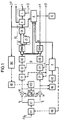
- FIG. 1 The block diagram of a receiver for two- and four-stage digitally modulated signals for use in mobile communication systems is shown in FIG. 1.
- the first exemplary embodiment is explained on the basis of this figure with an inserted explanation of FIGS. 2-4 and with tables. It is a homodyne, incoherent, digital vector receiver with a mixing stage. Analog signal paths are identified as a single line, digital data paths as a double line. The rule branches are dashed accordingly.
- a preamplifier VV connected to an antenna A raises the input level with little noise and intermodulation and at the same time decouples antenna A from the inputs of the mixer.
- This high-frequency pre-stage contains only a fixed, rough pre-selection of the input frequency range.
- the preamplifier VV is equipped with a controllable gain to enable partial input dynamic compensation.
- the input signal is converted in one step from the reception frequency f E , approximately 2 GHz, to a baseband.
- the received signal be broken down into real and imaginary parts. This is done by means of a quadrature demodulator, which consists of a power divider LT and two identical mixers M, which are fed with a 0 ° and a 90 ° phase-shifted signal from a local oscillator VCO with an oscillator frequency f LO .
- the local oscillator VCO is not frequency and phase locked to the input carrier frequency.
- a retuning input is provided for a rough frequency correction at the local oscillator VCO.
- the retuning voltage is determined in an offset correction device OKE.
- the frequency difference between the reception frequency f E and the oscillator frequency f LO should not be more than 5 ppm.
- Two linear low-pass filters TP effect the main selection of the receiver. They contain DC voltage isolating capacitors to suppress DC voltage components of the useful signal and therefore act like broadband bandpass filters.
- the gain of the individual filter stages can be adjusted digitally, so that dynamic compensation can also be carried out here. Behind the filter stages are the real and imaginary parts of the received signal in band-limited, amplitude and time continuous form.
- the signals in the real and imaginary branches are periodically sampled by sample-and-hold elements SH with a system clock ST and digitized in two analog / digital converters AD. Due to the dynamic compensation on the preamplifier VV and on the low-pass TP, the dynamic fluctuations are limited to a few dB and a resolution of the analog / digital converter AD of 5 - 8 bits is sufficient.
- the system clock ST is generated by a clock generator TG and has a frequency of 8.8 MHz. Thereafter, the real and imaginary parts of the input signal are available as binary numerical values at all times.
- the data rate is 1.1 Mbit / sec with a data clock DT of 1.1 MHz, which means that the system clock ST achieves 8 times oversampling.
- a conversion table in permanent memories ROM converts the real and imaginary parts into the amount and angle of a complex vector.
- the numerical values for the real and imaginary parts form the data addresses of the permanent memory ROM, the absolute value B and the angular value W are obtained at the data output.
- the amount B is used to set the gain in the preamplifier VV and in the low-pass filters TP of the main selection.
- the angle information is coded so that N bits with a value set of 2 N correspond to the full angle of 360 ° (see Table 1). This coding allows binary angular addition and subtraction with the correct sign and two's complement beyond 360 °.
- a subtractor SB forms the difference between the current angle value W and the angle value W of the previous sampling time stored in a buffer ZS.
- a classification of the amount depending on the chosen modulation method the angle difference ⁇ in the decryption areas E (Table 2) then delivers demodulated received data D, the sampling time of which is determined in an adjusting device JE.
- a classifier K and a latch L are connected to the subtractor SB to form a decoder DC. The value is selected from the latch L.
- the vector receiver can be automatically converted to different modulation methods by a post-microcomputer. This enables the construction of a multi-standard device.
- ⁇ E means the angle of a decision area E and T bit the bit duration, which is the reciprocal of the data take DT.
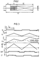
- a synchronization sequence for determining the sampling time must be sent at the beginning of each reception sequence ES. This is initiated by briefly blanking out the transmission signal. This results in the time structure of the received signal with blanking time AZ, synchronization time SZ and bit transmission time BZ.
- the stability of the send and receive data clock and the fineness of the time resolution for the sampling within one bit determine the time at which the sampling time is then valid.
- Different synchronization methods are used to determine the sampling time for the linear and non-linear modulation methods.
- MSK, GMSK nonlinear modulation method
- the amount of the vector is constant in the case of nonlinear modulation methods (constant envelope).
- the phase shift PHD increases continuously as a result of the carrier frequency offset.
- a phase difference PD can be formed by 8 times oversampling and formation of a phase difference with the value 1 bit ahead of each sampling time within a bit.
- Their angle sign function WVF corresponds to the synchronization sequence SF shifted by T bit / 2.
- a modulation with the synchronization sequence SF can be used to generate a zero-crossing of the received signal at periodic intervals, as shown in FIG. 4 for linear amplitude modulation with suppressed carrier.
- the course of the carrier frequency offset ⁇ f and the course of the real and imaginary part RT, IT of the received signal are shown.
- the amount of the vector is variable with linear modulation methods.
- narrow pulses are generated by means of digital differentiation at the time of the zero crossing. They form a zero pulse sequence NF.
- the automatic gain control is a controller R implemented in digital technology, shown in Fig. 1. It has the task to keep the signal level fluctuating during operation with a constant modulation of the analog / digital converter AD to a few dB.
- the absolute value B formed in the permanent memory ROM is read into the controller R as the actual level.
- the controller R must work so slowly that it cannot follow the brief level drops before the synchronization times.
- the non-band-limited signal power present after the mixers M is used as a parameter for distributing the amplification to the RF pre-stage and the main selection stages.
- the parameter is determined by forming the amount of the reception vector in a normalization device NV.
- FIG. 5 shows the schematic block diagram of a heterodyne vector receiver as a second exemplary embodiment. It works like the vector receiver of the first embodiment with incoherent demodulation.
- the signal received via antenna A is reduced from 60 GHz to 2 GHz via an intermediate frequency converter ZFU.
- a vector receiver which is constructed as in the first exemplary embodiment, can thus be used in module technology for the reception of satellite signals.
- the processing of the received signal from the preamplifier VV remains the same.
- the intermediate frequency converter ZFU contains an input amplifier EV, which is followed by a premixer VM.
- the premixer VM is connected to an intermediate frequency oscillator ZFO.
Abstract
Description
Die Erfindung betrifft ein Verfahren zum Umsetzen eines digital modulierten Empfangssignals aus dem Hochfrequenzbereich, wobei das als komplexer Vektor darstellbare Empfangssignal in mindestens einer Mischstufe inkohärent ins Basisband umgesetzt wird. Die Erfindung betrifft weiters einen Empfänger für digital modulierte Signale in einem mobilen Kommunikationssystem, dessen Antenne mit mindestens einer Mischstufe für das als komplexer Vektor darstellbare Empfangssignal verbunden ist, wobei der Mischstufe zwei Tiefpaßfilter nachgeordnet sind, die ausgangsseitig über je einen Analog/Digital-Wandler mit einem Umwerter verbunden sind.The invention relates to a method for converting a digitally modulated received signal from the radio frequency range, the received signal, which can be represented as a complex vector, being incoherently converted to the baseband in at least one mixing stage. The invention further relates to a receiver for digitally modulated signals in a mobile communication system, the antenna of which is connected to at least one mixing stage for the reception signal which can be represented as a complex vector, the mixing stage being followed by two low-pass filters, each of which has an analog / digital converter on the output side a corrector.
Ein nach einem derartigen Verfahren arbeitender Empfänger ist aus der WO 86/3356 bekannt. Das Empfangssignal wird von zwei Mischern mit einem Lokaloszillator phasenrichtig und um 90° phasenverschoben umgesetzt. Tiefpaßfiltern und Analog-Digital/Wandlern ist ein digitales Filter nachgeschaltet. Die Decodierung der übertragenen Bits erfolgt mit einem als Umwerter arbeitenden ROM, dem ein Multiplexer nachgeschaltet ist (Fig. 17).A receiver working according to such a method is known from WO 86/3356. The received signal is converted by two mixers with a local oscillator in the correct phase and out of phase by 90 °. Low-pass filters and analog-digital / converters are followed by a digital filter. The transmitted bits are decoded using a ROM operating as a corrector, followed by a multiplexer (FIG. 17).
Ein Empfangsverfahren und ein Empfänger für Schnurlos-Telefone wird im Telcom Report 10 (1987), Heft 2, Seite 130 bis 137, beschrieben. Das Empfangssignal wird über eine Hochfrequenzstufe und mehrere Zwischenfrequenzstufen in das Basisband gemischt. Die Demodulation erfolgt mit PLL-Schaltung.A reception method and a receiver for cordless telephones is described in Telcom Report 10 (1987), No. 2, pages 130 to 137. The received signal is mixed into the baseband via a high frequency stage and several intermediate frequency stages. Demodulation is carried out using a PLL circuit.
Im allgemeinen werden digital modulierte Signale durch synchrone oder, seltener, asynchrone Heterodynempfänger verarbeitet. Eine Spiegelfrequenzunterdrückung erfolgt in der Hochfrequenzstufe, die Hauptselektion in ein bis zwei Zwischenfrequenzstufen. Begrenzerverstärker oder Verstärkungsregelungen schaffen den notwendigen Ausgleich der Eingangsdynamik. Lineare Modulationsverfahren unterteilen sich in zweistufige Verfahren mit binärer Amplitudenmodulation (BAM) und binärem Phase-Shift-Keying (BPSK), vierstufige Verfahren mit Quadratur-Amplitudenmodulation (QAM) und Quadratur-Phase-Shift-Keying (QPSK), sowie mehrstufige Modifikationen. Als nichtlineare Modulationsverfahren sind FSK- oder frequenzmodulationsähnliche Verfahren, wie Minimum-Shift-Keying (MSK) und gaußgefiltertes Minimum-Shift-Keying (GMSK) gebräuchlich. Die Demodulation erfolgt für nichtlineare Modulationsverfahren mittels PLL, Costas-Loop oder Diskriminatoren. Für lineare Modulationsverfahren werden synchrone Quadraturdemodulatoren verwendet.In general, digitally modulated signals are processed by synchronous or, more rarely, asynchronous heterodyne receivers. An image frequency suppression takes place in the high frequency stage, the main selection in one or two intermediate frequency stages. Limiter amplifiers or gain controls create the necessary balance of the input dynamics. Linear modulation methods are divided into two-stage procedures with binary amplitude modulation (BAM) and binary phase shift keying (BPSK), four-stage procedures with quadrature amplitude modulation (QAM) and quadrature phase shift keying (QPSK), as well as multi-stage modifications. FSK or frequency modulation-like methods, such as minimum shift keying (MSK) and Gaussian-filtered minimum shift keying (GMSK), are common as nonlinear modulation methods. Demodulation takes place for non-linear modulation methods using PLL, Costas loop or discriminators. Synchronous quadrature demodulators are used for linear modulation methods.
Der Erfindung liegt die Aufgabe zugrunde, die Verarbeitung zwei- und mehrstufig digital modulierter Signale mit einem Empfänger zu ermöglichen.The invention has for its object to enable the processing of two- and multi-stage digitally modulated signals with a receiver.
Dies wird gemäß Patentanspruch 1 dadurch erreicht, daß das Empfangssignal in einen zeit- und amplitudenkontinuierlichen Real- und Imaginärteil zerlegt wird, wobei die Phasendifferenz pro Bitdauer durch die inkohärente Umsetzung kleiner als die halbe, durch die Modulation pro Bit verursachte Phasenverschiebung gehalten wird, die Signalteile anschließend verstärkt, gefiltert und abgetastet werden, wobei innerhalb einer vorangehenden Synchronisationszeit der Abtastzeitpunkt bestimmt wird, anschließend die Abtastsignale digitalisiert und die Abtastwerte als binäres Zahlenpaar für Betrag und Winkel des Vektors umgewerter werden, wobei der Betragswert zur Verstärkungsregelung dient und aus der Differenz zweier aufeinanderfolgender Winkelwerte nach Klassierung Empfangsdaten rückgewonnen werden.This is achieved according to claim 1 in that the received signal in a time and amplitude-continuous real and imaginary part is broken down, the phase difference per bit duration being kept smaller than half the phase shift caused by the modulation per bit due to the incoherent conversion, the signal parts are then amplified, filtered and sampled, the sampling time being determined within a preceding synchronization time is then digitized the scanning signals and the samples are converted as a binary pair of numbers for the magnitude and angle of the vector, the magnitude value being used for gain control and received data from the difference between two successive angle values after classification.
Durch eine homodyne Arbeitsweise wird das Auftreten einer Spiegelfrequenz vermieden. Die inkohärente Demodulation vermeidet aufwendige Trägersynchronisation und erlaubt gleichspannungsfreie Signalpfade. Die Phasendifferenz wird durch Frequenzkorrektur oder Oszillatoren mit exakter Frequenzkonstanz gering gehalten. Trotz der Verwendung nur einer Mischstufe sind mit diesem Empfangsverfahren fast alle zwei- und mehrstufigen, linearen und nichtlinearen Modulationsverfahren einsetzbar.A homodyne mode of operation prevents the occurrence of an image frequency. The incoherent demodulation avoids complex carrier synchronization and allows DC voltage-free signal paths. The phase difference is kept low by frequency correction or oscillators with exact frequency constancy. Despite the use of only one mixing stage, almost all two- and multi-stage, linear and non-linear modulation methods can be used with this reception method.
Eine effiziente Winkeldecodierung über 360° hinaus wird dadurch erreicht, daß ein Winkelwert über eine Bitdauer zwischengespeichert, von dem folgenden im Zweierkomplement subtrahiert und aus einer vom verwendeten Modulationsverfahren abhängigen Klassierung des Ergebnisses die Empfangsdaten rückgewonnen werden. Die Anpassung an das individuelle Modulationsverfahren erfolgt über eine programmierbare Einstellung der Klassierung, wodurch keine Schaltungsänderung notwendig wird.Efficient angle decoding beyond 360 ° is achieved by temporarily storing an angle value over a bit period, subtracting it from the following in two's complement and recovering the received data from a classification of the result which is dependent on the modulation method used. The adaptation to the individual modulation process is done via a programmable setting of the classification, which means that no circuit change is necessary.
Es ist vorteilhaft, daß der Abtastzeitpunkt für den Winkelwert eines linear modulierten Empfangssignals innerhalb einer Synchronisationszeit vor der Übertragung gültiger Daten dadurch ermittelt wird, daß der Verlauf des Betrags des Empfangssignals mit einer Synchronisationsfolge moduliert und nach Umsetzen ins Basisband die Vorzeichenfunktion gebildet und diese digital differenziert wird, wobei eine Nullstellenimpulsfolge gebildet, die zeitliche Lage der Impulse relativ zum Systemtakt gemessen und über mehrere Bits gemittelt wird. Aus der Drehung des Vektors des Empfangssignals wird eine Korrektur der Phasendifferenz durch inkohärente Umsetzung abgeleitet.It is advantageous that the sampling time for the angle value of a linearly modulated received signal is determined within a synchronization time before the transmission of valid data in that the course of the amount of the received signal modulated with a synchronization sequence and after conversion to the baseband the sign function is formed and this is digitally differentiated, whereby a zero pulse sequence is formed, the temporal position of the pulses is measured relative to the system clock and is averaged over several bits. A correction of the phase difference by incoherent conversion is derived from the rotation of the vector of the received signal.
Weiters ist es vorteilhaft, daß der Abtastzeitpunkt für den Winkelwert eines nichtlinearen modulierten Empfangssignals innerhalb einer Synchronisationszeit vor der Übertragung gültiger Daten dadurch ermittelt wird, daß der mit der Synchronisationsfolge winkelmodulierte Träger nach Umsetzung ins Basisband überabgetastet und daraus ein Phasenhub gewonnen wird, wobei aus diesem durch Differenzbildung über eine Bitdauer eine Phasendifferenz gebildet wird, deren Winkelvorzeichenfunktion phasenmäßig mit dem Datentakt verglichen und die Phasenverschiebung über mehrere Bits gemittelt wird.Furthermore, it is advantageous that the sampling time for the angle value of a nonlinear modulated received signal is determined within a synchronization time before the transmission of valid data by over-sampling the angle-modulated carrier with the synchronization sequence after conversion to the baseband and a phase shift being obtained therefrom Difference formation over a bit duration, a phase difference is formed, the phase sign function of which is compared in phase with the data clock and the phase shift is averaged over several bits.
Die Aufgabe der Erfindung wird gemäß Patentanspruch 5 auch dadurch gelöst, daß die Tiefpaßfilter mit regelbarer Verstärkung ausgestattet sind, daß der Umwerter Mittel zur Bestimmung von Betrag und Winkel des Vektors des Empfangssignals aus dessen Real- und Imaginärteil enthält und zur Empfangsdatenrückgewinnung mit einem Decoder verbunden ist, der einen Klassifikator enthält und daß eine Justiereinrichtung zur Ermittlung des Abtastzeitpunktes mit dem Umwerter und dem Decoder verbunden ist.The object of the invention is also achieved according to claim 5 in that the low-pass filters are equipped with adjustable gain, that the converter contains means for determining the amount and angle of the vector of the received signal from its real and imaginary parts and is connected to a decoder for receiving data recovery , which contains a classifier and that an adjustment device for determining the sampling time is connected to the corrector and the decoder.
Durch die Umsetzung ins Basisband mit einer Mischstufe wird Hochfrequenz-Schaltungsaufwand eingespart. Nach der Hochfrequenz-Vorstufe sind die Schaltungskomponenten in Si-Bipolar- oder MOS-Technologie voll integrierbar. Es müssen keine Hochfrequenz- oder Zwischenfrequenz-Stufen mehr abgeglichen werden. Das Regelverhalten der digitalen Amplitudenregelung ist programmierbar und ohne Schaltungsänderung veränderbar. Durch die Tiefpaßfilter werden unerwünschte Signalkomponenten entfernt.The implementation in the baseband with a mixer saves high-frequency circuitry. After the high-frequency pre-stage, the circuit components can be fully integrated in Si bipolar or MOS technology. No high frequency or intermediate frequency levels can be adjusted more. The control behavior of the digital amplitude control is programmable and can be changed without changing the circuit. The low-pass filter removes unwanted signal components.
Es ist vorteilhaft, daß die Mischstufe als Quadraturdemodulator ausgebildet ist, der aus zwei Mischern besteht, die mit einem Lokaloszillator zur Speisung mit einem um 0°- und 90°-phasenverschobenen Oszillatorsignal verbunden sind und der Lokaloszillator einen Nachstimmeingang aufweist, der mit einer Offsetkorrektureinrichtung verbunden ist. Der Lokaloszillator ist mit dem Eingangssignal nicht phasenstarr gekoppelt, wodurch Schaltungsaufwand zur Synchronisation eingespart wird. Der Trägerfrequenz-Offset aus der Phasenverschiebung der Inkohärenz der Frequenz von Eingangssignal und Lokaloszillator wird über den Nachstimmeingang minimiert. Sein Wert ergibt sich bei der Ermittlung des Abtastzeitpunktes und muß nicht mehr zusetzlich berechnet werden.It is advantageous that the mixer stage is designed as a quadrature demodulator, which consists of two mixers which are connected to a local oscillator for feeding with an oscillator signal shifted by 0 ° and 90 ° and the local oscillator has a retuning input which is connected to an offset correction device is. The local oscillator is not phase-locked to the input signal, which saves circuitry for synchronization. The carrier frequency offset from the phase shift of the incoherence of the frequency of the input signal and local oscillator is minimized via the retuning input. Its value results from the determination of the sampling time and no longer has to be calculated additionally.
Es ist vorteilhaft, daß der Verstärkungsfaktor der Tiefpaßfilter digital einstellbar und der Umwerter zu dieser Regelung mit den Tiefpaßfiltern rückgekoppelt ist. Zur Beseitigung von Gleichspannungsanteilen enthalten die Tiefpaßfilter Gleichspannungstrennkondensatoren. Sie wirken daher wie Bandpaßfilter mit einer Breite von mehreren Dekaden.It is advantageous that the amplification factor of the low-pass filter can be adjusted digitally and the corrector for this regulation is fed back to the low-pass filter. To eliminate DC voltage components, the low-pass filters contain DC voltage isolation capacitors. They therefore act like bandpass filters with a width of several decades.
Zur Verringerung des Stromverbrauches und der Verarbeitung hoher Datenraten ist es vorteilhaft, daß der Umwerter aus zwei Permanentspeichern besteht, deren Datenadressen durch die Zahlenwerte für Real- und Imaginärteil der Abtastwerte gebildet sind und daß Betrags- und Winkelwert am Datenausgang des jeweiligen Permanentspeichers anliegen.To reduce the power consumption and the processing of high data rates, it is advantageous that the corrector consists of two permanent memories, the data addresses of which are formed by the numerical values for the real and imaginary part of the sampled values, and that the magnitude and angle values are present at the data output of the respective permanent memory.
Um die Demodulation des Empfangssignals auf extrem hohe Frequenzen erweitern zu können ist es vorteilhaft, daß der Mischstufe mindestens ein Zwischenfrequenzumsetzer vorgeschaltet ist. Der Anwendungsbereich des Empfängers wird dadurch erweitert, daß er durch unterschiedliche Zwischenfrequenzumsetzer an unterschiedliche Empfangsfrequenzen anpaßbar ist.In order to be able to extend the demodulation of the received signal to extremely high frequencies, it is advantageous that at least one intermediate frequency converter is connected upstream of the mixing stage is. The field of application of the receiver is expanded in that it can be adapted to different reception frequencies by means of different intermediate frequency converters.
Die Erfindung wird anhand zweier Ausführungsbeispiele und von Zeichnungen näher erläutert. Es zeigen:
- Fig. 1
- ein Blockschaltbild des ersten Ausführungsbeispieles,
- Fig. 2
- die Zeitstruktur des Empfangssignals,
- Fig. 3
- den Phasenverlauf bei Winkelmodulation zur Ermittlung des Abtastzeitpunktes und
- Fig. 4
- den Signalverlauf zur Emittlung des Abtastzeitpunktes bei linearen Modulationsverfahren,
- Fig. 5
- ein Blockschaltbild des zweiten Ausführungsbeispieles.
- Fig. 1
- 2 shows a block diagram of the first exemplary embodiment,
- Fig. 2
- the time structure of the received signal,
- Fig. 3
- the phase curve with angular modulation to determine the sampling time and
- Fig. 4
- the signal curve for determining the sampling time in the case of linear modulation methods,
- Fig. 5
- a block diagram of the second embodiment.
Das Blockschaltbild eines Empfängers für zwei- und vierstufig digital modulierte Signale zum Einsatz in mobilen Kommunikationssystemen ist in Fig. 1 dargestellt. Das erste Ausführungsbeispiel wird anhand dieser Fig. mit eingeschobener Erklärung der Figuren 2 - 4 und mit Tabellen erläutert. Es handelt sich um einen homodynen, inkohärenten, digitalen Vektorempfänger mit einer Mischstufe. Analoge Signalwege sind als einfacher Strich, digitale Datenwege als doppelter Strich gekennzeichnet. Die Regelzweige sind entsprechend strichliert.The block diagram of a receiver for two- and four-stage digitally modulated signals for use in mobile communication systems is shown in FIG. 1. The first exemplary embodiment is explained on the basis of this figure with an inserted explanation of FIGS. 2-4 and with tables. It is a homodyne, incoherent, digital vector receiver with a mixing stage. Analog signal paths are identified as a single line, digital data paths as a double line. The rule branches are dashed accordingly.
Ein mit einer Antenne A verbundener Vorverstärker VV hebt den Eingangspegel rausch- und intermodulationsarm an und bewirkt gleichzeitig eine Entkopplung der Antenne A von den Eingängen der Mischstufe. Diese Hochfrequenz-Vorstufe enthält nur eine fixe, grobe Vorselektion des Eingangsfrequenzbereiches. Außerdem ist der Vorverstärker VV mit einer regelbaren Verstärkung ausgestattet, um einen teilweisen Eingangsdynamikausgleich zu ermöglichen.A preamplifier VV connected to an antenna A raises the input level with little noise and intermodulation and at the same time decouples antenna A from the inputs of the mixer. This high-frequency pre-stage contains only a fixed, rough pre-selection of the input frequency range. In addition, the preamplifier VV is equipped with a controllable gain to enable partial input dynamic compensation.
In der Mischstufe wird das Eingangssignal in einem Schritt von der Empfangsfrequenz fE, etwa 2 GHz, in ein Basisband umgesetzt. Um den vollen Informationsgehalt zu bewahren, muß das Empfangssignal in Real- und Imaginärteil zerlegt werden. Dies geschieht mittels eines Quadraturdemodulators, der aus einem Leistungsteiler LT und aus zwei gleichartigen Mischern M besteht, die mit einem 0°- und einem 90°-phasenverschobenen Signal eines Lokaloszillators VCO mit einer Oszillatorfrequenz fLO angespeist werden.In the mixer stage, the input signal is converted in one step from the reception frequency f E , approximately 2 GHz, to a baseband. In order to preserve the full information content, the received signal be broken down into real and imaginary parts. This is done by means of a quadrature demodulator, which consists of a power divider LT and two identical mixers M, which are fed with a 0 ° and a 90 ° phase-shifted signal from a local oscillator VCO with an oscillator frequency f LO .
Der Lokaloszillator VCO ist mit der Eingangsträgerfrequenz nicht frequenz- und phasenstarr gekoppelt. Um einen Trägerfrequenz-Offset zwischen der Empfangsfrequenz fE und der Oszillatorfrequenz fLO möglichst klein zu halten, ist ein Nachstimmeingang für eine grobe Frequenzkorrektur am Lokaloszillator VCO vorgesehen. Die Nachstimmspannung wird in einer Offsetkorrektureinrichtung OKE ermittelt. Der Frequenzunterschied zwischen Empfangsfrequenz fE und Oszillatorfrequenz fLO sollte aber nicht mehr als 5 ppm betragen.The local oscillator VCO is not frequency and phase locked to the input carrier frequency. In order to keep a carrier frequency offset between the reception frequency f E and the oscillator frequency f LO as small as possible, a retuning input is provided for a rough frequency correction at the local oscillator VCO. The retuning voltage is determined in an offset correction device OKE. However, the frequency difference between the reception frequency f E and the oscillator frequency f LO should not be more than 5 ppm.
Nach den Mischern M liegt das Nutzsignal, von Rauschen und Nachbarkanalsignalen überlagert, im Basisband vor. Zwei laufzeitlineare Tiefpaßfilter TP bewirken die Hauptselektion des Empfängers. Sie enthalten Gleichspannungstrennkondensatoren zur Unterdrückung von Gleichspannungsanteilen des Nutzsignals und wirken daher wie breitbandige Bandpaßfilter. Die Verstärkung der einzelnen Filterstufen ist digital einstellbar, so daß auch hier ein Dynamikausgleich durchgeführt werden kann. Hinter den Filterstufen liegen Real- und Imaginärteil des Empfangssignals in bandbegrenzter, amplituden- und zeitkontinuierlicher Form vor.After the mixers M, the useful signal, superimposed by noise and adjacent channel signals, is present in the baseband. Two linear low-pass filters TP effect the main selection of the receiver. They contain DC voltage isolating capacitors to suppress DC voltage components of the useful signal and therefore act like broadband bandpass filters. The gain of the individual filter stages can be adjusted digitally, so that dynamic compensation can also be carried out here. Behind the filter stages are the real and imaginary parts of the received signal in band-limited, amplitude and time continuous form.
Nach den Tiefpaßfiltern TP werden die Signale im Real- und Imaginär-Zweig durch Abtast-Halteglieder SH mit einem Systemtakt ST periodisch abgetastet und in zwei Analog/Digital-Wandlern AD digitalisiert. Durch den Dynamikausgleich am Vorverstärker VV und an den Tiefpässen- TP sind die Dynamikschwankungen auf einige dB beschränkt und eine Auflösung der Analog/Digital-Wandler AD von 5 - 8 Bit ausreichend. Der Systemtakt ST wird von einem Taktgenerator TG erzeugt und hat eine Frequenz von 8,8 MHz. Danach liegen Real- und Imaginärteil des Eingangssignals zu jedem Zeitpunkt als binäre Zahlenwerte vor. Die Datenrate beträgt 1,1 MBit/sek bei einem Datentakt DT von 1,1 MHz, womit durch den Systemtakt ST ein 8-faches Oversampling erzielt wird.After the low-pass filters TP, the signals in the real and imaginary branches are periodically sampled by sample-and-hold elements SH with a system clock ST and digitized in two analog / digital converters AD. Due to the dynamic compensation on the preamplifier VV and on the low-pass TP, the dynamic fluctuations are limited to a few dB and a resolution of the analog / digital converter AD of 5 - 8 bits is sufficient. The system clock ST is generated by a clock generator TG and has a frequency of 8.8 MHz. Thereafter, the real and imaginary parts of the input signal are available as binary numerical values at all times. The data rate is 1.1 Mbit / sec with a data clock DT of 1.1 MHz, which means that the system clock ST achieves 8 times oversampling.
Da die empfangene Information als Winkeldifferenz zwischen Abtastzeitpunkten codiert ist, werden mit einer Umwertetabelle in Permanentspeichern ROM Real- und Imaginärteil in Betrag und Winkel eines komplexen Vektors umgerechnet. Die Zahlenwerte für Real- und Imaginärteil bilden die Datenadressen der Permanentspeicher ROM, Betragswert B und Winkelwert W erhält man am Datenausgang. Der Betragswert B wird zur Einstellung der Verstärkung im Vorverstärker VV und in den Tiefpaßfiltern TP der Hauptselektion verwendet. Die Winkelinformation wird so codiert, daß N Bit mit einem Wertevorrat von 2N dem vollen Winkel von 360° entsprechen (siehe Tabelle 1). Diese Codierung erlaubt vorzeichenrichtige, binäre Winkeladdition und -subtraktion mit Zweierkomplement über 360° hinaus.

Ein Subtrahierer SB bildet die Differenz zwischen dem aktuellen Winkelwert W und dem in einem Zwischenspeicher ZS gespeicherten Winkelwert W des vorangegangenen Abtastzeitpunktes. Eine vom gewählten Modulationsverfahren abhängige Klassierung des Betrages der Winkeldifferenz Δφ in Entscneidungsgebiete E (Tabelle 2) liefert dann demodulierte Empfangsdaten D, deren Abtastzeitpunkt in einer Justiereinrichtung JE ermittelt wird. Dazu ist ein Klassifikator K und ein Haltespeicher L mit dem Subtrahierer SB zu einem Decoder DC verbunden. Aus dem Haltespeicher L wird der Wert ausgewählt. Aufgrund der Entscheidungsgebiete E kann der Vektorempfänger von einem nachgeodneten Mikrocomputer selbsttätig auf unterschiedliche Modulationsverfahren umgestellt werden. Das ermöglicht den Aufbau eines Mehrnormengerätes.

Damit durch den Klassifikator K eine richtige Zuordnung möglich ist, muß die Phasenverschiebung, die durch die Inkohärenz von Eingangssignal und Lokaloszillator VCO pro Bit entsteht, kleiner als der halbe Winkel eines Entscheidungsgebietes E sein. Daraus folgt die maximal zulässige Frequenzdifferenz fO,max zwischen Empfangssignal und Lokaloszillatorsignal zu![]()
In der Gleichung bedeuten ΔφE den Winkel eines Entscheidungsgebietes E und Tbit die Bitdauer, die der Reziprokwert des Datentakes DT ist.In order for a correct assignment to be possible using the classifier K, the phase shift which arises from the incoherence of the input signal and the local oscillator VCO per bit must be less than half the angle of a decision area E. From this follows the maximum permissible frequency difference f O, max between the received signal and the local oscillator signal ![]()
In the equation, Δφ E means the angle of a decision area E and T bit the bit duration, which is the reciprocal of the data take DT.
Aufgrund der Frequenzdifferenz zwischen Eingangsfrequenz fE und Oszillatorfrequenz fLO sind die Winkeldifferenzen![]()
für Modulation mit positiver und negativer Phasenverschiebung Δφ bit nicht symmetrisch. Durch die Offsetkorrektureinrichtung OKE wird aus der Differenz der Phasenhübe der Trägerfrequenz-Offset Δf als![]()
errechnet. Bei bekannter Spannungsabhängigkeit der Frequenz des Lokaloszillators VCO wird ein Frequenzkorrektursignal als Nachstimmspannung abgeleitet.The angle differences are due to the frequency difference between the input frequency f E and the oscillator frequency f LO ![]()
for modulation with positive and negative phase shift Δφ bit not symmetrical. By means of the offset correction device OKE, the carrier frequency offset Δf is made from the difference of the phase shifts ![]()
calculated. If the frequency dependence of the frequency of the local oscillator VCO is known, a frequency correction signal is derived as the tuning voltage.
Wie Fig. 2 zeigt, muß zu Beginn jeder Empfangssequenz ES eine Synchronisationsfolge zur Bestimmung des Abtastzeitpunktes gesendet werden. Diese wird durch ein kurzzeitiges Austasten des Sendesignals eingeleitet. Daraus ergibt sich die Zeitstruktur des Empfangssignals mit Austastzeit AZ, Synchronisationszeit SZ und Bitübertragungszeit BZ. Über welche Zeit der Abtastzeitpunkt dann gültig ist, ist durch die Stabilität des Sende- und des Empfangsdatentaktes, sowie die Feinheit der Zeitauflösung für die Abtastung innerhalb eines Bits gegeben. Die Anzahl N der gültig empfangenen Bits ergibt sich als![]()
wobei Δftakt,max die maximale Taktfrequenzdifferenz zwischen Sender und Empfänger und OV (Oversampling) die Zahl der möglichen Abtastzeitpunkte pro Bit ist. Nach maximal N Datenbits muß eine neuerliche Synchronisationsfolge gesendet werden, damit der Empfänger den Abtastzeitpunkt aktualisieren kann. Bei OV = 8 und einem auf 50 ppm genauen Datentakt (Δftakt,max = = 50.10⁻⁶) und Tbit = 909,1.10⁻⁹ sec ergeben sich 1250 gültig empfangene Bits (N).As shown in FIG. 2, a synchronization sequence for determining the sampling time must be sent at the beginning of each reception sequence ES. This is initiated by briefly blanking out the transmission signal. This results in the time structure of the received signal with blanking time AZ, synchronization time SZ and bit transmission time BZ. The stability of the send and receive data clock and the fineness of the time resolution for the sampling within one bit determine the time at which the sampling time is then valid. The number N of validly received bits is given as ![]()
where Δf clock , max is the maximum clock frequency difference between transmitter and receiver and OV (oversampling) is the number of possible sampling times per bit. After a maximum of N data bits, a new synchronization sequence must be sent so that the receiver can update the sampling time. With OV = 8 and a data clock accurate to 50 ppm (Δf clock, max = = 50.10⁻⁶) and T bit = 909.1.10,1 sec, there are 1250 validly received bits (N).
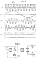
Für die linearen und nichtlinearen Modulationsverfahren werden verschiedene Synchronisationsmethoden zur Bestimmung des Abtastzeitpunktes verwendet. Bei den nichtlinearen Modulationsverfahren (MSK, GMSK), wie in Fig. 3 für MSK gezeigt, kann man durch Modulation mit einer, einer Datenfolge d(t) = +1,-1,+1, -1,+1... entsprechenden, Synchronisationsfolge SF einen periodischen Phasenhub PH erzeugen. Der Betrag des Vektors ist bei nichtlinearen Modulationsverfahren konstant (const. Einhüllende). Bei der Demodulation steigt der Phasenhub PHD in Folge des Trägerfrequenzoffsets stetig an. Durch 8-fache Überabtastung und Phasendifferenzbildung mit dem, um 1 Bit vorherliegenden Wert zu jedem Abtastzeitpunkt innerhalb eines Bits kann eine Phasendifferenz PD gebildet werden. Deren Winkelvorzeichenfunktion WVF entspricht der um Tbit/2 verschobenen Synchronisationsfolge SF. Durch Phasenvergleich mit dem Datentakt DT und zeitliche Mittelwertbildung kann daraus der Abtastzeitpunkt, auch bei verrauschten Eingangsverhältnissen, sehr genau bestimmt werden.Different synchronization methods are used to determine the sampling time for the linear and non-linear modulation methods. In the nonlinear modulation method (MSK, GMSK), as shown in FIG. 3 for MSK, one can, by modulation with a, a data sequence d (t) = + 1, -1, + 1, -1, + 1 ... corresponding, synchronization sequence SF generate a periodic phase shift PH. The amount of the vector is constant in the case of nonlinear modulation methods (constant envelope). During demodulation, the phase shift PHD increases continuously as a result of the carrier frequency offset. A phase difference PD can be formed by 8 times oversampling and formation of a phase difference with the value 1 bit ahead of each sampling time within a bit. Their angle sign function WVF corresponds to the synchronization sequence SF shifted by T bit / 2. By comparing the phases with the data clock DT and averaging over time, the sampling time can be determined very precisely, even with noisy input conditions.
Bei den linearen Modulationsverfahren (BAM,BPSK,QAM,QPSK) kann man durch Modulation mit der Synchronisationsfolge SF einen datentaktperiodischen Nulldurchgang des Empfangssignals erzeugt, wie in Fig. 4 für lineare Amplitudenmodulation mit unterdrücktem Träger gezeigt ist. Es wird der Verlauf des Trägerfrequenz-Offsets Δf, sowie der Verlauf des Real- und Imaginärteiles RT, IT des Empfangssignals gezeigt. Der Betrag des Vektors ist bei linearen Modulationsverfahren variabel. Nach Bildung der Vorzeichenfunktion VZF des Real- und Imaginärteils RT, IT werden mittels digitaler Differentiation zum Zeitpunkt des Nulldurchgangs schmale Impulse erzeugt. Sie bilden eine Nullstellenpulsfolge NF. Durch Messung der zeitlichen Lage der Impulse relativ zum Systemtakt und Mittelwertbildung über einige Bits, erhält man auch bei verrauschten Empfangsverhältnissen den Abtastzeitpunkt mit hoher Zuverlässigkeit.In the case of the linear modulation methods (BAM, BPSK, QAM, QPSK), a modulation with the synchronization sequence SF can be used to generate a zero-crossing of the received signal at periodic intervals, as shown in FIG. 4 for linear amplitude modulation with suppressed carrier. The course of the carrier frequency offset Δf and the course of the real and imaginary part RT, IT of the received signal are shown. The amount of the vector is variable with linear modulation methods. After the sign function VZF of the real and imaginary part RT, IT has been formed, narrow pulses are generated by means of digital differentiation at the time of the zero crossing. They form a zero pulse sequence NF. By measuring the temporal position of the pulses relative to the system clock and averaging over a few bits, the sampling time is obtained with high reliability even with noisy reception conditions.
Die automatische Verstärkungsregelung ist ein in Digitaltechnik ausgeführter Regler R, gezeigt in Fig. 1. Er hat die Aufgabe, den im Betrieb schwankenden Signalpegel bei mittlerer Aussteuerung der Analog/Digital-Wandler AD auf einige dB konstant zu halten. Als Pegel-Istwert wird der im Permanentspeicher ROM gebildete Betragswert B in den Regler R eingelesen. Der Regler R muß so langsam arbeiten, daß er den kurzzeitigen Pegeleinbrüchen vor den Synchronisationszeiten nicht folgen kann. Zur Verringerung von Intermodulationsstörungen wird die, nach den Mischern M vorliegende, nicht bandbegrenzte Signalleistung als Parameter zur Aufteilung der Verstärkung auf die HF-Vorstufe und die Hauptselektionsstufen herangezogen. Der Parameter wird durch Betragsbildung des Empfangsvektors in einer Normiervorrichtung NV ermittelt.The automatic gain control is a controller R implemented in digital technology, shown in Fig. 1. It has the task to keep the signal level fluctuating during operation with a constant modulation of the analog / digital converter AD to a few dB. The absolute value B formed in the permanent memory ROM is read into the controller R as the actual level. The controller R must work so slowly that it cannot follow the brief level drops before the synchronization times. To reduce intermodulation interference, the non-band-limited signal power present after the mixers M is used as a parameter for distributing the amplification to the RF pre-stage and the main selection stages. The parameter is determined by forming the amount of the reception vector in a normalization device NV.
Fig. 5 zeigt das schematische Blockschaltbild eines heterodynen Vektorempfängers als zweites Ausführungsbeispiel. Er arbeitet wie der Vektorempfänger des ersten Ausführungsbeispieles mit inkohärenter Demodulation. Das über die Antenne A empfangene Signal wird über einen Zwischenfrequenzumsetzer ZFU von 60 GHz auf 2 GHz heruntergesezt. Somit kann ein Vektorempfänger, der wie im ersten Ausführungsbeispiel aufgebaut ist, in Modultechnik für den Empfang von Satellitensignalen verwendet werden. Die Verarbeitung des Empfangssignals ab dem Vorverstärker VV bleibt gleich. Der Zwischenfrequenzumsetzer ZFU enthält einen Eingangsverstärker EV, dem ein Vormischer VM nachgeschaltet ist. Der Vormischer VM ist mit einem Zwischenfrequenzoszillator ZFO verbunden.5 shows the schematic block diagram of a heterodyne vector receiver as a second exemplary embodiment. It works like the vector receiver of the first embodiment with incoherent demodulation. The signal received via antenna A is reduced from 60 GHz to 2 GHz via an intermediate frequency converter ZFU. A vector receiver, which is constructed as in the first exemplary embodiment, can thus be used in module technology for the reception of satellite signals. The processing of the received signal from the preamplifier VV remains the same. The intermediate frequency converter ZFU contains an input amplifier EV, which is followed by a premixer VM. The premixer VM is connected to an intermediate frequency oscillator ZFO.
Claims (10)
- Method of converting a digitally modulated reception signal from the radio-frequency range, in which the reception signal, which can be represented as a complex vector, is converted incoherently into the baseband at at least one mixing stage, characterized in that the reception signal is split into a real component and in imaginary component, continuous in time and amplitude, the phase difference per bit period due to the incoherent conversion being kept to less than half the phase shift caused by the modulation per bit, the signal components are subsequently amplified, filtered and sampled, the sampling time being determined within a preceding synchronization time (SZ), the sampled signals are subsequently digitized and the sampled values are value-converted as a pair of binary numbers for the magnitude and angle fo the vector, the magnitude value (B) serving for gain control and reception data (D) being recovered from the difference between two successive angle values (W) after classification.
- Method according to Claim 1, characterized in that an angle value (W) is buffer-stored over a bit period, subtracted from the following value by twos complement and the reception data (D) recovered from a classification of the result dependent of the modulation method used.
- Method according to Claim 1 or 2, characterized in that the sampling time for the angle value (W) of a linearly modulated reception signal is determined within a synchronization time (SZ) before the transmission of valid data by the variation of the magnitude of the reception signal being modulated with a synchronization sequence (SF) and, after conversion into a baseband, the sign function (VZF) formed and digitally differentiated, a zero pulse sequence (NF) being formed, the timing of the pulses measured in relation to the system clock (ST) and averaged over several bits.
- Method according to Claim 1 or 2, characterized in that the sampling time for the angle value (W) of a non-linearly modulated reception signal is determined within a synchronization time (SZ) before the transmission of valid data by the carrier which has been angle-modulated with the synchronization sequence (SF) being oversampled after conversion into the baseband and from it a phase deviation (PH) obtained, from this a phase difference (PD) being formed by subtracting over a bit period, the angle sign function (WVF) of which phase difference is compared in terms of phase with the data clock (DT) and the phase shift averaged over several bits.
- Receiver for digitally modulated signals in a mobile communication system, the antenna (A) of which is connected to at least one mixing stage for the reception signal, which can be represented as a complex vector, the mixing stage being followed by two low-pass filters (TP), which are connected on the output side via an analogue/digital converter (AD) in each case to a value converter, characterized in that the low-pass filters (TP) are provided with variable gain, in that the value converter includes means for determining the magnitude and angle of the vector of the reception signal from its real component and its imaginary component and is connected to a decoder (DC), which contains a classifier (K), for reception data recovery, and in that an adjusting device (JE) is connected to the value converter and the decoder (DC) for determining the sampling time.
- Receiver according to Claim 5, characterized in that the mixing stage is designed as a quadrature demodulator, which comprises two mixers (M) which are connected to a local oscillator (VCO) for feeding with an oscillator signal phase-shifted by 0° and 90° and in that the local oscillator (VCO) has a tuning input, which is connected to an offset correction device (OKE).
- Receiver according to Claim 5 or 6, characterized in that the gain factor of the low-pass filters (TP) can be digitally set and the value converter is coupled back to the low-pass filters (TP) for this control.
- Receiver according to one of Claims 5 to 7, characterized in that the low-pass filters (TP) contain DC isolating capacitors.
- Receiver according to one of Claims 5 to 8, characterized in that the value converter comprises two permanent memories (ROM), the data addresses of which are formed by the numerical values of the real component and the imaginary component of the sampled values and in that the magnitude value (B) and the angle value (W) are available at the data output of the respective permanent memories (ROM).
- Receiver according to one of Claims 5 to 9, characterized in that the mixing stage is preceded by at least one intermediate-frequency converter (ZFU).
Applications Claiming Priority (3)
| Application Number | Priority Date | Filing Date | Title |
|---|---|---|---|
| AT1923/89 | 1989-08-11 | ||
| AT192389 | 1989-08-11 | ||
| PCT/EP1990/001305 WO1991002421A1 (en) | 1989-08-11 | 1990-08-08 | Process and device for converting digitally modulated high-frequency reception signals |
Publications (2)
| Publication Number | Publication Date |
|---|---|
| EP0486554A1 EP0486554A1 (en) | 1992-05-27 |
| EP0486554B1 true EP0486554B1 (en) | 1994-10-26 |
Family
ID=3523948
Family Applications (1)
| Application Number | Title | Priority Date | Filing Date |
|---|---|---|---|
| EP90912008A Expired - Lifetime EP0486554B1 (en) | 1989-08-11 | 1990-08-08 | Process and device for converting digitally modulated high-frequency reception signals |
Country Status (8)
| Country | Link |
|---|---|
| US (1) | US5402449A (en) |
| EP (1) | EP0486554B1 (en) |
| JP (1) | JP3088454B2 (en) |
| AT (1) | ATE113432T1 (en) |
| DE (1) | DE59007578D1 (en) |
| DK (1) | DK0486554T3 (en) |
| ES (1) | ES2063372T3 (en) |
| WO (1) | WO1991002421A1 (en) |
Cited By (1)
| Publication number | Priority date | Publication date | Assignee | Title |
|---|---|---|---|---|
| DE10120702A1 (en) * | 2001-04-27 | 2002-11-14 | Infineon Technologies Ag | RF receiver |
Families Citing this family (27)
| Publication number | Priority date | Publication date | Assignee | Title |
|---|---|---|---|---|
| GR900100865A (en) * | 1990-12-17 | 1992-11-23 | Siemens Ag | Method and apparatus for digital fomulated reception signals from the high frequency area |
| EP0522998A3 (en) * | 1991-07-09 | 1993-07-28 | Ascom Tech Ag | Method for estimating the frequency offset in a quadrature receiver |
| DE4223121A1 (en) * | 1992-07-14 | 1994-01-20 | Deutsche Aerospace | Method for carrier recovery in the demodulation of digitally modulated signals and arrangements for carrying out the method |
| US5263048A (en) * | 1992-07-24 | 1993-11-16 | Magnavox Electronic Systems Company | Narrow band interference frequency excision method and means |
| DE4237692C1 (en) * | 1992-11-07 | 1994-03-03 | Grundig Emv | Receiver for a digital broadcast signal |
| FI94818C (en) * | 1993-06-02 | 1995-10-25 | Nokia Telecommunications Oy | A method for demodulating a digitally modulated signal and a demodulator |
| US5617451A (en) | 1993-09-13 | 1997-04-01 | Matsushita Electric Industrial Co., Ltd. | Direct-conversion receiver for digital-modulation signal with signal strength detection |
| US5757857A (en) * | 1994-07-21 | 1998-05-26 | The Regents Of The University Of California | High speed self-adjusting clock recovery circuit with frequency detection |
| US5832043A (en) * | 1995-04-03 | 1998-11-03 | Motorola, Inc. | System and method for maintaining continuous phase during up/down conversion of near-zero hertz intermediate frequencies |
| US5687163A (en) * | 1995-06-07 | 1997-11-11 | Cirrus Logic, Inc. | Method and apparatus for signal classification using I/Q quadrant histogram |
| US5661485A (en) * | 1995-09-08 | 1997-08-26 | Condor Systems, Inc. | Homodyne receiver apparatus and method |
| DE19536526A1 (en) * | 1995-09-29 | 1997-04-03 | Siemens Ag | Receiver architecture for receiving angle-modulated / keyed carrier signals of different frequencies |
| US5802112A (en) * | 1996-01-16 | 1998-09-01 | Transcendat Inc. | Multi-level, multi-frequency interference pattern analog waveform encoding of digital data for transmission |
| US6026129A (en) * | 1996-03-27 | 2000-02-15 | Matsushita Electric Industrial Co., Ltd. | Radio receiving apparatus for receiving communication signals of different bandwidths |
| US6359944B1 (en) * | 1996-04-17 | 2002-03-19 | Thomson Licensing S.A. | Tuning system for achieving quick acquisition times for a digital satellite receiver |
| US5937341A (en) | 1996-09-13 | 1999-08-10 | University Of Washington | Simplified high frequency tuner and tuning method |
| DE19733732C2 (en) * | 1997-08-04 | 1999-05-12 | Siemens Ag | Method to support simple synchronization to the carrier of an energy-blown QPSK signal |
| CN1118949C (en) | 1997-11-07 | 2003-08-20 | 皇家菲利浦电子有限公司 | Wireless communication device |
| US6038262A (en) * | 1998-06-09 | 2000-03-14 | Transcendata, Inc. | Method and apparatus for compensation of electro-magnetic distortion using weighted feedback delay for amplitude coded sinusoidal waveform generation and transmission |
| DE19942944A1 (en) * | 1999-09-08 | 2001-03-22 | Infineon Technologies Ag | Communication system and corresponding recipient |
| JP3576880B2 (en) * | 1999-09-09 | 2004-10-13 | 日本電気株式会社 | Automatic modulation system identification device and automatic modulation system identification method |
| US7088765B1 (en) * | 2000-03-15 | 2006-08-08 | Ndsu Research Foundation | Vector calibration system |
| US20010055348A1 (en) * | 2000-03-31 | 2001-12-27 | Anderson Christopher L. | Sequential quadrant demodulation of digitally modulated radio signals |
| US7272375B2 (en) * | 2004-06-30 | 2007-09-18 | Silicon Laboratories Inc. | Integrated low-IF terrestrial audio broadcast receiver and associated method |
| US7333051B2 (en) * | 2004-11-19 | 2008-02-19 | Lockheed Martin Corporation | Methods and devices for determining the linearity of signals |
| US8983003B2 (en) | 2010-03-31 | 2015-03-17 | Hytera Communications Corp., Ltd. | Method and system for adaptively identifying signal bandwidth |
| CN112398768B (en) * | 2019-08-19 | 2024-01-16 | 博通集成电路(上海)股份有限公司 | Receiver and method for calibrating frequency offset |
Family Cites Families (11)
| Publication number | Priority date | Publication date | Assignee | Title |
|---|---|---|---|---|
| NL8102595A (en) * | 1981-05-27 | 1982-12-16 | Philips Nv | RECEIVER FOR CORNER MODULATED CARRIER SIGNALS. |
| US4608703A (en) * | 1983-05-12 | 1986-08-26 | Ricoh Company, Ltd. | Synchronization detection system for data transmission |
| AU591082B2 (en) * | 1984-11-22 | 1989-11-30 | Jonathan R. Bramwell | Data modem system |
| NL8602819A (en) * | 1986-11-07 | 1988-06-01 | Philips Nv | DIRECT MIXING SYNCHRONOUS RECEIVER. |
| US4737969A (en) * | 1987-01-28 | 1988-04-12 | Motorola, Inc. | Spectrally efficient digital modulation method and apparatus |
| JPH0626353B2 (en) * | 1987-05-19 | 1994-04-06 | 日本電気株式会社 | Demodulator |
| FR2621188B1 (en) * | 1987-09-25 | 1989-12-29 | Labo Electronique Physique | CIRCUIT FOR RECOVERING THE CARRIER WAVE OF DIGITAL TRANSMISSION SYSTEMS |
| US4888793A (en) * | 1988-05-06 | 1989-12-19 | Motorola, Inc. | Phase correcting DPSK/PSK receiver with digitally stored phase correction derived from received data |
| JPH0716206B2 (en) * | 1988-08-05 | 1995-02-22 | 日本電気株式会社 | Signal detector |
| US4866395A (en) * | 1988-11-14 | 1989-09-12 | Gte Government Systems Corporation | Universal carrier recovery and data detection for digital communication systems |
| US4879728A (en) * | 1989-01-31 | 1989-11-07 | American Telephone And Telegraph Company, At&T Bell Laboratories | DPSK carrier acquisition and tracking arrangement |
-
1990
- 1990-08-08 EP EP90912008A patent/EP0486554B1/en not_active Expired - Lifetime
- 1990-08-08 JP JP02511201A patent/JP3088454B2/en not_active Expired - Fee Related
- 1990-08-08 WO PCT/EP1990/001305 patent/WO1991002421A1/en active IP Right Grant
- 1990-08-08 AT AT90912008T patent/ATE113432T1/en not_active IP Right Cessation
- 1990-08-08 DE DE59007578T patent/DE59007578D1/en not_active Expired - Fee Related
- 1990-08-08 DK DK90912008.1T patent/DK0486554T3/en not_active Application Discontinuation
- 1990-08-08 ES ES90912008T patent/ES2063372T3/en not_active Expired - Lifetime
- 1990-08-08 US US07/834,551 patent/US5402449A/en not_active Expired - Fee Related
Cited By (1)
| Publication number | Priority date | Publication date | Assignee | Title |
|---|---|---|---|---|
| DE10120702A1 (en) * | 2001-04-27 | 2002-11-14 | Infineon Technologies Ag | RF receiver |
Also Published As
| Publication number | Publication date |
|---|---|
| US5402449A (en) | 1995-03-28 |
| JP3088454B2 (en) | 2000-09-18 |
| DK0486554T3 (en) | 1994-12-27 |
| ATE113432T1 (en) | 1994-11-15 |
| EP0486554A1 (en) | 1992-05-27 |
| WO1991002421A1 (en) | 1991-02-21 |
| JPH05500888A (en) | 1993-02-18 |
| ES2063372T3 (en) | 1995-01-01 |
| DE59007578D1 (en) | 1994-12-01 |
Similar Documents
| Publication | Publication Date | Title |
|---|---|---|
| EP0486554B1 (en) | Process and device for converting digitally modulated high-frequency reception signals | |
| DE69729347T2 (en) | Apparatus and method for digital demodulation | |
| DE69533175T2 (en) | DIGITAL COMPENSATED DIRECT CONVERSION RECEIVER | |
| DE60124234T2 (en) | METHOD FOR COMPENSATING PHASE ERRORS IN MULTIPLE SIGNALS | |
| DE3341430C2 (en) | ||
| DE2309167C2 (en) | Method and circuit arrangement for correcting an electrical transmission signal corrupted by phase tremors | |
| DE602004011563T2 (en) | METHOD AND DEVICE FOR COMPENSATING AN I / Q IMBALANCE IN RECEIVERS | |
| DE102006014858B4 (en) | Quadrature detection method; Quadrature detection device and radio wave chronometer | |
| DE2646255A1 (en) | DIGITAL DETECTOR SYSTEM FOR DIFFERENTIAL PHASE SHIFT TOGGLE SIGNALS | |
| DE60117052T2 (en) | COMMON ESTIMATE OF THE EQUIVALENT VOLTAGE SOURCE AND THE CHANNEL BY MEANS OF THE METHOD OF THE SMALLEST QUADRATES | |
| DE69733706T2 (en) | Receiver for digital broadcasting | |
| DE69829105T2 (en) | RECEIVER WITH CONTROLLABLE REINFORCING AGENT | |
| DE19755897B4 (en) | Device for synchronizing a message receiver | |
| DE102004052898B4 (en) | Compensation of the carrier frequency offset in a designed for several types of modulation receiving device of a mobile communication system | |
| DE2716979A1 (en) | CIRCUIT ARRANGEMENT FOR CORRECTING PHASE JITTER AND FREQUENCY DISPLACEMENT OF THE SIGNAL RECEIVED IN A SQUARE AMPLITUDE MODULATION RECEIVER | |
| DE10025237B4 (en) | Method and device for simultaneous synchronization and improved automatic frequency tracking in a communication device | |
| EP1210806A1 (en) | Demodulator which uses a delay detector | |
| EP0579100B1 (en) | Method and apparatus for baseband phase correction in a PSK receiver | |
| DE3030145A1 (en) | PHASE SYNCHRONIZATION CIRCUIT FOR TRANSMITTING SIGNALS WITH MULTI-STAGE, MULTI-PHASE OVERLAY MODULATION | |
| DE102004047398B3 (en) | Common detector for clock phase and carrier phase | |
| DE10393730T5 (en) | Apparatus and method for determining an NTSC co-channel interference | |
| DE10036703B4 (en) | Method and device for correcting a resampler | |
| EP0579101A1 (en) | Method of symbol clock recovery in the demodulation of digitally modulated signals and apparatus for its implementation | |
| EP0845178B1 (en) | Synchronisation method | |
| DE69736756T2 (en) | Correction of phase noise of a PLL in a PSK or QAM receiver |
Legal Events
| Date | Code | Title | Description |
|---|---|---|---|
| PUAI | Public reference made under article 153(3) epc to a published international application that has entered the european phase |
Free format text: ORIGINAL CODE: 0009012 |
|
| 17P | Request for examination filed |
Effective date: 19911211 |
|
| AK | Designated contracting states |
Kind code of ref document: A1 Designated state(s): AT BE CH DE DK ES FR GB IT LI LU NL SE |
|
| 17Q | First examination report despatched |
Effective date: 19940131 |
|
| GRAA | (expected) grant |
Free format text: ORIGINAL CODE: 0009210 |
|
| AK | Designated contracting states |
Kind code of ref document: B1 Designated state(s): AT BE CH DE DK ES FR GB IT LI LU NL SE |
|
| REF | Corresponds to: |
Ref document number: 113432 Country of ref document: AT Date of ref document: 19941115 Kind code of ref document: T |
|
| REF | Corresponds to: |
Ref document number: 59007578 Country of ref document: DE Date of ref document: 19941201 |
|
| REG | Reference to a national code |
Ref country code: DK Ref legal event code: T3 |
|
| REG | Reference to a national code |
Ref country code: ES Ref legal event code: FG2A Ref document number: 2063372 Country of ref document: ES Kind code of ref document: T3 |
|
| ITF | It: translation for a ep patent filed |
Owner name: STUDIO JAUMANN |
|
| GBT | Gb: translation of ep patent filed (gb section 77(6)(a)/1977) |
Effective date: 19950106 |
|
| ET | Fr: translation filed | ||
| PGFP | Annual fee paid to national office [announced via postgrant information from national office to epo] |
Ref country code: LU Payment date: 19950801 Year of fee payment: 6 |
|
| PGFP | Annual fee paid to national office [announced via postgrant information from national office to epo] |
Ref country code: BE Payment date: 19950817 Year of fee payment: 6 |
|
| PGFP | Annual fee paid to national office [announced via postgrant information from national office to epo] |
Ref country code: DK Payment date: 19950821 Year of fee payment: 6 |
|
| PLBE | No opposition filed within time limit |
Free format text: ORIGINAL CODE: 0009261 |
|
| STAA | Information on the status of an ep patent application or granted ep patent |
Free format text: STATUS: NO OPPOSITION FILED WITHIN TIME LIMIT |
|
| 26N | No opposition filed | ||
| PGFP | Annual fee paid to national office [announced via postgrant information from national office to epo] |
Ref country code: CH Payment date: 19951117 Year of fee payment: 6 |
|
| PG25 | Lapsed in a contracting state [announced via postgrant information from national office to epo] |
Ref country code: DK Effective date: 19960808 Ref country code: LU Free format text: LAPSE BECAUSE OF NON-PAYMENT OF DUE FEES Effective date: 19960808 |
|
| REG | Reference to a national code |
Ref country code: DK Ref legal event code: EBP |
|
| PG25 | Lapsed in a contracting state [announced via postgrant information from national office to epo] |
Ref country code: CH Effective date: 19960831 Ref country code: BE Effective date: 19960831 Ref country code: LI Effective date: 19960831 |
|
| BERE | Be: lapsed |
Owner name: SIEMENS A.G. Effective date: 19960831 |
|
| REG | Reference to a national code |
Ref country code: CH Ref legal event code: PL |
|
| PGFP | Annual fee paid to national office [announced via postgrant information from national office to epo] |
Ref country code: AT Payment date: 19970723 Year of fee payment: 8 |
|
| PGFP | Annual fee paid to national office [announced via postgrant information from national office to epo] |
Ref country code: ES Payment date: 19970808 Year of fee payment: 8 |
|
| PGFP | Annual fee paid to national office [announced via postgrant information from national office to epo] |
Ref country code: NL Payment date: 19970821 Year of fee payment: 8 Ref country code: SE Payment date: 19970821 Year of fee payment: 8 |
|
| PG25 | Lapsed in a contracting state [announced via postgrant information from national office to epo] |
Ref country code: AT Free format text: LAPSE BECAUSE OF NON-PAYMENT OF DUE FEES Effective date: 19980808 |
|
| PG25 | Lapsed in a contracting state [announced via postgrant information from national office to epo] |
Ref country code: SE Free format text: LAPSE BECAUSE OF NON-PAYMENT OF DUE FEES Effective date: 19980809 |
|
| PG25 | Lapsed in a contracting state [announced via postgrant information from national office to epo] |
Ref country code: ES Free format text: LAPSE BECAUSE OF THE APPLICANT RENOUNCES Effective date: 19980810 |
|
| PG25 | Lapsed in a contracting state [announced via postgrant information from national office to epo] |
Ref country code: NL Free format text: LAPSE BECAUSE OF NON-PAYMENT OF DUE FEES Effective date: 19990301 |
|
| EUG | Se: european patent has lapsed |
Ref document number: 90912008.1 |
|
| NLV4 | Nl: lapsed or anulled due to non-payment of the annual fee |
Effective date: 19990301 |
|
| REG | Reference to a national code |
Ref country code: ES Ref legal event code: FD2A Effective date: 20001009 |
|
| REG | Reference to a national code |
Ref country code: GB Ref legal event code: IF02 |
|
| PGFP | Annual fee paid to national office [announced via postgrant information from national office to epo] |
Ref country code: GB Payment date: 20050809 Year of fee payment: 16 |
|
| PGFP | Annual fee paid to national office [announced via postgrant information from national office to epo] |
Ref country code: FR Payment date: 20050819 Year of fee payment: 16 |
|
| PGFP | Annual fee paid to national office [announced via postgrant information from national office to epo] |
Ref country code: DE Payment date: 20051021 Year of fee payment: 16 |
|
| PG25 | Lapsed in a contracting state [announced via postgrant information from national office to epo] |
Ref country code: DE Free format text: LAPSE BECAUSE OF NON-PAYMENT OF DUE FEES Effective date: 20070301 |
|
| GBPC | Gb: european patent ceased through non-payment of renewal fee |
Effective date: 20060808 |
|
| REG | Reference to a national code |
Ref country code: FR Ref legal event code: ST Effective date: 20070430 |
|
| PG25 | Lapsed in a contracting state [announced via postgrant information from national office to epo] |
Ref country code: GB Free format text: LAPSE BECAUSE OF NON-PAYMENT OF DUE FEES Effective date: 20060808 |
|
| PGFP | Annual fee paid to national office [announced via postgrant information from national office to epo] |
Ref country code: IT Payment date: 20070830 Year of fee payment: 18 |
|
| PG25 | Lapsed in a contracting state [announced via postgrant information from national office to epo] |
Ref country code: FR Free format text: LAPSE BECAUSE OF NON-PAYMENT OF DUE FEES Effective date: 20060831 |
|
| PG25 | Lapsed in a contracting state [announced via postgrant information from national office to epo] |
Ref country code: IT Free format text: LAPSE BECAUSE OF NON-PAYMENT OF DUE FEES Effective date: 20080808 |