Querverweis auf verwandte AnmeldungCross-reference to related application
Diese Anmeldung basiert auf der am 25. Oktober 2016 eingereichten japanischen Patentanmeldung mit der Nr. 2016-208640 und der am 17. Mai 2017 eingereichten japanischen Patentanmeldung mit der Nr. 2017-98270 , deren Offenbarungen hierin durch Inbezugnahme mit aufgenommen werden.This application is based on the submitted on October 25, 2016 Japanese Patent Application No. 2016-208640 and submitted on May 17, 2017 Japanese Patent Application No. 2017-98270 the disclosures of which are incorporated herein by reference.
Technisches GebietTechnical area
Die vorliegende Offenbarung betrifft ein Drehstellglied, eine Drehantriebsvorrichtung und ein Shift-by-Wire-System unter Verwendung derselben.The present disclosure relates to a rotary actuator, a rotary drive device and a shift-by-wire system using the same.
Allgemeiner Stand der TechnikGeneral state of the art
Ein Shift-by-Wire-System ist allgemein bekannt, das den Antrieb eines Drehstellglieds gemäß einem von einem Fahrer gewählten Schaltbereich steuert und einen Schaltbereich eines Automatikgetriebes über eine Schaltbereichsumschaltvorrichtung umschaltet.A shift-by-wire system is well known which controls the drive of a rotary actuator according to a shift range selected by a driver and switches a shift range of an automatic transmission via a shift range switching device.
Bei einer Schaltbereichsumschaltvorrichtung eines Automobils ist konventionell ein Shift-by-Wire-System bekannt, das einen von einem Fahrer ausgewählten Schaltbereich unter Verwendung einer elektronischen Steuerungsvorrichtung erfasst und das Antreiben einer Drehantriebsvorrichtung gemäß dem erfassten Wert steuert, um einen Schaltbereich eines Automatikgetriebes umzuschalten.In a shift range switching device of an automobile, conventionally, a shift-by-wire system is known which detects a shift range selected by a driver using an electronic control device and controls driving of a rotary drive device according to the detected value to switch a shift range of an automatic transmission.
Literatur des Stands der TechnikPrior art literature
Patentliteraturpatent literature
-
Patentliteratur 1 : JP 2009-162268 A Patent Literature 1: JP 2009-162268 A
-
Patentliteratur 2 : JP 2010-203543 A Patent Literature 2: JP 2010-203543 A
-
Patentliteratur 3 : JP 5648564 B Patent Literature 3: JP 5648564 B
Kurzfassung der ErfindungSummary of the invention
Bei einem Shift-by-Wire-System von Patentliteratur 1 umfasst ein Drehstellglied eine Ausgangswelle, die ein Drehmoment an eine manuelle Welle einer Schaltbereichsumschaltvorrichtung abgibt. Das Shift-by-Wire-System umfasst einen Magnethalter, der separat von der Ausgangswelle 80 ausgebildet ist und sich durch die Drehung der Ausgangswelle um eine andere Achse als die Achse der Ausgangswelle dreht. Ferner wird der Drehwinkel des Magnethalters durch Erfassen eines Magnetflusses von einem Magneten, der am Magnethalter angeordnet ist, unter Verwendung eines Winkelsensors erfasst, um den Drehwinkel der manuellen Welle über die Ausgangswelle indirekt zu erfassen.In a shift-by-wire system of Patent Literature 1, a rotary actuator includes an output shaft that outputs torque to a manual shaft of a shift range switching device. The shift-by-wire system includes a magnet holder that is separate from the output shaft 80 is formed and rotates by the rotation of the output shaft about an axis other than the axis of the output shaft. Further, the rotation angle of the magnet holder is detected by detecting a magnetic flux from a magnet disposed on the magnet holder using an angle sensor to indirectly detect the rotation angle of the manual shaft via the output shaft.
Um die Montagefähigkeit zwischen der Ausgangswelle und der manuellen Welle zu gewährleisten, ist ein vorbestimmter Spielbetrag zwischen der Ausgangswelle und der manuellen Welle eingestellt. Um eine gleichmäßige Relativdrehung zwischen dem Magnethalter und der Ausgangswelle zu erreichen, ist außerdem ein vorbestimmter Spielbetrag zwischen dem Magnethalter und der Ausgangswelle eingestellt. Dadurch ist ein relativ großes Spiel zwischen dem Magnethalter und der manuellen Welle eingestellt. Dadurch kann die Genauigkeit der Erfassung des Drehwinkels der manuellen Welle durch den Winkelsensor reduziert werden.In order to ensure the assembling ability between the output shaft and the manual shaft, a predetermined amount of play is set between the output shaft and the manual shaft. In order to achieve a uniform relative rotation between the magnet holder and the output shaft, a predetermined amount of play between the magnet holder and the output shaft is also set. This sets a relatively large clearance between the magnet holder and the manual shaft. Thereby, the accuracy of detecting the rotation angle of the manual shaft by the angle sensor can be reduced.
Es ist eine Aufgabe der vorliegenden Offenbarung, ein Drehstellglied mit hoher Montagefähigkeit bzw. Montierbarkeit bei einer Welle als ein Antriebsziel und hoher Genauigkeit zum Erfassen des Drehwinkels der Welle bereitzustellen.It is an object of the present disclosure to provide a rotary actuator with high mountability to a shaft as a drive target and high accuracy for detecting the rotation angle of the shaft.
Gemäß einem Aspekt der vorliegenden Offenbarung umfasst ein Drehstellglied, das in der Lage ist, eine Welle eines Antriebsziels zu drehen, ein Gehäuse, einen Motor, eine Ausgangswelle, einen Magnethalter, einen Magneten und einen Winkelsensor.According to one aspect of the present disclosure, a rotary actuator capable of rotating a shaft of a drive target includes a housing, a motor, an output shaft, a magnet holder, a magnet, and an angle sensor.
Der Motor ist im Inneren des Gehäuses angeordnet.The motor is located inside the housing.
Die Ausgangswelle umfasst ein Wellenloch, bei dem die Welle montiert bzw. eingefügt werden kann, rotiert durch ein von dem Motor abgegebenes Drehmoment und gibt das Drehmoment an die Welle ab.The output shaft includes a shaft hole where the shaft can be mounted, rotates by a torque output from the engine, and outputs the torque to the shaft.
Der Magnethalter umfasst ein Halterloch, bei dem die Welle montiert bzw. eingefügt werden kann, und dieser ist zusammen mit der Welle rotierbar.The magnet holder includes a holder hole, in which the shaft can be mounted or inserted, and this is rotatable together with the shaft.
Der Magnet ist auf dem Magnethalter angeordnet.The magnet is arranged on the magnet holder.
Der Winkelsensor ist in der Lage, einen magnetischen Fluss von dem Magneten zu erfassen und ein Signal auszugeben, das einem Drehwinkel des Magnethalters entspricht, so dass der Drehwinkel der Welle erfasst werden kann.The angle sensor is capable of detecting a magnetic flux from the magnet and outputting a signal corresponding to a rotation angle of the magnet holder, so that the rotation angle of the shaft can be detected.
Ein Spielbetrag zwischen der Welle und dem Wellenloch ist auf einen ersten vorbestimmten Wert oder größer eingestellt. Dadurch ist es möglich, die Welle einfach bei dem Wellenloch einzufügen bzw. anzubringen und die Montagefähigkeit zwischen der Welle und der Ausgangswelle zu verbessern.An amount of play between the shaft and the shaft hole is set to a first predetermined value or larger. Thereby, it is possible to easily insert or attach the shaft to the shaft hole and improve the assembling ability between the shaft and the output shaft.
Ein Spielbetrag zwischen der Welle und dem Halterloch ist auf einen zweiten vorbestimmten Wert oder kleiner eingestellt. Entsprechend ist die Relativdrehung zwischen der Welle und dem Magnethalter beschränkt und der Magnethalter ist integral mit der Welle rotierbar. So ist es möglich, die Genauigkeit der Erfassung des Drehwinkels der Welle durch den Winkelsensor zu erhöhen.An amount of play between the shaft and the holder hole is set to a second predetermined value or less. Accordingly, the relative rotation between the shaft and the magnet holder is limited and the magnet holder is integral with the Shaft rotatable. Thus, it is possible to increase the accuracy of detection of the rotation angle of the shaft by the angle sensor.
Bei einem Shift-by-Wire-System von Patentliteratur 2 ist eine Ausgabeeinheit einer Drehantriebsvorrichtung mit einer Schaltbereichsumschaltvorrichtung eines Automatikgetriebes verbunden, und der Schaltbereich des Automatikgetriebes kann durch das von der Ausgabeeinheit abgegebene Drehmoment umgeschaltet werden. Die Drehantriebsvorrichtung ist mit einem Drehelement versehen, welches aus Harz hergestellt ist und äußere Zähne umfasst, die mit den äußeren Zähnen der Ausgabeeinheit ineinander greifen. Ein Magnet ist auf dem Drehelement angeordnet. Die Drehposition des Drehelements wird durch Erfassen des Magnetflusses vom Magneten erfasst, um eine Drehposition der Ausgabeeinheit und eine Schaltposition der Schaltbereichsumschaltvorrichtung indirekt zu erfassen. Somit kann die Genauigkeit der Erfassung der Drehposition der Ausgabeeinheit durch ein Spiel zwischen der Ausgabeeinheit und dem Drehelement reduziert werden.In a shift-by-wire system of Patent Literature 2, an output unit of a rotary drive device is connected to a shift range switching device of an automatic transmission, and the shift range of the automatic transmission can be switched by the torque output from the output unit. The rotary drive device is provided with a rotary member made of resin and including outer teeth which mesh with the outer teeth of the dispenser unit. A magnet is arranged on the rotary element. The rotational position of the rotary member is detected by detecting the magnetic flux from the magnet to indirectly detect a rotational position of the output unit and a shift position of the shift range switching device. Thus, the accuracy of detecting the rotational position of the output unit can be reduced by a clearance between the output unit and the rotary member.
Bei dem Shift-by-Wire-System von Patentliteratur 2 ist die Ausgabeeinheit aufgrund der Festigkeit aus einem magnetischen Material, wie Eisen, hergestellt. Wenn ein Magnet auf der Ausgabeeinheit angeordnet ist, um die Drehposition der Ausgabeeinheit direkt zu erfassen, kann der Magnetfluss vom Magneten zu der Ausgabeeinheit fließen, was die Dichte des zu erfassenden Magnetflusses reduzieren kann. In diesem Fall kann die Genauigkeit der Erfassung der Drehposition der Ausgabeeinheit reduziert werden.In the shift-by-wire system of Patent Literature 2, the output unit is made of a magnetic material such as iron due to the strength. When a magnet is disposed on the output unit to directly detect the rotational position of the output unit, the magnetic flux can flow from the magnet to the output unit, which can reduce the density of the magnetic flux to be detected. In this case, the accuracy of detecting the rotational position of the output unit can be reduced.
Bei einer Drehantriebsvorrichtung von Patentliteratur 3 ist eine rotierende elektrische Maschine auf einer Seite eines vorderen Gehäuses eines Gehäuses angeordnet, in dem die rotierende elektrische Maschine aufgenommen ist, und eine Untersetzung ist auf einer Seite eines hinteren Gehäuses angeordnet. Das Drehmoment der rotierenden elektrischen Maschine wird durch die Untersetzung als ein Getriebemechanismus verzögert und über eine Ausgabeeinheit an eine manuelle Welle einer Schaltbereichsumschaltvorrichtung abgegeben. Es wird davon ausgegangen, dass bei der Drehantriebsvorrichtung das hintere Gehäuse einer Außenwand der Schaltbereichsumschaltvorrichtung zugewandt ist oder daran anliegt. Die Untersetzung steht von der Mitte der rotierenden elektrischen Maschine in Richtung der Schaltbereichsumschaltvorrichtung vor. Somit kann ein Totraum mit einer im Wesentlichen ringförmigen Gestalt zwischen einer Außenwand des hinteren Gehäuses um die Untersetzung und der Außenwand der Schaltbereichsumschaltvorrichtung ausgebildet sein. Dadurch kann die Montierbarkeit der Drehantriebsvorrichtung verschlechtert sein.In a rotary drive device of Patent Literature 3, a rotary electric machine is disposed on a side of a front housing of a housing in which the rotary electric machine is accommodated, and a reduction is disposed on a side of a rear housing. The torque of the rotary electric machine is decelerated by the reduction as a gear mechanism and output via an output unit to a manual shaft of a shift range switching device. It is assumed that, in the rotary drive device, the rear housing faces or abuts an outer wall of the shift range switching device. The reduction projects from the center of the rotary electric machine toward the shift range switching device. Thus, a dead space having a substantially annular shape may be formed between an outer wall of the rear housing around the reduction gear and the outer wall of the shift range switching device. Thereby, the mountability of the rotary drive device may be deteriorated.
Wenn bei der Drehantriebsvorrichtung von Patentliteratur 3 ein Magnetflussdichtedetektor zum Erfassen der Drehposition der Ausgabeeinheit auf der Seite des vorderen Gehäuses angeordnet ist, ist der Magnetflussdichtedetektor an einer Position nahe der rotierenden elektrischen Maschine angeordnet. Somit kann die Genauigkeit der Erfassung der Drehposition der Ausgabeeinheit durch einen Streufluss der rotierenden elektrischen Maschine reduziert werden. Wenn der Magnetflussdichtedetektor andererseits auf der Seite des hinteren Gehäuses, die weit von der rotierenden elektrischen Maschine entfernt ist, angeordnet ist, nimmt der vorstehend beschriebene Totraum weiter zu, was die Montierbarkeit der Drehantriebsvorrichtung weiter verschlechtern kann.In the rotary drive apparatus of Patent Literature 3, when a magnetic flux density detector for detecting the rotational position of the output unit is disposed on the front housing side, the magnetic flux density detector is disposed at a position close to the rotary electric machine. Thus, the accuracy of detecting the rotational position of the output unit can be reduced by a leakage flux of the rotary electric machine. On the other hand, when the magnetic flux density detector is disposed on the rear housing side far from the rotary electric machine, the dead space described above further increases, which can further deteriorate the mountability of the rotary drive device.
Es ist eine weitere Aufgabe der vorliegenden Offenbarung, eine Drehantriebsvorrichtung mit einer hohen Genauigkeit zum Erfassen einer Drehposition einer Ausgabeeinheit und einer hohen Montierbarkeit, und ein Shift-by-Wire-System unter Verwendung der Drehantriebsvorrichtung bereitzustellen.It is another object of the present disclosure to provide a rotary drive device with high accuracy for detecting a rotational position of an output unit and a high mountability, and a shift-by-wire system using the rotary drive device.
Gemäß einem Aspekt der vorliegenden Offenbarung umfasst eine Drehantriebsvorrichtung ein Gehäuse, eine rotierende elektrische Maschine, ein Ausgangszahnrad, eine Ausgabeeinheit, ein Joch, einen ersten Magnetflussgenerator, einen zweiten magnetischen Generator, einen Magnetflussdichtedetektor und ein erstes Loch.According to one aspect of the present disclosure, a rotary drive device includes a housing, a rotary electric machine, an output gear, an output unit, a yoke, a first magnetic flux generator, a second magnetic generator, a magnetic flux density detector, and a first hole.
Die rotierende elektrische Maschine ist im Inneren des Gehäuses angeordnet.The rotating electrical machine is arranged inside the housing.
Das Ausgangszahnrad ist aus einem magnetischen Material hergestellt und rotiert durch das von der rotierenden elektrischen Maschine ausgegebene Drehmoment.The output gear is made of a magnetic material and rotated by the torque output from the rotary electric machine.
Die Ausgabeeinheit ist integral mit dem Ausgangszahnrad in einer solchen Art und Weise angeordnet, dass eine Achse mit einer Rotationsmitte des Ausgangszahnrades ausgerichtet ist, und rotiert zusammen mit dem Ausgangszahnrad.The output unit is arranged integrally with the output gear in such a manner that an axis is aligned with a rotation center of the output gear, and rotates together with the output gear.
Das Joch ist auf dem Ausgangszahnrad angeordnet, wobei das Joch ein erstes Joch und ein zweites Joch, das einen bogenförmigen Raum entlang eines bei der Rotationsmitte zentrierten Bogens mit dem ersten Joch bildet, umfasst.The yoke is disposed on the output gear, the yoke comprising a first yoke and a second yoke forming an arcuate space along an arc centered at the center of rotation with the first yoke.
Der erste Magnetflussgenerator ist zwischen einem Ende des ersten Jochs und einem Ende des zweiten Jochs angeordnet.The first magnetic flux generator is disposed between an end of the first yoke and an end of the second yoke.
Der zweite magnetische Generator ist zwischen dem anderen Ende des ersten Jochs und dem anderen Ende des zweiten Jochs angeordnet.The second magnetic generator is disposed between the other end of the first yoke and the other end of the second yoke.
Der Magnetflussdichtedetektor ist am Gehäuse beweglich in Bezug auf das Joch in dem bogenförmigen Raum angeordnet und gibt ein Signal aus, das einer Dichte des durch den Magnetflussdichtedetektor fließenden Magnetflusses entspricht. The magnetic flux density detector is movably disposed on the housing with respect to the yoke in the arcuate space and outputs a signal corresponding to a density of the magnetic flux flowing through the magnetic flux density detector.
Das erste Loch ist zwischen der Rotationsmitte und dem Joch ausgebildet und durchdringt das Ausgangszahnrad in einer Plattendickenrichtung.The first hole is formed between the rotation center and the yoke and penetrates the output gear in a plate thickness direction.
Bei diesem Aspekt fließt der von dem ersten Magnetflussgenerator und dem zweiten Magnetflussgenerator erzeugte Magnetfluss durch das erste Joch und das zweite Joch und stiebt als Streufluss in dem bogenförmigen Raum zwischen dem ersten Joch und dem zweiten Joch. Der Magnetflussdichtedetektor gibt ein Signal aus, das der Dichte des im bogenförmigen Raum stiebenden Streuflusses entspricht. Entsprechend ist es möglich, die Position des Jochs relativ zu dem Magnetflussdichtedetektor zu erfassen und die Drehposition der Ausgabeeinheit zu erfassen.In this aspect, the magnetic flux generated by the first magnetic flux generator and the second magnetic flux generator flows through the first yoke and the second yoke and, as stray flux in the arcuate space, interferes between the first yoke and the second yoke. The magnetic flux density detector outputs a signal which corresponds to the density of the stray flux which flows in the arcuate space. Accordingly, it is possible to detect the position of the yoke relative to the magnetic flux density detector and detect the rotational position of the output unit.
Der vom ersten Magnetflussgenerator und dem zweiten Magnetflussgenerator erzeugte Magnetfluss fließt auch durch das Ausgangszahnrad, das aus einem magnetischen Material hergestellt ist. Bei diesem Aspekt ist das erste Loch zwischen der Rotationsmitte des Ausgangszahnrades und dem Joch ausgebildet, das heißt, bei einem bestimmten Teil des Ausgangszahnrades. So ist es möglich, den Pfad des durch das Ausgangszahnrad fließenden Magnetflusses zu verengen. Entsprechend ist es möglich, den durch das Ausgangszahnrad fließenden Magnetfluss zu reduzieren. Daher ist es möglich, die Dichte des in dem bogenförmigen Raum stiebenden Magnetflusses zu erhöhen. Somit ist es möglich, die Genauigkeit der Erfassung der Drehposition der Ausgabeeinheit zu erhöhen.The magnetic flux generated by the first magnetic flux generator and the second magnetic flux generator also flows through the output gear made of a magnetic material. In this aspect, the first hole is formed between the rotation center of the output gear and the yoke, that is, at a certain part of the output gear. Thus, it is possible to narrow the path of the magnetic flux flowing through the output gear. Accordingly, it is possible to reduce the magnetic flux flowing through the output gear. Therefore, it is possible to increase the density of the magnetic flux buried in the arcuate space. Thus, it is possible to increase the accuracy of detection of the rotational position of the output unit.
Gemäß einem weiteren Aspekt der vorliegenden Offenbarung ist eine Drehantriebsvorrichtung an einem Befestigungsziel befestigt und kann ein Antriebsziel rotieren. Die Drehantriebsvorrichtung umfasst ein vorderes Gehäuse, ein hinteres Gehäuse, eine rotierende elektrische Maschine, einen Getriebemechanismus, eine Ausgabeeinheit und einen Magnetflussdichtedetektor.According to another aspect of the present disclosure, a rotary drive device is attached to a mounting target and can rotate a drive target. The rotary drive device includes a front housing, a rear housing, a rotary electric machine, a gear mechanism, an output unit, and a magnetic flux density detector.
Das hintere Gehäuse bildet mit dem vorderen Gehäuse einen Raum und ist so angeordnet, dass eine dem vorderen Gehäuse entgegengesetzte Fläche dem Befestigungsziel zugewandt oder an diesem anliegen kann.The rear housing forms a space with the front housing and is arranged so that a surface opposite to the front housing can face or abut the attachment target.
Die rotierende elektrische Maschine ist auf der Seite des hinteren Gehäuses in dem Raum angeordnet.The rotary electric machine is disposed on the rear housing side in the room.
Der Getriebemechanismus ist in dem Raum auf der Seite des vorderen Gehäuses mit Bezug auf die rotierende elektrische Maschine angeordnet und kann ein Drehmoment der rotierenden elektrischen Maschine übertragen.The gear mechanism is disposed in the space on the side of the front housing with respect to the rotary electric machine and can transmit a torque of the rotary electric machine.
Die Ausgabeeinheit ist in einer radialen Richtung außerhalb der rotierenden elektrischen Maschine angeordnet, umfasst einen Konnektor, der mit dem Antriebsziel auf der Seite des Befestigungsziels verbunden werden kann, und gibt das durch den Getriebemechanismus übertragene Drehmoment auf das Antriebsziel aus.The output unit is disposed in a radial direction outside the rotary electric machine, includes a connector that can be connected to the drive target on the attachment target side, and outputs the torque transmitted through the transmission mechanism to the drive target.
Der Magnetflussdichtedetektor ist auf der Seite des vorderen Gehäuses rotierbar gegenüber der Ausgabeeinheit angeordnet und gibt ein Signal aus, das einer Dichte des durch den Magnetflussdichtedetektor fließenden Magnetflusses entspricht.The magnetic flux density detector is disposed rotatably on the side of the front housing opposite to the output unit and outputs a signal corresponding to a density of the magnetic flux flowing through the magnetic flux density detector.
Bei diesem Aspekt ist der Getriebemechanismus mit Bezug auf die rotierende elektrische Maschine auf der Seite des vorderen Gehäuses angeordnet. Somit kann das hintere Gehäuse, welches auf der dem Getriebemechanismus gegenüberliegenden Seite mit Bezug auf die rotierende elektrische Maschine angeordnet ist, in einer flachen Gestalt ausgebildet sein. Entsprechend kann bei der Befestigung der Drehantriebsvorrichtung an dem Befestigungsziel ein Totraum, der zwischen dem hinteren Gehäuse und dem Befestigungsziel ausgebildet sein kann, reduziert werden. Dadurch ist es möglich, die Montagefähigkeit der Drehantriebsvorrichtung zu verbessern.In this aspect, the gear mechanism with respect to the rotary electric machine is disposed on the side of the front housing. Thus, the rear housing, which is disposed on the opposite side of the transmission mechanism with respect to the rotary electric machine, may be formed in a flat shape. Accordingly, in attaching the rotary drive device to the attachment target, a dead space that may be formed between the rear case and the attachment target can be reduced. Thereby, it is possible to improve the mounting ability of the rotary drive device.
Bei diesem Aspekt ist der Magnetflussdichtedetektor auf der Seite des vorderen Gehäuses angeordnet. Das heißt, der Magnetflussdichtedetektor kann auf der Seite entgegengesetzt zu der rotierenden elektrischen Maschine mit Bezug auf den Getriebemechanismus angeordnet sein. Somit ist es möglich, den Abstand zwischen dem Magnetflussdichtedetektor und der rotierenden elektrischen Maschine zu vergrößern. Entsprechend ist es möglich, zu verhindern, dass ein Streufluss von der rotierenden elektrischen Maschine den Magnetflussdichtedetektor beeinflusst. Daher ist es möglich, die Genauigkeit der Erfassung der Drehposition der Ausgabeeinheit durch den Magnetflussdichtedetektor zu verbessern.In this aspect, the magnetic flux density detector is disposed on the front housing side. That is, the magnetic flux density detector may be disposed on the side opposite to the rotary electric machine with respect to the transmission mechanism. Thus, it is possible to increase the distance between the magnetic flux density detector and the rotary electric machine. Accordingly, it is possible to prevent a leakage flux from the rotary electric machine from affecting the magnetic flux density detector. Therefore, it is possible to improve the accuracy of detecting the rotational position of the output unit by the magnetic flux density detector.
Bei diesem Aspekt ist der Magnetflussdichtedetektor auf der Seite des vorderen Gehäuses angeordnet. Daher ist es möglich, im Vergleich zu dem Fall, in dem der Magnetflussdichtedetektor auf der Seite des hinteren Gehäuses angeordnet ist, eine Zunahme des Totraums, der zwischen dem hinteren Gehäuse und dem Befestigungsziel ausgebildet sein kann, zuverlässiger zu verhindern.In this aspect, the magnetic flux density detector is disposed on the front housing side. Therefore, it is possible to more reliably prevent an increase in dead space, which may be formed between the rear housing and the attachment target, as compared to the case where the magnetic flux density detector is disposed on the rear housing side.
Figurenliste list of figures
Die Vorstehenden und weitere Aufgaben, Merkmale und Vorteile der vorliegenden Offenbarung werden aus der nachfolgenden detaillierten Beschreibung unter Bezugnahme auf die beigefügten Abbildungen ersichtlich. In den Abbildungen sind:
- 1 eine Schnittansicht eines Drehstellglieds gemäß einer ersten Ausführungsform;
- 2 eine schematische Ansicht eines Shift-by-Wire-Systems, bei dem das Drehstellglied gemäß der ersten Ausführungsform verwendet wird;
- 3A eine Frontansicht eines Endes einer Welle;
- 3B eine Abbildung aus der Richtung eines Pfeils IIIB von 3A betrachtet;
- 4 eine Abbildung, welche eine Ausgangswelle und eine Welle des Drehstellglieds gemäß der ersten Ausführungsform aus einer axialen Richtung betrachtet darstellt;
- 5 eine perspektivische Ansicht der Ausgangswelle des Drehstellglieds gemäß der ersten Ausführungsform;
- 6 eine Abbildung, welche einen Magnethalter des Drehstellglieds gemäß der ersten Ausführungsform aus der axialen Richtung betrachtet darstellt;
- 7 eine Schnittansicht entlang einer Linie VII-VII von 6 betrachtet;
- 8 eine perspektivische Ansicht des Magnethalters des Drehstellglieds gemäß der ersten Ausführungsform;
- 9 eine perspektivische Schnittansicht des Magnethalters des Drehstellglieds gemäß der ersten Ausführungsform;
- 10 eine Abbildung, welche eine Ausgangswelle und eine Welle eines Drehstellglieds gemäß einer zweiten Ausführungsform aus der axialen Richtung betrachtet darstellt;
- 11 eine Schnittansicht einer Drehantriebsvorrichtung gemäß einer dritten Ausführungsform;
- 12 eine schematische Ansicht eines Shift-by-Wire-Systems, bei dem die Drehantriebsvorrichtung gemäß der dritten Ausführungsform verwendet wird;
- 13 eine Abbildung, welche einen Teil der Drehantriebsvorrichtung gemäß der dritten Ausführungsform, betrachtet aus der Richtung eines Pfeils XIII von 11, darstellt;
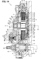
- 14 eine Schnittansicht einer Drehantriebsvorrichtung gemäß einer vierten Ausführungsform;
- 15 eine Abbildung ausgehend von der Richtung eines Pfeils XV von 14 betrachtet; und
- 16 eine Schnittansicht einer Drehantriebsvorrichtung gemäß einer fünften Ausführungsform.
The foregoing and other objects, features and advantages of the present disclosure will become more apparent from the following detailed description made with reference to the accompanying drawings. In the pictures are: - 1 a sectional view of a rotary actuator according to a first embodiment;
- 2 a schematic view of a shift-by-wire system, in which the rotary actuator according to the first embodiment is used;
- 3A a front view of one end of a shaft;
- 3B an illustration from the direction of an arrow IIIB of 3A considered;
- 4 an illustration showing an output shaft and a shaft of the rotary actuator according to the first embodiment viewed from an axial direction;
- 5 a perspective view of the output shaft of the rotary actuator according to the first embodiment;
- 6 an illustration showing a magnet holder of the rotary actuator according to the first embodiment viewed from the axial direction;
- 7 a sectional view taken along a line VII-VII of 6 considered;
- 8th a perspective view of the magnet holder of the rotary actuator according to the first embodiment;
- 9 a sectional perspective view of the magnet holder of the rotary actuator according to the first embodiment;
- 10 an illustration illustrating an output shaft and a shaft of a rotary actuator according to a second embodiment viewed from the axial direction;
- 11 a sectional view of a rotary drive device according to a third embodiment;
- 12 a schematic view of a shift-by-wire system, in which the rotary drive device according to the third embodiment is used;
- 13 an illustration showing a part of the rotary drive device according to the third embodiment, as viewed from the direction of an arrow XIII 11 , represents;
- 14 a sectional view of a rotary drive device according to a fourth embodiment;
- 15 a figure starting from the direction of an arrow XV of 14 considered; and
- 16 a sectional view of a rotary drive device according to a fifth embodiment.
Beschreibung von AusführungsformenDescription of embodiments
Im Folgenden werden Drehstellglieder gemäß einer Vielzahl von Ausführungsformen mit Bezug auf die 1 bis 10 beschrieben. Im Wesentlichen identische Elemente sind in den in den 1 bis 10 dargestellten Ausführungsformen durch die gleichen Bezugszeichen gekennzeichnet und auf eine Beschreibung davon wird verzichtet. Darüber hinaus erzielen im Wesentlichen identische Elemente in den Ausführungsformen die gleichen oder ähnliche Effekte.Hereinafter, rotary actuators according to a plurality of embodiments with reference to 1 to 10 described. Essentially identical elements are in the in the 1 to 10 illustrated embodiments by the same reference numerals and a description thereof is omitted. Moreover, substantially identical elements in the embodiments achieve the same or similar effects.
(Erste Ausführungsform)First Embodiment
Ein in 1 dargestelltes Drehstellglied 1 wird beispielsweise als eine Antriebseinheit eines Shift-by-Wire-Systems verwendet, das eine Schaltung eines Automatikgetriebes eines Fahrzeugs umschaltet bzw. wechselt.An in 1 illustrated rotary actuator 1 For example, it is used as a drive unit of a shift-by-wire system that switches a circuit of an automatic transmission of a vehicle.
Zunächst wird das Shift-by-Wire-System beschrieben. Wie in 2 dargestellt ist, ist ein Shift-by-Wire-System 100 mit dem Drehstellglied 1, einer elektronischen Steuerungseinheit (nachfolgend als die „ECU“ bezeichnet) 2, einer Schaltbereichsumschaltvorrichtung 110 und einer Parkumschaltvorrichtung 120 vorgesehen. Das Drehstellglied 1 dreht eine manuelle Welle 200 der Schaltbereichsumschaltvorrichtung 110 als ein Antriebsziel. Entsprechend wird der Schaltbereich eines Automatikgetriebes 108 umgeschaltet. Die Drehung des Drehstellglieds 1 wird durch die ECU 2 gesteuert. Das Drehstellglied 1 ist beispielsweise an einer Wand 130 der Schaltbereichsumschaltvorrichtung 110 als ein Befestigungsziel befestigt. Das Drehstellglied 1 treibt einen Parkstab 121 der Parkumschaltvorrichtung 120 an, indem die manuelle Welle 200 der Schaltbereichsumschaltvorrichtung 110 rotiert wird. Die manuelle Welle 200 entspricht der „Welle“.First, the shift-by-wire system will be described. As in 2 is shown is a shift-by-wire system 100 with the rotary actuator 1 an electronic control unit (hereinafter referred to as the "ECU") 2 a shift range switching device 110 and a parking switching device 120 intended. The rotary actuator 1 turns a manual shaft 200 the shift range switching device 110 as a drive target. Accordingly, the shift range of an automatic transmission 108 switched. The rotation of the rotary actuator 1 is through the ECU 2 controlled. The rotary actuator 1 is for example on a wall 130 the shift range switching device 110 attached as a mounting target. The rotary actuator 1 drives a parking pole 121 the park switching device 120 on by the manual shaft 200 the shift range switching device 110 is rotated. The manual wave 200 corresponds to the "wave".
Die Schaltbereichsumschaltvorrichtung 110 umfasst die manuelle Welle 200, eine Sperrplatte 102, einen Hydraulikventilkörper 104 und die Wand 130. Die Wand 130 nimmt die manuelle Welle 200, die Sperrplatte 102 und den Hydraulikventilkörper 104 darin auf. Ein Ende der manuellen Welle 200 steht von der Wand 130 über ein Loch 131 (siehe 1), das bei der Wand 130 ausgebildet ist, vor.The shift range switching device 110 includes the manual shaft 200 , a blocking plate 102 , a hydraulic valve body 104 and the wall 130 , The wall 130 takes the manual shaft 200 , the lock plate 102 and the hydraulic valve body 104 in it. An end of the manual shaft 200 stands from the wall 130 over a hole 131 (please refer 1 ), by the wall 130 is formed before.
Das eine Ende der manuellen Welle 200 ist bei einer Ausgangswelle 80 des Drehstellglieds 1 angebracht (nachstehend beschrieben). Die Sperrplatte 102 ist in einer Sektorform ausgebildet, die sich von der manuellen Welle 200 in der radialen Richtung nach außen erstreckt, und rotiert integral mit der manuellen Welle 200. Die Sperrplatte 102 ist mit einem Stift 103 versehen, der parallel zur manuellen Welle 200 vorsteht. The one end of the manual shaft 200 is at an output shaft 80 of the rotary actuator 1 attached (described below). The lock plate 102 is formed in a sector shape different from the manual shaft 200 extends outwardly in the radial direction and rotates integrally with the manual shaft 200 , The lock plate 102 is with a pen 103 provided parallel to the manual shaft 200 protrudes.
Der Stift 103 ist an einem Ende eines manuellen Spulenventils 105 befestigt, das am Hydraulikventilkörper 104 angeordnet ist. Somit bewegt sich das manuelle Spulenventil 105 in einer axialen Richtung durch die Sperrplatte 102, die sich integral mit der manuellen Welle 200 dreht, hin und her. Das manuelle Spulenventil 105 bewegt sich in der axialen Richtung hin und her, um einen Hydraulikzuführdurchlass zu einer hydraulischen Kupplung in dem Automatikgetriebe 108 umzuschalten. Folglich wird ein Eingriffszustand der hydraulischen Kupplung umgeschaltet, was den Schaltbereich des Automatikgetriebes 108 verändert.The pencil 103 is at one end of a manual spool valve 105 attached to the hydraulic valve body 104 is arranged. Thus, the manual spool valve moves 105 in an axial direction through the lock plate 102 that integrates with the manual shaft 200 turns, back and forth. The manual spool valve 105 moves back and forth in the axial direction to a hydraulic supply passage to a hydraulic clutch in the automatic transmission 108 switch. Consequently, an engaged state of the hydraulic clutch is switched, which is the shift range of the automatic transmission 108 changed.
Die Sperrplatte 102 umfasst eine Aussparung 151, eine Aussparung 152, eine Aussparung 153 und eine Aussparung 154 an einem Ende in radialer Richtung. Die Aussparungen 151 bis 154 entsprechen beispielsweise einem P-Bereich, einem R-Bereich, einem N-Bereich und einem D-Bereich, die jeweils dem Schaltbereich des Automatikgetriebes 108 entsprechen. Ein Anschlag 107, der an einer Spitze einer Blattfeder 106 getragen ist, wird in irgendeine der Aussparungen 151 bis 154 der Sperrplatte 102 eingepasst. Entsprechend wird eine Position des manuellen Spulenventils 105 in einer axialen Richtung bestimmt. Zu dieser Zeit wird eine Drehposition der manuellen Welle 200 an einer vorbestimmten Position gehalten. Die Sperrplatte 102, die Blattfeder 106 und der Anschlag 107 bilden einen „Haltemechanismus“, der in der Lage ist, die manuelle Welle 200 zu positionieren, indem die Drehposition der manuellen Welle 200 bei der vorbestimmten Position gehalten wird.The lock plate 102 includes a recess 151 , a recess 152 , a recess 153 and a recess 154 at one end in the radial direction. The recesses 151 to 154 correspond to, for example, a P range, an R range, an N range, and a D range, each corresponding to the shift range of the automatic transmission 108 correspond. An attack 107 standing at a top of a leaf spring 106 is carried into any of the recesses 151 to 154 the locking plate 102 fitted. Accordingly, a position of the manual spool valve becomes 105 determined in an axial direction. At this time, a rotational position of the manual shaft 200 held at a predetermined position. The lock plate 102 , the leaf spring 106 and the stop 107 form a "holding mechanism" that is capable of the manual shaft 200 to position by the rotational position of the manual shaft 200 is held at the predetermined position.
Wenn ein Drehmoment von dem Drehstellglied 1 über die manuelle Welle 200 auf die Sperrplatte 102 aufgebracht wird, bewegt sich der Anschlag 107 hin zu einer anderen benachbarten Aussparung (irgendeine der Aussparungen 151 bis 154). Entsprechend wird die Position des manuellen Spulenventils 105 in der axialen Richtung verändert.When a torque from the rotary actuator 1 over the manual shaft 200 on the lock plate 102 is applied, the stop moves 107 towards another adjacent recess (any of the recesses 151 to 154 ). Accordingly, the position of the manual spool valve becomes 105 changed in the axial direction.
Wenn beispielsweise die manuelle Welle 200 bei einer Ansicht von einem Pfeil Y von 2 im Uhrzeigersinn gedreht wird, drückt der Stift 103 das manuelle Spulenventil 105 über die Sperrplatte 102 in den Hydraulikventilkörper 104, was einen Öldurchlass innerhalb des Hydraulikventilkörpers 104 auf D, N, R und P in dieser Reihenfolge umschaltet. Entsprechend wird der Schaltbereich des Automatikgetriebes 108 in dieser Reihenfolge auf D, N, R und P umgeschaltet.If, for example, the manual shaft 200 in a view from an arrow Y from 2 Turned clockwise, the pin presses 103 the manual spool valve 105 over the locking plate 102 in the hydraulic valve body 104 what an oil passage within the hydraulic valve body 104 switches to D, N, R and P in this order. Accordingly, the shift range of the automatic transmission 108 switched to D, N, R and P in this order.
Wenn die manuelle Welle 200 andererseits entgegen den Uhrzeigersinn gedreht wird, zieht der Stift 103 das manuelle Spulenventil 105 aus dem Hydraulikventilkörper 104 heraus, was den Öldurchlass innerhalb des Hydraulikventilkörpers 104 auf P, R, N und D in dieser Reihenfolge umschaltet. Entsprechend wird der Schaltbereich des Automatikgetriebes 108 auf P, R, N und D in dieser Reihenfolge umgeschaltet.If the manual shaft 200 on the other hand is rotated counterclockwise, pulls the pen 103 the manual spool valve 105 from the hydraulic valve body 104 out what the oil passage inside the hydraulic valve body 104 switched to P, R, N and D in this order. Accordingly, the shift range of the automatic transmission 108 switched to P, R, N and D in this order.
Auf diese Art und Weise entspricht ein Drehwinkel, das heißt, eine vorbestimmte Position in einer Drehrichtung der manuellen Welle 200, die durch das Drehstellglied 1 angetrieben wird, um zu rotieren, jedem Schaltbereich des Automatikgetriebes 108.In this way, a rotation angle, that is, a predetermined position in a rotating direction of the manual shaft 200 passing through the rotary actuator 1 is driven to rotate, each shift range of the automatic transmission 108 ,
Die Parkumschaltvorrichtung 120 umfasst den Parkstab 121, eine Parkstange bzw. Parkklinke 123 und ein Parkzahnrad 126. Der Parkstab 121 ist in einer im Wesentlichen L-förmigen Form ausgebildet. Die Sperrplatte 102 ist mit einem Ende des Parkstabs 121 verbunden. Ein konischer Teil 122 ist am anderen Ende des Parkstabs 121 angeordnet. Der Parkstab 121 wandelt eine Drehbewegung der Sperrplatte 102 in eine lineare Bewegung um, die den konischen Teil 122 in der axialen Richtung hin und her bewegt. Die Parkstange 123 liegt an der Seitenfläche des konischen Teils 122 an. Wenn sich der Parkstab 121 hin und her bewegt, dreht sich somit die Parkstange 123 um eine Welle 124.The parking switching device 120 includes the parking pole 121 , a parking pole or parking pawl 123 and a parking gear 126 , The parking pole 121 is formed in a substantially L-shaped form. The lock plate 102 is with one end of the parking pole 121 connected. A conical part 122 is at the other end of the parking pole 121 arranged. The parking pole 121 converts a rotational movement of the locking plate 102 in a linear motion around the conical part 122 moved back and forth in the axial direction. The park bar 123 lies on the side surface of the conical part 122 on. When the parking pole 121 moved back and forth, thus turning the parking pole 123 around a wave 124 ,
Die Parkstange 123 ist mit einem Vorsprung 125 in der Drehrichtung davon versehen. Wenn der Vorsprung 125 mit den Zähnen des Parkzahnrads 126 ineinander greift, ist die Drehung des Parkzahnrads 126 beschränkt. Entsprechend wird ein Antriebsrad durch eine Antriebswelle oder ein Differentialgetriebe (nicht dargestellt) gesperrt. Andererseits wird, wenn der Vorsprung 125 der Parkstange 123 von den Zähnen des Parkzahnrads 126 gelöst wird, das Parkzahnrad 126 rotierbar und die Sperrung des Antriebsrades wird gelöst.The park bar 123 is with a lead 125 provided in the direction of rotation thereof. If the lead 125 with the teeth of the parking gear 126 meshes with each other, is the rotation of the parking gear 126 limited. Accordingly, a drive wheel is locked by a drive shaft or a differential gear (not shown). On the other hand, if the projection 125 the park bar 123 from the teeth of the parking gear 126 is solved, the parking gear 126 rotatable and the blocking of the drive wheel is released.
Als nächstes wird das Drehstellglied 1 beschrieben.Next, the rotary actuator 1 will be described.
Wie in 1 dargestellt ist, ist das Drehstellglied 1 mit einem Gehäuse 10, einer Eingangswelle 20, einem Motor 3, einem Untersetzungsgetriebe 50 als ein Getriebemechanismus, einem Ausgangszahnrad 60, einer Ausgangswelle 80, einem Magnethalter 90, einer Scheibe 922, einer Feder 94, einem Magneten 35 und einem Winkelsensor 45 versehen.As in 1 is shown, the rotary actuator 1 with a housing 10 , an input shaft 20 a motor 3 , a reduction gear 50 as a gear mechanism, an output gear 60 , an output shaft 80 , a magnet holder 90 , a slice 922 , a spring 94 , a magnet 35 and an angle sensor 45 Provided.
Das Gehäuse 10 umfasst ein vorderes Gehäuse 11, ein hinteres Gehäuse 12 und eine Abdeckung 13. Das vordere Gehäuse 11 ist beispielsweise aus Harz hergestellt. Das hintere Gehäuse 12 ist beispielsweise aus Metall, wie Aluminium, hergestellt. Die Abdeckung 13 ist beispielsweise aus Metall hergestellt und in einer plattenförmigen Gestalt ausgebildet.The housing 10 includes a front housing 11 , a rear housing 12 and a cover 13 , The front housing 11 is made of resin, for example. The rear housing 12 is For example, made of metal, such as aluminum. The cover 13 For example, is made of metal and formed in a plate-like shape.
Jedes Gehäuse des vorderen Gehäuses 11 und des hinteren Gehäuses 12 ist in einer mit einem Boden versehenen Rohrform ausgebildet. Das vordere Gehäuse 11 und das hintere Gehäuse 12 sind mit einem Bolzen 4 fixiert, wobei Öffnungen des vorderen Gehäuses 11 und des hinteren Gehäuses 12 miteinander verbunden sind. Entsprechend ist zwischen dem vorderen Gehäuse 11 und dem hinteren Gehäuse 12 ein Raum 5 ausgebildet. Die Abdeckung 13 bedeckt das hintere Gehäuse 12 auf der dem vorderen Gehäuse 11 entgegengesetzten Seite.Each housing of the front housing 11 and the rear housing 12 is formed in a bottomed tube shape. The front housing 11 and the rear housing 12 are with a bolt 4 fixed, with openings of the front housing 11 and the rear housing 12 connected to each other. Accordingly, between the front housing 11 and the rear housing 12 a room 5 educated. The cover 13 covers the rear housing 12 on the front housing 11 opposite side.
Bei der vorliegenden Ausführungsform ist das Drehstellglied 1 so an der Wand 130 angebracht, dass eine Fläche des vorderen Gehäuses 11 auf der Seite entgegengesetzten zu dem hinteren Gehäuse 12 der Wand 130 der Schaltbereichsumschaltvorrichtung 110 zugewandt ist.In the present embodiment, the rotary actuator 1 on the wall 130 attached to a surface of the front housing 11 on the side opposite to the rear housing 12 the Wall 130 the shift range switching device 110 is facing.
Die Eingangswelle 20 ist beispielsweise aus Metall hergestellt. Die Eingangswelle 20 umfasst einen Endteil 21, ein Teil 22 mit großem Durchmesser, einen exzentrischen Teil 23 und den anderen Endteil 24. Der eine Endteil 21, der Teil 22 mit großem Durchmesser, der exzentrische Teil 23 und der andere Endteil 24 sind integral ausgebildet und in der Richtung einer Achse Ax1 in dieser Reihenfolge nebeneinander angeordnet.The input shaft 20 is made of metal, for example. The input shaft 20 includes an end part 21 , a part 22 with large diameter, an eccentric part 23 and the other end part 24 , The one end part 21 , the part 22 with large diameter, the eccentric part 23 and the other end part 24 are integrally formed and in the direction of an axis Ax1 arranged side by side in this order.
Der eine Endteil 21 ist säulenförmig ausgebildet. Der Teil 22 mit großem Durchmesser ist in einer säulenförmigen Gestalt mit einem größeren Außendurchmesser als dieser des einen Endteils 21 und koaxial (die Achse Ax1) mit dem einen Endteil 21 ausgebildet. Der exzentrische Teil 23 ist in einer säulenförmigen Gestalt mit einem kleineren Außendurchmesser als dieser des Teils 22 mit großem Durchmesser und exzentrisch mit Bezug auf die Achse Ax1, die einer Rotationsmitte der Eingangswelle 20 entspricht, ausgebildet. Das heißt, der exzentrische Teil 23 ist mit Bezug auf den einen Endteil 21 und den Teil 22 mit großem Durchmesser exzentrisch. Der andere Endteil 24 ist in einer säulenförmigen Gestalt mit einem kleineren Außendurchmesser als dieser des exzentrischen Teils 23 und koaxial (die Achse Ax1) mit dem einen Endteil 21 und dem Teil 22 mit großem Durchmesser ausgebildet.The one end part 21 is columnar. The part 22 of large diameter is in a columnar shape having a larger outer diameter than that of the one end portion 21 and coaxial (the axis Ax1 ) with the one end part 21 educated. The eccentric part 23 is in a columnar shape with a smaller outer diameter than that of the part 22 with large diameter and eccentric with respect to the axis Ax1 , which is a center of rotation of the input shaft 20 corresponds, trained. That is, the eccentric part 23 is with respect to the one end part 21 and the part 22 eccentric with large diameter. The other end part 24 is in a columnar shape with a smaller outer diameter than that of the eccentric part 23 and coaxial (the axis Ax1 ) with the one end part 21 and the part 22 formed with a large diameter.
Der andere Endteil 24 der Eingangswelle 20 ist durch ein vorderes Lager 16 rotierbar getragen bzw. gelagert, und der eine Endteil 21 der Eingangswelle 20 ist durch ein hinteres Lager 17 rotierbar gelagert. Bei der vorliegenden Ausführungsform entspricht jedes Lager aus dem vorderen Lager 16 und dem hinteren Lager 17 beispielsweise einem Kugellager.The other end part 24 the input shaft 20 is through a front camp 16 rotatably supported or stored, and the one end part 21 the input shaft 20 is through a rear warehouse 17 rotatably mounted. In the present embodiment, each bearing corresponds to the front bearing 16 and the rear bearing 17 for example, a ball bearing.
Das vordere Lager 16 ist innerhalb des Ausgangszahnrades 60 angeordnet (nachstehend beschrieben). Das Ausgangszahnrad 60 ist durch ein Metalllager 18 rotierbar gelagert, das im Inneren des vorderen Gehäuses 11 angeordnet ist. Das Metalllager 18 ist aus Metall hergestellt und besitzt eine rohrförmige Gestalt. Das heißt, der andere Endteil 24 der Eingangswelle 20 ist durch das Metalllager 18, das Ausgangszahnrad 60 und das vordere Lager 16 rotierbar gelagert, die im vorderen Gehäuse 11 angeordnet sind. Andererseits ist der eine Endteil 21 der Eingangswelle 20 durch das hintere Lager 17, das auf dem Boden des hinteren Gehäuses 12 angeordnet ist, rotierbar gelagert. Auf diese Art und Weise ist die Eingangswelle 20 durch das Gehäuse 10 rotierbar gelagert.The front bearing 16 is inside the output gear 60 arranged (described below). The output gear 60 is through a metal warehouse 18 rotatably mounted inside the front housing 11 is arranged. The metal warehouse 18 is made of metal and has a tubular shape. That is, the other end part 24 the input shaft 20 is through the metal warehouse 18 , the output gear 60 and the front bearing 16 rotatably mounted, in the front housing 11 are arranged. On the other hand, the one end part 21 the input shaft 20 through the rear warehouse 17 that is on the bottom of the rear case 12 is arranged rotatably mounted. In this way, the input shaft 20 through the housing 10 rotatably mounted.
Der Motor 3 ist beispielsweise ein bürstenloser Dreiphasenmotor. Der Motor 3 ist auf der Seite des hinteren Gehäuses 12 in dem Raum 5 angeordnet. Das heißt, der Motor 3 ist im Gehäuse 10 aufgenommen. Der Motor 3 umfasst einen Stator 30, eine Spule 33 und einen Rotor 40.The motor 3 is, for example, a brushless three-phase motor. The motor 3 is on the side of the rear case 12 in the room 5 arranged. That is, the engine 3 is in the case 10 added. The motor 3 includes a stator 30 , a coil 33 and a rotor 40 ,
Der Stator 30 ist in einer im Wesentlichen ringförmigen Gestalt ausgebildet. Der Stator 30 ist drehfest an dem hinteren Gehäuse 12 befestigt, indem dieser in eine Platte 8 eingepresst ist, die aus Metall hergestellt und an dem hinteren Gehäuse 12 fixiert ist.The stator 30 is formed in a substantially annular shape. The stator 30 is rotationally fixed to the rear housing 12 fastened by placing this in a plate 8th is pressed in, made of metal and on the rear housing 12 is fixed.
Der Stator 30 ist beispielsweise aus einem magnetischen Material, wie Eisen, hergestellt. Der Stator 30 umfasst einen Statorkern 31 und Statorzähne 32. Der Statorkern 31 ist in einer ringförmigen Gestalt ausgebildet. Die Statorzähne 32 ragen in der radialen Richtung vom Statorkern 31 nach innen vor. Die Statorzähne 32 sind bei regelmäßigen Abständen in der Umfangsrichtung des Statorkerns 31 ausgebildet.The stator 30 For example, it is made of a magnetic material such as iron. The stator 30 includes a stator core 31 and stator teeth 32 , The stator core 31 is formed in an annular shape. The stator teeth 32 protrude in the radial direction from the stator core 31 inside. The stator teeth 32 are at regular intervals in the circumferential direction of the stator core 31 educated.
Die Spule 33 ist um jeden der Statorzähne 32 gewickelt. Die Spule 33 ist elektrisch mit einer Sammelschiene 70 verbunden. Die Sammelschiene 70 ist auf dem Boden des hinteren Gehäuses 12 angeordnet, wie in 1 dargestellt. Die der Spule 33 zugeführte Leistung bzw. der Strom fließt durch die Sammelschiene 70. Die Sammelschiene 70 umfasst einen Anschluss bzw. eine Klemme 71, die mit der Spule 33 verbunden ist. Die Spule 33 ist elektrisch mit der Klemme 71 verbunden. Strom wird der Klemme 71 gemäß einem von der ECU 2 ausgegebenen Antriebssignal zugeführt.The sink 33 is around each of the stator teeth 32 wound. The sink 33 is electric with a busbar 70 connected. The busbar 70 is on the bottom of the rear case 12 arranged as in 1 shown. The coil 33 supplied power or the current flows through the busbar 70 , The busbar 70 includes a terminal or a terminal 71 that with the coil 33 connected is. The sink 33 is electrical with the clamp 71 connected. Electricity is the pinch 71 according to one of the ECU 2 supplied drive signal supplied.
Der Rotor 40 ist in der radialen Richtung im Inneren des Stators 30 angeordnet. Der Rotor 40 umfasst einen Rotorkern 41 und einen Magneten 42. Der Rotorkern 41 wird beispielsweise durch Laminieren einer Mehrzahl von dünnen Platten, die aus einem magnetischen Material, wie Eisen, hergestellt sind, in einer Plattendickenrichtung gebildet. Der Rotorkern 41 ist in einer ringförmigen Gestalt ausgebildet und bei dem Teil 22 mit großem Durchmesser der Eingangswelle 20 eingepresst und fixiert. Der Magnet 42 ist ringförmig ausgebildet und in radialer Richtung außerhalb des Rotorkerns 41 angeordnet. Der Magnet 42 ist in einer solchen Art und Weise polarisiert, dass der N-Pol und der S-Pol in der Umfangsrichtung abwechselnd angeordnet sind. Der Rotor 40 ist relativ zu dem Gehäuse 10 und dem Stator 30 zusammen mit der Eingangswelle 20 durch den bei der Eingangswelle 20 eingepressten und fixierten Rotorkern 41 rotierbar.The rotor 40 is in the radial direction inside the stator 30 arranged. The rotor 40 includes a rotor core 41 and a magnet 42 , The rotor core 41 is formed in a plate thickness direction, for example, by laminating a plurality of thin plates made of a magnetic material such as iron. The rotor core 41 is formed in an annular shape and in the part 22 with large diameter of the input shaft 20 pressed in and fixed. The magnet 42 is annular and in the radial direction outside of the rotor core 41 arranged. The magnet 42 is polarized in such a manner that the N pole and the S pole are alternately arranged in the circumferential direction. The rotor 40 is relative to the housing 10 and the stator 30 together with the input shaft 20 through the at the input shaft 20 Pressed and fixed rotor core 41 rotatable.
Wenn die Spule 33 mit Strom versorgt wird, wird in den Statorzähnen 32, um welche die Spulen 33 gewickelt sind, eine Magnetkraft erzeugt. Entsprechend wird der Magnetpol des Magneten 42 des Rotors 40 von dem entsprechenden der Statorzähne 32 angezogen. Die Spulen 33 bilden drei Phasen, beispielsweise eine U-Phase, eine V-Phase und eine W-Phase. Wenn die ECU 2 die Bestromung bzw. Erregung auf die U-Phase, die V-Phase und die W-Phase in dieser Reihenfolge umschaltet, rotiert der Rotor 40 beispielsweise hin zu einer Seite in der Umfangsrichtung. Wenn die ECU 2 dagegen die Erregung auf die W-Phase, die V-Phase und die U-Phase in dieser Reihenfolge umschaltet, rotiert der Rotor 40 hin zu der anderen Seite in der Umfangsrichtung. Auf diese Art und Weise ist es möglich, den Rotor 40 in irgendeine Richtung zu drehen, indem die in den Statorzähnen 32 erzeugte Magnetkraft durch Umschalten der Erregung jeder der Spulen 33 gesteuert wird.If the coil 33 is powered in the stator teeth 32 around which the coils 33 are wound, generates a magnetic force. Accordingly, the magnetic pole of the magnet 42 of the rotor 40 from the corresponding one of the stator teeth 32 dressed. The spools 33 form three phases, for example a U-phase, a V-phase and a W-phase. If the ECU 2 the energization switches to the U phase, the V phase and the W phase in this order, the rotor rotates 40 for example, towards a side in the circumferential direction. If the ECU 2 whereas the excitation switches to the W-phase, the V-phase and the U-phase in this order, the rotor rotates 40 towards the other side in the circumferential direction. In this way it is possible to use the rotor 40 to turn in any direction by the in the stator teeth 32 generated magnetic force by switching the excitation of each of the coils 33 is controlled.
Bei der vorliegenden Ausführungsform wird durch die Magnetkraft zwischen dem Magneten 42 und den Statorzähnen 32 ein relativ großes Rastmoment erzeugt. Wenn also der Motor 3 nicht bestromt wird, kann der Rotor 40 bei einer vorbestimmten Drehposition arretiert sein.In the present embodiment, the magnetic force between the magnet 42 and the stator teeth 32 generates a relatively large cogging torque. So if the engine 3 is not energized, the rotor can 40 be locked at a predetermined rotational position.
Bei der vorliegenden Ausführungsform ist ein Drehgeber 72 zwischen dem Boden des hinteren Gehäuses 12 und dem Rotorkern 41 angeordnet. Der Drehgeber 72 umfasst einen Magneten 73 und eine Hall-IC 75.In the present embodiment, a rotary encoder 72 between the bottom of the rear housing 12 and the rotor core 41 arranged. The encoder 72 includes a magnet 73 and a hall IC 75 ,
Der Magnet 73 entspricht einem mehrpoligen Magneten, der ringförmig ausgebildet und so polarisiert ist, dass der N-Pol und der S-Pol in der Umfangsrichtung abwechselnd angeordnet sind. Der Magnet 73 ist koaxial zum Rotorkern 41 und an einem Ende des Rotorkerns 41 auf der Seite des hinteren Gehäuses 12 angeordnet. Zwischen dem hinteren Gehäuse 12 und der Abdeckung 13 ist ein Substrat 74 angeordnet. Die Hall-IC 75 ist auf dem Substrat 74 montiert, um dem Magneten 73 zugewandt zu sein.The magnet 73 corresponds to a multi-pole magnet which is annular and polarized so that the N pole and the S pole are alternately arranged in the circumferential direction. The magnet 73 is coaxial with the rotor core 41 and at one end of the rotor core 41 on the side of the rear housing 12 arranged. Between the rear housing 12 and the cover 13 is a substrate 74 arranged. The Hall IC 75 is on the substrate 74 mounted to the magnet 73 to be facing.
Die Hall-IC 75 umfasst ein Hall-Element und eine Signalumwandlungsschaltung. Das Hall-Element ist ein magnetoelektrisches Umwandlungselement, das einen Hall-Effekt nutzt und ein elektrisches Signal proportional zu der Dichte des vom Magneten 73 erzeugten magnetischen Flusses ausgibt. Die Signalumwandlungsschaltung wandelt ein Ausgangssignal des Hall-Elements in ein digitales Signal um. Die Hall-IC 75 gibt ein Impulssignal synchron zur Drehung des Rotorkerns 41 an die ECU 2 aus. Die ECU 2 ist in der Lage, den Drehwinkel und die Drehrichtung des Rotorkerns 41 auf Basis des Impulssignals von der Hall-IC 75 zu erfassen.The Hall IC 75 includes a Hall element and a signal conversion circuit. The Hall element is a magnetoelectric conversion element that uses a Hall effect and an electrical signal proportional to the density of the magnet 73 generates generated magnetic flux. The signal conversion circuit converts an output signal of the Hall element into a digital signal. The Hall IC 75 gives a pulse signal in synchronization with the rotation of the rotor core 41 to the ECU 2 out. The ECU 2 is capable of the rotation angle and the direction of rotation of the rotor core 41 based on the pulse signal from the Hall IC 75 capture.
Das Untersetzungsgetriebe bzw. die Untersetzung 50 umfasst ein Hohlrad 51 und ein Sonnenrad 52.The reduction gear or the reduction 50 includes a ring gear 51 and a sun wheel 52 ,
Das Hohlrad 51 ist beispielsweise aus Metall, wie Eisen, hergestellt und ringförmig geformt. Das Hohlrad 51 ist zusammen mit der Platte 8 nicht rotierbar an dem hinteren Gehäuse 12 fixiert. Das Hohlrad 51 ist koaxial (die Achse Ax1) mit der Eingangswelle 20 am Gehäuse 10 fixiert. Das Hohlrad 51 umfasst innere Zähne bzw. eine Innenverzahnung 53, die am inneren Rand davon ausgebildet sind.The ring gear 51 For example, is made of metal, such as iron, and shaped annular. The ring gear 51 is together with the plate 8th not rotatable on the rear housing 12 fixed. The ring gear 51 is coaxial (the axis Ax1 ) with the input shaft 20 on the housing 10 fixed. The ring gear 51 includes internal teeth or an internal toothing 53 formed on the inner edge thereof.
Das Sonnenrad 52 ist beispielsweise aus Metall, wie Eisen, hergestellt und in einer im Wesentlichen scheibenförmigen Gestalt ausgebildet. Das Sonnenrad 52 umfasst einen Vorsprung 54 mit einer säulenförmigen Gestalt. Der Vorsprung 54 steht in einer Plattendickenrichtung von einer Position, die von der Mitte einer Fläche des Sonnenrads 52 in der radialen Richtung nach außen um einen vorbestimmten Abstand entfernt liegt, vor. Eine Mehrzahl von Vorsprüngen 54 sind bei regelmäßigen Abständen in der Umfangsrichtung des Sonnenrads 52 ausgebildet. Das Sonnenrad 52 umfasst äußere Zähne bzw. eine Außenverzahnung 55, die am äußeren Rand des Sonnenrads 52 ausgebildet sind, um mit den inneren Zähnen bzw. der Innenverzahnung 53 des Hohlrads 51 ineinander zu greifen. Das Sonnenrad 52 ist mit Bezug auf die Eingangswelle 20 über ein mittleres Lager 19, das am Außenumfang des exzentrischen Teils 23 der Eingangswelle 20 angeordnet ist, relativ rotierbar und exzentrisch angeordnet. Entsprechend läuft beim Drehen der Eingangswelle 20 das Sonnenrad 52 um, während dieses um dessen eigene Achse innerhalb des Hohlrads 51 rotiert, wobei die äußeren Zähne 55 mit den inneren Zähnen 53 des Hohlrades 51 in Eingriff stehen. Das mittlere Lager 19 ist beispielsweise ein Kugellager, wie das vordere Lager 16 und das hintere Lager 17.The sun wheel 52 is for example made of metal, such as iron, and formed in a substantially disc-shaped shape. The sun wheel 52 includes a projection 54 with a columnar shape. The lead 54 is in a plate thickness direction from a position that is from the center of a surface of the sun gear 52 in the radial direction outward by a predetermined distance away, before. A plurality of protrusions 54 are at regular intervals in the circumferential direction of the sun gear 52 educated. The sun wheel 52 includes outer teeth or external teeth 55 at the outer edge of the sun gear 52 are formed to with the inner teeth or the internal toothing 53 of the ring gear 51 to interlock. The sun wheel 52 is with respect to the input shaft 20 over a middle camp 19 on the outer circumference of the eccentric part 23 the input shaft 20 is arranged, relatively rotatable and arranged eccentrically. Accordingly, when rotating the input shaft runs 20 the sun wheel 52 while this around its own axis within the ring gear 51 rotates, with the outer teeth 55 with the inner teeth 53 of the ring gear 51 engage. The middle camp 19 is for example a ball bearing, as the front bearing 16 and the rear bearing 17 ,
Das Ausgangszahnrad 60 ist beispielsweise aus Metall hergestellt. Das Ausgangszahnrad 60 umfasst einen rohrförmigen Ausgabeteil 61 mit einer im Wesentlichen zylindrischen Gestalt und einen scheibenförmigen Teil 62 mit einer im Wesentlichen scheibenförmigen Gestalt. Der rohrförmige Ausgabeteil 61 ist durch das Gehäuse 10 über das Metalllager 18, das innerhalb des vorderen Gehäuses 11 angeordnet ist, rotierbar gelagert. Der rohrförmige Ausgabeteil 61 ist koaxial zu dem Teil 22 mit großem Durchmesser der Eingangswelle 20. Das vordere Lager 16 ist innerhalb des rohrförmigen Ausgabeteils 61 angeordnet. Entsprechend trägt der rohrförmige Ausgabeteil 61 den anderen Endteil 24 der Eingangswelle 20 über das Metalllager 18 und das vordere Lager 16 rotierbar.The output gear 60 is made of metal, for example. The output gear 60 comprises a tubular dispensing part 61 with a substantially cylindrical shape and a disk-shaped part 62 with a substantially disk-shaped shape. The tubular output part 61 is through the case 10 over the metal bearing 18 that inside the front housing 11 is arranged rotatably mounted. The tubular output part 61 is coaxial with the part 22 with large diameter of the input shaft 20 , The front bearing 16 is inside the tubular dispensing part 61 arranged. Accordingly, the tubular output part carries 61 the other end part 24 the input shaft 20 over the metal bearing 18 and the front bearing 16 rotatable.
Der scheibenförmige Teil 62 ist in einer im Wesentlichen scheibenförmigen Gestalt ausgebildet, die sich in der radialen Richtung von einem Ende des rohrförmigen Ausgabeteils 61 auf der Seite des Sonnenrads 52 in dem Raum 5 nach außen erstreckt. Bei dem scheibenförmigen Teil 62 ist ein Loch 63 ausgebildet. Der Vorsprung 54 des Sonnenrades 52 ist in das Loch 63 einsetzbar. Das Loch 63 durchdringt den scheibenförmigen Teil 62 in der Plattendickenrichtung. Bei der vorliegenden Ausführungsform sind in der Umfangsrichtung des scheibenförmigen Teils 62 entsprechend den Vorsprüngen 54 eine Mehrzahl von Löchern 63 ausgebildet.The disc-shaped part 62 is formed in a substantially disc-shaped shape extending in the radial direction from one end of the tubular dispensing part 61 on the side of the sun gear 52 in the room 5 extends to the outside. In the disk-shaped part 62 is a hole 63 educated. The lead 54 of the sun wheel 52 is in the hole 63 used. The hole 63 penetrates the disk-shaped part 62 in the plate thickness direction. In the present embodiment, in the circumferential direction of the disc-shaped member 62 according to the tabs 54 a plurality of holes 63 educated.
Am Außenrand des scheibenförmigen Teils 62 sind über den gesamten Bereich in der Umfangsrichtung äußere Zähne 64 ausgebildet.At the outer edge of the disc-shaped part 62 are outer teeth over the entire area in the circumferential direction 64 educated.
Bei der vorstehenden Konfiguration wird, wenn das Sonnenrad 52 umläuft, während dieses um eine eigene Achse innerhalb des Hohlrads 51 rotiert, durch Außenwände der Vorsprünge 54 in der Umfangsrichtung des scheibenförmigen Teils 62 auf Innenwände der Löcher 63 des scheibenförmigen Teils 62 des Ausgangszahnrades 60 gedrückt. Entsprechend wird eine Rotationskomponente des Sonnenrades 52 auf das Ausgangszahnrad 60 übertragen. Eine Geschwindigkeit der Rotation des Sonnenrades 52 ist niedriger als eine Drehzahl der Eingangswelle 20. Somit wird eine von dem Motor 3 ausgegebene Drehung verzögert und von dem Ausgangszahnrad 60 ausgegeben. Auf diese Weise dienen das Hohlrad 51 und das Sonnenrad 52 als das „Untersetzungsgetriebe“.In the above configuration, when the sun gear 52 revolves while this around its own axis within the ring gear 51 rotated, through outer walls of the projections 54 in the circumferential direction of the disc-shaped part 62 on inner walls of the holes 63 of the disc-shaped part 62 of the output gear 60 pressed. Accordingly, a rotational component of the sun gear becomes 52 on the output gear 60 transfer. A speed of rotation of the sun gear 52 is lower than a rotational speed of the input shaft 20 , Thus, one of the engine 3 output rotation delayed and from the output gear 60 output. In this way serve the ring gear 51 and the sun wheel 52 as the "reduction gearbox".
Die Ausgangswelle 80 umfasst einen rohrförmigen Wellenteil 81, einen Zahnradteil 82 und ein Wellenloch 83.The output shaft 80 comprises a tubular shaft part 81 , a gear part 82 and a shaft hole 83 ,
Der rohrförmige Wellenteil 81 und der Zahnradteil 82 sind beispielsweise aus Metall hergestellt. Der rohrförmige Wellenteil 81 ist beispielsweise in einer mit einem Boden versehenen Rohrform ausgebildet. Der Zahnradteil 82 ist integral mit dem rohrförmigen Wellenteil 81 ausgebildet. Der Zahnradteil 82 erstreckt sich in der radialen Richtung in einer im Wesentlichen sektoralen Form von einer Außenumfangswand eines Endes des rohrförmigen Wellenteils 81 auf der dem Boden des rohrförmigen Wellenteils 81 entgegengesetzten Seite nach außen. Äußere Zähne 84 sind an dem äußeren Rand des Getriebeteils 82 auf der dem rohrförmigen Wellenteil 81 entgegengesetzten Seite ausgebildet.The tubular shaft part 81 and the gear part 82 are made of metal, for example. The tubular shaft part 81 is formed, for example, in a bottomed tube shape. The gear part 82 is integral with the tubular shaft part 81 educated. The gear part 82 extends in the radial direction in a substantially sectoral shape from an outer peripheral wall of one end of the tubular shaft member 81 on the bottom of the tubular shaft part 81 opposite side to the outside. Outer teeth 84 are on the outer edge of the transmission part 82 on the tubular shaft part 81 formed opposite side.
Die Ausgangswelle 80 ist in dem Raum 5 zwischen dem vorderen Gehäuse 11 und dem hinteren Gehäuse 12 so angeordnet, dass die äußeren Zähne 84 mit den äußeren Zähnen 64 des Ausgangszahnrads 60 ineinander greifen. Die Ausgangswelle 80 ist so angeordnet, dass eine Achse Ax2 des rohrförmigen Wellenteils 81 im Wesentlichen parallel zu der Achse Ax1 der Eingangswelle 20 verläuft.The output shaft 80 is in the room 5 between the front housing 11 and the rear housing 12 arranged so that the outer teeth 84 with the outer teeth 64 of the output gear 60 mesh. The output shaft 80 is arranged so that an axis Ax2 of the tubular shaft part 81 essentially parallel to the axis Ax1 the input shaft 20 runs.
Wenn der Motor 3 zum Drehen des Ausgangszahnrades 60 angetrieben wird, um sich zu drehen, rotiert die Ausgangswelle 80 um die Achse Ax2 des rohrförmigen Wellenteils 81. Das heißt, die Ausgangswelle 80 rotiert durch das von dem Motor 3 abgegebene Drehmoment.If the engine 3 for turning the output gear 60 is driven to rotate, the output shaft rotates 80 around the axis Ax2 of the tubular shaft part 81 , That is, the output shaft 80 rotated by that of the engine 3 delivered torque.
Die Ausgangswelle 80 ist so angeordnet, dass der rohrförmige Wellenteil 81 innerhalb eines Metalllagers 87 angeordnet ist, das am vorderen Gehäuse 11 angeordnet ist und eine Rohrform aufweist. Entsprechend ist die Ausgangswelle 80 durch das vordere Gehäuse 11 über das Metalllager 87 rotierbar gelagert.The output shaft 80 is arranged so that the tubular shaft part 81 inside a metal warehouse 87 is arranged on the front housing 11 is arranged and has a tubular shape. Accordingly, the output shaft 80 through the front housing 11 over the metal bearing 87 rotatably mounted.
Das Wellenloch 83 durchdringt den Boden des rohrförmigen Wellenteils 81 in der axialen Richtung. Das heißt, das Wellenloch 83 durchdringt den rohrförmigen Wellenteil 81 der Ausgangswelle 80 in Richtung der Achse Ax2. Die Gestalt des Wellenlochs 83 wird im Folgenden beschrieben.The shaft hole 83 penetrates the bottom of the tubular shaft part 81 in the axial direction. That is, the shaft hole 83 penetrates the tubular shaft part 81 the output shaft 80 in the direction of the axis Ax2 , The shape of the shaft hole 83 is described below.
Wie in 1 dargestellt ist, sind die Ausgangswelle 80 und die manuelle Welle 200 miteinander gekoppelt, indem ein Ende der manuellen Welle 200 des Shift-by-Wire-Systems 100 bei dem Wellenloch 83 der Ausgangswelle 80 eingepasst bzw. eingefügt ist. Entsprechend gibt die Ausgangswelle 80 ein Drehmoment des Motors 3 auf die manuelle Welle 200 ab, wenn die Drehung der Eingangswelle 20 über das Untersetzungsgetriebe 50 und das Ausgangszahnrad 60 auf die Ausgangswelle 80 übertragen wird.As in 1 is shown, are the output shaft 80 and the manual shaft 200 coupled together by one end of the manual shaft 200 of the shift-by-wire system 100 at the shaft hole 83 the output shaft 80 is fitted or inserted. Accordingly, the output shaft 80 a torque of the engine 3 on the manual shaft 200 off when the rotation of the input shaft 20 over the reduction gear 50 and the output gear 60 on the output shaft 80 is transmitted.
Wie in den 3A und 3B dargestellt ist, umfasst die manuelle Welle 200 bei der vorliegenden Ausführungsform einen ersten Befestigungsteil 201, einen zweiten Befestigungsteil 202 und einen kegelförmige Teil 203.As in the 3A and 3B is shown, includes the manual shaft 200 in the present embodiment, a first attachment part 201 , a second fastening part 202 and a cone-shaped part 203 ,
Der erste Befestigungsteil 201 ist auf einer Endseite der manuellen Welle 200 ausgebildet. Der zweite Befestigungsteil 202 ist auf der anderen Endseite der manuellen Welle 200 mit Bezug auf den ersten Befestigungsteil 201 ausgebildet. Der kegelförmige Teil 203 ist bei dem ersten Befestigungsteil 201 auf der Seite entgegengesetzt zu dem zweiten Befestigungsteil 202 ausgebildet. Der kegelförmige Teil 203 ist in einer konischen Gestalt derart ausgebildet, dass sich der kegelförmige Teil 203 einer Achse Ax3 der manuellen Welle 200 von der anderen Endseite der manuellen Welle 200 hin zu der einen Endseite davon annähert.The first fastening part 201 is on one end side of the manual shaft 200 educated. The second fastening part 202 is on the other end side of the manual shaft 200 with respect to the first attachment part 201 educated. The conical part 203 is at the first attachment part 201 on the side opposite to the second fastening part 202 educated. The conical part 203 is formed in a conical shape such that the conical portion 203 an axis Ax 3 the manual shaft 200 from the other end side of the manual shaft 200 towards the one end side approximates.
Ein erster gekrümmter Teil 211 und ein erster ebener Teil 221 sind bei dem ersten Befestigungsteil 201 ausgebildet. Der erste gekrümmte Teil 211 ist entsprechend einem Teil einer virtuellen zylindrischen Ebene, die bei der Achse Ax3 zentriert ist, ausgebildet. Der Durchmesser der virtuellen zylindrischen Ebene ist kleiner als der Durchmesser der manuellen Welle 200.A first curved part 211 and a first level part 221 are at the first attachment part 201 educated. The first curved part 211 is corresponding to a part of a virtual cylindrical plane that is at the axis Ax 3 centered, trained. The diameter of the virtual cylindrical plane is smaller than the diameter of the manual shaft 200 ,
Zwei erste gekrümmte Teile 211 sind bei dem ersten Befestigungsteil 201 mit der dazwischen eingefügten Achse Ax3 ausgebildet. Zwei erste ebene Teile 221 sind auf dem ersten Befestigungsteil 201 mit der dazwischen eingefügten Achse Ax3 zwischen den beiden ersten gekrümmten Teilen 211 ausgebildet. Die beiden ersten ebenen Teile 221 sind jeweils in einer planaren bzw. ebenen Gestalt und parallel zueinander ausgebildet. Auf diese Art und Weise ist das erste Befestigungsteil 201 in einer sogenannten Doppelflächengestalt ausgebildet. Wie in 3A dargestellt ist, ist der Abstand zwischen den beiden ersten ebenen Teilen 221 kleiner als der Durchmesser der manuellen Welle 200.Two first curved parts 211 are at the first attachment part 201 with the intervening axis Ax 3 educated. Two first level parts 221 are on the first attachment part 201 with the intervening axis Ax 3 between the first two curved parts 211 educated. The first two flat parts 221 are each formed in a planar shape and parallel to each other. In this way, the first attachment part 201 formed in a so-called Doppelflächengestalt. As in 3A is shown, the distance between the two first planar parts 221 smaller than the diameter of the manual shaft 200 ,
Ein zweiter gekrümmter Teil 212 und ein zweiter ebener Teil 222 sind auf dem zweiten Befestigungsteil 202 ausgebildet. Der zweite gekrümmte Teil 212 ist entsprechend einem Teil der virtuellen zylindrischen Ebene ausgebildet, die bei der Achse Ax3 zentriert ist. Der Durchmesser der virtuellen zylindrischen Ebene ist kleiner als der Durchmesser der manuellen Welle 200.A second curved part 212 and a second planar part 222 are on the second attachment part 202 educated. The second curved part 212 is formed according to a part of the virtual cylindrical plane, which is at the axis Ax 3 is centered. The diameter of the virtual cylindrical plane is smaller than the diameter of the manual shaft 200 ,
Zwei zweite gekrümmte Teile 212 sind auf dem zweiten Befestigungsteil 202 mit der dazwischen liegenden Achse Ax3 ausgebildet. Zwei zweite ebene Teile 222 sind auf dem zweiten Befestigungsteil 202 mit der dazwischen eingefügten Achse Ax3 zwischen den beiden zweiten gekrümmten Teilen 212 ausgebildet. Die beiden zweiten ebenen Teile 222 sind jeweils in einer ebenen Gestalt und parallel zueinander ausgebildet. Auf diese Art und Weise ist das zweite Befestigungsteil 202 in einer sogenannten Doppelflächengestalt ausgebildet. Wie in 3A dargestellt, ist der Abstand zwischen den beiden zweiten ebenen Teilen 222 kleiner als der Durchmesser der manuellen Welle 200 und im Wesentlichen gleich dem Abstand zwischen den beiden ersten ebenen Teilen 221.Two second curved parts 212 are on the second attachment part 202 with the intermediate axis Ax 3 educated. Two second level parts 222 are on the second attachment part 202 with the intervening axis Ax 3 between the two second curved parts 212 educated. The two second flat parts 222 are each formed in a planar shape and parallel to each other. In this way, the second attachment part 202 formed in a so-called Doppelflächengestalt. As in 3A is shown, the distance between the two second planar parts 222 smaller than the diameter of the manual shaft 200 and substantially equal to the distance between the first two planar parts 221 ,
Wie in den 1 und 4 dargestellt, ist die manuelle Welle 200 bei der vorliegenden Ausführungsform mit der Ausgangswelle 80 so zusammengepasst, dass sich der zweite Befestigungsteil 202 innerhalb des Wellenlochs 83 der Ausgangswelle 80 befindet. Wie in 4 dargestellt, ist der zweite Befestigungsteil 202 der manuellen Welle 200 so ausgebildet, dass ein Abschnitt senkrecht zu der Achse Ax3 bei den zweiten gekrümmten Teilen 212 eine gekrümmte Gestalt und bei den zweiten ebenen Teilen 222 eine lineare Gestalt aufweist.As in the 1 and 4 shown is the manual shaft 200 in the present embodiment, with the output shaft 80 Matched so that the second attachment part 202 inside the shaft hole 83 the output shaft 80 located. As in 4 shown, is the second fastening part 202 the manual shaft 200 designed so that a section perpendicular to the axis Ax 3 at the second curved parts 212 a curved shape and at the second planar parts 222 has a linear shape.
Wie in 4 dargestellt, umfasst das Wellenloch 83 der Ausgangswelle 80 einen gekrümmten Wellenlochteil 831 und einen ebenen Wellenlochteil 832. Der gekrümmte Wellenlochteil 831 ist gemäß einem Teil einer virtuellen zylindrischen Ebene ausgebildet, die bei der Achse Ax2 des rohrförmigen Wellenteils 81 zentriert ist. Bei dem Wellenloch 83 sind zwei gekrümmte Wellenlochteile 831 mit der dazwischen eingefügten Achse Ax2 ausgebildet. Bei dem Wellenloch 83 sind zwei ebene Wellenlochteile 832 mit der dazwischen eingefügten Achse Ax2 zwischen den gekrümmten Wellenlochteilen 831 ausgebildet. Die beiden ebenen Wellenlochteile 832 sind jeweils in einer ebener Gestalt und parallel zueinander ausgebildet. Auf diese Art und Weise ist das Wellenloch 83 in einer sogenannten Doppelflächengestalt ausgebildet, die der Gestalt des zweiten Befestigungsteils 202 entspricht.As in 4 illustrated, includes the shaft hole 83 the output shaft 80 a curved shaft hole part 831 and a plane shaft hole part 832 , The curved shaft hole part 831 is formed according to a part of a virtual cylindrical plane which is at the axis Ax2 of the tubular shaft part 81 is centered. At the shaft hole 83 are two curved shaft pieces 831 with the intervening axis Ax2 educated. At the shaft hole 83 are two level shaft pieces 832 with the intervening axis Ax2 between the curved shaft hole parts 831 educated. The two flat shaft pieces 832 are each formed in a planar shape and parallel to each other. In this way is the shaft hole 83 formed in a so-called double-surface shape, the shape of the second fastening part 202 equivalent.
Wie in 4 dargestellt, ist der Abstand zwischen den beiden gekrümmten Wellenlochteilen 831 der Ausgangswelle 80 etwas größer eingestellt als der Abstand zwischen den beiden zweiten gekrümmten Teilen 212 der manuellen Welle 200. Andererseits ist der Abstand zwischen den beiden ebenen Wellenlochteilen 832 der Ausgangswelle 80 größer eingestellt als der Abstand zwischen den beiden zweiten ebenen Teilen 222 der manuellen Welle 200. Daher ist die manuelle Welle 200 relativ zu der Ausgangswelle 80 im Inneren des Wellenlochs 83 rotierbar. Wenn sich die manuelle Welle 200 relativ zu der Ausgangswelle 80 innerhalb des Wellenlochs 83 dreht, sind die gekrümmten Wellenlochteile 831 und die zweiten gekrümmten Teile 212 entsprechend verschiebbar. Ferner können die zweiten ebenen Teile 222 der manuellen Welle 200 zu dieser Zeit nur an Enden auf der Seite des zweiten gekrümmten Teils 212 mit den ebenen Wellenlochteilen 832 des Wellenlochs 83 in Kontakt kommen. Wenn die zweiten gekrümmten Teile 212 mit den ebenen Wellenlochteilen 832 in Kontakt kommen, ist die relative Drehung zwischen der Ausgangswelle 80 und der manuellen Welle 200 beschränkt.As in 4 is the distance between the two curved shaft hole parts 831 the output shaft 80 set slightly larger than the distance between the two second curved parts 212 the manual shaft 200 , On the other hand, the distance between the two planar shaft hole parts 832 the output shaft 80 set larger than the distance between the two second planar parts 222 the manual shaft 200 , Therefore, the manual shaft 200 relative to the output shaft 80 inside the shaft hole 83 rotatable. When the manual shaft 200 relative to the output shaft 80 inside the shaft hole 83 Turns are the curved shaft parts 831 and the second curved parts 212 correspondingly movable. Furthermore, the second planar parts 222 the manual shaft 200 at this time only at ends on the side of the second curved part 212 with the plane shaft hole parts 832 the shaft hole 83 get in touch. If the second curved parts 212 with the plane shaft hole parts 832 come into contact, is the relative rotation between the output shaft 80 and the manual shaft 200 limited.
Auf diese Weise ist bei der vorliegenden Ausführungsform zwischen der manuellen Welle 200 und der Ausgangswelle 80 ein vorbestimmter Spielbetrag θ0 eingestellt, der gleich oder größer als ein erster vorbestimmter Wert ist. Der erste vorbestimmte Wert ist größer als null. Das heißt, die manuelle Welle 200 ist gegenüber der Ausgangswelle 80 innerhalb des Wellenlochs 83 in einem Winkelbereich des Spiels θ0 rotierbar (siehe 4).In this way, in the present embodiment, between the manual shaft 200 and the output shaft 80 a predetermined amount of play θ0 set equal to or greater than a first one is predetermined value. The first predetermined value is greater than zero. That is, the manual shaft 200 is opposite the output shaft 80 inside the shaft hole 83 in an angular range of the game θ0 rotatable (see 4 ).
Wie in den 1 und 5 dargestellt, ist an einer Endfläche des rohrförmigen Wellenteils 81 auf der dem Boden des rohrförmigen Wellenteils 81 entgegengesetzten Seite ein Drehbegrenzungsloch 85 ausgebildet. Das Drehbegrenzungsloch 85 ist ausgehend von der Endfläche auf der Seite entgegengesetzt zu dem Boden des rohrförmigen Wellenteils 81 hin zu dem Boden vertieft.As in the 1 and 5 is shown at an end face of the tubular shaft part 81 on the bottom of the tubular shaft part 81 opposite side of a rotation limiting hole 85 educated. The rotation limit hole 85 is from the end face on the side opposite to the bottom of the tubular shaft part 81 deepened to the ground.
Wie in den 1 und 6 bis 9 dargestellt, ist der Magnethalter 90 getrennt von der Ausgangswelle 80 ausgebildet. Der Magnethalter 90 umfasst einen ersten rohrförmigen Halterteil 91, einen zweiten rohrförmigen Halterteil 92, einen Haltererstreckungsteil 921, ein Halterloch 93, einen Schlitz 95 und einen kegelförmigen Teil 96.As in the 1 and 6 to 9 shown is the magnet holder 90 separated from the output shaft 80 educated. The magnet holder 90 includes a first tubular holder part 91 , a second tubular holder part 92 , a holder extension part 921 , a holder hole 93 a slot 95 and a cone-shaped part 96 ,
Der erste rohrförmige Halterteil 91 und der zweite rohrförmige Halterteil 92 sind beispielsweise aus Harz hergestellt. Das heißt, der Magnethalter 90 ist aus einem Material mit einem Elastizitätsmodul innerhalb eines vorbestimmten Bereichs hergestellt, der beispielsweise niedriger als typisches Metall und höher als typischer Gummi ist.The first tubular holder part 91 and the second tubular holder part 92 are made of resin, for example. That is, the magnet holder 90 is made of a material having a modulus of elasticity within a predetermined range, for example, lower than typical metal and higher than typical rubber.
Das erste rohrförmige Halterteil 91 ist beispielsweise in einer im Wesentlichen zylindrischen Gestalt ausgebildet. Der zweite rohrförmige Halterteil 92 ist beispielsweise in einer im Wesentlichen mit einem Boden versehenen, zylindrischen Gestalt ausgebildet. Der erste rohrförmige Halterteil 91 ist integral mit dem zweiten rohrförmigen Halterteil 92 ausgebildet. Der erste rohrförmige Halterteil 91 erstreckt sich von dem Boden des zweiten rohrförmigen Halterteils 92 hin zu der Seite entgegengesetzt zu dem rohrförmigen Teil des zweiten rohrförmigen Halterteils 92. Der erste rohrförmige Halterteil 91 ist koaxial (Ax4) mit dem zweiten rohrförmige Halterteil 92.The first tubular holder part 91 is formed, for example, in a substantially cylindrical shape. The second tubular holder part 92 is formed, for example, in a substantially bottomed cylindrical shape. The first tubular holder part 91 is integral with the second tubular holder part 92 educated. The first tubular holder part 91 extends from the bottom of the second tubular holder part 92 toward the side opposite to the tubular part of the second tubular holder part 92 , The first tubular holder part 91 is coaxial ( Ax 4 ) with the second tubular holder part 92 ,
Der Haltererstreckungsteil 921 erstreckt sich in der radialen Richtung ausgehend von einer Außenumfangswand eines Endes des zweiten rohrförmigen Halterteils 92 auf der dem ersten rohrförmigen Halterteil 91 entgegengesetzten Seite ringförmig nach außen.The holder extension part 921 extends in the radial direction from an outer peripheral wall of one end of the second tubular holder part 92 on the first tubular holder part 91 opposite side annular outward.
Wie in 1 dargestellt, ist der Magnethalter 90 zwischen der Ausgangswelle 80 und dem hinteren Gehäuse 12 angeordnet. Insbesondere ist der Magnethalter 90 koaxial zu dem rohrförmigen Wellenteil 81 so angeordnet, dass sich der erste rohrförmige Halterteil 91 innerhalb eines Endes des rohrförmigen Wellenteils 81 der Ausgangswelle 80 auf der dem Boden des rohrförmigen Wellenteils 81 entgegengesetzten Seite befindet, und der Boden des zweiten rohrförmigen Halterteils 92 einer Endfläche des rohrförmigen Wellenteils 81 auf der dem Boden des rohrförmigen Wellenteils 81 entgegengesetzten Seite zugewandt ist oder daran anliegt.As in 1 shown is the magnet holder 90 between the output shaft 80 and the rear housing 12 arranged. In particular, the magnet holder 90 coaxial with the tubular shaft part 81 arranged so that the first tubular holder part 91 within one end of the tubular shaft part 81 the output shaft 80 on the bottom of the tubular shaft part 81 located opposite side, and the bottom of the second tubular holder part 92 an end face of the tubular shaft part 81 on the bottom of the tubular shaft part 81 facing the opposite side or rests against it.
Das Halterloch 93 ist im Inneren des ersten rohrförmigen Halterteils 91 ausgebildet. Das heißt, ein Ende des Halterlochs 93 ist durch den Boden des zweiten rohrförmigen Halterteils 92 verschlossen. Das Halterloch 93 steht mit dem Wellenloch 83 der Ausgangswelle 80 in Verbindung.The holder hole 93 is inside the first tubular holder part 91 educated. That is, one end of the holder hole 93 is through the bottom of the second tubular holder part 92 locked. The holder hole 93 stands with the shaft hole 83 the output shaft 80 in connection.
Wie in 6 dargestellt, umfasst das Halterloch 93 des Magnethalters 90 einen ebenen Halterlochteil 931. Zwei ebene Halterlochteile 931 sind bei dem Halterloch 93 ausgebildet, wobei die Achse Ax4 des Magnethalters 90 dazwischen eingefügt ist. Die beiden ebenen Halterlochteile 931 sind jeweils in einer ebenen Gestalt und parallel zueinander ausgebildet. Auf diese Art und Weise ist das Halterloch 93 in einer sogenannten Doppelflächengestalt ausgebildet.As in 6 illustrated, includes the holder hole 93 of the magnet holder 90 a flat holder hole part 931 , Two level holder hole parts 931 are at the holder hole 93 formed, with the axis Ax 4 of the magnet holder 90 inserted in between. The two flat holder pieces 931 are each formed in a planar shape and parallel to each other. In this way is the holder hole 93 formed in a so-called Doppelflächengestalt.
Der Schlitz 95 ist bei dem ersten rohrförmigen Halterteil 91 ausgebildet. Der Schlitz 95 ist bei einem Teil in der Umfangsrichtung des ersten rohrförmigen Halterteils 91 in einer Ausnehmungsgestalt ausgebildet. Das heißt, der Schlitz 95 wird durch das Wegschneiden eines Teils des Halterlochs 93 in der Umfangsrichtung ausgebildet. Bei der vorliegenden Ausführungsform sind in regelmäßigen Abständen zwei Schlitze 95 in der Umfangsrichtung des ersten rohrförmigen Halterteils 91 ausgebildet. Das heißt, die beiden Schlitze 95 sind bei dem ersten rohrförmigen Halterteil 91 mit der dazwischen eingefügten Achse Ax4 des Magnethalters 90 ausgebildet. Die beiden Schlitze 95 sind zwischen den beiden ebenen Halterlochteilen 931 bei dem Halterloch 93 ausgebildet. Die Schlitze 95 ermöglichen, dass sich der erste rohrförmige Halterteil 91 leicht in der radialen Richtung nach innen verformt.The slot 95 is at the first tubular holder part 91 educated. The slot 95 is at a part in the circumferential direction of the first tubular holder part 91 formed in a recess shape. That is, the slot 95 is done by cutting away a part of the holder hole 93 formed in the circumferential direction. In the present embodiment, there are two slots at regular intervals 95 in the circumferential direction of the first tubular holder part 91 educated. That is, the two slots 95 are at the first tubular holder part 91 with the intervening axis Ax 4 of the magnet holder 90 educated. The two slots 95 are between the two flat holder hole parts 931 at the holder hole 93 educated. The slots 95 allow the first tubular holder part 91 slightly deformed inward in the radial direction.
Der kegelförmige Teil 96 ist in einer verjüngten Gestalt so ausgebildet, dass sich der kegelförmige Teil 96 der Achse (Ax4) des Halterlochs 93 ausgehend von der Seite der Schaltbereichsumschaltvorrichtung 110 hin zu der Seite entgegengesetzt zu der Schaltbereichsumschaltvorrichtung 110 bei einem Teil des Halterlochs 93 auf der Seite der manuellen Welle 200 der Schaltbereichsumschaltvorrichtung 110 annähert.The conical part 96 is formed in a tapered shape so that the conical part 96 the axis ( Ax 4 ) of the holder hole 93 from the side of the shift range switching device 110 toward the side opposite to the shift range switching device 110 at a part of the holder hole 93 on the side of the manual shaft 200 the shift range switching device 110 approaches.
Wie in den 1 und 6 dargestellt, ist die manuelle Welle 200 bei der vorliegenden Ausführungsform so mit dem Magnethalter 90 zusammengepasst bzw. an diesem angebracht, dass sich der erste Befestigungsteil 201 innerhalb des Halterlochs 93 des Magnethalters 90 befindet. Wie in 6 dargestellt, ist der erste Befestigungsteil 201 der manuellen Welle 200 so ausgebildet, dass ein Abschnitt senkrecht zur Achse Ax3 bei den ersten gekrümmten Teilen 211 eine gekrümmte Gestalt besitzt und bei den ersten ebenen Teilen 221 eine lineare Gestalt besitzt.As in the 1 and 6 shown is the manual shaft 200 in the present embodiment so with the magnet holder 90 mated or attached to this, that the first attachment part 201 inside the holder hole 93 of the magnet holder 90 located. As in 6 shown, is the first attachment part 201 the manual shaft 200 designed so that a section perpendicular to the axis Ax 3 at the first curved parts 211 has a curved shape and at the first planar parts 221 has a linear shape.
Wenn beispielsweise ein Bediener die manuelle Welle 200 bei dem Halterloch 93 anbringt bzw. einpasst, passiert die manuelle Welle 200 das Wellenloch 83 der Ausgangswelle 80 und bewegt sich relativ in Richtung der Achse Ax3, wobei der kegelförmige Teil 203 gegen den kegelförmigen Teil 96 des Magnethalters 90 stößt. Wenn der Drehwinkel der manuellen Welle 200 zu dieser Zeit einem Winkel entspricht, bei dem die ersten ebenen Teile 221 nicht den ebenen Halterlochteilen 931 entsprechen, rotiert die manuelle Welle 200 relativ zu dem Magnethalter 90, so dass die ersten ebenen Teile 221 den ebenen Halterlochteilen 931 entsprechen (Bezug auf 6).For example, if an operator uses the manual shaft 200 at the holder hole 93 attaches or fits, happens the manual shaft 200 the shaft hole 83 the output shaft 80 and moves relatively in the direction of the axis Ax 3 , where the cone-shaped part 203 against the cone-shaped part 96 of the magnet holder 90 encounters. When the rotation angle of the manual shaft 200 at this time corresponds to an angle at which the first plane parts 221 not the flat holder hole parts 931 correspond, the manual shaft rotates 200 relative to the magnet holder 90 so the first flat parts 221 the flat holder hole parts 931 correspond (reference to 6 ).
Wie in 6 dargestellt, ist der Abstand zwischen den beiden ebenen Halterlochteilen 931 des Halterlochs 93 gleich oder etwas kleiner als der Abstand zwischen den beiden ersten ebenen Teilen 221 der manuellen Welle 200 eingestellt. Ferner ist der Abstand zwischen den beiden Schlitzen 95 des Halterlochs 93 gleich oder etwas kleiner als der Abstand zwischen den beiden ersten gekrümmten Teilen 211 der manuellen Welle 200 eingestellt. Daher stehen in einem Zustand, in dem der erste Befestigungsteil 201 bei dem Halterloch 93 eingefügt ist, bei der manuellen Welle 200 die ersten ebenen Teile 221 in engem Kontakt mit den ebenen Halterlochteilen 931, und die ersten gekrümmten Teile 211 stehen in engem Kontakt mit Teilen der Schlitze 95 des Halterlochs 93. Entsprechend sind der Magnethalter 90 und die manuelle Welle 200 relativ nicht rotierbar. Somit rotiert der Magnethalter 90 integral mit der manuellen Welle 200.As in 6 is shown, the distance between the two flat holder hole parts 931 of the holder hole 93 equal to or slightly smaller than the distance between the first two planar parts 221 the manual shaft 200 set. Further, the distance between the two slots 95 of the holder hole 93 equal to or slightly smaller than the distance between the first two curved parts 211 the manual shaft 200 set. Therefore, stand in a state in which the first attachment part 201 at the holder hole 93 is inserted at the manual shaft 200 the first flat parts 221 in close contact with the flat holder hole parts 931 , and the first curved parts 211 are in close contact with parts of the slots 95 of the holder hole 93 , Accordingly, the magnet holder 90 and the manual shaft 200 relatively not rotatable. Thus, the magnet holder rotates 90 integral with the manual shaft 200 ,
Auf diese Art und Weise ist bei der vorliegenden Ausführungsform ein Spielbetrag zwischen der manuellen Welle 200 und dem Halterloch 93 auf null eingestellt. Das heißt, der Spielbetrag zwischen der manuellen Welle 200 und dem Halterloch 93 ist auf einen zweiten vorbestimmten Wert oder kleiner eingestellt. Bei der vorliegenden Ausführungsform ist der zweite vorbestimmte Wert gleich null. Das heißt, der Spielbetrag zwischen der manuellen Welle 200 und dem Halterloch 93 ist gleich null.In this way, in the present embodiment, an amount of play is between the manual shaft 200 and the holder hole 93 set to zero. That is, the amount of play between the manual shaft 200 and the holder hole 93 is set to a second predetermined value or less. In the present embodiment, the second predetermined value is zero. That is, the amount of play between the manual shaft 200 and the holder hole 93 is zero.
Wie in 1 dargestellt ist, umfasst das hintere Gehäuse 12 einen Axiallastaufnehmer 14. Der Axiallastaufnehmer 14 ist auf der Fläche des hinteren Gehäuses 12 auf der Seite des vorderen Gehäuses 11 an einer dem Haltererstreckungsteil 921 des Magnethalters 90 zugewandten Position ausgebildet.As in 1 is shown, the rear housing comprises 12 a Axiallastaufnehmer 14 , The axial load cell 14 is on the surface of the rear housing 12 on the side of the front housing 11 at a holder extension part 921 of the magnet holder 90 formed facing position.
Die Scheibe 922 ist beispielsweise aus einer dünnen Metallplatte hergestellt und in einer im Wesentlichen ringförmigen Gestalt ausgebildet. Die Scheibe 922 ist beispielsweise mit Fluorharz beschichtet.The disc 922 For example, it is made of a thin metal plate and formed in a substantially annular shape. The disc 922 is coated with fluororesin, for example.
Die Scheibe 922 ist zwischen dem Haltererstreckungsteil 921 und dem Axiallastaufnehmer 14 angeordnet. Wenn ein Bediener beispielsweise die manuelle Welle 200 bei dem Halterloch 93 einfügt, wirkt eine Last in der axialen Richtung ausgehend von dem Magnethalter 90 über die Scheibe 922 auf den Axiallastaufnehmer 14. Auch nachdem die manuelle Welle 200 bei dem Halterloch 93 eingepasst bzw. eingefügt ist, wirkt die Last in der axialen Richtung ausgehend von dem Magnethalter 90 über die Scheibe 922 auf den Axiallastaufnehmer 14. Bei der vorliegenden Ausführungsform kann die Scheibe 922 einen Verschleiß des Magnethalters 90 verhindern. Da die Scheibe 922 mit Fluorharz beschichtet ist, ist eine Reibungskraft zwischen dem Axiallastaufnehmer 14 des hinteren Gehäuses 12 und dem Magnethalter 90 reduziert. Entsprechend kann der Magnethalter 90 relativ zu dem hinteren Gehäuse 12 gleichmäßig rotieren.The disc 922 is between the holder extension part 921 and the axial load cell 14 arranged. For example, if an operator uses the manual shaft 200 at the holder hole 93 inserts, a load acts in the axial direction from the magnet holder 90 over the glass 922 on the Axiallastaufnehmer 14 , Even after the manual shaft 200 at the holder hole 93 is fitted, the load acts in the axial direction from the magnet holder 90 over the glass 922 on the Axiallastaufnehmer 14 , In the present embodiment, the disc 922 a wear of the magnet holder 90 prevent. Because the disc 922 coated with fluorine resin, is a frictional force between the Axiallastaufnehmer 14 the rear housing 12 and the magnet holder 90 reduced. Accordingly, the magnet holder 90 relative to the rear housing 12 rotate evenly.
Wie in den 1, 6 und 7 dargestellt, ist bei dem Magnethalter 90 ein Drehbeschränkungsstift 97 ausgebildet. Der Drehbeschränkungsstift 97 ist integral mit dem zweiten rohrförmigen Halterteil 92 ausgebildet und steht von dem Boden des zweiten rohrförmigen Halterteils 92 in Richtung hin zu dem ersten rohrförmigen Halterteil 91 vor. Der Magnethalter 90 und die Ausgangswelle 80 sind mit dem in dem Drehbeschränkungsloch 85 der Ausgangswelle 80 eingepassten Drehbeschränkungsstift 97 zusammengebaut. In diesem Zustand ist die relative Drehung zwischen dem Magnethalter 90 und der Ausgangswelle 80 beschränkt. Der Drehbeschränkungsstift 97 und das Drehbeschränkungsloch 85 entsprechen dem „Drehbegrenzer“.As in the 1 . 6 and 7 is shown in the magnet holder 90 a rotation restriction pin 97 educated. The rotation restriction pin 97 is integral with the second tubular holder part 92 formed and protrudes from the bottom of the second tubular holder part 92 towards the first tubular holder part 91 in front. The magnet holder 90 and the output shaft 80 are with the in the rotation restriction hole 85 the output shaft 80 fitted turn restrictor pin 97 assembled. In this state, the relative rotation between the magnet holder 90 and the output shaft 80 limited. The rotation restriction pin 97 and the rotation restriction hole 85 correspond to the "turn restrictor".
Selbst in einem Zustand, in dem der Drehbeschränkungsstift 97 in das Drehbeschränkungsloch 85 eingepasst ist, sind der Magnethalter 90 und die Ausgangswelle 80 innerhalb eines vorbestimmten Winkelbereichs relativ rotierbar. Das heißt, bei dem Drehbegrenzer ist ein vorbestimmter Spielbetrag zwischen dem Magnethalter 90 und der Ausgangswelle 80 eingestellt.Even in a condition where the rotation restriction pin 97 in the rotation restriction hole 85 is fitted, are the magnet holder 90 and the output shaft 80 relatively rotatable within a predetermined angular range. That is, in the rotation limiter is a predetermined amount of play between the magnet holder 90 and the output shaft 80 set.
In einem Zustand, in dem der Drehbeschränkungsstift 97 in das Drehbeschränkungsloch 85 eingepasst ist, ist der ebene Halterlochteil 931 im Wesentlichen parallel zu dem ebenen Wellenlochteil 832. Somit ist es einfach, den ersten Befestigungsteil 201 der manuellen Welle 200 bei dem Halterloch 93 anzubringen bzw. einzupassen.In a state where the rotation restriction pin 97 in the rotation restriction hole 85 is fitted, is the flat holder hole part 931 substantially parallel to the planar shaft hole portion 832 , Thus, it is easy, the first attachment part 201 the manual shaft 200 at the holder hole 93 to fit or fit.
Wie in den 6 und 8 dargestellt ist, ist bei dem ersten rohrförmigen Halterteil 91 eine Halteraussparung 911 ausgebildet. Die Halteraussparung 911 ist in der radialen Richtung ausgehend von der Außenumfangswand des ersten rohrförmigen Halterteils 91 nach innen vertieft. Bei der vorliegenden Ausführungsform sind in der Umfangsrichtung des ersten rohrförmigen Halterteils 91 zwei Halteraussparungen 911 bei regelmäßigen Abständen ausgebildet. Die Halteraussparungen 911 sind zwischen den beiden Schlitzen 95 ausgebildet.As in the 6 and 8th is shown in the first tubular holder part 91 a holder recess 911 educated. The holder recess 911 is in the radial direction from the outer peripheral wall of the first tubular holder part 91 deepened inside. In the present embodiment, in the circumferential direction of the first tubular holder part 91 two holder recesses 911 trained at regular intervals. The holder recesses 911 are between the two slots 95 educated.
Die Feder 94 wird beispielsweise durch Wickeln einer dünnen Metallplatte mit einer länglichen Gestalt in der Längsrichtung um im Wesentlichen eine Runde ausgebildet. Beide Enden in der Längsrichtung der Feder 94 sind in der radialen Richtung nach innen gebogen. Die Feder 94 ist in der radialen Richtung außerhalb des ersten rohrförmigen Halterteils 91 angeordnet, wobei beide Enden an einer der Halteraussparungen 911 verriegelt bzw. befestigt sind. Eine Vorspannkraft wirkt auf den ersten rohrförmigen Halterteil 91 von der Feder 94 in der radialen Richtung nach innen. Entsprechend ist die Feder 94 in der Lage, den ersten rohrförmigen Halterteil 91 an der manuellen Welle 200 zu befestigen, wobei die manuelle Welle 200 bei dem Halterloch 93 eingepasst ist.The spring 94 is formed by, for example, winding a thin metal plate having an elongated shape in the longitudinal direction by substantially one round. Both ends in the longitudinal direction of the spring 94 are bent inward in the radial direction. The spring 94 is in the radial direction outside of the first tubular holder part 91 arranged, with both ends on one of the holder recesses 911 are locked or fastened. A biasing force acts on the first tubular holder part 91 from the spring 94 in the radial direction inwards. The spring is corresponding 94 capable of the first tubular holder part 91 at the manual shaft 200 to attach, with the manual shaft 200 at the holder hole 93 is fitted.
Wie in den 7 bis 9 dargestellt ist, ist der Magnethalter 90 mit zwei Jochen 36 versehen. Jedes der Joche 36 ist beispielsweise aus einem magnetischen Material, wie Eisen, hergestellt und in einer im Wesentlichen bogenförmigen Gestalt ausgebildet. Die Joche 36 sind innerhalb des zweiten rohrförmigen Halterteils 92 so ausgebildet, dass jedes Ende von einem der Joche 36 dem entsprechenden Ende des anderen Joches 36 mit einem Raum dazwischen gegenüberliegt.As in the 7 to 9 is shown, is the magnet holder 90 with two yokes 36 Provided. Each of the yokes 36 For example, it is made of a magnetic material such as iron and formed in a substantially arcuate shape. The yokes 36 are within the second tubular holder part 92 designed so that each end of one of the yokes 36 the corresponding end of the other yoke 36 with a space in between.
Es sind insgesamt zwei Magnete 35 vorgesehen. Jeder der Magnete 35 ist in dem Raum zwischen den Enden der beiden Jochen 36 angeordnet. Die Magnetpole der beiden Magnete 35 liegen an den Enden der Joche 36 an. Entsprechend fließt der von den Magneten 35 erzeugte Magnetfluss durch die Joche 36. Der durch die Joche 36 fließende Magnetfluss stiebt als Streufluss in den Raum zwischen den beiden Jochen 36.There are a total of two magnets 35 intended. Each of the magnets 35 is in the space between the ends of the two yokes 36 arranged. The magnetic poles of the two magnets 35 lie at the ends of the yokes 36 on. Accordingly, the flows of the magnets 35 generated magnetic flux through the yokes 36 , The one by the yokes 36 flowing magnetic flux flows as stray flux into the space between the two yokes 36 ,
Die beiden Joche 36 und die beiden Magnete 35 sind relativ zu dem Magnethalter 90 nicht rotierbar und rotieren zusammen mit dem Magnethalter 90.The two yokes 36 and the two magnets 35 are relative to the magnet holder 90 not rotatable and rotate together with the magnet holder 90 ,
Der Winkelsensor 45 umfasst ein Hall-Element und eine Signalumwandlungsschaltung. Der Winkelsensor 45 ist so angeordnet, dass sich das Hall-Element innerhalb des zweiten rohrförmigen Halterteils 92 des Magnethalters 90, das heißt, innerhalb der beiden Joche 36 und der beiden Magnete 35, befindet. Der Winkelsensor 45 ist von einem Trägerelement 46 getragen, das am hinteren Gehäuse 12 angebracht ist. Der Winkelsensor 45 ist auf den Achsen (Ax3, Ax4) des rohrförmigen Wellenteils 81 der Ausgangswelle 80 und des Magnethalters 90 angeordnet. Das heißt, der Magnethalter 90 und der Winkelsensor 45 sind auf der Achse Ax2 der manuellen Welle 200 angeordnet.The angle sensor 45 includes a Hall element and a signal conversion circuit. The angle sensor 45 is arranged so that the Hall element within the second tubular holder part 92 of the magnet holder 90 that is, within the two yokes 36 and the two magnets 35 , is located. The angle sensor 45 is of a carrier element 46 worn, the rear housing 12 is appropriate. The angle sensor 45 is on the axes ( Ax 3 . Ax 4 ) of the tubular shaft part 81 the output shaft 80 and the magnet holder 90 arranged. That is, the magnet holder 90 and the angle sensor 45 are on the axis Ax2 the manual shaft 200 arranged.
Der Winkelsensor 45 umfasst einen Anschluss bzw. eine Klemme, die mit dem Hall-Element und der Signalumwandlungsschaltung verbunden ist, und die Klemme ist mit dem Substrat 74 verbunden. Der Winkelsensor 45 ist in der Lage, den Magnetfluss von den Magneten 35 innerhalb der beiden Joche 36 zu erfassen und ein dem Drehwinkel des Magnethalters 90 entsprechendes Signal an die ECU 2 auszugeben. Entsprechend kann die ECU 2 den Drehwinkel des Magnethalters 90 erfassen. Bei der vorliegenden Ausführungsform rotiert der Magnethalter 90 integral mit der manuellen Welle 200. Somit kann die ECU 2 den Drehwinkel der manuellen Welle 200 aus dem Drehwinkel des Magnethalters 90 erfassen.The angle sensor 45 includes a terminal that is connected to the Hall element and the signal conversion circuit, and the terminal is connected to the substrate 74 connected. The angle sensor 45 is able to control the magnetic flux from the magnets 35 within the two yokes 36 to capture and the rotation angle of the magnet holder 90 corresponding signal to the ECU 2 issue. Accordingly, the ECU 2 the angle of rotation of the magnet holder 90 to capture. In the present embodiment, the magnet holder rotates 90 integral with the manual shaft 200 , Thus, the ECU 2 the rotation angle of the manual shaft 200 from the angle of rotation of the magnet holder 90 to capture.
Bei der vorliegenden Ausführungsform gilt θ1 < θ2, wenn θ1 eine Variation der Genauigkeit der Positionierung der manuellen Welle 200 in dem Haltemechanismus (die Sperrplatte 102, die Blattfeder 106 und der Anschlag 107) bezeichnet, wenn der Motor 3 die manuelle Welle 200 antreibt, und θ2 einen Spielbetrag zwischen der manuellen Welle 200 und dem Motor 3 bezeichnet. Hier entspricht θ2 einem Spiel in einem Drehmomentübertragungspfad zwischen dem Motor 3, dem Untersetzungsgetriebe 50, dem Ausgangszahnrad 60, der Ausgangswelle 80 und der manuellen Welle 200, das heißt, von dem Motor 3 hin zur manuellen Welle 200. Somit ist die manuelle Welle 200 auch im gestoppten Zustand des Motors 3 in dem Bereich von θ2 rotierbar.In the present embodiment, θ1 <θ2, if θ1 a variation of the accuracy of positioning the manual shaft 200 in the holding mechanism (the lock plate 102 , the leaf spring 106 and the stop 107 ) when the engine 3 the manual shaft 200 drives, and θ2 a game amount between the manual wave 200 and the engine 3 designated. Here corresponds θ2 a clearance in a torque transmission path between the engine 3 , the reduction gear 50 , the output gear 60 , the output shaft 80 and the manual shaft 200 that is, from the engine 3 towards the manual shaft 200 , Thus, the manual shaft 200 also in the stopped state of the engine 3 in the range of θ2 rotatable.
Wenn θ3 einen Korrekturwinkel bezeichnet, der einem maximalen relativen Drehwinkel entspricht, wenn der Magnethalter 90 und die manuelle Welle 200 relativ rotieren, da sich das Ende der manuellen Welle 200 in der axialen Richtung bewegt, während dieses mit dem kegelförmigen Teil 96 in Kontakt kommt, wenn die manuelle Welle 200 bei dem Halterloch 93 eingepasst wird, und θ4 einen Spielbetrag zwischen dem Magnethalter 90 und der Ausgangswelle 80 bei dem Drehbegrenzer (dem Drehbeschränkungsstift 97 und dem Drehbeschränkungsloch 85) bezeichnet, gilt θ3 - θ4 > θ2.If θ3 denotes a correction angle corresponding to a maximum relative rotation angle when the magnet holder 90 and the manual shaft 200 rotate relatively as the end of the manual shaft 200 moved in the axial direction, while this with the conical part 96 comes in contact when the manual shaft 200 at the holder hole 93 is fitted, and θ4 a game amount between the magnet holder 90 and the output shaft 80 at the Drehbegrenzer (the rotation restriction pin 97 and the rotation restriction hole 85 ), θ3-θ4> θ2.
Bei der vorliegenden Ausführungsform ist das Spiel θ0 zwischen der manuellen Welle 200 und der Ausgangswelle 80 kleiner als θ4. Somit ist es möglich, die Erzeugung einer Spannung bei den Magnethalter 90 zu verhindern, wenn die manuelle Welle 200 durch die Drehung der Ausgangswelle 80 rotiert.In the present embodiment, the game is θ0 between the manual shaft 200 and the output shaft 80 less than θ4 , Thus, it is possible to generate a voltage in the magnet holder 90 to prevent when the manual shaft 200 by the rotation of the output shaft 80 rotates.
Im Folgenden wird die Befestigung des Drehstellglieds 1 an der Schaltbereichsumschaltvorrichtung 110 beschrieben.The following is the attachment of the rotary actuator 1 at the shift range switching device 110 described.
(Prozess der Wellenmontage) (Process of wave assembly)
Zunächst passt ein Bediener den ersten Befestigungsteil 201 bei dem Halterloch 93 ein und passt den zweiten Befestigungsteil 202 bei dem Wellenloch 83 ein, wobei die Drehposition des ersten Befestigungsteils 201 und des zweiten Befestigungsteils 202 der manuellen Welle 200 dem Wellenloch 83 der Ausgangswelle 80 entsprechen. Bei der vorliegenden Ausführungsform weist jedes Element aus dem Wellenloch 83, dem ersten Befestigungsteil 201 und dem zweiten Befestigungsteil 202 eine Doppelflächengestalt auf. Somit ist es einfach, zu ermöglichen, dass die Drehposition des ersten Befestigungsteils 201 und des zweiten Befestigungsteils 202 dem Wellenloch 83 der Ausgangswelle 80 entsprechen.First, an operator fits the first attachment part 201 at the holder hole 93 and fits the second attachment part 202 at the shaft hole 83 a, wherein the rotational position of the first fastening part 201 and the second attachment part 202 the manual shaft 200 the shaft hole 83 the output shaft 80 correspond. In the present embodiment, each element is out of the shaft hole 83 , the first attachment part 201 and the second attachment part 202 a double surface shape. Thus, it is easy to enable the rotational position of the first attachment part 201 and the second attachment part 202 the shaft hole 83 the output shaft 80 correspond.
Bei der vorliegenden Ausführungsform wird die Relativdrehung zwischen dem Magnethalter 90 und der Ausgangswelle 80 durch den Drehbeschränkungsstift 97 und das Drehbeschränkungsloch 85 begrenzt, und die Drehposition des Halterlochs 93 und des Wellenlochs 83 wird angepasst. Somit ist es möglich, den ersten Befestigungsteil 201 einfach bei dem Halterloch 93 einzupassen.In the present embodiment, the relative rotation between the magnet holder 90 and the output shaft 80 through the rotation restriction pin 97 and the rotation restriction hole 85 limited, and the rotational position of the holder hole 93 and the shaft hole 83 will be adapted. Thus, it is possible to use the first attachment part 201 just at the holder hole 93 fit.
Bei der vorliegenden Ausführungsform ist der kegelförmige Teil 96 auf dem Magnethalter 90 ausgebildet und der kegelförmige Teil 203 ist auf der manuellen Welle 200 ausgebildet. Wenn die manuelle Welle 200 bei dem Halterloch 93 eingefügt wird, bewegt sich somit der kegelförmige Teil 203 bei dem Ende der manuellen Welle 200 in der axialen Richtung, während dieser mit dem kegelförmigen Teil 96 in Kontakt kommt, und der Magnethalter 90 und die manuelle Welle 200 rotieren dadurch relativ. Selbst wenn ein relativer Winkel zwischen der manuellen Welle 200 und dem Halterloch 93 vor dem Einpassen bzw. Einsetzen der manuellen Welle 200 bei dem Halterloch 93 nicht geeignet ist, wird die manuelle Welle 200 mit dem korrigierten relativen Winkel bei dem Halterloch 93 eingepasst.In the present embodiment, the cone-shaped part 96 on the magnet holder 90 trained and the cone-shaped part 203 is on the manual shaft 200 educated. If the manual shaft 200 at the holder hole 93 is inserted, thus moves the cone-shaped part 203 at the end of the manual shaft 200 in the axial direction, while this with the conical part 96 comes into contact, and the magnet holder 90 and the manual shaft 200 rotate relatively. Even if a relative angle between the manual shaft 200 and the holder hole 93 before fitting or inserting the manual shaft 200 at the holder hole 93 not suitable, is the manual shaft 200 with the corrected relative angle at the holder hole 93 fitted.
(Prozess zum Anbringen des Stellglieds)(Process for attaching the actuator)
Nach der Montage der manuellen Welle 200 bei der Ausgangswelle 80 und dem Magnethalter 90 befestigt der Bediener das Drehstellglied 1 an der Wand 130 der Schaltbereichsumschaltvorrichtung 110.After mounting the manual shaft 200 at the output shaft 80 and the magnet holder 90 the operator fastens the rotary actuator 1 on the wall 130 the shift range switching device 110 ,
Als nächstes wird eine Betätigung des Drehstellglieds 1 beschrieben.Next, an operation of the rotary actuator 1 will be described.
Wenn ein Fahrer ein Umschalten zu einem gewünschten Schaltbereich wünscht, bestromt die ECU 2 den Motor 3. Wenn sich der Motor 3 durch die Bestromung bzw. Erregung des Motors 3 dreht, wird das Drehmoment des Motors 3 über das Untersetzungsgetriebe 50 und das Ausgangszahnrad 60 auf die Ausgangswelle 80 übertragen. Wenn die Ausgangswelle 80 durch das auf die Ausgangswelle 80 übertragene Drehmoment rotiert, rotieren die ebenen Wellenlochteile 832 des Wellenlochs 83 der Ausgangswelle 80, während diese an den zweiten ebenen Teilen 222 des zweiten Befestigungsteils 202 der manuellen Welle 200 anliegen. Entsprechend rotiert die manuelle Welle 200, und der Anschlag 107 des Haltemechanismus bewegt sich in den Aussparungen 151 bis 154 der Sperrplatte 102.When a driver desires to shift to a desired shift range, the ECU is energized 2 the engine 3 , If the engine 3 by the energization or excitation of the motor 3 turns, the torque of the engine 3 over the reduction gear 50 and the output gear 60 on the output shaft 80 transfer. When the output shaft 80 through that on the output shaft 80 transmitted torque rotates, rotate the flat shaft pieces 832 the shaft hole 83 the output shaft 80 while these at the second level parts 222 the second fastening part 202 the manual shaft 200 issue. Accordingly, the manual shaft rotates 200 , and the stop 107 of the holding mechanism moves in the recesses 151 to 154 the locking plate 102 ,
Wenn ein Rotationsbetrag des Motors 3 zu einem Rotationsbetrag wird, der dem vom Fahrer geforderten Schaltbereich entspricht, stoppt die ECU 2 die Bestromung des Motors 3. Entsprechend ist der Anschlag 107 in einer der Aussparungen 151 bis 154 eingepasst und die Drehposition der manuellen Welle 200 wird an einer vorbestimmten Position gehalten.If a rotation amount of the engine 3 becomes a rotation amount corresponding to the shift range required by the driver, the ECU stops 2 the energization of the motor 3 , Corresponding is the stop 107 in one of the recesses 151 to 154 fitted and the rotational position of the manual shaft 200 is held at a predetermined position.
Wenn die manuelle Welle 200 vom Motor 3 angetrieben wird, um zu rotieren, rotiert der Magnethalter 90 integral mit der manuellen Welle 200. Zu dieser Zeit kann die ECU 2 den Drehwinkel der manuellen Welle 200 aus einem Signal von dem Winkelsensor 45 erfassen.If the manual shaft 200 from the engine 3 is driven to rotate, the magnet holder rotates 90 integral with the manual shaft 200 , At this time, the ECU 2 the rotation angle of the manual shaft 200 from a signal from the angle sensor 45 to capture.
Wie vorstehend beschrieben ist, stellt die vorliegende Ausführungsform das Drehstellglied 1 bereit, welches in der Lage ist, die manuelle Welle 200 der Schaltbereichsumschaltvorrichtung 110 zu drehen, und mit dem Gehäuse 10, dem Motor 3, der Ausgangswelle 80, dem Magnethalter 90, dem Magneten 35 und dem Winkelsensor 45 versehen ist.As described above, the present embodiment provides the rotary actuator 1 ready, which is capable of manual shaft 200 the shift range switching device 110 to turn, and with the case 10 , the engine 3 , the output shaft 80 , the magnet holder 90 , the magnet 35 and the angle sensor 45 is provided.
Der Motor 3 ist innerhalb des Gehäuses 10 angeordnet.The motor 3 is arranged inside the housing 10.
Die Ausgangswelle 80 umfasst das Wellenloch 83, bei dem die manuelle Welle 200 eingepasst werden kann, diese rotiert durch das vom Motor 3 abgegebene Drehmoment und gibt das Drehmoment zur manuellen Welle 200 ab.The output shaft 80 includes the shaft hole 83 in which the manual shaft 200 can be fitted, this rotates by that of the engine 3 delivered torque and gives the torque to the manual shaft 200 from.
Der Magnethalter 90 ist getrennt zu der Ausgangswelle 80 ausgebildet, umfasst das Halterloch 93, bei dem die manuelle Welle 200 eingepasst werden kann, und kann zusammen mit der manuellen Welle 200 rotieren.The magnet holder 90 is separate to the output shaft 80 formed, includes the holder hole 93 in which the manual shaft 200 can be fitted, and can together with the manual shaft 200 rotate.
Der Magnet 35 ist auf dem Magnethalter 90 angeordnet.The magnet 35 is disposed on the magnet holder 90.
Der Winkelsensor 45 ist in der Lage, den Magnetfluss von dem Magneten 35 zu erfassen und ein dem Drehwinkel des Magnethalters 90 entsprechendes Signal auszugeben. Entsprechend ist es möglich, den Drehwinkel der manuellen Welle 200 zu erfassen.The angle sensor 45 is capable of the magnetic flux from the magnet 35 to capture and the rotation angle of the magnet holder 90 to output the corresponding signal. Accordingly, it is possible to adjust the rotation angle of the manual shaft 200 capture.
Der Spielbetrag zwischen der manuellen Welle 200 und dem Wellenloch 83 ist auf einen ersten vorbestimmten Wert oder größer eingestellt. Dadurch ist es möglich, die manuelle Welle 200 leicht bei dem Wellenloch 83 einzupassen bzw. zu montieren und die Montagefähigkeit zwischen der manuellen Welle 200 und der Ausgangswelle 80 zu verbessern. The amount of play between the manual shaft 200 and the shaft hole 83 is set to a first predetermined value or larger. This makes it possible to use the manual shaft 200 easy at the shaft hole 83 fit or mount and the ability to install between the manual shaft 200 and the output shaft 80 to improve.
Der Spielbetrag zwischen der manuellen Welle 200 und dem Halterloch 93 ist auf einen zweiten vorbestimmten Wert oder kleiner eingestellt. Entsprechend ist die Relativdrehung zwischen der manuellen Welle 200 und dem Magnethalter 90 beschränkt und der Magnethalter 90 ist integral mit der manuellen Welle 200 rotierbar. Somit ist es möglich, die Genauigkeit zum Erfassen des Drehwinkels der manuellen Welle 200 durch den Winkelsensor 45 zu erhöhen.The amount of play between the manual shaft 200 and the holder hole 93 is set to a second predetermined value or less. Accordingly, the relative rotation between the manual shaft 200 and the magnet holder 90 limited and the magnet holder 90 is integral with the manual shaft 200 rotatable. Thus, it is possible to have the accuracy for detecting the rotation angle of the manual shaft 200 through the angle sensor 45 to increase.
Bei der vorliegenden Ausführungsform sind die Ausgangswelle 80 und der Magnethalter 90 separat ausgebildet. Somit sind die Ausgangswelle 80 und der Magnethalter 90 relativ rotierbar, und es ist möglich, die Erzeugung einer Spannung bei dem Magnethalter 90 zu verhindern, wenn die Ausgangswelle 80 und die manuelle Welle 200 in dem Bereich des Spiels relativ rotieren.In the present embodiment, the output shaft 80 and the magnet holder 90 separately formed. Thus, the output shaft 80 and the magnet holder 90 relatively rotatable, and it is possible to generate a voltage in the magnet holder 90 to prevent when the output shaft 80 and the manual shaft 200 rotate relatively in the area of the game.
Bei der vorliegenden Ausführungsform ist die Ausgangswelle 80 zwischen dem Magnethalter 90 und der Schaltbereichsumschaltvorrichtung 110 angeordnet. Somit ist es möglich, den Magnethalter 90 auf der Spitze der manuellen Welle 200 anzuordnen und den Winkelsensor 45 innerhalb des Magnethalters 90 anzuordnen. Entsprechend kann das Drehstellglied 1 verkleinert werden.In the present embodiment, the output shaft is 80 between the magnet holder 90 and the shift range switching device 110 arranged. Thus, it is possible to use the magnet holder 90 on the top of the manual shaft 200 to arrange and the angle sensor 45 inside the magnet holder 90 to arrange. Accordingly, the rotary actuator 1 be downsized.
Bei der vorliegenden Ausführungsform durchdringt das Wellenloch 83 die Ausgangswelle 80 in der axialen Richtung. Somit ist es möglich, das Drehstellglied 1 zu verkleinem und schlanker zu gestalten.In the present embodiment, the shaft hole penetrates 83 the output shaft 80 in the axial direction. Thus, it is possible, the rotary actuator 1 to make smaller and leaner.
Bei der vorliegenden Ausführungsform sind der Magnethalter 90 und der Winkelsensor 45 auf der Achse der manuellen Welle 200 angeordnet. Somit ist es möglich, Achsverschiebungen zwischen dem Magnethalter 90, dem Winkelsensor 45 und der manuellen Welle 200 zu verhindern, um die Erfassungsgenauigkeit des Winkelsensors 45 zu verbessern. Somit ist es möglich, den Drehwinkel der manuellen Welle 200 exakt zu erfassen.In the present embodiment, the magnet holder 90 and the angle sensor 45 on the axis of the manual shaft 200 arranged. Thus, it is possible, axial displacements between the magnet holder 90 , the angle sensor 45 and the manual shaft 200 to prevent the detection accuracy of the angle sensor 45 to improve. Thus, it is possible the rotation angle of the manual shaft 200 to capture exactly.
Bei der vorliegenden Ausführungsform ist der Magnethalter 90 aus einem Material mit einem Elastizitätsmodul in einem vorbestimmten Bereich hergestellt. Somit ist es möglich, ein Spiel zwischen dem Magnethalter 90 und der manuellen Welle 200 zu beseitigen, um die Genauigkeit der Erfassung des Drehwinkels der manuellen Welle 200 weiter zu verbessern.In the present embodiment, the magnet holder is 90 made of a material having a modulus of elasticity in a predetermined range. Thus, it is possible to play between the magnet holder 90 and the manual shaft 200 eliminate the accuracy of detecting the rotation angle of the manual shaft 200 continue to improve.
Die vorliegende Ausführungsform umfasst ferner die Feder 94. Die Feder 94 ist in der radialen Richtung außerhalb des Halterlochs 93 angeordnet. Die Feder 94 ist in der Lage, den Magnethalter 90 an der manuellen Welle 200 zu befestigen. Somit ist es möglich, den Magnethalter 90 und die manuelle Welle 200 zuverlässig zu fixieren, um die Vibrationsfestigkeit zu verbessern. Entsprechend ist es möglich, die Genauigkeit der Erfassung des Drehwinkels der manuellen Welle 200 weiter zu verbessern.The present embodiment further includes the spring 94 , The spring 94 is in the radial direction outside of the holder hole 93 arranged. The spring 94 is capable of the magnet holder 90 at the manual shaft 200 to fix. Thus, it is possible to use the magnet holder 90 and the manual shaft 200 Reliable to fix, to improve the vibration resistance. Accordingly, it is possible to improve the accuracy of detecting the rotation angle of the manual shaft 200 continue to improve.
Bei der vorliegenden Ausführungsform umfasst der Magnethalter 90 den Schlitz 95 mit einer Ausnehmungsgestalt bei einem Teil in der Umfangsrichtung des Halterlochs 93. Somit ist es möglich, eine Verformung des Halterlochs 93 zu erleichtern und ein Spiel zwischen dem Magnethalter 90 und der manuellen Welle 200 zu beseitigen, während Dimensionsvariationen der manuellen Welle 200 beherrscht werden.In the present embodiment, the magnet holder includes 90 the slot 95 with a recess shape at a part in the circumferential direction of the holder hole 93 , Thus, it is possible to deform the holder hole 93 to facilitate and play a game between the magnet holder 90 and the manual shaft 200 while eliminating dimensional variations of the manual shaft 200 be mastered.
Bei der vorliegenden Ausführungsform umfasst das Gehäuse 10 den Axiallastaufnehmer 14, auf den die Last in der axialen Richtung von dem Magnethalter 90 wirkt.In the present embodiment, the housing comprises 10 the Axiallastaufnehmer 14 on which the load in the axial direction of the magnet holder 90 acts.
Die vorliegende Ausführungsform umfasst ferner die Scheibe 922, die zwischen dem Magnethalter 90 und dem Axiallastaufnehmer 14 angeordnet ist. Somit ist es möglich, die manuelle Welle 200 und den Magnethalter 90 nur durch Anbringen des Drehstellglieds 1 an der Schaltbereichsumschaltvorrichtung 110 mit der manuellen Welle 200 und dem entsprechenden Wellenloch 83 einzupassen und aneinander zu befestigen. Entsprechend ist es möglich, die Montagefähigkeit zu verbessern. Ferner ist es möglich, einen Verschleiß des Magnethalters 90 durch die Scheibe 922 zu verhindern.The present embodiment further includes the disk 922 between the magnet holder 90 and the axial load cell 14 is arranged. Thus, it is possible the manual shaft 200 and the magnet holder 90 only by attaching the rotary actuator 1 at the shift range switching device 110 with the manual shaft 200 and the corresponding shaft hole 83 fit and fasten together. Accordingly, it is possible to improve the assemblability. Further, it is possible to wear the magnet holder 90 through the glass 922 to prevent.
Bei der vorliegenden Ausführungsform umfasst die Schaltbereichsumschaltvorrichtung 110 die Sperrplatte 102, die Blattfeder 106 und den Anschlag 107 als den Haltemechanismus, der in der Lage ist, die manuelle Welle 200 durch Halten der Drehposition der manuellen Welle 200 bei einer vorbestimmten Position zu positionieren.In the present embodiment, the shift range switching device includes 110 the blocking plate 102 , the leaf spring 106 and the stop 107 as the holding mechanism that is capable of the manual shaft 200 by holding the rotational position of the manual shaft 200 to position at a predetermined position.
Wenn θ1 eine Variation der Genauigkeit der Positionierung der manuellen Welle 200 bei dem Haltemechanismus bezeichnet, wenn der Motor 3 die manuelle Welle 200 antreibt, und θ2 den Spielbetrag zwischen der manuellen Welle 200 und dem Motor 3 bezeichnet, gilt θ1 < θ2. Entsprechend ist der Anschlag 107 des Haltemechanismus genau in die Aussparungen 151 bis 154 der Sperrplatte 102 eingepasst, was eine Reduktion der Positionierungsgenauigkeit für die Schaltposition verhindert.When θ1 is a variation of the accuracy of positioning the manual shaft 200 designated at the holding mechanism when the engine 3 the manual shaft 200 drives, and θ2 the amount of play between the manual shaft 200 and the engine 3 is designated, θ1 <θ2. Corresponding is the stop 107 of the holding mechanism exactly in the recesses 151 to 154 the locking plate 102 fitted, which prevents a reduction of the positioning accuracy for the shift position.
Bei der vorliegenden Ausführungsform kann der Anschlag 107 des Haltemechanismus auch dann, wenn der Rotor 40 während der Nicht-Bestromung des Motors 3 bei einer vorbestimmten Drehposition verriegelt ist, exakt in die Aussparungen 151 bis 154 der Sperrplatte 102 eingepasst werden. Somit ist die vorliegende Ausführungsform für den Motor 3 geeignet, der den Magneten 42 umfasst und bei dem ein relativ großes Rastmoment erzeugt wird. In the present embodiment, the stop 107 the holding mechanism, even if the rotor 40 during non-energization of the motor 3 locked at a predetermined rotational position, exactly in the recesses 151 to 154 the locking plate 102 be fitted. Thus, the present embodiment is for the engine 3 suitable for the magnet 42 includes and in which a relatively large cogging torque is generated.
Bei der vorliegenden Ausführungsform umfasst der Magnethalter 90 den kegelförmigen Teil 96, der in einer verjüngten Gestalt so ausgebildet ist, dass sich der kegelförmige Teil 96 ausgehend von der Seite der Schaltbereichsumschaltvorrichtung 110 hin zu der Seite entgegengesetzt zu der Schaltbereichsumschaltvorrichtung 110 bei einem Teil des Halterlochs 93 auf der Seite der Schaltbereichsumschaltvorrichtung 110 der Achse des Halterlochs 93 annähert. Wenn die manuelle Welle 200 bei dem Halterloch 93 eingepasst wird, bewegt sich daher der kegelförmige Teil 203 an dem Ende der manuellen Welle 200 in der axialen Richtung, während dieser mit dem kegelförmigen Teil 96 in Kontakt kommt, und der Magnethalter 90 und die manuelle Welle 200 drehen sich dadurch relativ. Entsprechend wird auch dann, wenn der relative Winkel zwischen der manuellen Welle 200 und dem Halterloch 93 vor dem Einpassen der manuellen Welle 200 bei dem Halterloch 93 ungeeignet ist, die manuelle Welle 200 mit dem korrigierten relativen Winkel bei dem Halterloch 93 eingefügt. Daher ist es möglich, die Montagefähigkeit zu verbessern.In the present embodiment, the magnet holder includes 90 the cone-shaped part 96 which is formed in a tapered shape so that the conical part 96 from the side of the shift range switching device 110 toward the side opposite to the shift range switching device 110 at a part of the holder hole 93 on the side of the shift range switching device 110 the axis of the holder hole 93 approaches. If the manual shaft 200 at the holder hole 93 is fitted, therefore moves the conical part 203 at the end of the manual shaft 200 in the axial direction, while this with the conical part 96 comes into contact, and the magnet holder 90 and the manual shaft 200 thereby turn relatively. Accordingly, even if the relative angle between the manual shaft 200 and the holder hole 93 before fitting the manual shaft 200 at the holder hole 93 unsuitable, the manual shaft 200 with the corrected relative angle at the holder hole 93 inserted. Therefore, it is possible to improve the assemblability.
Die vorliegende Ausführungsform umfasst ferner den Drehbeschränkungsstift 97 und das Drehbeschränkungsloch 85 als dem Drehbegrenzer.The present embodiment further includes the rotation restricting pin 97 and the rotation restriction hole 85 as the turn restrictor.
Der Drehbeschränkungsstift 97 und das Drehbeschränkungsloch 85 sind in der Lage, die relative Drehung zwischen dem Magnethalter 90 und der Ausgangswelle 80 zu begrenzen. Somit ist es möglich, die manuelle Welle 200 leicht bei dem Wellenloch 83 und dem Halterloch 93 einzupassen bzw. zu montieren, indem die Relativdrehung in einem Bereich beschränkt wird, dem die Relativdrehposition mit dem Halterloch 93 und dem Wellenloch 83 im Wesentlichen entspricht. Entsprechend ist es möglich, die Montagefähigkeit zu verbessern.The rotation restriction pin 97 and the rotation restriction hole 85 are capable of relative rotation between the magnet holder 90 and the output shaft 80 to limit. Thus, it is possible the manual shaft 200 easy at the shaft hole 83 and the holder hole 93 to fit or mount by the relative rotation is limited in a range that the relative rotational position with the holder hole 93 and the shaft hole 83 essentially corresponds. Accordingly, it is possible to improve the assemblability.
Bei der vorliegenden Ausführungsform gilt θ3 - θ4 > θ2, wenn θ2 den Spielbetrag zwischen der manuellen Welle 200 und dem Motor 3 bezeichnet, θ3 den Korrekturwinkel bezeichnet, der dem maximalen relativen Drehwinkel entspricht, wenn der Magnethalter 90 und die manuelle Welle 200 relativ rotieren, da sich das Ende der manuellen Welle 200 in der axialen Richtung bewegt, während dieses mit dem kegelförmigen Teil 96 in Kontakt kommt, wenn die manuelle Welle 200 bei dem Halterloch 93 eingepasst wird, und θ4 den Spielbetrag zwischen dem Magnethalter 90 und der Ausgangswelle 80 bei dem Drehbeschränkungsstift 97 und dem Drehbeschränkungsloch 85 bezeichnet. Somit ist es möglich, eine Winkelausrichtung zwischen der manuellen Welle 200 und dem Magnethalter 90 allein durch Anbringen des Drehstellglieds 1 an der Schaltbereichsumschaltvorrichtung 110 mit der manuellen Welle 200 und dem Wellenloch 83, die einander entsprechen, durchzuführen. Entsprechend ist es möglich, die Montagefähigkeit zu verbessern.In the present embodiment, θ3-θ4> θ2 when θ2 is the amount of play between the manual shaft 200 and the engine 3 θ3 denotes the correction angle corresponding to the maximum relative rotation angle when the magnet holder 90 and the manual shaft 200 rotate relatively as the end of the manual shaft 200 moved in the axial direction, while this with the conical part 96 comes in contact when the manual shaft 200 at the holder hole 93 is fitted, and θ4 the amount of play between the magnet holder 90 and the output shaft 80 at the turn restrictor pin 97 and the rotation restriction hole 85 designated. Thus, it is possible to have an angular orientation between the manual shaft 200 and the magnet holder 90 solely by attaching the rotary actuator 1 at the shift range switching device 110 with the manual shaft 200 and the shaft hole 83 that correspond to each other, perform. Accordingly, it is possible to improve the assemblability.
(Zweite Ausführungsform)Second Embodiment
10 veranschaulicht einen Teil eines Drehstellglieds gemäß einer zweiten Ausführungsform. Die zweite Ausführungsform unterscheidet sich von der ersten Ausführungsform in der Gestalt eines Wellenlochs 83 einer Ausgangswelle 80. 10 illustrates a part of a rotary actuator according to a second embodiment. The second embodiment differs from the first embodiment in the shape of a shaft hole 83 an output shaft 80 ,
Bei der zweiten Ausführungsform umfasst das Wellenloch 83 der Ausgangswelle 80 einen gekrümmten Wellenlochteil 831, einen ersten ebenen Wellenlochteil 833 und einen zweiten ebenen Wellenlochteil 834. Der gekrümmte Wellenlochteil 831 ist gemäß einem Teil einer virtuellen zylindrischen Ebene ausgebildet, die bei der Achse Ax2 des rohrförmigen Wellenteils 81 zentriert ist. Bei dem Wellenloch 83 sind zwei gekrümmte Wellenlochteile 831 mit der dazwischen eingefügten Achse Ax2 ausgebildet.In the second embodiment, the shaft hole includes 83 the output shaft 80 a curved shaft hole part 831 , a first planar shaft hole part 833 and a second planar shaft hole part 834 , The curved shaft hole part 831 is formed according to a part of a virtual cylindrical plane which is at the axis Ax2 of the tubular shaft part 81 is centered. At the shaft hole 83 are two curved shaft pieces 831 with the intervening axis Ax2 educated.
Zwei erste ebene Wellenlochteile 833 sind bei dem Wellenloch 83 so ausgebildet, dass sich jedes der ersten ebenen Wellenlochteile 833 von einem Ende in der Umfangsrichtung von einem der gekrümmten Wellenlochteile 831 hin zu dem anderen gekrümmten Wellenlochteil 831 erstreckt. Die beiden ersten ebenen Wellenlochteile 833 sind in einer ebenen Gestalt ausgebildet und erstrecken sich ausgehend von den jeweils unterschiedlichen gekrümmten Wellenlochteilen 831. Die beiden ersten ebenen Wellenlochteile 833 sind parallel zueinander, wobei zwischen diesen eine Achse Ax2 eingefügt ist.Two first plane wave pieces 833 are at the shaft hole 83 designed so that each of the first flat shaft pieces 833 from one end in the circumferential direction of one of the curved shaft pieces 831 towards the other curved shaft hole part 831 extends. The first two flat shaft pieces 833 are formed in a planar shape and extend from the respective different curved shaft hole parts 831 , The first two flat shaft pieces 833 are parallel to each other, with an axis between them Ax2 is inserted.
Zwei zweite ebene Wellenlochteile 834 sind bei dem Wellenloch 83 so ausgebildet, dass sich jeder der zweiten ebenen Wellenlochteile 834 von einem Ende in der Umfangsrichtung von einem der gekrümmten Wellenlochteile 831 auf der dem ersten ebenen Wellenlochteil 833 gegenüberliegenden Seite hin zu dem anderen gekrümmten Wellenlochteil 831 erstreckt, um mit dem ersten ebenen Wellenlochteil 833 verbunden zu sein. Die beiden zweiten ebenen Wellenlochteile 834 sind in einer ebenen Gestalt ausgebildet und erstrecken sich von den jeweils unterschiedlichen gekrümmten Wellenlochteilen 831. Die beiden zweiten ebenen Wellenlochteile 834 sind parallel zueinander, wobei die Achse Ax2 dazwischen eingefügt ist.Two second level shaft pieces 834 are at the shaft hole 83 designed so that each of the second planar wave pieces 834 from one end in the circumferential direction of one of the curved shaft pieces 831 on the first plane wave hole part 833 opposite side to the other curved shaft hole part 831 extends to the first planar shaft hole part 833 to be connected. The two second flat shaft parts 834 are formed in a planar shape and extend from the respective different curved shaft hole parts 831 , The two second flat shaft parts 834 are parallel to each other, being the axis Ax2 inserted in between.
Wie in 10 dargestellt ist, nähern sich der erste ebene Wellenlochteil 833 und der zweite ebene Wellenlochteil 834, die einander zugewandt sind, ausgehend von dem gekrümmten Wellenlochteil 831 hin zu der Achse Ax2 einander an. Auf diese Art und Weise ist bei der vorliegenden Ausführungsform das Wellenloch 83 so ausgebildet, dass ein Abschnitt senkrecht zu der Achse Ax2 eine Sanduhrgestalt aufweist. As in 10 is shown, the first planar shaft hole part approach 833 and the second planar shaft hole part 834 , which face each other, starting from the curved shaft hole part 831 to the axis Ax2 each other. In this way, in the present embodiment, the shaft hole is 83 designed so that a section perpendicular to the axis Ax2 has an hourglass shape.
Der Abstand zwischen zwei virtuellen Ebenen, welche entsprechend die beiden ersten ebenen Wellenlochteile 833 umfassen, und der Abstand zwischen zwei virtuellen Ebenen, welche entsprechend die beiden zweiten ebenen Wellenlochteile 834 umfassen, sind im Wesentlichen gleich dem Abstand zwischen den beiden zweiten ebenen Teilen 222 der manuellen Welle 200 eingestellt. Wenn die manuelle Welle 200 relativ zu der Ausgangswelle 80 innerhalb des Wellenlochs 83 rotiert, können daher die gekrümmten Wellenlochteile 831 und die zweiten gekrümmten Teile 212 gleiten. Zu dieser Zeit können die zweiten ebenen Teile 222 der manuellen Welle 200 mit den ersten ebenen Wellenlochteilen 833 oder den zweiten ebenen Wellenlochteilen 834 in Oberflächenkontakt kommen. Wenn die zweiten ebenen Teile 222 mit den ersten ebenen Wellenlochteilen 833 oder den zweiten ebenen Wellenlochteilen 834 in Oberflächenkontakt kommen, wird die relative Drehung zwischen der Ausgangswelle 80 und der manuellen Welle 200 beschränkt.The distance between two virtual planes corresponding to the first two plane wave pieces 833 and the distance between two virtual planes which correspond respectively to the two second plane wave pieces 834 are substantially equal to the distance between the two second planar parts 222 the manual shaft 200 set. If the manual shaft 200 relative to the output shaft 80 inside the shaft hole 83 Therefore, the curved shaft pieces can rotate 831 and the second curved parts 212 slide. At this time, the second flat parts can 222 the manual shaft 200 with the first planar shaft hole parts 833 or the second planar shaft hole parts 834 come into surface contact. If the second flat parts 222 with the first planar shaft hole parts 833 or the second planar shaft hole parts 834 come into surface contact, the relative rotation between the output shaft 80 and the manual shaft 200 limited.
Da bei der vorliegenden Ausführungsform die Relativdrehung zwischen der Ausgangswelle 80 und der manuellen Welle 200 durch den Oberflächenkontakt zwischen den zweiten ebenen Teilen 222 und den ersten ebenen Wellenlochteilen 833 oder den zweiten ebenen Wellenlochteilen 834 beschränkt ist, ist es möglich, den Verschleiß der Ausgangswelle 80 und der manuellen Welle 200 im Vergleich zu der ersten Ausführungsform zu reduzieren.In the present embodiment, since the relative rotation between the output shaft 80 and the manual shaft 200 by the surface contact between the second planar parts 222 and the first planar shaft hole parts 833 or the second planar shaft hole parts 834 is limited, it is possible the wear of the output shaft 80 and the manual shaft 200 to reduce compared to the first embodiment.
Die zweite Ausführungsform besitzt eine Konfiguration, die der Konfiguration der ersten Ausführungsform ähnlich ist, mit Ausnahme des vorstehend beschriebenen Punkts. Somit kann die zweite Ausführungsform ähnliche Effekte erzielen wie die Effekte der ersten Ausführungsform.The second embodiment has a configuration similar to the configuration of the first embodiment except for the point described above. Thus, the second embodiment can achieve similar effects as the effects of the first embodiment.
Bei der zweiten Ausführungsform ist zwischen der manuellen Welle 200 und der Ausgangswelle 80 in ähnlicher Art und Weise wie bei der ersten Ausführungsform ein vorbestimmter Spielbetrag θ0 eingestellt, der gleich oder größer als ein erster vorbestimmter Wert ist. Der erste vorbestimmte Wert ist größer als null. Das heißt, die manuelle Welle 200 ist in einem Winkelbereich des Spiels θ0 innerhalb des Wellenlochs 83 relativ zu der Ausgangswelle 80 rotierbar (siehe 10).In the second embodiment is between the manual shaft 200 and the output shaft 80 in a similar manner as in the first embodiment, a predetermined game amount θ0 set equal to or greater than a first predetermined value. The first predetermined value is greater than zero. That is, the manual shaft 200 is in an angular range of the game θ0 inside the shaft hole 83 relative to the output shaft 80 rotatable (see 10 ).
(Weitere Ausführungsformen)(Further embodiments)
Bei einer weiteren Ausführungsform der vorliegenden Offenbarung kann die Ausgangswelle 80 auf der Seite entgegengesetzt zu der Schaltbereichsumschaltvorrichtung 110 mit Bezug auf den Magnethalter 90 angeordnet sein. Das heißt, der Magnethalter 90 kann zwischen der Ausgangswelle 80 und der Schaltbereichsumschaltvorrichtung 110 angeordnet sein. Bei dieser Konfiguration kann das Halterloch 93 den Magnethalter 90 in der axialen Richtung durchdringen, und die durch das Halterloch 93 eingefügte manuelle Welle 200 kann bei dem Wellenloch 83 der Ausgangswelle 80 eingepasst sein. Ferner kann bei dieser Konfiguration der Winkelsensor 45 nicht auf der Achse der manuellen Welle 200 angeordnet sein. Daher ist es erforderlich, dass der Winkelsensor 45 in der Nähe der Joche 36 mit Ausnahme der Achse der manuellen Welle 200 angeordnet ist.In another embodiment of the present disclosure, the output shaft 80 on the side opposite to the shift range switching device 110 with reference to the magnet holder 90 be arranged. That is, the magnet holder 90 can be between the output shaft 80 and the shift range switching device 110 be arranged. In this configuration, the holder hole can 93 the magnet holder 90 penetrate in the axial direction, and through the holder hole 93 inserted manual shaft 200 can at the shaft hole 83 the output shaft 80 be fitted. Furthermore, in this configuration, the angle sensor 45 not on the axis of the manual shaft 200 be arranged. Therefore, it is necessary that the angle sensor 45 near the yokes 36 except for the manual shaft axis 200 is arranged.
Bei einer weiteren Ausführungsform der vorliegenden Offenbarung ist der Magnethalter 90 nicht darauf beschränkt, aus Harz hergestellt zu sein, und dieser kann aus irgendeinem Material mit einem Elastizitätsmodul innerhalb eines vorbestimmten Bereichs hergestellt sein, zum Beispiel nichtmagnetisches Metall, wie Messing oder Edelstahl, oder Gummi mit einem Elastizitätsmodul eines vorbestimmten Wertes oder höher. Alternativ kann der Magnethalter 90 aus Metall hergestellt sein und das Halterloch 93 kann mit Gummi oder Harz beschichtet sein. Bei einer solchen Konfiguration ist es möglich, die Relativdrehung zwischen der manuellen Welle 200 und dem Magnethalter 90 zu beschränken, ohne die Montagefähigkeit zwischen der manuellen Welle 200 und dem Magnethalter 90 zu verringern.In another embodiment of the present disclosure, the magnet holder is 90 is not limited to being made of resin, and this may be made of any material having a modulus of elasticity within a predetermined range, for example, non-magnetic metal such as brass or stainless steel, or rubber having a modulus of elasticity of a predetermined value or higher. Alternatively, the magnet holder 90 be made of metal and the holder hole 93 can be coated with rubber or resin. With such a configuration, it is possible to make the relative rotation between the manual shaft 200 and the magnet holder 90 to limit, without the ability to mount between the manual shaft 200 and the magnet holder 90 to reduce.
Bei einer weiteren Ausführungsform der vorliegenden Offenbarung können die Ausgangswelle 80 und der Magnethalter 90 integral aus dem gleichen Material oder verschiedenen Materialien ausgebildet sein. Selbst wenn die Ausgangswelle 80 und der Magnethalter 90 integral ausgebildet sind, ist es möglich, die Genauigkeit der Erfassung des Drehwinkels der manuellen Welle 200 durch den Winkelsensor 45 zu erhöhen, während die Montagefähigkeit zwischen der manuellen Welle 200 und der Ausgangswelle 80 verbessert wird, indem der Spielbetrag zwischen der manuellen Welle 200 und dem Wellenloch 83 auf den ersten vorbestimmten Wert oder größer eingestellt wird und der Spielbetrag zwischen der manuellen Welle 200 und dem Halterloch 93 auf den zweiten vorbestimmten Wert oder kleiner eingestellt wird.In another embodiment of the present disclosure, the output shaft 80 and the magnet holder 90 be integrally formed of the same material or different materials. Even if the output shaft 80 and the magnet holder 90 are integrally formed, it is possible, the accuracy of detecting the rotation angle of the manual shaft 200 through the angle sensor 45 increase while the mounting capability between the manual shaft 200 and the output shaft 80 is improved by the amount of play between the manual shaft 200 and the shaft hole 83 is set to the first predetermined value or greater and the amount of play between the manual shaft 200 and the holder hole 93 is set to the second predetermined value or less.
Bei einer weiteren Ausführungsform der vorliegenden Offenbarung kann die Feder 94 nicht vorgesehen sein. In another embodiment of the present disclosure, the spring 94 not be provided.
Bei einer weiteren Ausführungsform der vorliegenden Offenbarung kann der Magnethalter 90 den Schlitz 95 nicht umfassen.In another embodiment of the present disclosure, the magnet holder 90 the slot 95 do not include.
Bei einer weiteren Ausführungsform der vorliegenden Offenbarung ist die Scheibe 922 nicht auf Metall beschränkt und kann beispielsweise aus Fluorharz hergestellt sein. Außerdem kann die Scheibe 922 nicht vorgesehen sein.In another embodiment of the present disclosure, the disk is 922 not limited to metal and may be made of, for example, fluororesin. In addition, the disc can 922 not be provided.
Bei einer weiteren Ausführungsform der vorliegenden Offenbarung kann der Magnethalter 90 den kegelförmigen Teil 96 nicht umfassen.In another embodiment of the present disclosure, the magnet holder 90 the cone-shaped part 96 do not include.
Bei einer weiteren Ausführungsform der vorliegenden Offenbarung kann die manuelle Welle 200 den kegelförmigen Teil 203 nicht umfassen.In another embodiment of the present disclosure, the manual shaft 200 the cone-shaped part 203 do not include.
Bei einer weiteren Ausführungsform der vorliegenden Offenbarung kann der Drehbegrenzer (der Drehbeschränkungsstift 97 und das Drehbeschränkungsloch 85) nicht vorgesehen sein.In another embodiment of the present disclosure, the rotation limiter (the rotation restriction pin 97 and the rotation restriction hole 85 ) can not be provided.
Bei einer weiteren Ausführungsform der vorliegenden Offenbarung können die Ausgangswelle 80 und die manuelle Welle 200 beispielsweise durch eine Verzahnung miteinander gepasst bzw. verbunden sein.In another embodiment of the present disclosure, the output shaft 80 and the manual shaft 200 For example, be fitted or connected by a toothing.
Bei einer weiteren Ausführungsform der vorliegenden Offenbarung ist der Motor 3 nicht auf den bürstenlosen Dreiphasenmotor mit dem Magneten 42 beschränkt und kann ein Motor einer anderen Form, wie beispielsweise ein SR-Motor, sein.In another embodiment of the present disclosure, the engine is 3 not on the brushless three-phase motor with the magnet 42 limited and may be a motor of another form, such as an SR motor.
Bei einer weiteren Ausführungsform der vorliegenden Offenbarung kann die Sperrplatte beliebig viele Aussparungen aufweisen. Das heißt, die Anzahl der Bereiche des Automatikgetriebes, auf das die vorliegende Offenbarung anwendbar ist, ist nicht auf vier beschränkt.In another embodiment of the present disclosure, the barrier plate may have any number of recesses. That is, the number of regions of the automatic transmission to which the present disclosure is applicable is not limited to four.
Das Shift-by-Wire-System gemäß der vorliegenden Offenbarung kann auch bei einer Bereichsumschaltung bei einem Parkmechanismus eines Elektrofahrzeugs (EV) oder eines HV, der zwei Positionen aus „P“ und „Nicht-P“ umschaltet, zusätzlich zu einem stufenlosen Getriebe (CVT) oder einem Automatikgetriebe (A/T) eines Hybridfahrzeugs (HV), das vier Positionen aus „P“, „R“, „N“ und „D“ umschaltet, in einer der obigen Ausführungsform ähnlichen Art und Weise verwendet werden.The shift-by-wire system according to the present disclosure may also be applied to range switching in a parking mechanism of an electric vehicle (EV) or an HV switching two positions of "P" and "non-P", in addition to a continuously variable transmission (FIG. CVT) or an automatic transmission (A / T) of a hybrid vehicle (HV), which switches four positions of "P", "R", "N" and "D", are used in a similar manner to the above embodiment.
Bei einer weiteren Ausführungsform der vorliegenden Offenbarung können das Antriebsziel und das Befestigungsziel des Drehstellglieds einer anderen Vorrichtung als einer Schaltbereichsumschaltvorrichtung oder einer Parkumschaltvorrichtung des Shift-by-Wire-Systems eines Fahrzeugs entsprechen.In another embodiment of the present disclosure, the drive target and attachment target of the rotary actuator may correspond to a device other than a shift range switching device or a parking shift device of the shift-by-wire system of a vehicle.
Auf diese Art und Weise ist die vorliegende Offenbarung nicht auf die vorstehenden Ausführungsformen beschränkt und kann in verschiedenen Formen ausgeführt werden, ohne von dem Kern davon abzuweichen.In this way, the present disclosure is not limited to the above embodiments, and may be embodied in various forms without departing from the gist thereof.
Im Folgenden wird eine Drehantriebsvorrichtung gemäß einer Mehrzahl von Ausführungsformen der vorliegenden Offenbarung unter Bezugnahme auf die 11 bis 16 beschrieben. In den in den 11 bis 16 dargestellten Ausführungsformen sind im Wesentlichen identische Elemente durch die gleichen Bezugszeichen gekennzeichnet und die Beschreibung davon wird weggelassen.Hereinafter, a rotary driving device according to a plurality of embodiments of the present disclosure will be described with reference to FIGS 11 to 16 described. In the in the 11 to 16 In the illustrated embodiments, substantially identical elements are denoted by the same reference numerals and the description thereof is omitted.
(Dritte Ausführungsform)Third Embodiment
Ein Drehstellglied 1 als eine Drehantriebsvorrichtung, wie in 11 dargestellt, wird beispielsweise als eine Antriebseinheit eines Shift-by-Wire-Systems verwendet, das eine Schaltung eines Automatikgetriebes eines Fahrzeugs schaltet.A rotary actuator 1 as a rotary drive device, as in 11 is shown, for example, as a drive unit of a shift-by-wire system is used, which switches a circuit of an automatic transmission of a vehicle.
Zunächst wird das Shift-by-Wire-System beschrieben. Wie in 12 dargestellt ist, ist ein Shift-by-Wire-System 100 mit einem Drehstellglied 1, einer elektronischen Steuerungseinheit (nachfolgend als die „ECU“ bezeichnet) 2, einer Schaltbereichsumschaltvorrichtung 110 und einer Parkumschaltvorrichtung 120 versehen. Das Drehstellglied 1 rotiert eine manuelle Welle 101 der Schaltbereichsumschaltvorrichtung 110 als ein Antriebsziel. Entsprechend wird der Schaltbereich eines Automatikgetriebes 108 umgeschaltet. Die Drehung des Drehstellglieds 1 wird durch die ECU 2 gesteuert. Das Drehstellglied 1 ist beispielsweise an einer Wand 130 der Schaltbereichsumschaltvorrichtung 110 als ein Befestigungsziel angebracht. Das Drehstellglied 1 treibt eine Parkstange 121 der Parkumschaltvorrichtung 120 an, indem die manuelle Welle 101 der Schaltbereichsumschaltvorrichtung 110 rotiert wird.First, the shift-by-wire system will be described. As in 12 is shown is a shift-by-wire system 100 with a rotary actuator 1 an electronic control unit (hereinafter referred to as the "ECU") 2, a shift range switching device 110 and a parking switching device 120 Provided. The rotary actuator 1 rotates a manual shaft 101 the shift range switching device 110 as a drive target. Accordingly, the shift range of an automatic transmission 108 switched. The rotation of the rotary actuator 1 is through the ECU 2 controlled. The rotary actuator 1 is for example on a wall 130 the shift range switching device 110 attached as a mounting target. The rotary actuator 1 drives a parking pole 121 the park switching device 120 on by the manual shaft 101 the shift range switching device 110 is rotated.
Die Schaltbereichsumschaltvorrichtung 110 umfasst die manuelle Welle 101, eine Sperrplatte 102, einen Hydraulikventilkörper 104 und eine Wand 130. Die Wand 130 nimmt manuelle Welle 101, die Sperrplatte 102 und den Hydraulikventilkörper 104 darin auf. Ein Ende der manuellen Welle 101 steht von der Wand 130 durch ein Loch 131 (Bezug auf 11), das bei der Wand 130 ausgebildet ist, vor.The shift range switching device 110 includes the manual shaft 101 , a blocking plate 102 , a hydraulic valve body 104 and a wall 130 , The wall 130 takes manual wave 101 , the lock plate 102 and the hydraulic valve body 104 in it. An end of the manual shaft 101 stands from the wall 130 through a hole 131 (In reference to 11 ), by the wall 130 is formed before.
Das eine Ende der manuellen Welle 101 ist mit einer Ausgabeeinheit 86 des Drehstellglieds 1 über eine Verzahnung gekoppelt (nachstehend beschrieben). Die Sperrplatte 102 ist in einer Sektorgestalt ausgebildet, die sich von der manuellen Welle 101 in der radialen Richtung nach außen erstreckt, und diese rotiert integral mit der manuellen Welle 101. Die Sperrplatte 102 ist mit einem Stift 103 versehen, der parallel zur manuellen Welle 101 vorsteht.The one end of the manual shaft 101 is with an output unit 86 of the rotary actuator 1 coupled via a gearing (described below). The lock plate 102 is formed in a sector shape, different from the manual shaft 101 extends outward in the radial direction and rotates integrally with the manual shaft 101 , The lock plate 102 is with a pen 103 provided parallel to the manual shaft 101 protrudes.
Der Stift 103 ist an einem Ende eines manuellen Spulenventils 105 verriegelt bzw. befestigt, das bei dem Hydraulikventilkörper 104 angeordnet ist. Somit bewegt sich das manuelle Spulenventil 105 in einer axialen Richtung durch die Sperrplatte 102 hin und her, die sich integral mit der manuellen Welle 101 dreht. Das manuelle Spulenventil 105 bewegt sich in der axialen Richtung hin und her, um einen Hydraulikzuführdurchlass zu einer hydraulischen Kupplung im Automatikgetriebe 108 umzuschalten. Folglich wird ein Eingriffszustand der hydraulischen Kupplung umgeschaltet, was den Schaltbereich des Automatikgetriebes 108 verändert. The pencil 103 is at one end of a manual spool valve 105 locked or fixed, that in the hydraulic valve body 104 is arranged. Thus, the manual spool valve moves 105 in an axial direction through the lock plate 102 back and forth, which is integral with the manual shaft 101 rotates. The manual spool valve 105 moves back and forth in the axial direction to a Hydraulikzuführdurchlass to a hydraulic clutch in the automatic transmission 108 switch. Consequently, an engaged state of the hydraulic clutch is switched, which is the shift range of the automatic transmission 108 changed.
Die Sperrplatte 102 umfasst eine Aussparung 151, eine Aussparung 152, eine Aussparung 153 und eine Aussparung 154 an einem Ende in der radialen Richtung. Die Aussparungen 151 bis 154 entsprechen beispielsweise einem P-Bereich, einem R-Bereich, einem N-Bereich und einem D-Bereich, die jeweils dem Schaltbereich des Automatikgetriebes 108 entsprechen. Ein Anschlag 107, der an einer Spitze einer Blattfeder 106 getragen ist, wird in irgendeine der Aussparungen 151 bis 154 der Sperrplatte 102 eingepasst bzw. eingesetzt. Entsprechend wird eine Position des manuellen Spulenventils 105 in einer axialen Richtung bestimmt.The lock plate 102 includes a recess 151 , a recess 152 , a recess 153 and a recess 154 at one end in the radial direction. The recesses 151 to 154 correspond to, for example, a P range, an R range, an N range, and a D range, each corresponding to the shift range of the automatic transmission 108 correspond. An attack 107 standing at a top of a leaf spring 106 is carried into any of the recesses 151 to 154 the locking plate 102 fitted or inserted. Accordingly, a position of the manual spool valve becomes 105 determined in an axial direction.
Wenn ein Drehmoment von dem Drehstellglied 1 über die manuelle Welle 101 auf die Sperrplatte 102 ausgeübt wird, bewegt sich der Anschlag 107 hin zu einer anderen benachbarten Aussparung (irgendeine der Aussparungen 151 bis 154). Entsprechend wird die Position des manuellen Spulenventils 105 in der axialen Richtung verändert.When a torque from the rotary actuator 1 over the manual shaft 101 on the lock plate 102 is exercised, the stop moves 107 towards another adjacent recess (any of the recesses 151 to 154 ). Accordingly, the position of the manual spool valve becomes 105 changed in the axial direction.
Wenn beispielsweise die manuelle Welle 101 bei einer Ansicht ausgehend von einem Pfeil Y von 12 in einer Richtung im Uhrzeigersinn gedreht wird, drückt der Stift 103 das manuelle Spulenventil 105 über die Sperrplatte 102 in den Hydraulikventilkörper 104, was einen Öldurchlass innerhalb des Hydraulikventilkörpers 104 in dieser Reihenfolge auf D, N, R und P umschaltet. Entsprechend wird der Schaltbereich des Automatikgetriebes 108 auf D, N, R und P in dieser Reihenfolge umgeschaltet.If, for example, the manual shaft 101 in a view starting from an arrow Y of 12 Turned in a clockwise direction, the pin pushes 103 the manual spool valve 105 over the locking plate 102 in the hydraulic valve body 104 what an oil passage within the hydraulic valve body 104 switches to D, N, R and P in this order. Accordingly, the shift range of the automatic transmission 108 switched to D, N, R and P in this order.
Wenn andererseits die manuelle Welle 101 in einer Richtung entgegen dem Uhrzeigersinn gedreht wird, zieht der Stift 103 das manuelle Spulenventil 105 aus dem Hydraulikventilkörper 104 heraus, was den Öldurchlass innerhalb des Hydraulikventilkörpers 104 auf P, R, N und D in dieser Reihenfolge umschaltet. Entsprechend wird der Schaltbereich des Automatikgetriebes 108 auf P, R, N und D in dieser Reihenfolge umgeschaltet.If, on the other hand, the manual shaft 101 rotated in a counterclockwise direction, the pen pulls 103 the manual spool valve 105 from the hydraulic valve body 104 out what the oil passage inside the hydraulic valve body 104 switched to P, R, N and D in this order. Accordingly, the shift range of the automatic transmission 108 switched to P, R, N and D in this order.
Auf diese Art und Weise entspricht ein Drehwinkel, das heißt, eine vorbestimmte Position in einer Drehrichtung der manuellen Welle 101, die vom Drehstellglied 1 angetrieben wird, um zu rotieren, jedem Schaltbereich des Automatikgetriebes 108.In this way, a rotation angle, that is, a predetermined position in a rotating direction of the manual shaft 101 that from the rotary actuator 1 is driven to rotate, each shift range of the automatic transmission 108 ,
Die Parkumschaltvorrichtung 120 umfasst den Parkstab 121, eine Parkstange 123 und ein Parkzahnrad 126. Der Parkstab 121 ist in einer im Wesentlichen L-förmigen Form ausgebildet. Die Sperrplatte 102 ist mit einem Ende des Parkstabs 121 verbunden. Ein konischer Teil 122 ist an dem anderen Ende des Parkstabs 121 angeordnet. Der Parkstab 121 wandelt eine Drehbewegung der Sperrplatte 102 in eine Linearbewegung um, die den konischen Teil 122 in der axialen Richtung hin und her bewegt. Die Parkstange 123 stößt gegen die Seitenfläche des konischen Teils 122 bzw. liegt dort an. Wenn sich der Parkstab 121 hin und her bewegt, rotiert daher die Parkstange 123 um eine Welle 124.The parking switching device 120 includes the parking pole 121 , a park pole 123 and a parking gear 126 , The parking pole 121 is formed in a substantially L-shaped form. The lock plate 102 is with one end of the parking pole 121 connected. A conical part 122 is at the other end of the parking pole 121 arranged. The parking pole 121 converts a rotational movement of the locking plate 102 in a linear motion around the conical part 122 moved back and forth in the axial direction. The park bar 123 bumps against the side surface of the conical part 122 or is there on. When the parking pole 121 moved back and forth, therefore rotates the parking rod 123 around a wave 124 ,
Die Parkstange 123 ist mit einem Vorsprung 125 in der Drehrichtung davon vorgesehen. Wenn der Vorsprung 125 mit den Zähnen des Parkzahnrads 126 ineinander greift, wird die Drehung des Parkzahnrads 126 beschränkt. Entsprechend wird ein Antriebsrad durch eine Antriebswelle oder ein Differentialgetriebe (nicht dargestellt) verriegelt bzw. gesperrt. Wenn der Vorsprung 125 der Parkstange 123 andererseits von den Zähnen des Parkzahnrads 126 gelöst wird, wird das Parkzahnrad 126 rotierbar und die Verriegelung des Antriebsrades wird gelöst.The park bar 123 is with a lead 125 provided in the direction of rotation thereof. If the lead 125 with the teeth of the parking gear 126 meshes with each other, the rotation of the parking gear 126 limited. Accordingly, a drive wheel is locked by a drive shaft or a differential gear (not shown). If the lead 125 the park bar 123 on the other hand, from the teeth of the parking gear 126 is solved, the parking gear 126 rotatable and the locking of the drive wheel is released.
Als nächstes wird das Drehstellglied 1 beschrieben.Next, the rotary actuator 1 will be described.
Wie in 11 dargestellt ist, ist das Drehstellglied 1 mit einem Gehäuse 10, einer Eingangswelle 20, einem Motor 3 als eine rotierende elektrische Maschine, einem Untersetzungsgetriebe 50 als ein Getriebemechanismus, einer Ausgangswelle 60, einem Ausgangszahnrad 81, der Ausgabeeinheit 86, einem Joch 90, einem Magneten 93 als ein erster Magnetflussgenerator, einem Magneten 94 als ein zweiter Magnetflussgenerator, einer Hall-IC 141 als ein Magnetflussdichtedetektor, ersten Löchern 811, 812, 813 und zweiten Löchern 821, 822, 823 versehen.As in 11 is shown, the rotary actuator 1 with a housing 10 , an input shaft 20 a motor 3 as a rotating electric machine, a reduction gear 50 as a gear mechanism, an output shaft 60 , an output gear 81 , the output unit 86 a yoke 90 , a magnet 93 as a first magnetic flux generator, a magnet 94 as a second magnetic flux generator, a Hall IC 141 as a magnetic flux density detector, first holes 811 . 812 . 813 and second holes 821 . 822 . 823 Provided.
Das Gehäuse 10 umfasst ein vorderes Gehäuse 11, ein hinteres Gehäuse 12, ein mittleres Gehäuse 13 und ein Sensorgehäuse 14. Das hintere Gehäuse 12, das mittlere Gehäuse 13 und das Sensorgehäuse 14 sind beispielsweise aus Harz hergestellt. Das vordere Gehäuse 11 ist beispielsweise aus Metall, wie Aluminium, hergestellt.The housing 10 includes a front housing 11 , a rear housing 12 , a middle case 13 and a sensor housing 14 , The rear housing 12 , the middle case 13 and the sensor housing 14 are made of resin, for example. The front housing 11 For example, it is made of metal such as aluminum.
Das hintere Gehäuse ist in einer mit einem Boden versehenen, rohrförmigen Gestalt ausgebildet. Das mittlere Gehäuse 13 ist in einer ringförmigen Gestalt ausgebildet und liegt bei einer Öffnung des hinteren Gehäuses 12 an. Das vordere Gehäuse 11 liegt am mittleren Gehäuse 13 auf der Seite entgegengesetzt zu dem hinteren Gehäuse 12 an. Das Sensorgehäuse 14 liegt am vorderen Gehäuse 11 auf der Seite entgegengesetzt zu dem mittleren Gehäuse 13 an. Bei der vorliegenden Ausführungsform ist das Drehstellglied 1 so an der Wand 130 angebracht, dass eine Fläche des hinteren Gehäuses 12 auf der Seite entgegengesetzt zu dem vorderen Gehäuse 11 der Wand 130 der Schaltbereichsumschaltvorrichtung 110 zugewandt ist.The rear housing is formed in a bottomed tubular shape. The middle case 13 is formed in an annular shape and is located at an opening of the rear housing 12 on. The front housing 11 lies on the middle housing 13 on the side opposite to the rear housing 12 on. The sensor housing 14 lies on the front housing 11 on the side opposite to the middle housing 13 on. In the present embodiment, the rotary actuator 1 on the wall 130 attached to a surface of the rear housing 12 on the side opposite to the front housing 11 the Wall 130 the shift range switching device 110 is facing.
Das hintere Gehäuse 12 und das vordere Gehäuse 11 sind mit einem Bolzen 4 befestigt, wobei das mittlere Gehäuse 13 dazwischen eingefügt ist. Entsprechend ist innerhalb des hinteren Gehäuses 12, des mittleren Gehäuses 13 und des vorderen Gehäuses 11 ein Raum 5 ausgebildet.The rear housing 12 and the front housing 11 are with a bolt 4 attached, the middle case 13 inserted in between. Corresponding is inside the rear housing 12 , the middle case 13 and the front housing 11 a room 5 educated.
Dichtungen 6, 7, die jeweils aus Gummi hergestellt sind und eine ringförmige Gestalt aufweisen, sind in einen Teil, bei dem das hintere Gehäuse 12 und das mittlere Gehäuse 13 aneinanderstoßen, und einen Teil, bei dem das mittlere Gehäuse 13 und das vordere Gehäuse 11 aneinanderstoßen, eingesetzt. Somit werden das Innere und das Äußere des Raumes 5 luftdicht und flüssigkeitsdicht gehalten.seals 6 . 7 , which are each made of rubber and have an annular shape, are in a part where the rear housing 12 and the middle case 13 abut, and a part where the middle housing 13 and the front housing 11 collide, used. Thus, the interior and the exterior of the room become 5 airtight and liquid-tight.
Das Sensorgehäuse 14 ist mit einem Bolzen 15 an dem vorderen Gehäuse 11 fixiert.The sensor housing 14 is fixed to the front housing 11 with a bolt 15.
Die Eingangswelle 20 ist beispielsweise aus Metall hergestellt. Die Eingangswelle 20 umfasst einen Endteil 21, einen Teil 22 mit großem Durchmesser, einen exzentrischen Teil 23 und den anderen Endteil 24. Der eine Endteil 21, der Teil 22 mit großem Durchmesser, der exzentrische Teil 23 und der andere Endteil 24 sind integral ausgebildet und nebeneinander in der Richtung einer Achse Ax1 in dieser Reihenfolge angeordnet.The input shaft 20 is made of metal, for example. The input shaft 20 includes an end part 21 , a part 22 with large diameter, an eccentric part 23 and the other end part 24 , The one end part 21 , the part 22 with large diameter, the eccentric part 23 and the other end part 24 are integrally formed and juxtaposed in the direction of an axis Ax1 arranged in this order.
Der eine Endteil 21 ist in einer säulenförmigen Gestalt ausgebildet. Der Teil 22 mit großem Durchmesser ist in einer säulenförmigen Gestalt mit einem größeren Außendurchmesser als dieser des einen Endteils 21 und koaxial (die Achse Ax1) mit dem einen Endteil 21 ausgebildet. Der exzentrische Teil 23 ist in einer säulenförmigen Gestalt mit einem kleineren Außendurchmesser als dieser des Teils 22 mit großem Durchmesser und exzentrisch mit Bezug auf die Achse Ax1, die einer Rotationsmitte der Eingangswelle 20 entspricht, ausgebildet. Das heißt, der exzentrische Teil 23 ist mit Bezug auf den einen Endteil 21 und den Teil 22 mit großem Durchmesser exzentrisch. Der andere Endteil 24 ist in einer säulenförmigen Gestalt mit einem kleineren Außendurchmesser als dieser des exzentrischen Teils 23 und koaxial (die Achse Ax1) mit dem einen Endteil 21 und dem Teil 22 mit großem Durchmesser ausgebildet.The one end part 21 is formed in a columnar shape. The part 22 of large diameter is in a columnar shape having a larger outer diameter than that of the one end portion 21 and coaxial (the axis Ax1 ) with the one end part 21 educated. The eccentric part 23 is in a columnar shape with a smaller outer diameter than that of the part 22 with large diameter and eccentric with respect to the axis Ax1 , which is a center of rotation of the input shaft 20 corresponds, trained. That is, the eccentric part 23 is with respect to the one end part 21 and the part 22 eccentric with large diameter. The other end part 24 is in a columnar shape with a smaller outer diameter than that of the eccentric part 23 and coaxial (the axis Ax1 ) with the one end part 21 and the part 22 formed with a large diameter.
Der andere Endteil 24 der Eingangswelle 20 ist durch ein vorderes Lager 16 rotierbar gelagert, und der eine Endteil 21 der Eingangswelle 20 ist durch ein hinteres Lager 17 rotierbar gelagert. Bei der vorliegenden Ausführungsform entspricht jedes Lager aus dem vorderen Lager 16 und dem hinteren Lager 17 beispielsweise einem Kugellager.The other end part 24 the input shaft 20 is through a front camp 16 rotatably mounted, and the one end part 21 the input shaft 20 is through a rear warehouse 17 rotatably mounted. In the present embodiment, each bearing corresponds to the front bearing 16 and the rear bearing 17 for example, a ball bearing.
Das vordere Lager 16 ist innerhalb der Ausgangswelle 60 angeordnet (nachstehend beschrieben). Die Ausgangswelle 60 ist durch ein Metalllager 18 rotierbar gelagert, das innerhalb des vorderen Gehäuses 11 angeordnet ist. Das Metalllager 18 ist aus Metall hergestellt und besitzt eine rohrförmige Gestalt. Das heißt, der andere Endteil 24 der Eingangswelle 20 ist durch das Metalllager 18, die Ausgangswelle 60 und das vordere Lager 16 rotierbar gelagert, die im vorderen Gehäuse 11 angeordnet sind. Andererseits ist der eine Endteil 21 der Eingangswelle 20 durch das hintere Lager 17, das in der Mitte des Bodens des hinteren Gehäuses 12 angeordnet ist, rotierbar gelagert. Auf diese Art und Weise ist die Eingangswelle 20 durch das Gehäuse 10 rotierbar getragen.The front bearing 16 is inside the output shaft 60 arranged (described below). The output shaft 60 is through a metal warehouse 18 rotatably mounted inside the front housing 11 is arranged. The metal warehouse 18 is made of metal and has a tubular shape. That is, the other end part 24 the input shaft 20 is through the metal warehouse 18 , the output shaft 60 and the front bearing 16 rotatably mounted, in the front housing 11 are arranged. On the other hand, the one end part 21 the input shaft 20 through the rear warehouse 17 that is in the middle of the bottom of the rear housing 12 is arranged rotatably mounted. In this way, the input shaft 20 through the housing 10 worn rotatable.
Der Motor 3 als die rotierende elektrische Maschine entspricht einem bürstenlosen Dreiphasenmotor, der ohne Verwendung eines Permanentmagneten eine Antriebskraft erzeugt. Der Motor 3 ist auf Seite des hinteren Gehäuses 12 in dem Raum 5 angeordnet. Das heißt, der Motor 3 ist in dem Gehäuse 10 aufgenommen. Der Motor 3 umfasst einen Stator 30, eine Spule 33 und einen Rotor 40.The motor 3 as the rotary electric machine corresponds to a three-phase brushless motor that generates a driving force without using a permanent magnet. The motor 3 is on the side of the rear housing 12 in the room 5 arranged. That is, the engine 3 is in the case 10 added. The motor 3 includes a stator 30 , a coil 33 and a rotor 40 ,
Der Stator 30 ist in einer im Wesentlichen ringförmigen Gestalt ausgebildet. Der Stator 30 ist drehfest an dem hinteren Gehäuse 12 fixiert, indem dieser in eine Platte 8 eingepresst ist, die aus Metall hergestellt ist und bei dem hinteren Gehäuse 12 umspritzt ist.The stator 30 is formed in a substantially annular shape. The stator 30 is rotationally fixed to the rear housing 12 fixed by placing this in a plate 8th is pressed, which is made of metal and the rear housing 12 is overmoulded.
Der Stator 30 wird beispielsweise durch Laminieren einer Mehrzahl von dünnen Platten aus einem magnetischen Material, wie Eisen, in einer Plattendickenrichtung ausgebildet. Der Stator 30 umfasst einen Statorkern 31 und eine Mehrzahl von Statorzähnen 32. Der Statorkern 31 ist ringförmig ausgebildet. Die Statorzähne 32 stehen in der radialen Richtung vom Statorkern 31 nach innen vor. Die Statorzähne 32 sind in der Umfangsrichtung des Statorkerns 31 in regelmäßigen Abständen ausgebildet. Bei der vorliegenden Ausführungsform sind beispielsweise zwölf Statorzähne 32 ausgebildet.The stator 30 is formed, for example, by laminating a plurality of thin plates of a magnetic material such as iron in a plate thickness direction. The stator 30 includes a stator core 31 and a plurality of stator teeth 32 , The stator core 31 is annular. The stator teeth 32 are in the radial direction of the stator core 31 inside. The stator teeth 32 are in the circumferential direction of the stator core 31 trained at regular intervals. In the present embodiment, for example, twelve stator teeth 32 educated.
Die Spule 33 ist um jeden der Statorzähne 32 gewickelt. Die Spule 33 ist elektrisch mit einer Sammelschiene 70 verbunden. Die Sammelschiene 70 ist auf dem Boden des hinteren Gehäuses 12 angeordnet, wie in 11 dargestellt. Die der Spule 33 zugeführte Leistung bzw. der Strom fließt durch die Sammelschiene 70. Die Sammelschiene 70 umfasst eine Klemme 71, die mit der Spule 33 verbunden ist, wobei die Spule 33 am Stator 30 angeordnet ist, in der radialen Richtung innerhalb der Spule 33. Die Spule 33 ist elektrisch mit der Klemme 71 verbunden. Leistung wird gemäß einem von der ECU 2 ausgegebenen Antriebssignal zu der Klemme 71 geführt.The sink 33 is around each of the stator teeth 32 wound. The sink 33 is electric with a busbar 70 connected. The busbar 70 is on the bottom of the rear case 12 arranged as in 11 shown. The coil 33 supplied power or the current flows through the busbar 70 , The busbar 70 includes a clamp 71 that with the coil 33 connected, the coil 33 at the stator 30 is arranged, in the radial direction within the coil 33 , The sink 33 is electrical with the clamp 71 connected. Performance will be according to one of the ECU 2 output drive signal to the terminal 71 guided.
Der Rotor 40 ist in der radialen Richtung innerhalb des Stators 30 angeordnet. Der Rotor 40 wird beispielsweise durch Laminieren einer Mehrzahl von dünnen Platten aus einem magnetischen Material, wie Eisen, in einer Plattendickenrichtung ausgebildet. Der Rotor 40 umfasst einen Rotorkern 41 und einen vorspringenden Pol 42. Der Rotorkern 41 ist ringförmig ausgebildet und bei dem Teil 22 mit großem Durchmesser der Eingangswelle 20 eingepresst und fixiert. Der vorspringende Pol 42 steht von dem Rotorkern 41 in Richtung hin zu dem Stator 30, der in der radialen Richtung auf der Außenseite angeordnet ist, vor. Eine Mehrzahl von vorspringenden Polen 42 sind in regelmäßigen Abständen in der Umfangsrichtung des Rotorkerns 41 ausgebildet. Bei der vorliegenden Ausführungsform sind beispielsweise acht vorspringende Pole 42 ausgebildet. Der Rotor 40 ist relativ zu dem Gehäuse 10 und dem Stator 30 durch den Rotorkern 41, der bei der Eingangswelle 20 eingepresst und fixiert ist, rotierbar.The rotor 40 is in the radial direction inside the stator 30 arranged. The rotor 40 is formed, for example, by laminating a plurality of thin plates of a magnetic material such as iron in a plate thickness direction. The rotor 40 includes a rotor core 41 and a projecting pole 42 , The rotor core 41 is annular and in the part 22 with large diameter of the input shaft 20 pressed in and fixed. The projecting pole 42 is from the rotor core 41 towards the stator 30 projecting in the radial direction on the outside. A plurality of projecting poles 42 are at regular intervals in the circumferential direction of the rotor core 41 educated. For example, in the present embodiment, there are eight salient poles 42 educated. The rotor 40 is relative to the housing 10 and the stator 30 through the rotor core 41 that at the input shaft 20 pressed in and fixed, rotatable.
Wenn die Spule 33 mit Strom versorgt wird, entsteht in den Statorzähnen 32, um welche die Spulen 33 gewickelt sind, eine Magnetkraft. Entsprechend wird der entsprechende vorspringende Pol 42 des Rotors 40 von dem entsprechenden der Statorzähne 32 angezogen. Die Spulen 33 bilden drei Phasen, beispielsweise eine U-Phase, eine V-Phase und eine W-Phase. Wenn die ECU 2 die Erregung auf die U-Phase, die V-Phase und die W-Phase in dieser Reihenfolge umschaltet, rotiert der Rotor 40 beispielsweise hin zu einer Seite in der Umfangsrichtung. Wenn die ECU 2 dagegen die Erregung auf die W-Phase, die V-Phase und die U-Phase in dieser Reihenfolge umschaltet, rotiert der Rotor 40 zur anderen Seite in der Umfangsrichtung. Auf diese Art und Weise ist es möglich, den Rotor 40 durch Steuern der in den Statorzähnen 32 erzeugten Magnetkraft durch Umschalten der Erregung von jeder der Spulen 33 in irgendeine Richtung zu drehen.If the coil 33 is supplied in the stator teeth 32 around which the coils 33 are wound, a magnetic force. Accordingly, the corresponding projecting pole 42 of the rotor 40 from the corresponding one of the stator teeth 32 dressed. The spools 33 form three phases, for example a U-phase, a V-phase and a W-phase. If the ECU 2 the excitation switches to the U-phase, the V-phase and the W-phase in this order, the rotor rotates 40 for example, towards a side in the circumferential direction. If the ECU 2 whereas the excitation switches to the W-phase, the V-phase and the U-phase in this order, the rotor rotates 40 to the other side in the circumferential direction. In this way it is possible to use the rotor 40 by controlling the in the stator teeth 32 generated magnetic force by switching the excitation of each of the coils 33 to turn in any direction.
Bei der vorliegenden Ausführungsform ist ein Drehgeber 72 zwischen dem Boden des hinteren Gehäuses 12 und dem Rotorkern 41 angeordnet. Der Drehgeber 72 umfasst einen Magneten 73, ein Substrat 74 und eine Hall-IC 75.In the present embodiment, a rotary encoder 72 between the bottom of the rear housing 12 and the rotor core 41 arranged. The encoder 72 includes a magnet 73 , a substrate 74 and a hall IC 75 ,
Der Magnet 73 ist ein mehrpoliger Magnet, der ringförmig ausgebildet und so polarisiert ist, dass der N-Pol und der S-Pol in der Umfangsrichtung abwechselnd angeordnet sind. Der Magnet 73 ist koaxial zu dem Rotorkern 41 und an einem Ende des Rotorkerns 41 auf der Seite des hinteren Gehäuses 12 angeordnet. Das Substrat 74 ist an einer Innenwand des Bodens des hinteren Gehäuses 12 fixiert. Die Hall-IC 75 ist auf dem Substrat 74 montiert, um dem Magneten 73 zugewandt zu sein.The magnet 73 is a multi-pole magnet which is annular and polarized so that the N pole and the S pole are alternately arranged in the circumferential direction. The magnet 73 is coaxial with the rotor core 41 and at one end of the rotor core 41 on the side of the rear housing 12 arranged. The substrate 74 is on an inner wall of the bottom of the rear housing 12 fixed. The Hall IC 75 is on the substrate 74 mounted to the magnet 73 to be facing.
Die Hall-IC 75 umfasst ein Hall-Element und eine Signalumwandlungsschaltung. Das Hall-Element entspricht einem magnetoelektrischen Umwandlungselement, das einen Hall-Effekt nutzt und ein elektrisches Signal proportional zu der Dichte des durch den Magneten 73 erzeugten magnetischen Flusses ausgibt. Die Signalumwandlungsschaltung wandelt ein Ausgangssignal des Hall-Elements in ein digitales Signal um. Die Hall-IC 75 gibt über einen Signalpin 76 ein Impulssignal synchron zur Drehung des Rotorkerns 41 an die ECU 2 aus. Die ECU 2 kann den Drehwinkel und die Drehrichtung des Rotorkerns 41 basierend auf dem Impulssignal von der Hall-IC 75 erfassen.The Hall IC 75 includes a Hall element and a signal conversion circuit. The Hall element corresponds to a magnetoelectric conversion element that uses a Hall effect and an electrical signal proportional to the density of the magnet 73 generates generated magnetic flux. The signal conversion circuit converts an output signal of the Hall element into a digital signal. The Hall IC 75 gives over a signal pin 76 a pulse signal synchronous with the rotation of the rotor core 41 to the ECU 2 out. The ECU 2 can change the angle of rotation and the direction of rotation of the rotor core 41 based on the pulse signal from the Hall IC 75 to capture.
Das Untersetzungsgetriebe 50 umfasst ein Hohlrad 51 und ein Sonnenrad 52.The reduction gear 50 includes a ring gear 51 and a sun gear 52.
Das Hohlrad 51 ist beispielsweise aus Metall, wie Eisen, hergestellt und in einer ringförmigen Gestalt ausgebildet. Das Hohlrad 51 ist dadurch, dass dieses in einer Platte 9 eingepresst ist, die bei dem mittleren Gehäuse 13 umspritzt ist und eine ringförmige Gestalt aufweist, drehfest an dem Gehäuse 10 fixiert. Das Hohlrad 51 ist koaxial (die Achse Ax1) mit der Eingangswelle 20 an dem Gehäuse 10 fixiert. Das Hohlrad 51 umfasst innere Zähne 53, die an einem inneren Rand davon ausgebildet sind.The ring gear 51 For example, made of metal such as iron, and formed in an annular shape. The ring gear 51 is because of this in a plate 9 is pressed in, the middle case 13 is encapsulated and has an annular shape, rotationally fixed to the housing 10 fixed. The ring gear 51 is coaxial (the axis Ax1 ) with the input shaft 20 on the housing 10 fixed. The ring gear 51 includes internal teeth 53 formed on an inner edge thereof.
Das Sonnenrad 52 ist beispielsweise aus Metall, wie Eisen, hergestellt und in einer im Wesentlichen scheibenförmigen Gestalt ausgebildet. Das Sonnenrad 52 umfasst einen Vorsprung 54 mit einer säulenförmigen Gestalt. Der Vorsprung 54 steht in einer Plattendickenrichtung von einer Position, die von der Mitte einer Fläche des Sonnenrads 52 in der radialen Richtung nach außen um einen vorbestimmten Abstand entfernt liegt, vor. Eine Mehrzahl von Vorsprüngen 54 sind bei regelmäßigen Abständen in der Umfangsrichtung des Sonnenrads 52 ausgebildet. Bei der vorliegenden Ausführungsform sind beispielsweise neun Vorsprünge 54 ausgebildet (Bezug auf 13). Das Sonnenrad 52 umfasst äußere Zähne bzw. eine Außenverzahnung 55, die am äußeren Rand des Sonnenrads 52 ausgebildet sind, um mit den inneren Zähnen bzw. der Innenverzahnung 53 des Hohlrads 51 ineinander zu greifen. Das Sonnenrad 52 ist mit Bezug auf die Eingangswelle 20 über ein mittleres Lager 19, das am Außenumfang des exzentrischen Teils 23 der Eingangswelle 20 angeordnet ist, relativ rotierbar und exzentrisch angeordnet. Entsprechend läuft beim Drehen der Eingangswelle 20 das Sonnenrad 52 um, während dieses um dessen eigene Achse innerhalb des Hohlrads 51 rotiert, wobei die äußeren Zähne 55 mit den inneren Zähnen 53 des Hohlrades 51 in Eingriff stehen. Das mittlere Lager 19 ist beispielsweise ein Kugellager, wie das vordere Lager 16 und das hintere Lager 17.The sun wheel 52 is for example made of metal, such as iron, and formed in a substantially disc-shaped shape. The sun wheel 52 includes a projection 54 with a columnar shape. The lead 54 is in a plate thickness direction from a position that is from the center of a surface of the sun gear 52 in the radial direction outward by a predetermined distance away, before. A plurality of protrusions 54 are at regular intervals in the circumferential direction of the sun gear 52 educated. For example, in the present embodiment, there are nine protrusions 54 trained (reference to 13 ). The sun wheel 52 includes outer teeth or external teeth 55 at the outer edge of the sun gear 52 are formed to with the inner teeth or the internal toothing 53 of the ring gear 51 to interlock. The sun wheel 52 is with respect to the input shaft 20 over a middle camp 19 on the outer circumference of the eccentric part 23 the input shaft 20 is arranged, relatively rotatable and arranged eccentrically. Accordingly, when rotating the input shaft runs 20 the sun wheel 52 while this around its own axis within the ring gear 51 rotates, with the outer teeth 55 with the inner teeth 53 of the ring gear 51 engage. The middle one warehouse 19 is for example a ball bearing, as the front bearing 16 and the rear bearing 17 ,
Die Ausgangswelle 60 ist beispielsweise aus Metall, wie Eisen, hergestellt. Die Ausgangswelle 60 umfasst einen rohrförmigen Ausgangsteil 61 mit einer im Wesentlichen zylindrischen Gestalt und einen scheibenförmigen Teil 62 mit einer im Wesentlichen scheibenförmigen Gestalt. Der rohrförmige Ausgangsteil 61 ist durch das Gehäuse 10 über das Metalllager 18, das innerhalb des vorderen Gehäuses 11 angeordnet ist, rotierbar gelagert. Der rohrförmige Ausgangsteil 61 ist koaxial zu dem Teil 22 mit großem Durchmesser der Eingangswelle 20. Das vordere Lager 16 ist innerhalb des rohrförmigen Ausgangsteils 61 angeordnet. Entsprechend trägt der rohrförmige Ausgangsteil 61 den anderen Endteil 24 der Eingangswelle 20 rotierbar über das Metalllager 18 und das vordere Lager 16.The output shaft 60 is for example made of metal, such as iron. The output shaft 60 comprises a tubular outlet part 61 with a substantially cylindrical shape and a disk-shaped part 62 with a substantially disc-shaped shape. The tubular output part 61 is through the case 10 over the metal bearing 18 that inside the front housing 11 is arranged rotatably mounted. The tubular output part 61 is coaxial with the part 22 with large diameter of the input shaft 20 , The front bearing 16 is inside the tubular outlet part 61 arranged. Accordingly, the tubular output part carries 61 the other end part 24 the input shaft 20 rotatable over the metal bearing 18 and the front bearing 16 ,
Der scheibenförmige Teil 62 ist in einer im Wesentlichen scheibenförmigen Gestalt ausgebildet, die sich in der radialen Richtung von einem Ende des rohrförmigen Ausgangsteils 61 auf der Seite des Sonnenrads 52 in dem Raum 5 nach außen erstreckt. Bei dem scheibenförmigen Teil 62 ist ein Loch 63 ausgebildet. Der Vorsprung 54 des Sonnenrades 52 kann in das Loch 63 eingefügt werden. Das Loch 63 durchdringt den scheibenförmigen Teil 62 in der Plattendickenrichtung. Bei der vorliegenden Ausführungsform sind neun Löcher 63 in der Umfangsrichtung des scheibenförmigen Teils 62 entsprechend den Vorsprüngen 54 ausgebildet (Bezug auf 13).The disc-shaped part 62 is formed in a substantially disc-shaped shape extending in the radial direction from one end of the tubular output member 61 on the side of the sun gear 52 in the room 5 extends to the outside. In the disk-shaped part 62 is a hole 63 educated. The lead 54 of the sun wheel 52 can in the hole 63 be inserted. The hole 63 penetrates the disk-shaped part 62 in the plate thickness direction. In the present embodiment, there are nine holes 63 in the circumferential direction of the disc-shaped part 62 according to the tabs 54 trained (reference to 13 ).
An dem äußeren Rand des scheibenförmigen Teils 62 sind über den gesamten Bereich in der Umfangsrichtung äußere Zähne 64 ausgebildet (Bezug auf 13).At the outer edge of the disc-shaped part 62 are outer teeth over the entire area in the circumferential direction 64 trained (reference to 13 ).
Bei der vorstehenden Konfiguration wird, wenn das Sonnenrad 52 umläuft, während dieses um dessen eigene Achse innerhalb des Hohlrads 51 rotiert, durch Außenwände der Vorsprünge 54 in der Umfangsrichtung des scheibenförmigen Teils 62 auf Innenwände der Löcher 63 des scheibenförmigen Teils 62 der Ausgangswelle 60 gedrückt. Entsprechend wird eine Rotationskomponente des Sonnenrades 52 auf die Ausgangswelle 60 übertragen. Eine Geschwindigkeit der Rotation des Sonnenrades 52 ist niedriger als eine Drehzahl der Eingangswelle 20. Somit wird eine von dem Motor 3 ausgegebene Drehung verzögert und von der Ausgangswelle 60 ausgegeben. Auf diese Weise dienen das Hohlrad 51 und das Sonnenrad 52 als das „Untersetzungsgetriebe“.In the above configuration, when the sun gear 52 revolves while this around its own axis within the ring gear 51 rotated, through outer walls of the projections 54 in the circumferential direction of the disc-shaped part 62 on inner walls of the holes 63 of the disc-shaped part 62 the output shaft 60 pressed. Accordingly, a rotational component of the sun gear becomes 52 on the output shaft 60 transfer. A speed of rotation of the sun gear 52 is lower than a rotational speed of the input shaft 20 , Thus, one of the engine 3 output rotation delayed and from the output shaft 60 output. In this way serve the ring gear 51 and the sun wheel 52 as the "reduction gearbox".
Das Ausgangszahnrad 81 ist beispielsweise aus einem magnetischen Material mit einer relativ hohen Festigkeit, wie Eisen, hergestellt. Das Ausgangszahnrad 81 ist in einer plattenförmigen Gestalt ausgebildet. Wie in 13 dargestellt ist, umfasst das Ausgangszahnrad 81 einen ringförmigen Teil 801, einen Sektorteil 802 und äußere Zähne 85.The output gear 81 For example, it is made of a magnetic material having a relatively high strength such as iron. The output gear 81 is formed in a plate-like shape. As in 13 is illustrated includes the output gear 81 an annular part 801 , a sector part 802 and outer teeth 85 ,
Der ringförmige Teil 801 ist in einer ringförmigen Gestalt ausgebildet. Der Sektorteil 802 erstreckt sich in einer Sektorform, die sich in der radialen Richtung von dem äußeren Rand des ringförmigen Teils 801 nach außen erstreckt. In 13 ist eine Grenze zwischen dem ringförmigen Teil 801 und dem Sektorteil 802 durch eine strichpunktierte Linie mit zwei Punkten angezeigt.The annular part 801 is formed in an annular shape. The sector part 802 extends in a sector shape extending in the radial direction from the outer edge of the annular part 801 extends to the outside. In 13 is a boundary between the annular part 801 and the sector part 802 indicated by a two-dot chain line.
Die äußeren Zähne 85 sind bei einem Teil in der Umfangsrichtung des äußeren Randes des Sektorteils 802 ausgebildet. Das Ausgangszahnrad 81 ist zwischen dem mittleren Gehäuse 13 und dem Sensorgehäuse 14 so angeordnet, dass die äußeren Zähne 85 mit den äußeren Zähnen 64 der Ausgangswelle 60 ineinander greifen. Entsprechend rotiert das Ausgangszahnrad 81 um die Achse des ringförmigen Teils 801, wenn der Motor 3 angetrieben wird, um zu rotieren, um die Ausgangswelle 60 zu rotieren. Das heißt, das Ausgangszahnrad 81 rotiert durch das von dem Motor 3 ausgegebene Drehmoment. Die Achse des ringförmigen Teils 801 entspricht einer Rotationsmitte C1 des Ausgangszahnrades 81.The outer teeth 85 are at a part in the circumferential direction of the outer edge of the sector part 802 educated. The output gear 81 is between the middle housing 13 and the sensor housing 14 arranged so that the outer teeth 85 with the outer teeth 64 the output shaft 60 mesh. Accordingly, the output gear rotates 81 around the axis of the annular part 801 when the engine 3 is driven to rotate to the output shaft 60 to rotate. That is, the output gear 81 rotated by that of the engine 3 output torque. The axis of the annular part 801 corresponds to a center of rotation C1 of the output gear 81 ,
Die Ausgabeeinheit 86 ist beispielsweise aus Metall mit einer relativ hohen Festigkeit, wie Eisen, hergestellt und in einer im Wesentlichen zylindrischen Gestalt ausgebildet. Eine Außenwand eines Endes der Ausgabeeinheit 86 ist bei einer Innenwand des ringförmigen Teils 801 des Ausgangszahnrades 81 angebracht bzw. eingepasst. Die Ausgabeeinheit 86 ist auf der Rotationsmitte C1 des Ausgangszahnrades 81 nicht rotierbar relativ zu dem Ausgangszahnrad 81 angeordnet. Das heißt, die Ausgabeeinheit 86 ist integral mit dem Ausgangszahnrad 81 so angeordnet, dass die Achse Ax2 mit der Rotationsmitte C1 des Ausgangszahnrades 81 ausgerichtet ist. Wenn das Ausgangszahnrad 81 rotiert, rotiert somit die Ausgabeeinheit 86 zusammen mit dem Ausgangszahnrad 81 um die Rotationsmitte C1.The output unit 86 For example, it is made of metal having a relatively high strength, such as iron, and formed in a substantially cylindrical shape. An outer wall of one end of the dispensing unit 86 is at an inner wall of the annular part 801 of the output gear 81 attached or fitted. The output unit 86 is on the rotation center C1 of the output gear 81 not rotatable relative to the output gear 81 arranged. That is, the output unit 86 is integral with the output gear 81 so arranged that the axis Ax2 with the rotation center C1 of the output gear 81 is aligned. When the output gear 81 rotates, thus rotating the output unit 86 together with the output gear 81 around the center of rotation C1 ,
Ein Ende der Ausgabeeinheit 86 auf der Seite entgegengesetzt zu dem Ausgangszahnrad 81 ist innerhalb eines Metalllagers 87, das auf dem mittleren Gehäuse 13 angeordnet ist und eine rohrförmige Gestalt besitzt, angeordnet. Entsprechend sind die Ausgabeeinheit 86 und das Ausgangszahnrad 81 durch das mittlere Gehäuse 13 über das Metalllager 87 rotierbar gelagert.One end of the output unit 86 on the side opposite to the output gear 81 is inside a metal warehouse 87 on the middle case 13 is arranged and has a tubular shape, arranged. Accordingly, the output unit 86 and the output gear 81 through the middle housing 13 over the metal bearing 87 rotatably mounted.
An einer Innenwand des Endes der Ausgabeeinheit 86 auf der Seite entgegengesetzt zu dem Ausgangszahnrad 81 ist eine Keilnut bzw. Keilverzahnung 861 als ein Konnektor ausgebildet.On an inner wall of the end of the dispensing unit 86 on the side opposite to the output gear 81 is a keyway or spline 861 designed as a connector.
Wie in 11 dargestellt ist, sind die Ausgabeeinheit 86 und die manuelle Welle 101 miteinander keilverzahnt, indem ein Ende der manuellen Welle 101 des Shift-by-Wire-Systems 100 bei der Keilnut 861 der Ausgabeeinheit 86 montiert ist. Entsprechend gibt die Ausgabeeinheit 86 das Drehmoment des Motors 3 an die manuelle Welle 101 ab, wenn die Drehung der Eingangswelle 20 über das Untersetzungsgetriebe 50 und das Ausgangszahnrad 81 auf die Ausgabeeinheit 86 übertragen wird. As in 11 is shown, are the output unit 86 and the manual shaft 101 splined together by one end of the manual shaft 101 the shift-by-wire system 100 at the keyway 861 the output unit 86 is mounted. Accordingly, the output unit gives 86 the torque of the engine 3 to the manual shaft 101 off when the rotation of the input shaft 20 over the reduction gear 50 and the output gear 81 on the output unit 86 is transmitted.
Wie in 12 dargestellt ist, umfasst das Joch 90 ein erstes Joch 91 und ein zweites Joch 92. Jedes Joch aus dem ersten Joch 91 und dem zweiten Joch 92 ist beispielsweise durch Laminieren dünner Platten, die jeweils aus einem magnetischen Material, wie Eisen, hergestellt sind und eine Bogengestalt aufweisen, in einer Bogengestalt ausgebildet. Das erste Joch 91 und das zweite Joch 92 sind auf der Seite des Sensorgehäuses 14 mit Bezug auf das Ausgangszahnrad 81 angeordnet. Das erste Joch 91 ist entlang des äußeren Randes des Sektorteils 802 des Ausgangszahnrades 81 an einer Position angeordnet, an der die äußeren Zähne 85 nicht ausgebildet sind. Das zweite Joch 92 ist auf der Seite der Rotationsmitte C1 des Ausgangszahnrads 81 mit Bezug auf das erste Joch 91 an einer Position angeordnet, die um einen vorbestimmten Abstand von dem ersten Joch 91 entfernt liegt.As in 12 is shown, the yoke comprises 90 a first yoke 91 and a second yoke 92 , Every yoke from the first yoke 91 and the second yoke 92 For example, by laminating thin plates, each made of a magnetic material such as iron, and having an arc shape, formed in an arc shape. The first yoke 91 and the second yoke 92 are on the side of the sensor housing 14 with respect to the output gear 81 arranged. The first yoke 91 is along the outer edge of the sector part 802 of the output gear 81 arranged at a position where the outer teeth 85 are not trained. The second yoke 92 is on the side of the rotation center C1 of the output gear 81 with reference to the first yoke 91 arranged at a position which is a predetermined distance from the first yoke 91 away.
Jedes Joch aus dem ersten Joch 91 und dem zweiten Joch 92 ist entlang eines Bogens Arc1 angeordnet, der bei der Rotationsmitte C1 des Ausgangszahnrades 81 zentriert ist. Entsprechend ist zwischen dem ersten Joch 91 und dem zweiten Joch 92 ein bogenförmiger Raum S1 ausgebildet, der einem Raum mit einer Bogengestalt entlang des bei der Rotationsmitte C1 zentrierten Bogens Arc1 entspricht.Every yoke from the first yoke 91 and the second yoke 92 is arranged along an arc Arc1, which is at the center of rotation C1 of the output gear 81 is centered. Correspondingly, between the first yoke 91 and the second yoke 92 a curved space S1 formed of a space with an arc shape along the at the center of rotation C1 centered bow arc1 equivalent.
Der Magnet 93 als der erste Magnetflussgenerator ist zwischen einem Ende des ersten Jochs 91 und einem Ende des zweiten Jochs 92 eingefügt. Der Magnet 93 liegt an dem einen Ende des ersten Jochs 91 auf der S-Pol-Seite an und an dem einem Ende des zweiten Jochs 92 auf der N-Pol-Seite an.The magnet 93 as the first magnetic flux generator is between an end of the first yoke 91 and one end of the second yoke 92 inserted. The magnet 93 lies at the one end of the first yoke 91 on the S-pole side and at one end of the second yoke 92 on the N-pole side.
Der Magnet 94 als der zweite Magnetflussgenerator ist zwischen dem anderen Ende des ersten Jochs 91 und dem anderen Ende des zweiten Jochs 92 eingefügt. Der Magnet 94 liegt an dem anderen Ende des ersten Jochs 91 auf der N-Pol-Seite an und an dem anderen Ende des zweiten Jochs 92 auf der S-Pol-Seite an.The magnet 94 as the second magnetic flux generator is between the other end of the first yoke 91 and the other end of the second yoke 92 inserted. The magnet 94 lies at the other end of the first yoke 91 on the N-pole side at and at the other end of the second yoke 92 on the S-pole side.
Entsprechend fließt der von den N-Polen der Magnete 93, 94 erzeugte Magnetfluss durch das erste Joch 91 und das zweite Joch 92. Ferner stiebt der durch das erste Joch 91 und das zweite Joch 92 fließende Magnetfluss als Streufluss in dem bogenförmigen Raum S1 zwischen dem ersten Joch 91 und dem zweiten Joch 92. Der von den N-Polen der Magnete 93, 94 erzeugte Magnetfluss fließt auch durch das Ausgangszahnrad 81, das aus einem magnetischen Material hergestellt ist.Accordingly, flows from the N-poles of the magnets 93 . 94 generated magnetic flux through the first yoke 91 and the second yoke 92 , He also passes through the first yoke 91 and the second yoke 92 flowing magnetic flux as stray flux in the arcuate space S1 between the first yoke 91 and the second yoke 92 , The one of the N-poles of the magnets 93 . 94 generated magnetic flux also flows through the output gear 81 which is made of a magnetic material.
Bei der vorliegenden Ausführungsform sind das erste Joch 91, das zweite Joch 92 und die Magnete 93, 94 mit einem aus Harz hergestellten Formteil 95 bedeckt. Das heißt, das erste Joch 91, das zweite Joch 92 und die Magnete 93, 94 sind mit Harz umspritzt bzw. vergossen.In the present embodiment, the first yoke 91 , the second yoke 92 and the magnets 93 . 94 with a molded part made of resin 95 covered. That is, the first yoke 91 , the second yoke 92 and the magnets 93 . 94 are encapsulated with resin or potted.
Die Hall-IC 141 als der Magnetflussdichtedetektor ist bei einem Trägerelement 142 umspritzt, das von dem Sensorgehäuse 14 hin zu dem Ausgangszahnrad 81 vorsteht. Das heißt, die Hall-IC 141 ist auf der Seite des vorderen Gehäuses 11 angeordnet. Das Trägerelement 142 trägt die Hall-IC 141. Wie in den 11 und 12 dargestellt ist, sind das Trägerelement 142 und die Hall-IC 141 in dem bogenförmigen Raum S1 angeordnet. Das heißt, die Hall-IC 141 ist am Sensorgehäuse 14 relativ beweglich zu dem Joch 90 in dem bogenförmigen Raum S1 angeordnet.The Hall IC 141 as the magnetic flux density detector is at a support member 142 encapsulated, that of the sensor housing 14 towards the output gear 81 protrudes. That is, the Hall IC 141 is on the side of the front housing 11 arranged. The carrier element 142 carries the Hall IC 141 , As in the 11 and 12 is shown, are the carrier element 142 and the Hall IC 141 in the arched space S1 arranged. That is, the Hall IC 141 is on the sensor housing 14 relatively movable to the yoke 90 in the arched space S1 arranged.
Die Hall-IC 141 umfasst ein Hall-Element und eine Signalumwandlungsschaltung, wie die Hall-IC 75. Das Hall-Element gibt ein Signal aus, das der Dichte des in dem bogenförmigen Raum S1 stiebenden Streuflusses entspricht. Das heißt, das Hall-Element gibt ein Signal aus, das der Dichte des durch das Hall-Element fließenden Magnetflusses entspricht.The Hall IC 141 includes a Hall element and a signal conversion circuit, such as the Hall IC 75 , The Hall element emits a signal indicating the density of the arcuate space S1 corresponds to sweeping leakage flux. That is, the Hall element outputs a signal corresponding to the density of the magnetic flux flowing through the Hall element.
Das Ausgangszahnrad 81 und die Ausgabeeinheit 86 sind in einem Bereich der Länge in der Umfangsrichtung der äußeren Zähne 85 rotierbar. Das heißt, der rotierbare Bereich des Ausgangszahnrades 81 und der Ausgabeeinheit 86 entspricht dem Bereich der Länge in der Umfangsrichtung der äußeren Zähne 85. Die Hall-IC 141 und das Trägerelement 142 sind relativ zu dem Joch 90 von der Nähe eines Endes auf der Seite des Magneten 93 des bogenförmigen Raums S1 hin zu der Nähe eines Endes auf der Seite des Magneten 94 beweglich.The output gear 81 and the output unit 86 are in a range of length in the circumferential direction of the outer teeth 85 rotatable. That is, the rotatable portion of the output gear 81 and the output unit 86 corresponds to the range of length in the circumferential direction of the outer teeth 85 , The Hall IC 141 and the carrier element 142 are relative to the yoke 90 from near one end to the side of the magnet 93 of the arched space S1 towards the proximity of one end on the side of the magnet 94 movable.
Die Hall-IC 141 gibt ein Signal gemäß der Drehposition des Jochs 90 an die ECU 2 aus. Die ECU 2 ist in der Lage, die Drehposition des Ausgangszahnrades 81 und der Ausgabeeinheit 86 basierend auf dem Signal von der Hall-IC 141 zu erfassen. Entsprechend ist die ECU 2 in der Lage, die Drehposition der manuellen Welle 101 und den Schaltbereich des Automatikgetriebes 108 zu erfassen.The Hall IC 141 gives a signal according to the rotational position of the yoke 90 to the ECU 2 out. The ECU 2 is capable of the rotational position of the output gear 81 and the output unit 86 based on the signal from the Hall IC 141 capture. Accordingly, the ECU 2 capable of rotating the manual shaft 101 and the shift range of the automatic transmission 108 capture.
Wie in 12 dargestellt ist, ist das erste Loch 811 zwischen der Rotationsmitte C1 und dem Joch 90 ausgebildet und durchdringt den Sektorteil 802 des Ausgangszahnrades 81 in der Plattendickenrichtung. Das erste Loch 811 ist kreisförmig ausgebildet. Das erste Loch 811 ist so ausgebildet, dass die Mitte des ersten Lochs 811 auf einer virtuellen geraden Linie bzw. Geraden L1 liegt, welche die Rotationsmitte C1 mit der Mitte des Jochs 90 verbindet. Das erste Loch 811 ist entlang des äußeren Randes des ringförmigen Teils 801 ausgebildet.As in 12 is shown, is the first hole 811 between the center of rotation C1 and the yoke 90 trained and penetrates the sector part 802 of the output gear 81 in the Plate thickness direction. The first hole 811 is circular. The first hole 811 is designed so that the middle of the first hole 811 on a virtual straight line or straight line L1 which is the center of rotation C1 with the middle of the yoke 90 combines. The first hole 811 is along the outer edge of the annular part 801 educated.
Bei der vorliegenden Ausführungsform verläuft die erste virtuelle gerade Linie L1 durch die Mitte des bogenförmigen Raums S1.In the present embodiment, the first virtual straight line passes L1 through the middle of the arched space S1 ,
Das erste Loch 812 ist zwischen der Rotationsmitte C1 und dem Joch 90 ausgebildet und durchdringt den Sektorteil 802 des Ausgangszahnrades 81 in der Plattendickenrichtung. Das erste Loch 812 ist in einer kreisförmigen Gestalt ähnlich dem ersten Loch 811 ausgebildet. Das erste Loch 812 ist so ausgebildet, dass die Mitte des ersten Lochs 812 auf einer zweiten virtuellen geraden Linie L21 liegt, welche die Rotationsmitte C1 mit einem Ende des Jochs 90, das heißt der Umgebung des Magneten 93, verbindet. Das erste Loch 812 ist entlang des äußeren Randes des ringförmigen Teils 801 ausgebildet.The first hole 812 is between the rotation center C1 and the yoke 90 trained and penetrates the sector part 802 of the output gear 81 in the plate thickness direction. The first hole 812 is in a circular shape similar to the first hole 811 educated. The first hole 812 is designed so that the middle of the first hole 812 on a second virtual straight line L21 which is the center of rotation C1 with one end of the yoke 90 that is the environment of the magnet 93 , connects. The first hole 812 is along the outer edge of the annular part 801 educated.
Das erste Loch 813 ist zwischen der Rotationsmitte C1 und dem Joch 90 ausgebildet und durchdringt den Sektorteil 802 des Ausgangszahnrades 81 in der Plattendickenrichtung. Das erste Loch 813 ist in einer kreisförmigen Gestalt ähnlich dem ersten Loch 812 ausgebildet. Das erste Loch 813 ist so ausgebildet, dass die Mitte des ersten Lochs 813 auf einer zweiten virtuellen geraden Linie L22 liegt, welche die Rotationsmitte C1 mit dem anderen Ende des Jochs 90, das heißt der Nähe des Magneten 94, verbindet. Das erste Loch 813 ist entlang des äußeren Randes des ringförmigen Teils 801 ausgebildet.The first hole 813 is between the rotation center C1 and the yoke 90 trained and penetrates the sector part 802 of the output gear 81 in the plate thickness direction. The first hole 813 is in a circular shape similar to the first hole 812 educated. The first hole 813 is designed so that the middle of the first hole 813 on a second virtual straight line L22 which is the center of rotation C1 with the other end of the yoke 90 that is the proximity of the magnet 94 , connects. The first hole 813 is along the outer edge of the annular part 801 educated.
Bei der vorliegenden Ausführungsform sind die ersten Löcher 811, 812, 813 bei regelmäßigen Abständen in der Umfangsrichtung des Ausgangszahnrades 81 ausgebildet.In the present embodiment, the first holes 811 . 812 . 813 at regular intervals in the circumferential direction of the output gear 81 educated.
Das zweite Loch 821 ist an einer dem bogenförmigen Raum S1 entsprechenden Position ausgebildet und durchdringt den Sektorteil 802 des Ausgangszahnrades 81 in der Plattendickenrichtung. Das zweite Loch 821 ist kreisförmig ausgebildet. Das zweite Loch 821 ist auf der Seite des Magneten 94 mit Bezug auf die erste virtuelle gerade Linie L1 ausgebildet.The second hole 821 is at one of the arcuate space S1 formed corresponding position and penetrates the sector part 802 of the output gear 81 in the plate thickness direction. The second hole 821 is circular. The second hole 821 is on the side of the magnet 94 with reference to the first virtual straight line L1 educated.
Das zweite Loch 822 ist an einer dem bogenförmigen Raum S1 entsprechenden Position ausgebildet und durchdringt den Sektorteil 802 des Ausgangszahnrades 81 in der Plattendickenrichtung. Das zweite Loch 822 ist in einer kreisförmigen Gestalt ähnlich dem zweiten Loch 821 ausgebildet. Das zweite Loch 822 ist an einer Zwischenposition zwischen der ersten virtuellen geraden Linie L1 und der zweiten virtuellen geraden Linie L21 ausgebildet.The second hole 822 is at one of the arcuate space S1 formed corresponding position and penetrates the sector part 802 of the output gear 81 in the plate thickness direction. The second hole 822 is similar in a circular shape to the second hole 821 educated. The second hole 822 is at an intermediate position between the first virtual straight line L1 and the second virtual straight line L21 educated.
Das zweite Loch 823 ist an einer dem bogenförmigen Raum S1 entsprechenden Position ausgebildet und durchdringt den Sektorteil 802 des Ausgangszahnrades 81 in der Plattendickenrichtung. Das zweite Loch 823 ist in einer kreisförmigen Gestalt ähnlich dem zweiten Loch 822 ausgebildet. Das zweite Loch 823 ist in der Nähe der zweiten virtuellen geraden Linie L22 ausgebildet.The second hole 823 is at one of the arcuate space S1 formed corresponding position and penetrates the sector part 802 of the output gear 81 in the plate thickness direction. The second hole 823 is similar in a circular shape to the second hole 822 educated. The second hole 823 is near the second virtual straight line L22 educated.
Zusätzlich zu den ersten Löchern 811, 812, 813 und den zweiten Löchern 821, 822, 823 sind Löcher 831, 832, 841 bei dem Ausgangszahnrad 81 ausgebildet.In addition to the first holes 811 . 812 . 813 and the second holes 821 . 822 . 823 are holes 831 . 832 . 841 at the output gear 81 educated.
Die Löcher 831, 832, 841 durchdringen den Sektorteil 802 des Ausgangszahnrades 81 in der Plattendickenrichtung. Die Löcher 831, 832 sind in einer kreisförmigen Gestalt ähnlich dem ersten Loch 811 ausgebildet. Die Löcher 831, 832 sind zwischen dem ringförmigen Teil 801 und den äußeren Zähnen 85 ausgebildet. Das Loch 841 ist in einer kreisförmigen Gestalt ähnlich dem zweiten Loch 821 ausgebildet. Das Loch 841 ist in der Nähe des Magneten 93 zwischen dem ringförmigen Teil 801 und den äußeren Zähnen 85 ausgebildet.The holes 831 . 832 . 841 penetrate the sector part 802 of the output gear 81 in the plate thickness direction. The holes 831 . 832 are in a circular shape similar to the first hole 811 educated. The holes 831 . 832 are between the annular part 801 and the outer teeth 85 educated. The hole 841 is similar in a circular shape to the second hole 821 educated. The hole 841 is near the magnet 93 between the annular part 801 and the outer teeth 85 educated.
13 veranschaulicht den magnetischen Fluss, der von den N-Polen der Magnete 93, 94 erzeugt wird und durch das Joch 90 und das Ausgangszahnrad 81 fließt, sowie den Streufluss, der in dem bogenförmigen Raum S1 fließt. Die Richtung eines Pfeils, der den magnetischen Fluss anzeigt, entspricht der Richtung des magnetischen Flusses, und die Länge der Linie des Pfeils entspricht dem Grad der Magnetflussdichte. 13 illustrates the magnetic flux coming from the N poles of the magnets 93 . 94 is generated and through the yoke 90 and the output gear 81 flows, as well as the stray flux, in the arcuate space S1 flows. The direction of an arrow indicating the magnetic flux corresponds to the direction of magnetic flux, and the length of the line of the arrow corresponds to the degree of magnetic flux density.
Wie in 13 dargestellt ist, ist die Dichte des in dem bogenförmigen Raum S1 stiebenden Streuflusses an einer Position, die näher an dem Magneten 93 oder dem Magneten 94 liegt, höher und an einer Position, die näher an der ersten virtuellen geraden Linie L1 liegt, geringer. Die Richtung des Streuflusses, der in dem bogenförmigen Raum S1 stiebt, wird zwischen der Seite des Magneten 93 und der Seite des Magneten 94 über die erste virtuelle gerade Linie L1 umgekehrt. Somit wird die Magnetflussdichte an der Position entsprechend der ersten virtuellen gerade Linie L1 in dem bogenförmigen Raum S1 gleich null. Da die ersten Löcher 811, 812, 813 bei dem Ausgangszahnrad 81 ausgebildet sind, ist der Pfad des durch das Ausgangszahnrad 81 fließenden magnetischen Flusses verengt.As in 13 is shown, the density of the in the arcuate space S1 stray flux leakage at a position closer to the magnet 93 or the magnet 94 lies higher and at a position closer to the first virtual straight line L1 is lower. The direction of the stray flux, in the arcuate space S1 is between the side of the magnet 93 and the side of the magnet 94 over the first virtual straight line L1 vice versa. Thus, the magnetic flux density becomes at the position corresponding to the first virtual straight line L1 in the arched space S1 equals zero. Because the first holes 811 . 812 . 813 at the output gear 81 are formed, the path is through the output gear 81 narrowed flowing magnetic flux.
Wie vorstehend beschrieben ist, ist das Drehstellglied 1 der vorliegenden Ausführungsform mit dem Gehäuse 10, dem Motor 3, dem Ausgangszahnrad 81, der Ausgabeeinheit 86, dem Joch 90, dem Magneten 93, dem Magneten 94, der Hall-IC 141 und den ersten Löchern 811, 812, 813 versehen.As described above, the rotary actuator is 1 the present embodiment with the housing 10 , the engine 3 , the output gear 81 , the output unit 86 the yoke 90 , the magnets 93 , the magnet 94 , the Hall IC 141 and the first holes 811 . 812 . 813 Provided.
Der Motor 3 ist innerhalb des Gehäuses 10 angeordnet.The motor 3 is arranged inside the housing 10.
Das Ausgangszahnrad 81 ist aus einem magnetischen Material hergestellt und rotiert durch das von dem Motor 3 ausgegebene Drehmoment.The output gear 81 is made of a magnetic material and rotated by that of the motor 3 output torque.
Die Ausgabeeinheit 86 ist integral mit dem Ausgangszahnrad 81 so angeordnet, dass die Achse Ax2 mit der Rotationsmitte C1 des Ausgangszahnrads 81 ausgerichtet ist, und rotiert zusammen mit dem Ausgangszahnrad 81.The output unit 86 is integral with the output gear 81 so arranged that the axis Ax2 with the rotation center C1 of the output gear 81 is aligned and rotates together with the output gear 81 ,
Das Joch 90 ist an dem Ausgangszahnrad 81 angeordnet. Das Joch 90 umfasst das erste Joch 91 und das zweite Joch 92, das den bogenförmigen Raum S1 entlang des Bogens Arc1, der bei der Rotationsmitte C1 des Ausgangszahnrades 81 zentriert ist, mit dem ersten Joch 91 bildet.The yoke 90 is on the output gear 81 arranged. The yoke 90 includes the first yoke 91 and the second yoke 92 that the arcuate space S1 along the arch arc1 at the center of rotation C1 of the output gear 81 is centered, with the first yoke 91 forms.
Der Magnet 93 ist zwischen dem einen Ende des ersten Jochs 91 und dem einen Ende des zweiten Jochs 92 angeordnet.The magnet 93 is between the one end of the first yoke 91 and one end of the second yoke 92 arranged.
Der Magnet 94 ist zwischen dem anderen Ende des ersten Jochs 91 und dem anderen Ende des zweiten Jochs 92 angeordnet.The magnet 94 is between the other end of the first yoke 91 and the other end of the second yoke 92 arranged.
Die Hall-IC 141 ist am Gehäuse 10 in Bezug auf das Joch 90 in dem bogenförmigen Raum S1 beweglich angeordnet und gibt ein Signal aus, das der Dichte des durch die Hall-IC fließenden Magnetflusses entspricht.The Hall IC 141 is on the case 10 in terms of the yoke 90 in the arched space S1 movably arranged and outputs a signal corresponding to the density of the magnetic flux flowing through the Hall IC.
Die ersten Löcher 811, 812, 813 sind zwischen der Rotationsmitte C1 des Ausgangszahnrades 81 und dem Joch 90 ausgebildet und durchdringen das Ausgangszahnrad 81 in der Plattendickenrichtung.The first holes 811 . 812 . 813 are between the rotation center C1 of the output gear 81 and the yoke 90 trained and penetrate the output gear 81 in the plate thickness direction.
Bei der vorliegenden Ausführungsform fließt der von dem Magneten 93 und dem Magneten 94 erzeugte magnetische Fluss durch das erste Joch 91 und das zweite Joch 92 und stiebt als Streufluss in dem bogenförmigen Raum S1 zwischen dem ersten Joch 91 und dem zweiten Joch 92. Die Hall-IC 141 gibt ein Signal aus, das der Dichte des in dem bogenförmigen Raum S1 stiebenden Streuflusses entspricht. Entsprechend ist es möglich, die Position des Jochs 90 relativ zu der Hall-IC 141 zu erfassen und die Drehposition der Ausgabeeinheit 86 zu erfassen.In the present embodiment, it flows from the magnet 93 and the magnet 94 generated magnetic flux through the first yoke 91 and the second yoke 92 and acts as stray flux in the arcuate space S1 between the first yoke 91 and the second yoke 92 , The Hall IC 141 emits a signal indicating the density of the in the arcuate space S1 corresponds to sweeping leakage flux. Accordingly, it is possible the position of the yoke 90 relative to the Hall IC 141 to capture and the rotational position of the output unit 86 capture.
Der von dem Magneten 93 und dem Magneten 94 erzeugte Magnetfluss fließt auch durch das Ausgangszahnrad 81, das aus einem magnetischen Material hergestellt ist. Bei der vorliegenden Ausführungsform sind die ersten Löcher 811, 812, 813 zwischen der Rotationsmitte C1 des Ausgangszahnrades 81 und dem Joch 90, das heißt, an einem spezifischen Teil des Ausgangszahnrades 81, ausgebildet. Somit ist es möglich, den Pfad des durch das Ausgangszahnrad 81 fließenden Magnetflusses zu verengen. Entsprechend ist es möglich, den durch das Ausgangszahnrad 81 fließenden Magnetfluss zu reduzieren. Somit ist es möglich, die Dichte des in dem bogenförmigen Raum S1 stiebenden Streuflusses zu erhöhen. Somit ist es möglich, die Genauigkeit der Erfassung der Drehposition der Ausgabeeinheit 86 zu erhöhen.The one from the magnet 93 and the magnet 94 generated magnetic flux also flows through the output gear 81 which is made of a magnetic material. In the present embodiment, the first holes 811 . 812 . 813 between the center of rotation C1 of the output gear 81 and the yoke 90 that is, at a specific part of the output gear 81 , educated. Thus, it is possible to change the path of the through the output gear 81 to narrow the flowing magnetic flux. Accordingly, it is possible by the output gear 81 to reduce flowing magnetic flux. Thus, it is possible to increase the density of the in the arcuate space S1 increasing stray flux. Thus, it is possible to improve the accuracy of detecting the rotational position of the output unit 86 to increase.
Wenn das Joch 90, der Magnet 93 und der Magnet 94 beispielsweise auf einem Drehelement angeordnet sind, das von der Ausgabeeinheit 86 getrennt ist und durch die Drehung der Ausgabeeinheit 86 rotiert, kann die Genauigkeit der Erfassung der Drehposition der Ausgabeeinheit 86 durch ein Spiel zwischen der Ausgabeeinheit 86 und dem Drehelement reduziert sein. Bei der vorliegenden Ausführungsform sind das Joch 90, der Magnet 93 und der Magnet 94 auf dem Ausgangszahnrad 81 angeordnet, das mit der Ausgabeeinheit 86 integriert ist, die das Drehmoment des Drehstellglieds 1 abgibt. Somit ist es möglich, die Drehposition der Ausgabeeinheit 86 mit hoher Genauigkeit zu erfassen.If the yoke 90 , the magnet 93 and the magnet 94 For example, are arranged on a rotary member, which is the output unit 86 is separated and by the rotation of the output unit 86 rotates, the accuracy of detecting the rotational position of the output unit 86 through a game between the output unit 86 and be reduced to the rotating element. In the present embodiment, the yoke 90 , the magnet 93 and the magnet 94 on the output gear 81 arranged with the output unit 86 integrated, which is the torque of the rotary actuator 1 emits. Thus, it is possible to control the rotational position of the output unit 86 to capture with high accuracy.
Das Ausgangszahnrad 81, auf dem das Joch 90 angeordnet ist, ist aus einem magnetischen Material mit einer relativ hohen Festigkeit hergestellt. Somit wird das Ausgangszahnrad 81 vorzugsweise in der Mitte eines Leistungsübertragungspfads zu der Ausgabeeinheit 86 verwendet, die das Drehmoment des Drehstellglieds 1 abgibt.The output gear 81 on which the yoke 90 is arranged, is made of a magnetic material having a relatively high strength. Thus, the output gear becomes 81 preferably in the middle of a power transmission path to the output unit 86 uses the torque of the rotary actuator 1 emits.
Bei der vorliegenden Ausführungsform ist das erste Loch 811 auf der ersten virtuellen geraden Linie L1 ausgebildet, welche die Rotationmitte C1 mit der Mitte des Jochs 90 verbindet. Die Magnetflussdichte wird an der Position, die der ersten virtuellen geraden Linie L1 in dem bogenförmigen Raum S1 entspricht, gleich null. Somit ist es möglich, den Pfad des magnetischen Flusses, der zu dem Teil entsprechend der Position fließt, an der die Magnetflussdichte in dem bogenförmigen Raum S1 bei dem Ausgangszahnrad 81 null wird, durch das erste Loch 811 auf der ersten virtuellen geraden Linie L1 zu verengen. Entsprechend ist es möglich, die Magnetflussdichte in der Nähe der Position zu erhöhen, an der die Magnetflussdichte in dem bogenförmigen Raum S1 gleich null wird. Falls das erste Loch 811 nicht bei dem Ausgangszahnrad 81 ausgebildet ist, ist die Streuflussdichte in der Nähe der Position reduziert, an der die Magnetflussdichte in dem bogenförmigen Raum S1 gleich null wird. Andererseits ist es bei der vorliegenden Ausführungsform möglich, die Magnetflussdichte in der Nähe der Position zu erhöhen, an der die Magnetflussdichte in dem bogenförmigen Raum S1 gleich null wird. Somit ist es insbesondere möglich, die Genauigkeit der Erfassung der Drehposition der Ausgabeeinheit 86 bei der Mitte des rotierbaren Bereichs des Ausgangszahnrades 81 und der Ausgabeeinheit 86 zu erhöhen. Somit ist es möglich, die Genauigkeit der Erfassung der Drehposition der Ausgabeeinheit 86 über den gesamten Bereich des rotierbaren Bereichs des Ausgangszahnrades 81 und der Ausgabeeinheit 86 zu erhöhen.In the present embodiment, the first hole is 811 on the first virtual straight line L1 formed, which the center of rotation C1 with the middle of the yoke 90 combines. The magnetic flux density will be at the position of the first virtual straight line L1 in the arched space S1 is equal to zero. Thus, it is possible to control the path of the magnetic flux flowing to the part corresponding to the position at which the magnetic flux density in the arcuate space S1 at the output gear 81 becomes zero through the first hole 811 on the first virtual straight line L1 to narrow. Accordingly, it is possible to increase the magnetic flux density in the vicinity of the position at which the magnetic flux density in the arcuate space S1 becomes zero. If the first hole 811 not at the output gear 81 is formed, the stray flux density is reduced in the vicinity of the position at which the magnetic flux density in the arcuate space S1 becomes zero. On the other hand, in the present embodiment, it is possible to increase the magnetic flux density in the vicinity of the position at which the magnetic flux density in the arcuate space S1 becomes zero. Thus, it is possible in particular the accuracy of detecting the rotational position of the output unit 86 at the center of the rotatable portion of the output gear 81 and the output unit 86 to increase. Thus, it is possible to improve the accuracy of detecting the rotational position of the output unit 86 over the entire range of the rotatable portion of the output gear 81 and the output unit 86 to increase.
Bei der vorliegenden Ausführungsform ist das erste Loch 812 auf der zweiten virtuellen geraden Linie L21 ausgebildet, welche die Rotationsmitte C1 mit dem einen Ende des Jochs 90 verbindet. Ferner ist das erste Loch 813 auf der zweiten virtuellen geraden Linie L22 ausgebildet, welche die Rotationsmitte C1 mit dem anderen Ende des Jochs 90 verbindet. Daher ist es möglich, die Magnetflussdichte an dem Ende auf der Seite des Magneten 93 und dem Ende auf der Seite des Magneten 94 in dem bogenförmigen Raum S1 zu erhöhen. Entsprechend ist es insbesondere möglich, die Genauigkeit der Erfassung der Drehposition der Ausgabeeinheit 86 an beiden Enden des rotierbaren Bereichs des Ausgangszahnrades 81 und der Ausgabeeinheit 86 zu erhöhen.In the present embodiment, the first hole is 812 on the second virtual straight line L21 formed, which the center of rotation C1 with one end of the yoke 90 combines. Furthermore, the first hole 813 on the second virtual straight line L22 formed, which the center of rotation C1 with the other end of the yoke 90 combines. Therefore, it is possible to have the magnetic flux density at the end on the side of the magnet 93 and the end on the side of the magnet 94 in the arched space S1 to increase. Accordingly, it is possible, in particular, the accuracy of detecting the rotational position of the output unit 86 at both ends of the rotatable portion of the output gear 81 and the output unit 86 to increase.
Bei der vorliegenden Ausführungsform sind die Mehrzahl der ersten Löcher (811, 812, 813) in der Umfangsrichtung des Ausgangszahnrades 81 ausgebildet. Somit ist es möglich, die Magnetflussdichte in der Längsrichtung des bogenförmigen Raums S1 gleichmäßig zu erhöhen. Bei der vorliegenden Ausführungsform sind die drei ersten Löcher (811, 812, 813) bei regelmäßigen Intervallen bzw. Abständen in der Umfangsrichtung des Ausgangszahnrades 81 ausgebildet.In the present embodiment, the plurality of first holes (FIG. 811 . 812 . 813 ) in the circumferential direction of the output gear 81 educated. Thus, it is possible to control the magnetic flux density in the longitudinal direction of the arcuate space S1 to increase evenly. In the present embodiment, the first three holes are ( 811 . 812 . 813 ) at regular intervals in the circumferential direction of the output gear 81 educated.
Die vorliegende Ausführungsform umfasst ferner die zweiten Löcher 821, 822, 823, die an den dem bogenförmigen Raum S1 entsprechenden Positionen ausgebildet sind und das Ausgangszahnrad 81 in der Plattendickenrichtung durchdringen. Somit ist es möglich, den magnetischen Fluss, der durch den Teil entsprechend dem bogenförmigen Raum S1 in dem Ausgangszahnrad 81 fließt, zu reduzieren. Entsprechend ist es möglich, die Dichte des in dem bogenförmigen Raum S1 stiebenden Streuflusses weiter zu erhöhen. Daher ist es möglich, die Genauigkeit der Erfassung der Drehposition der Ausgabeeinheit 86 weiter zu erhöhen.The present embodiment further includes the second holes 821 . 822 . 823 attached to the arched space S1 corresponding positions are formed and the output gear 81 penetrate in the plate thickness direction. Thus, it is possible to control the magnetic flux flowing through the part corresponding to the arcuate space S1 in the output gear 81 flows, reduce. Accordingly, it is possible to increase the density of the in the arcuate space S1 further increase the straining flux. Therefore, it is possible to improve the accuracy of detecting the rotational position of the output unit 86 continue to increase.
Die vorliegende Ausführungsform stellt das Drehstellglied 1 bereit, das an der Wand 130 als das Befestigungsziel angebracht ist und die manuelle Welle 101 der Schaltbereichsumschaltvorrichtung 110 als das Antriebsziel rotieren kann und mit dem vorderen Gehäuse 11, dem hinteren Gehäuse 12, dem Motor 3, dem Untersetzungsgetriebe 50, der Ausgabeeinheit 86 und der Hall-IC 141 versehen ist.The present embodiment provides the rotary actuator 1 ready, that on the wall 130 as the attachment target is attached and the manual shaft 101 the shift range switching device 110 as the drive target can rotate and with the front housing 11 , the rear housing 12 , the engine 3 , the reduction gear 50 , the output unit 86 and the Hall IC 141 is provided.
Das hintere Gehäuse 12 bildet den Raum 5 mit dem vorderen Gehäuse 11. Das hintere Gehäuse 12 ist so angeordnet, dass die Fläche auf der Seite entgegengesetzt zu dem vorderen Gehäuse 11 der Wand 130 zugewandt sein kann.The rear housing 12 forms the space 5 with the front housing 11 , The rear housing 12 is arranged so that the surface on the side opposite to the front housing 11 the Wall 130 may be facing.
Der Motor 3 ist auf der Seite des hinteren Gehäuses 12 in dem Raum 5 angeordnet.The motor 3 is disposed on the rear housing 12 side in the space 5.
Das Untersetzungsgetriebe 50 als der Getriebemechanismus ist auf der Seite des vorderen Gehäuses 11 mit Bezug auf den Motor 3 in dem Raum 5 angeordnet und kann Drehmoment des Motors 3 übertragen.The reduction gear 50 as the gear mechanism is on the side of the front housing 11 with reference to the engine 3 in the room 5 arranged and can torque the engine 3 transfer.
Die Ausgabeeinheit 86 ist in der radialen Richtung außerhalb des Motors 3 angeordnet. Die Ausgabeeinheit 86 umfasst die Keilnut bzw. Keilverzahnung 861, die mit der manuellen Welle 101 der Schaltbereichsumschaltvorrichtung 110 auf der Seite der Wand 130 verbunden werden kann. Die Ausgabeeinheit 86 gibt das vom Untersetzungsgetriebe 50 übertragene Drehmoment auf die manuelle Welle 101 der Schaltbereichsumschaltvorrichtung 110 ab.The output unit 86 is in the radial direction outside the motor 3 arranged. The output unit 86 includes the keyway or spline 861 that with the manual shaft 101 the shift range switching device 110 on the side of the wall 130 can be connected. The output unit 86 gives that from the reduction gearbox 50 transmitted torque to the manual shaft 101 the shift range switching device 110 from.
Die Hall-IC 141 ist auf der Seite des vorderen Gehäuses 11 rotierbar gegenüber der Ausgabeeinheit 86 angeordnet und gibt ein Signal aus, das der Dichte des durch die Hall-IC 141 fließenden Magnetflusses entspricht.The Hall IC 141 is on the side of the front housing 11 rotatable relative to the output unit 86 arranged and outputs a signal indicating the density of the Hall IC 141 flowing magnetic flux corresponds.
Bei der vorliegenden Ausführungsform ist das Untersetzungsgetriebe 50 mit Bezug auf den Motor 3 auf der Seite des vorderen Gehäuses 11 angeordnet. Somit kann das hintere Gehäuse 12, das mit Bezug auf den Motor 3 auf der Seite entgegengesetzt zu dem Untersetzungsgetriebe 50 angeordnet ist, in einer flachen Gestalt ausgebildet sein. Entsprechend ist es möglich, einen Totraum zu reduzieren, der zwischen dem hinteren Gehäuse 12 und der Wand 130 ausgebildet sein kann, wenn das Drehstellglied 1 an der Wand 130 angebracht ist. Dadurch ist es möglich, die Montagefähigkeit des Drehstellglieds 1 zu verbessern.In the present embodiment, the reduction gear is 50 with reference to the engine 3 on the side of the front housing 11 arranged. Thus, the rear housing 12 with respect to the engine 3 on the side opposite to the reduction gear 50 is arranged to be formed in a flat shape. Accordingly, it is possible to reduce a dead space that exists between the rear housing 12 and the wall 130 may be formed when the rotary actuator 1 on the wall 130 is appropriate. This makes it possible, the mounting capability of the rotary actuator 1 to improve.
Bei der vorliegenden Ausführungsform ist die Hall-IC 141 auf der Seite des vorderen Gehäuses 11 angeordnet. Das heißt, die Hall-IC 141 kann mit Bezug auf das Untersetzungsgetriebe 50 auf der Seite entgegengesetzt zu dem Motor 3 angeordnet sein. Somit ist es möglich, den Abstand zwischen der Hall-IC 141 und dem Motor 3 zu vergrößern. Entsprechend ist es möglich, zu verhindern, dass ein Streufluss von dem Motor 3 die Hall-IC 141 beeinflusst. Daher ist es möglich, die Genauigkeit der Erfassung der Drehposition der Ausgabeeinheit 86 durch die Hall-IC 141 zu verbessern.In the present embodiment, the Hall IC is 141 on the side of the front housing 11 arranged. That is, the Hall IC 141 can with reference to the reduction gear 50 on the side opposite to the engine 3 be arranged. Thus, it is possible to change the distance between the Hall IC 141 and the engine 3 to enlarge. Accordingly, it is possible to prevent leakage flux from the motor 3 the Hall IC 141 affected. Therefore, it is possible to improve the accuracy of detecting the rotational position of the output unit 86 through the Hall IC 141 to improve.
Da die Hall-IC 141 bei der vorliegenden Ausführungsform auf der Seite des vorderen Gehäuses 11 angeordnet ist, kann eine Zunahme des Totraums, der zwischen dem hinteren Gehäuse 12 und der Wand 130 ausgebildet sein kann, im Vergleich zu dem Fall, in welchem die Hall-IC 141 auf der Seite des hinteren Gehäuses 12 angeordnet ist, zuverlässiger verhindert werden.Because the Hall IC 141 in the present embodiment on the side of the front housing 11 can be arranged, an increase in the dead space between the rear housing 12 and the wall 130 can be formed, compared to the case in which the Hall IC 141 on the side of the rear housing 12 is arranged to be prevented more reliably.
Die vorliegende Ausführungsform umfasst das Ausgangszahnrad 81, das integral rotierbar mit der Ausgabeeinheit 86 auf der Seite entgegengesetzt zu dem hinteren Gehäuse 12 bei dem Motor 3 angeordnet ist, und durch das vom Untersetzungsgetriebe 50 übertragene Drehmoment rotiert. Die Hall-IC 141 ist mit Bezug auf das Ausgangszahnrad 81 auf der Seite entgegengesetzt zu dem Motor 3 angeordnet. Somit ist es möglich, den Abstand zwischen der Hall-IC 141 und dem Motor 3 zu vergrößern und einen Streufluss von dem Motor 3 durch das Ausgangszahnrad 81 zu blockieren. Entsprechend ist es möglich, zuverlässiger zu verhindern, dass der Streufluss von dem Motor 3 die Hall-IC 141 beeinflusst.The present embodiment includes the output gear 81 which is integrally rotatable with the dispensing unit 86 on the side opposite to the rear housing 12 at the engine 3 is arranged, and by the reduction gear 50 transmitted torque rotates. The Hall IC 141 is with respect to the output gear 81 on the side opposite to the engine 3 arranged. Thus, it is possible to change the distance between the Hall IC 141 and the engine 3 to increase and leakage flux from the engine 3 through the output gear 81 to block. Accordingly, it is possible to more reliably prevent the stray flux from the engine 3 the Hall IC 141 affected.
Das Shift-by-Wire-System 100 der vorliegenden Ausführungsform umfasst das Drehstellglied 1 und die Schaltbereichsumschaltvorrichtung 110. Die Schaltbereichsumschaltvorrichtung 110 ist mit der Ausgabeeinheit 86 des Drehstellglieds 1 verbunden und kann den Schaltbereich des Automatikgetriebes 108 durch das von der Ausgabeeinheit 86 abgegebene Drehmoment umschalten.The shift-by-wire system 100 of the present embodiment includes the rotary actuator 1 and the shift range switching device 110 , The shift range switching device 110 is with the output unit 86 of the rotary actuator 1 connected and can the shift range of the automatic transmission 108 through the output unit 86 switch off the delivered torque.
Bei dem Drehstellglied 1 der vorliegenden Ausführungsform ist die Genauigkeit der Erfassung der Drehposition der Ausgabeeinheit 86 hoch. Daher ist es möglich, die Drehposition der manuellen Welle 101, mit der die Ausgabeeinheit 86 verbunden ist, und den Schaltbereich des Automatikgetriebes 108 mit hoher Genauigkeit zu erfassen.At the rotary actuator 1 In the present embodiment, the accuracy of detecting the rotational position of the output unit 86 high. Therefore, it is possible to change the rotational position of the manual shaft 101 with which the output unit 86 connected, and the shift range of the automatic transmission 108 to capture with high accuracy.
(Vierte Ausführungsform)Fourth Embodiment
Die 14 und 15 veranschaulichen ein Drehstellglied gemäß einer vierten Ausführungsform der vorliegenden Offenbarung.The 14 and 15 illustrate a rotary actuator according to a fourth embodiment of the present disclosure.
Die vierte Ausführungsform umfasst ferner eine Zwangsantriebswelle 160.The fourth embodiment further includes a positive drive shaft 160.
Die Zwangsantriebswelle 160 ist beispielsweise aus Metall hergestellt und in einer länglichen Gestalt ausgebildet. Die Zwangsantriebswelle 160 ist auf der Seite entgegengesetzt zu einer Keilnut 861 auf einer Achse (Ax2) einer Ausgabeeinheit 86 angeordnet. Bei der vorliegenden Ausführungsform ist die Zwangsantriebswelle 160 koaxial zu der Ausgabeeinheit 86.The forced drive shaft 160 is for example made of metal and formed in an elongated shape. The forced drive shaft 160 is opposite to a keyway on the side 861 on an axis ( Ax2 ) of an output unit 86 arranged. In the present embodiment, the positive drive shaft 160 coaxial with the output unit 86 ,
Die Zwangsantriebswelle 160 kann die Ausgabeeinheit 86 zwangsweise rotieren, wenn Drehmoment eingegeben wird. Bei der vorliegenden Ausführungsform rotiert, wenn die Ausgabeeinheit 86 zwangsweise von der Zwangsantriebswelle 160 angetrieben wird, um zu rotieren, eine manuelle Welle 101 in einer Richtung, in welcher der Eingriff zwischen einem Vorsprung 125 einer Parkstange 123 und einem Parkzahnrad 126 gelöst wird, das heißt, ein Anschlag 107 bewegt sich von einer Aussparung 151 (P-Bereich) hin zu einer Aussparung 154 (D-Bereich).The forced drive shaft 160 can the output unit 86 Forcibly rotate when torque is input. In the present embodiment, when the output unit rotates 86 forcibly from the positive drive shaft 160 is driven to rotate, a manual shaft 101 in a direction in which the engagement between a projection 125 a parking pole 123 and a parking gear 126 is solved, that is, a stop 107 moves from a recess 151 (P-range) to a recess 154 (D range).
Beispielsweise kann auch dann, wenn das Drehstellglied 1 in dem P-Bereich des Schaltbereichs funktionsunfähig wird, der P-Bereich (Verriegelung eines Antriebsrads) durch manuelles Drehen der Zwangsantriebswelle 160 gelöst werden.For example, even if the rotary actuator 1 in the P range of the shift range becomes inoperative, the P range (locking a drive wheel) by manually rotating the positive drive shaft 160 be solved.
Bei der vorliegenden Ausführungsform ist das Drehstellglied 1 an einer Wand 130 einer Schaltbereichsumschaltvorrichtung 110 so angebracht, dass eine Fläche eines hinteren Gehäuses 12 auf der Seite entgegengesetzt zu einem vorderen Gehäuse 11 gegen die Wand 130 stößt (Bezug auf 14).In the present embodiment, the rotary actuator 1 on a wall 130 a switching range switching device 110 so attached, that an area of a rear housing 12 on the side opposite to a front housing 11 against the wall 130 encounters (reference to 14 ).
Wie in 15 dargestellt ist, ist bei der vorliegenden Ausführungsform ein Joch 90 zwischen einem Untersetzungsgetriebe 50 und der Zwangsantriebswelle 160 angeordnet.As in 15 is a yoke in the present embodiment 90 between a reduction gear 50 and the forced drive shaft 160 arranged.
Bei der vorliegenden Ausführungsform sind ein Ausgangszahnrad 81 und die Ausgabeeinheit 86 integral aus demselben Element ausgebildet. Bei der vorliegenden Ausführungsform sind das erste Loch 811 und das zweite Loch 821, die bei der dritten Ausführungsform beschrieben sind, nicht ausgebildet.In the present embodiment, an output gear 81 and the output unit 86 integrally formed from the same element. In the present embodiment, the first hole 811 and the second hole 821 not described, which are described in the third embodiment.
Die vierte Ausführungsform besitzt eine Konfiguration, die der Konfiguration der dritten Ausführungsform ähnlich ist, mit Ausnahme des vorstehend beschriebenen Punkts. Daher kann die vierte Ausführungsform wegen der ähnlichen Konfiguration zu der Konfiguration der dritten Ausführungsform ähnliche Effekte wie die Effekte der dritten Ausführungsform erzielen.The fourth embodiment has a configuration similar to the configuration of the third embodiment except for the point described above. Therefore, the fourth embodiment can achieve effects similar to the effects of the third embodiment because of the similar configuration to the configuration of the third embodiment.
Wie vorstehend beschrieben ist, umfasst die vorliegende Ausführungsform ferner die Zwangsantriebswelle 160. Die Zwangsantriebswelle 160 ist auf der Seite entgegengesetzt zu der Keilnut 861 auf der Achse der Ausgabeeinheit 86 angeordnet und kann die Ausgabeeinheit 86 bei einer Drehmomenteingabe zwangsweise rotieren. Somit kann auch dann, wenn das Drehstellglied 1 in dem P-Bereich des Schaltbereichs funktionsunfähig wird, der P-Bereich (Verriegelung eines Antriebsrades) durch manuelles Drehen der Zwangsantriebswelle 160 gelöst werden.As described above, the present embodiment further includes the positive drive shaft 160 , The forced drive shaft 160 is on the side opposite to the keyway 861 on the axis of the output unit 86 arranged and can the output unit 86 Forcibly rotate at a torque input. Thus, even if the rotary actuator 1 in the P range of the shift range becomes inoperative, the P range (locking a drive wheel) by manually rotating the positive drive shaft 160 be solved.
Ferner umfasst die vorliegende Ausführungsform das Ausgangszahnrad 81 und das Joch 90. Eine Hall-IC 141 ist in einem bogenförmigen Raum S1, der zwischen einem ersten Joch 91 und einem zweiten Joch 92 ausgebildet ist, relativ zu dem Joch 90 beweglich. Das Joch 90 ist zwischen dem Untersetzungsgetriebe 50 und der Zwangsantriebswelle 160 angeordnet. Auf diese Weise ist bei der vorliegenden Ausführungsform das Joch 90 in einem Raum angeordnet, der zwischen dem Untersetzungsgetriebe 50 und der Zwangsantriebswelle 160 durch Anordnung der Zwangsantriebswelle 160 ausgebildet ist. Entsprechend kann der Raum effektiv genutzt werden.Further, the present embodiment includes the output gear 81 and the yoke 90 , A hall IC 141 is in an arched room S1 that is between a first yoke 91 and one second yoke 92 is formed, relative to the yoke 90 movable. The yoke 90 is between the reduction gear 50 and the forced drive shaft 160 arranged. In this way, in the present embodiment, the yoke 90 arranged in a space between the reduction gear 50 and the forced drive shaft 160 by arranging the forced drive shaft 160 is trained. Accordingly, the space can be used effectively.
(Fünfte Ausführungsform)Fifth Embodiment
16 veranschaulicht ein Drehstellglied gemäß einer fünften Ausführungsform der vorliegenden Offenbarung. Die fünfte Ausführungsform unterscheidet sich von der vierten Ausführungsform in der Anordnung einer Hall-IC 141. 16 illustrates a rotary actuator according to a fifth embodiment of the present disclosure. The fifth embodiment is different from the fourth embodiment in the arrangement of a Hall IC 141 ,
Bei der fünften Ausführungsform sind das Joch 90 und die bei der vierten Ausführungsform beschriebene Zwangsantriebswelle 160 nicht vorgesehen. Ferner ist die Hall-IC 141 auf einer Achse (Ax2) einer Ausgabeeinheit 86 angeordnet. Genauer gesagt ist die Hall-IC 141 durch ein Trägerelement 142 getragen, das auf der Achse (Ax2) der Ausgabeeinheit 86 innerhalb eines Sensorgehäuse 14 angeordnet ist.In the fifth embodiment, the yoke 90 and the positive drive shaft described in the fourth embodiment 160 not provided. Further, the Hall IC 141 on an axis ( Ax2 ) of an output unit 86 arranged. More specifically, the Hall IC 141 by a carrier element 142 worn on the axle ( Ax2 ) of the output unit 86 inside a sensor housing 14 is arranged.
Ein Magnet 143 ist an einem Ende der Ausgabeeinheit 86 auf der Seite entgegengesetzt zu einer Keilnut 861 angeordnet. Daher ist der Magnet 143 zusammen mit der Ausgabeeinheit 86 rotierbar. Der Magnet 143 ist der Hall-IC 141 auf der Achse (Ax2) der Ausgabeeinheit 86 zugewandt.A magnet 143 is at one end of the output unit 86 on the side opposite to a keyway 861 arranged. Therefore, the magnet 143 together with the output unit 86 rotatable. The magnet 143 is the Hall IC 141 on the axis ( Ax2 ) of the output unit 86 facing.
Die Hall-IC 141 gibt ein Signal aus, das der Dichte des vom Magneten 143 erzeugten magnetischen Flusses entspricht. Entsprechend ist es möglich, eine Drehposition des Magneten 143 relativ zu der Hall-IC 141 und eine Drehposition der Ausgabeeinheit 86 zu erfassen.The Hall IC 141 emits a signal that is the density of the magnet 143 generated magnetic flux corresponds. Accordingly, it is possible to have a rotational position of the magnet 143 relative to the Hall IC 141 and a rotational position of the output unit 86 capture.
Auch bei der fünften Ausführungsform ist die Hall-IC 141 mit Bezug auf ein Ausgangszahnrad 81 auf der Seite entgegengesetzt zu einem Motor 3 angeordnet. Somit ist es möglich, den Abstand zwischen der Hall-IC 141 und dem Motor 3 zu vergrößern und einen Streufluss von dem Motor 3 durch das Ausgangszahnrad 81 zu blockieren. Bei der fünften Ausführungsform ist der Abstand zwischen der Hall-IC 141 und dem Motor 3 größer als bei der vierten Ausführungsform, da die Hall-IC 141 auf der Achse (Ax2) der Ausgabeeinheit 86 angeordnet ist.Also in the fifth embodiment, the Hall IC 141 with respect to an output gear 81 on the side opposite to a motor 3 arranged. Thus, it is possible to change the distance between the Hall IC 141 and the engine 3 to increase and leakage flux from the engine 3 through the output gear 81 to block. In the fifth embodiment, the distance between the Hall IC 141 and the engine 3 larger than in the fourth embodiment, since the Hall IC 141 on the axis ( Ax2 ) of the output unit 86 is arranged.
Die fünfte Ausführungsform besitzt eine Konfiguration, die der Konfiguration der vierten Ausführungsform ähnlich ist, mit Ausnahme des vorstehend beschriebenen Punktes. Daher kann die fünfte Ausführungsform wegen der ähnlichen Konfiguration zu der Konfiguration der vierten Ausführungsform ähnliche Effekte erzielen wie die Effekte der vierten Ausführungsform.The fifth embodiment has a configuration similar to the configuration of the fourth embodiment except for the point described above. Therefore, the fifth embodiment can achieve effects similar to the effects of the fourth embodiment because of the similar configuration to the configuration of the fourth embodiment.
Wie vorstehend beschrieben, ist die Hall-IC 141 bei der vorliegenden Ausführungsform auf der Achse (Ax2) der Ausgabeeinheit 86 angeordnet. Daher ist es möglich, den Abstand zwischen der Hall-IC 141 und dem Motor 3 zu vergrößern und zuverlässiger zu verhindern, dass ein Streufluss von dem Motor 3 die Hall-IC 141 beeinflusst. Ferner kann auf das Joch 90 verzichtet werden, was zu einer Reduktion der Anzahl von Komponenten, zum Verkleinern einer Körperstruktur und zur Vereinfachung eines Magnetkreises beiträgt. Bei der Konfiguration der vierten Ausführungsform, bei welcher die Hall-IC 141 an der von der Achse der Ausgabeeinheit 86 entfernten Position angeordnet ist, ändert sich beim Kippen bzw. Neigen der Ausgangswelle 60 und des Ausgangszahnrads 81 der Abstand zwischen dem Joch 90 und der Hall-IC 141, was die Erfassungsgenauigkeit der Hall-IC 141 verringern kann. Andererseits ist bei der vorliegenden Ausführungsform die Hall-IC 141 auf der Achse (Ax2) der Ausgabeeinheit 86 angeordnet. Daher ist auch bei geneigter Ausgabeeinheit 86 eine Änderung des Abstandes zwischen dem Magneten 143 und der Hall-IC 141 klein. Entsprechend ist es möglich, eine Reduktion der Erkennungsgenauigkeit der Hall-IC 141 zu verhindern.As described above, the Hall IC 141 in the present embodiment on the axis ( Ax2 ) of the output unit 86 arranged. Therefore, it is possible to change the distance between the Hall IC 141 and the engine 3 to enlarge and more reliably prevent a stray flux from the engine 3 the Hall IC 141 affected. Furthermore, on the yoke 90 be omitted, which contributes to a reduction in the number of components, to reduce the size of a body structure and to simplify a magnetic circuit. In the configuration of the fourth embodiment, in which the Hall IC 141 at the from the axis of the output unit 86 Remote position is changed when tilting or tilting of the output shaft 60 and the output gear 81 the distance between the yoke 90 and the Hall IC 141 what the detection accuracy of the Hall IC 141 can reduce. On the other hand, in the present embodiment, the Hall IC 141 on the axis ( Ax2 ) of the output unit 86 arranged. Therefore, even with inclined output unit 86 a change in the distance between the magnet 143 and the Hall IC 141 small. Accordingly, it is possible to reduce the recognition accuracy of the Hall IC 141 to prevent.
(Weitere Ausführungsformen)(Further embodiments)
Die vorstehenden Ausführungsformen beschreiben ein Beispiel, bei dem die drei ersten Löcher (811, 812, 813) bei regelmäßigen Abständen in der Umfangsrichtung des Ausgangszahnrades ausgebildet sind. Andererseits können bei einer weiteren Ausführungsform der vorliegenden Offenbarung die ersten Löcher nicht bei regelmäßigen Abständen in der Umfangsrichtung des Ausgangszahnrades ausgebildet sein. Ferner können ein, zwei oder vier oder mehr erste Löcher bei dem Ausgangszahnrad ausgebildet sein. Die Mitte des ersten Lochs kann sich nicht auf der ersten virtuellen geraden Linie L1 oder der zweiten virtuellen geraden Linie L21, L22 befinden.The above embodiments describe an example in which the first three holes (FIG. 811 . 812 . 813 ) are formed at regular intervals in the circumferential direction of the output gear. On the other hand, in another embodiment of the present disclosure, the first holes may not be formed at regular intervals in the circumferential direction of the output gear. Further, one, two or four or more first holes may be formed on the output gear. The middle of the first hole can not be on the first virtual straight line L1 or the second virtual straight line L21 . L22 are located.
Bei einer weiteren Ausführungsform der vorliegenden Offenbarung sind das erste Loch und das zweite Loch nicht auf eine kreisförmige Gestalt beschränkt und können in irgendeiner Gestalt, wie einer elliptischen Gestalt, einer dreieckigen Gestalt, einer rechteckigen Gestalt oder einer polygonalen Gestalt, ausgebildet sein.In another embodiment of the present disclosure, the first hole and the second hole are not limited to a circular shape and may be formed in any shape such as an elliptical shape, a triangular shape, a rectangular shape or a polygonal shape.
Bei einer weiteren Ausführungsform der vorliegenden Offenbarung ist die Anzahl der zweiten Löcher nicht auf drei (821, 822, 823) beschränkt und es können ein, zwei oder vier oder mehr zweite Löcher bei dem Ausgangszahnrad ausgebildet sein. In another embodiment of the present disclosure, the number of second holes is not limited to three ( 821 . 822 . 823 ) and one, two or four or more second holes may be formed on the output gear.
Bei einer weiteren Ausführungsform der vorliegenden Offenbarung kann das zweite Loch bei dem Ausgangszahnrad nicht ausgebildet sein.In another embodiment of the present disclosure, the second hole may not be formed on the output gear.
Bei einer weiteren Ausführungsform der vorliegenden Offenbarung kann zumindest eines der Löcher 831, 832, 841 bei dem Ausgangszahnrad 81 nicht ausgebildet sein.In another embodiment of the present disclosure, at least one of the holes 831 . 832 . 841 at the output gear 81 not be trained.
Die vorstehenden Ausführungsformen beschreiben ein Beispiel, bei dem das Untersetzungsgetriebe, das die Drehung der Eingangswelle verzögert und die verzögerte Drehung auf die Ausgangswelle überträgt, als der Getriebemechanismus vorgesehen ist. Andererseits kann bei einer weiteren Ausführungsform der vorliegenden Offenbarung als der Getriebemechanismus ein drehzahlerhöhendes Getriebe vorgesehen sein, das die Drehung der Eingangswelle beschleunigt und die beschleunigte Drehung auf die Ausgangswelle überträgt. Alternativ kann anstelle des Untersetzungsgetriebes ein Mechanismus vorgesehen sein, der die Drehung der Eingangswelle auf die Ausgangswelle mit konstanter Geschwindigkeit überträgt. Alternativ können die Mechanismen, wie das Untersetzungsgetriebe und das drehzahlerhöhende Getriebe, nicht vorgesehen sein, und die Eingangswelle und die Ausgangswelle können integral gekoppelt oder relativ nicht rotierbar ausgebildet sein. Das heißt, die Ausgangswelle kann irgendeine Ausgangswelle sein, die in der Lage ist, ein Drehmoment der rotierenden elektrischen Maschine auf die Welle als ein Antriebsziel durch die darauf übertragene Drehung der Eingangswelle abzugeben.The above embodiments describe an example in which the reduction gear, which delays the rotation of the input shaft and transmits the delayed rotation to the output shaft, is provided as the transmission mechanism. On the other hand, in another embodiment of the present disclosure, as the transmission mechanism, a speed-increasing transmission may be provided which accelerates the rotation of the input shaft and transmits the accelerated rotation to the output shaft. Alternatively, instead of the reduction gear mechanism may be provided which transmits the rotation of the input shaft to the output shaft at a constant speed. Alternatively, the mechanisms such as the reduction gear and the speed increasing gear may not be provided, and the input shaft and the output shaft may be integrally coupled or relatively non-rotatable. That is, the output shaft may be any output shaft capable of outputting a torque of the rotary electric machine to the shaft as a drive target by the rotation of the input shaft transmitted thereon.
Die vorstehenden Ausführungsformen beschreiben ein Beispiel, bei dem das Drehstellglied an dem Gehäuse der Schaltbereichsumschaltvorrichtung angebracht ist. Andererseits kann das Drehstellglied bei einer weiteren Ausführungsform der vorliegenden Offenbarung an einem anderen Teil als dem Gehäuse bei der Schaltbereichsumschaltvorrichtung oder einer Außenwand der Vorrichtung angebracht sein.The above embodiments describe an example in which the rotary actuator is attached to the housing of the shift range switching device. On the other hand, in another embodiment of the present disclosure, the rotary actuator may be attached to a part other than the housing in the shift range switching device or an outer wall of the device.
Bei einer weiteren Ausführungsform der vorliegenden Offenbarung ist die rotierende elektrische Maschine nicht auf den bürstenlosen Dreiphasenmotor beschränkt und kann ein Motor einer anderen Form sein.In another embodiment of the present disclosure, the rotary electric machine is not limited to the three-phase brushless motor and may be a motor of a different shape.
Bei einer weiteren Ausführungsform der vorliegenden Offenbarung kann die Sperrplatte beliebig viele Aussparungen aufweisen. Das heißt, die Anzahl der Bereiche des Automatikgetriebes, auf das die vorliegende Offenbarung anwendbar ist, ist nicht auf vier beschränkt.In another embodiment of the present disclosure, the barrier plate may have any number of recesses. That is, the number of regions of the automatic transmission to which the present disclosure is applicable is not limited to four.
Das Shift-by-Wire-System gemäß der vorliegenden Offenbarung kann auch bei einer Bereichsumschaltung bei einem Parkmechanismus eines Elektrofahrzeugs (EV) oder eines HV, der zwei Positionen aus „P“ und „Nicht-P“ umschaltet, zusätzlich zu einem stufenlosen Getriebe (CVT) oder einem Automatikgetriebe (A/T) eines Hybridfahrzeugs (HV), das vier Positionen aus „P“, „R“, „N“ und „D“ in einer der obigen Ausführungsform ähnlichen Weise umschaltet, verwendet werden.The shift-by-wire system according to the present disclosure may also be applied to range switching in a parking mechanism of an electric vehicle (EV) or an HV switching two positions of "P" and "non-P", in addition to a continuously variable transmission (FIG. CVT) or an automatic transmission (A / T) of a hybrid vehicle (HV) which switches four positions of "P", "R", "N" and "D" in a similar manner to the above embodiment.
Bei einer weiteren Ausführungsform der vorliegenden Offenbarung können das Antriebsziel und das Befestigungsziel des Drehstellglieds einer anderen Vorrichtung als einer Schaltbereichsumschaltvorrichtung oder einer Parkumschaltvorrichtung des Shift-by-Wire-Systems eines Fahrzeugs entsprechen.In another embodiment of the present disclosure, the drive target and attachment target of the rotary actuator may correspond to a device other than a shift range switching device or a parking shift device of the shift-by-wire system of a vehicle.
Die vorliegende Offenbarung ist nicht auf die vorstehend erwähnten Ausführungsformen beschränkt und kann, wie nachstehend beschrieben, verschiedene Modifikationen aufweisen, ohne von dem Grundgedanken der vorliegenden Offenbarung abzuweichen.The present disclosure is not limited to the above-mentioned embodiments, and may have various modifications as described below without departing from the spirit of the present disclosure.
Während die vorliegende Offenbarung mit Bezug auf Ausführungsformen davon beschrieben wurde, ist verständlich, dass die Offenbarung nicht auf die Ausführungsformen und Konstruktionen beschränkt ist. Die vorliegende Offenbarung soll verschiedene Modifikationen und äquivalente Anordnungen abdecken. Darüber hinaus fallen, während bei der vorliegenden Offenbarung verschiedene Kombinationen und Konfigurationen gezeigt sind, auch andere Kombinationen und Konfigurationen mit mehr, weniger oder lediglich einem einzelnen Element in den Grundgedanken und Schutzumfang der vorliegenden Offenbarung.While the present disclosure has been described with respect to embodiments thereof, it is to be understood that the disclosure is not limited to the embodiments and constructions. The present disclosure is intended to cover various modifications and equivalent arrangements. Moreover, while various combinations and configurations are shown in the present disclosure, other combinations and configurations with more, less, or only a single element fall within the spirit and scope of the present disclosure.
ZITATE ENTHALTEN IN DER BESCHREIBUNG QUOTES INCLUDE IN THE DESCRIPTION
Diese Liste der vom Anmelder aufgeführten Dokumente wurde automatisiert erzeugt und ist ausschließlich zur besseren Information des Lesers aufgenommen. Die Liste ist nicht Bestandteil der deutschen Patent- bzw. Gebrauchsmusteranmeldung. Das DPMA übernimmt keinerlei Haftung für etwaige Fehler oder Auslassungen.This list of the documents listed by the applicant has been generated automatically and is included solely for the better information of the reader. The list is not part of the German patent or utility model application. The DPMA assumes no liability for any errors or omissions.
Zitierte PatentliteraturCited patent literature
-
JP 2016208640 A [0001]JP 2016208640 A [0001]
-
JP 201798270 [0001]JP 201798270 [0001]
-
JP 2009162268 A [0004]JP 2009162268 A [0004]
-
JP 2010203543 A [0004]JP 2010203543 A [0004]
-
JP 5648564 B [0004]JP 5648564 B [0004]