WO2018079418A1 - Rotary actuator, rotation driving device, and shift-by-wire system using same - Google Patents
Rotary actuator, rotation driving device, and shift-by-wire system using same Download PDFInfo
- Publication number
- WO2018079418A1 WO2018079418A1 PCT/JP2017/037913 JP2017037913W WO2018079418A1 WO 2018079418 A1 WO2018079418 A1 WO 2018079418A1 JP 2017037913 W JP2017037913 W JP 2017037913W WO 2018079418 A1 WO2018079418 A1 WO 2018079418A1
- Authority
- WO
- WIPO (PCT)
- Prior art keywords
- shaft
- output
- hole
- yoke
- holder
- Prior art date
Links
Images


Classifications
-
- F—MECHANICAL ENGINEERING; LIGHTING; HEATING; WEAPONS; BLASTING
- F16—ENGINEERING ELEMENTS AND UNITS; GENERAL MEASURES FOR PRODUCING AND MAINTAINING EFFECTIVE FUNCTIONING OF MACHINES OR INSTALLATIONS; THERMAL INSULATION IN GENERAL
- F16H—GEARING
- F16H61/00—Control functions within control units of change-speed- or reversing-gearings for conveying rotary motion ; Control of exclusively fluid gearing, friction gearing, gearings with endless flexible members or other particular types of gearing
- F16H61/26—Generation or transmission of movements for final actuating mechanisms
- F16H61/28—Generation or transmission of movements for final actuating mechanisms with at least one movement of the final actuating mechanism being caused by a non-mechanical force, e.g. power-assisted
- F16H61/32—Electric motors actuators or related electrical control means therefor
-
- F—MECHANICAL ENGINEERING; LIGHTING; HEATING; WEAPONS; BLASTING
- F16—ENGINEERING ELEMENTS AND UNITS; GENERAL MEASURES FOR PRODUCING AND MAINTAINING EFFECTIVE FUNCTIONING OF MACHINES OR INSTALLATIONS; THERMAL INSULATION IN GENERAL
- F16H—GEARING
- F16H1/00—Toothed gearings for conveying rotary motion
- F16H1/28—Toothed gearings for conveying rotary motion with gears having orbital motion
- F16H1/32—Toothed gearings for conveying rotary motion with gears having orbital motion in which the central axis of the gearing lies inside the periphery of an orbital gear
-
- F—MECHANICAL ENGINEERING; LIGHTING; HEATING; WEAPONS; BLASTING
- F16—ENGINEERING ELEMENTS AND UNITS; GENERAL MEASURES FOR PRODUCING AND MAINTAINING EFFECTIVE FUNCTIONING OF MACHINES OR INSTALLATIONS; THERMAL INSULATION IN GENERAL
- F16H—GEARING
- F16H63/00—Control outputs from the control unit to change-speed- or reversing-gearings for conveying rotary motion or to other devices than the final output mechanism
- F16H63/02—Final output mechanisms therefor; Actuating means for the final output mechanisms
- F16H63/30—Constructional features of the final output mechanisms
- F16H63/32—Gear shift yokes, e.g. shift forks
-
- G—PHYSICS
- G01—MEASURING; TESTING
- G01D—MEASURING NOT SPECIALLY ADAPTED FOR A SPECIFIC VARIABLE; ARRANGEMENTS FOR MEASURING TWO OR MORE VARIABLES NOT COVERED IN A SINGLE OTHER SUBCLASS; TARIFF METERING APPARATUS; MEASURING OR TESTING NOT OTHERWISE PROVIDED FOR
- G01D5/00—Mechanical means for transferring the output of a sensing member; Means for converting the output of a sensing member to another variable where the form or nature of the sensing member does not constrain the means for converting; Transducers not specially adapted for a specific variable
- G01D5/12—Mechanical means for transferring the output of a sensing member; Means for converting the output of a sensing member to another variable where the form or nature of the sensing member does not constrain the means for converting; Transducers not specially adapted for a specific variable using electric or magnetic means
- G01D5/244—Mechanical means for transferring the output of a sensing member; Means for converting the output of a sensing member to another variable where the form or nature of the sensing member does not constrain the means for converting; Transducers not specially adapted for a specific variable using electric or magnetic means influencing characteristics of pulses or pulse trains; generating pulses or pulse trains
- G01D5/245—Mechanical means for transferring the output of a sensing member; Means for converting the output of a sensing member to another variable where the form or nature of the sensing member does not constrain the means for converting; Transducers not specially adapted for a specific variable using electric or magnetic means influencing characteristics of pulses or pulse trains; generating pulses or pulse trains using a variable number of pulses in a train
-
- H—ELECTRICITY
- H02—GENERATION; CONVERSION OR DISTRIBUTION OF ELECTRIC POWER
- H02K—DYNAMO-ELECTRIC MACHINES
- H02K11/00—Structural association of dynamo-electric machines with electric components or with devices for shielding, monitoring or protection
- H02K11/20—Structural association of dynamo-electric machines with electric components or with devices for shielding, monitoring or protection for measuring, monitoring, testing, protecting or switching
- H02K11/21—Devices for sensing speed or position, or actuated thereby
- H02K11/215—Magnetic effect devices, e.g. Hall-effect or magneto-resistive elements
-
- H—ELECTRICITY
- H02—GENERATION; CONVERSION OR DISTRIBUTION OF ELECTRIC POWER
- H02K—DYNAMO-ELECTRIC MACHINES
- H02K7/00—Arrangements for handling mechanical energy structurally associated with dynamo-electric machines, e.g. structural association with mechanical driving motors or auxiliary dynamo-electric machines
- H02K7/003—Couplings; Details of shafts
-
- H—ELECTRICITY
- H02—GENERATION; CONVERSION OR DISTRIBUTION OF ELECTRIC POWER
- H02K—DYNAMO-ELECTRIC MACHINES
- H02K7/00—Arrangements for handling mechanical energy structurally associated with dynamo-electric machines, e.g. structural association with mechanical driving motors or auxiliary dynamo-electric machines
- H02K7/006—Structural association of a motor or generator with the drive train of a motor vehicle
-
- F—MECHANICAL ENGINEERING; LIGHTING; HEATING; WEAPONS; BLASTING
- F16—ENGINEERING ELEMENTS AND UNITS; GENERAL MEASURES FOR PRODUCING AND MAINTAINING EFFECTIVE FUNCTIONING OF MACHINES OR INSTALLATIONS; THERMAL INSULATION IN GENERAL
- F16H—GEARING
- F16H19/00—Gearings comprising essentially only toothed gears or friction members and not capable of conveying indefinitely-continuing rotary motion
- F16H19/001—Gearings comprising essentially only toothed gears or friction members and not capable of conveying indefinitely-continuing rotary motion for conveying reciprocating or limited rotary motion
-
- F—MECHANICAL ENGINEERING; LIGHTING; HEATING; WEAPONS; BLASTING
- F16—ENGINEERING ELEMENTS AND UNITS; GENERAL MEASURES FOR PRODUCING AND MAINTAINING EFFECTIVE FUNCTIONING OF MACHINES OR INSTALLATIONS; THERMAL INSULATION IN GENERAL
- F16H—GEARING
- F16H1/00—Toothed gearings for conveying rotary motion
- F16H1/28—Toothed gearings for conveying rotary motion with gears having orbital motion
- F16H1/32—Toothed gearings for conveying rotary motion with gears having orbital motion in which the central axis of the gearing lies inside the periphery of an orbital gear
- F16H2001/325—Toothed gearings for conveying rotary motion with gears having orbital motion in which the central axis of the gearing lies inside the periphery of an orbital gear comprising a carrier with pins guiding at least one orbital gear with circular holes
-
- F—MECHANICAL ENGINEERING; LIGHTING; HEATING; WEAPONS; BLASTING
- F16—ENGINEERING ELEMENTS AND UNITS; GENERAL MEASURES FOR PRODUCING AND MAINTAINING EFFECTIVE FUNCTIONING OF MACHINES OR INSTALLATIONS; THERMAL INSULATION IN GENERAL
- F16H—GEARING
- F16H61/00—Control functions within control units of change-speed- or reversing-gearings for conveying rotary motion ; Control of exclusively fluid gearing, friction gearing, gearings with endless flexible members or other particular types of gearing
- F16H61/26—Generation or transmission of movements for final actuating mechanisms
- F16H61/28—Generation or transmission of movements for final actuating mechanisms with at least one movement of the final actuating mechanism being caused by a non-mechanical force, e.g. power-assisted
- F16H61/32—Electric motors actuators or related electrical control means therefor
- F16H2061/326—Actuators for range selection, i.e. actuators for controlling the range selector or the manual range valve in the transmission
-
- G—PHYSICS
- G01—MEASURING; TESTING
- G01D—MEASURING NOT SPECIALLY ADAPTED FOR A SPECIFIC VARIABLE; ARRANGEMENTS FOR MEASURING TWO OR MORE VARIABLES NOT COVERED IN A SINGLE OTHER SUBCLASS; TARIFF METERING APPARATUS; MEASURING OR TESTING NOT OTHERWISE PROVIDED FOR
- G01D5/00—Mechanical means for transferring the output of a sensing member; Means for converting the output of a sensing member to another variable where the form or nature of the sensing member does not constrain the means for converting; Transducers not specially adapted for a specific variable
- G01D5/12—Mechanical means for transferring the output of a sensing member; Means for converting the output of a sensing member to another variable where the form or nature of the sensing member does not constrain the means for converting; Transducers not specially adapted for a specific variable using electric or magnetic means
- G01D5/244—Mechanical means for transferring the output of a sensing member; Means for converting the output of a sensing member to another variable where the form or nature of the sensing member does not constrain the means for converting; Transducers not specially adapted for a specific variable using electric or magnetic means influencing characteristics of pulses or pulse trains; generating pulses or pulse trains
- G01D5/245—Mechanical means for transferring the output of a sensing member; Means for converting the output of a sensing member to another variable where the form or nature of the sensing member does not constrain the means for converting; Transducers not specially adapted for a specific variable using electric or magnetic means influencing characteristics of pulses or pulse trains; generating pulses or pulse trains using a variable number of pulses in a train
- G01D5/2451—Incremental encoders
-
- H—ELECTRICITY
- H02—GENERATION; CONVERSION OR DISTRIBUTION OF ELECTRIC POWER
- H02K—DYNAMO-ELECTRIC MACHINES
- H02K7/00—Arrangements for handling mechanical energy structurally associated with dynamo-electric machines, e.g. structural association with mechanical driving motors or auxiliary dynamo-electric machines
- H02K7/10—Structural association with clutches, brakes, gears, pulleys or mechanical starters
- H02K7/116—Structural association with clutches, brakes, gears, pulleys or mechanical starters with gears
Definitions
- the present disclosure relates to a rotary actuator, a rotation drive device, and a shift-by-wire system using the same.
- a shift-by-wire system in which a rotary actuator is driven and controlled according to a shift range selected by a driver, and a shift range of an automatic transmission is switched via a shift range switching device.
- a shift range switching device for an automobile the shift range selected by the driver is detected by an electronic control device, and the rotational drive device is driven and controlled in accordance with the detected value to switch the shift range of the automatic transmission.
- the rotary actuator includes an output shaft that outputs torque to the manual shaft of the shift range switching device.
- the shift-by-wire system includes a magnet holder that is formed separately from the output shaft 80 and rotates by rotation of the output shaft on a shaft different from the output shaft. Then, the rotation angle of the magnet holder is detected by detecting the magnetic flux from the magnet provided in the magnet holder by the angle sensor, and the rotation angle of the manual shaft is detected indirectly via the output shaft.
- a predetermined amount of play is set between the output shaft and the manual shaft in order to ensure the assembly of the output shaft and the manual shaft.
- a predetermined amount of play is also set between the magnet holder and the output shaft in order to facilitate relative rotation between the magnet holder and the output shaft. Therefore, a relatively large backlash is set between the magnet holder and the manual shaft. Therefore, the detection accuracy of the rotation angle of the manual shaft by the angle sensor may be reduced.
- An object of the present disclosure is to provide a rotary actuator that is highly assembled with the shaft to be driven and has high accuracy in detecting the rotation angle of the shaft.
- a rotary actuator that can rotationally drive a shaft to be driven, and includes a housing, a motor, an output shaft, a magnet holder, a magnet, and an angle sensor.
- the motor is provided in the housing.
- the output shaft has a shaft hole portion into which the shaft can be fitted, rotates by torque output from the motor, and outputs torque to the shaft.
- the magnet holder has a holder hole portion into which the shaft can be fitted, and is provided so as to be rotatable together with the shaft.
- the magnet is provided in the magnet holder.
- the angle sensor can detect a magnetic flux from the magnet and output a signal corresponding to the rotation angle of the magnet holder. Thereby, the rotation angle of the shaft can be detected.
- the backlash amount between the shaft and the shaft hole is set to be equal to or greater than the first predetermined value. Therefore, the shaft can be easily fitted into the shaft hole, and the assembling property between the shaft and the output shaft can be improved.
- the backlash amount between the shaft and the holder hole is set to be equal to or less than the second predetermined value. Thereby, the relative rotation of the shaft and the magnet holder is restricted, and the magnet holder can rotate integrally with the shaft. Therefore, the detection accuracy of the rotation angle of the shaft by the angle sensor can be increased.
- the output unit of the rotary drive device is connected to the shift range switching device of the automatic transmission, and the shift range of the automatic transmission can be switched by the torque output from the output unit.
- the rotation drive device is provided with a resin rotation member having external teeth that mesh with external teeth of the output unit. Then, the rotating member is provided with a magnet, and the rotating position of the rotating member is detected by detecting the magnetic flux from the magnet, and the rotating position of the output unit and the shift position of the shift range switching device are indirectly detected. . Therefore, there is a possibility that the detection accuracy of the rotation position of the output unit may be reduced due to play between the output unit and the rotating member.
- the output unit is formed of a magnetic material such as iron from the viewpoint of strength.
- the magnetic flux from the magnet may flow to the output unit and the density of the detected magnetic flux may be reduced. In this case, the detection accuracy of the rotational position of the output unit may be reduced.
- the rotating electrical machine is provided on the front housing side of the housing that houses the rotating electrical machine, and the speed reducer is provided on the rear housing side.
- the torque of the rotating electrical machine is decelerated by a reduction gear as a gear mechanism, and is output to the manual shaft of the shift range switching device via the output unit.
- This rotational drive device is considered to be provided such that the rear housing faces or abuts the outer wall of the shift range switching device.
- the speed reducer is provided so as to protrude from the center of the rotating electrical machine toward the shift range switching device. Therefore, a substantially annular dead space may be formed between the outer wall of the rear housing around the reduction gear and the outer wall of the shift range switching device.
- Another object of the present disclosure is to provide a rotational drive device with high detection accuracy and mountability of the rotational position of the output unit, and a shift-by-wire system using the rotational drive device.
- a rotary drive device includes a housing, a rotating electrical machine, an output gear, an output unit, a yoke, a first magnetic flux generation unit, a second magnetic flux generation unit, a magnetic flux density detection unit, and a first hole.
- the rotating electrical machine is provided in the housing.
- the output gear is made of a magnetic material, and rotates with torque output from the rotating electrical machine.
- the output unit is provided integrally with the output gear so that the shaft coincides with the rotation center of the output gear, and rotates together with the output gear.
- the yoke is provided in the output gear, and includes a first yoke and a second yoke that forms an arc-shaped gap between the first yoke and an arc that is centered on the rotation center of the output gear.
- the first magnetic flux generator is provided between one end of the first yoke and one end of the second yoke.
- the second magnetic flux generator is provided between the other end of the first yoke and the other end of the second yoke.
- the magnetic flux density detector is provided in the housing so as to be movable relative to the yoke in the arc-shaped gap, and outputs a signal corresponding to the density of the magnetic flux passing therethrough.
- the first hole is formed between the rotation center of the output gear and the yoke so as to penetrate the output gear in the plate thickness direction.
- the magnetic flux generated from the first magnetic flux generator and the second magnetic flux generator flows through the first yoke and the second yoke, and the arc-shaped gap between the first yoke and the second yoke serves as a leakage magnetic flux. jump.
- the magnetic flux density detection unit outputs a signal corresponding to the density of the leakage magnetic flux flying through the arc-shaped gap. Thereby, the relative position of the yoke with respect to the magnetic flux density detection unit can be detected, and the rotation position of the output unit can be detected.
- the magnetic flux generated from the first magnetic flux generator and the second magnetic flux generator also flows through the output gear formed from a magnetic material.
- the first hole is formed between the rotation center of the output gear and the yoke, that is, at a specific location of the output gear. Therefore, the path of the magnetic flux flowing through the output gear can be narrowed down. Thereby, the magnetic flux which flows into an output gear can be decreased. Therefore, it is possible to increase the density of the leakage magnetic flux that flies through the arc-shaped gap. Therefore, the detection accuracy of the rotational position of the output unit can be increased.
- a rotation drive device that is attached to an attachment target and capable of rotating the drive target, and includes a front housing, a rear housing, a rotating electrical machine, a gear mechanism, an output unit, and a magnetic flux density detection unit.
- the rear housing forms a space with the front housing, and a surface on the opposite side to the front housing is provided so as to be able to face or abut the attachment target.
- the rotating electrical machine is provided on the rear housing side of the space.
- the gear mechanism is provided on the front housing side with respect to the rotary electric machine in the space, and can transmit torque of the rotary electric machine.
- the output unit is provided on the outer side in the radial direction of the rotating electrical machine, has a connection unit that can be connected to the driving target on the mounting target side, and outputs the torque transmitted by the gear mechanism to the driving target.
- the magnetic flux density detection unit is provided on the front housing side so as to be rotatable relative to the output unit, and outputs a signal corresponding to the density of the passing magnetic flux.
- the gear mechanism is provided on the front housing side with respect to the rotating electrical machine. Therefore, the rear housing provided on the side opposite to the gear mechanism with respect to the rotating electrical machine can be made flat. Thereby, when the rotary drive device is attached to the attachment target, the dead space that can be formed between the rear housing and the attachment target can be reduced. Therefore, the mountability of the rotary drive device can be improved.
- the magnetic flux density detector is provided on the front housing side. That is, the magnetic flux density detector can be provided on the side opposite to the rotating electrical machine with respect to the gear mechanism. Therefore, the distance between the magnetic flux density detector and the rotating electrical machine can be increased. Thereby, it can suppress that the leakage magnetic flux from a rotary electric machine influences a magnetic flux density detection part.
- the detection accuracy of the rotational position of the output unit by the magnetic flux density detection unit can be improved. Further, in this aspect, since the magnetic flux density detector is provided on the front housing side, the dead space that can be formed between the rear housing and the mounting target is increased compared to the case where the magnetic flux density detector is provided on the rear housing side. It can be further suppressed.
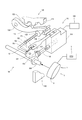
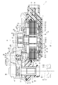
- FIG. 1 is a sectional view showing a rotary actuator according to the first embodiment.
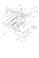
- FIG. 2 is a schematic diagram showing a shift-by-wire system to which the rotary actuator according to the first embodiment is applied.
- FIG. 3A is a front view showing the end of the shaft;
- FIG. 3B is a view of FIG. 3A as viewed from the direction of arrow IIIB.
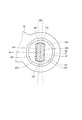
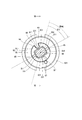
- FIG. 4 is a diagram of an output shaft and a shaft of the rotary actuator according to the first embodiment viewed from the axial direction.
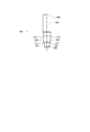
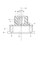
- FIG. 5 is a perspective view showing an output shaft of the rotary actuator according to the first embodiment, FIG.
- FIG. 6 is a view of the magnet holder of the rotary actuator according to the first embodiment as seen from the axial direction.
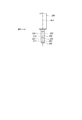
- 7 is a cross-sectional view taken along line VII-VII in FIG.
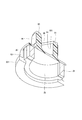
- FIG. 8 is a perspective view showing a magnet holder of the rotary actuator according to the first embodiment
- FIG. 9 is a perspective sectional view showing a magnet holder of the rotary actuator according to the first embodiment
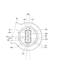
- FIG. 10 is a diagram of an output shaft and a shaft of the rotary actuator according to the second embodiment viewed from the axial direction.
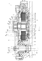
- FIG. 11 is a cross-sectional view showing a rotary drive device according to the third embodiment.
- FIG. 12 is a schematic view showing a shift-by-wire system to which the rotary drive device according to the third embodiment is applied.
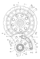
- FIG. 13 is a view of a part of the rotary drive device according to the third embodiment as seen from the direction of arrow XIII in FIG.
- FIG. 14 is a cross-sectional view showing a rotary drive device according to the fourth embodiment
- FIG. 15 is a view of FIG. 14 viewed from the direction of the arrow XV.
- FIG. 16 is a cross-sectional view showing a rotary drive device according to the fifth embodiment.
- a rotary actuator according to a plurality of embodiments will be described below with reference to FIGS.
- substantially the same components are denoted by the same reference numerals and description thereof is omitted.
- substantially the same constituent parts have the same or similar operational effects.
- the rotary actuator 1 shown in FIG. 1 is applied as a drive unit of a shift-by-wire system that switches a shift of an automatic transmission of a vehicle, for example.
- the shift-by-wire system 100 includes a rotary actuator 1, an electronic control unit (hereinafter referred to as "ECU") 2, a shift range switching device 110, a parking switching device 120, and the like.
- the rotary actuator 1 rotationally drives the manual shaft 200 of the shift range switching device 110 as a drive target.
- the rotation of the rotary actuator 1 is controlled by the ECU 2.
- the rotary actuator 1 is attached to the wall 130 of the shift range switching device 110 as an attachment target, for example.
- the rotary actuator 1 drives the park rod 121 and the like of the parking switching device 120 by rotationally driving the manual shaft 200 of the shift range switching device 110.
- the manual shaft 200 corresponds to a “shaft”.
- the shift range switching device 110 includes a manual shaft 200, a detent plate 102, a hydraulic valve body 104, a wall 130, and the like.
- the wall 130 accommodates the manual shaft 200, the detent plate 102, the hydraulic valve body 104, and the like.
- the manual shaft 200 is provided such that one end protrudes from the wall 130 via a hole 131 (see FIG. 1) formed in the wall 130.
- the manual shaft 200 has one end fitted to the output shaft 80 of the rotary actuator 1 (described later).
- the detent plate 102 is formed in a fan shape extending radially outward from the manual shaft 200 and rotates integrally with the manual shaft 200.
- the detent plate 102 is provided with a pin 103 that protrudes in parallel with the manual shaft 200.
- the pin 103 is locked to an end portion of a manual spool valve 105 provided in the hydraulic valve body 104. For this reason, the manual spool valve 105 reciprocates in the axial direction by the detent plate 102 that rotates integrally with the manual shaft 200. The manual spool valve 105 reciprocates in the axial direction to switch the hydraulic pressure supply path to the hydraulic clutch of the automatic transmission 108. As a result, the engagement state of the hydraulic clutch is switched, and the shift range of the automatic transmission 108 is changed.
- the detent plate 102 has a concave portion 151, a concave portion 152, a concave portion 153, and a concave portion 154 at the end portion in the radial direction.
- the concave portions 151 to 154 correspond to, for example, the P range, the R range, the N range, and the D range, which are shift ranges of the automatic transmission 108, respectively.
- the stopper 107 supported at the tip of the leaf spring 106 is fitted into any of the recesses 151 to 154 of the detent plate 102, the position of the manual spool valve 105 in the axial direction is determined. At this time, the rotational position of the manual shaft 200 is held at a predetermined position.
- the detent plate 102, the leaf spring 106, and the stopper 107 constitute a “holding mechanism”, and the manual shaft 200 can be positioned by holding the rotational position of the manual shaft 200 at a predetermined position.
- the pin 103 pushes the manual spool valve 105 into the hydraulic valve body 104 via the detent plate 102, and the hydraulic valve body 104
- the inner oil passage is switched in the order of D, N, R, and P.
- the shift range of the automatic transmission 108 is switched in the order of D, N, R, and P.
- the pin 103 pulls out the manual spool valve 105 from the hydraulic valve body 104, and the oil passage in the hydraulic valve body 104 is switched in the order of P, R, N, and D. .
- the shift range of the automatic transmission 108 is switched in the order of P, R, N, and D.
- the rotation angle of the manual shaft 200 driven to rotate by the rotary actuator 1, that is, a predetermined position in the rotation direction corresponds to each shift range of the automatic transmission 108.
- the parking switching device 120 includes a park rod 121, a park pole 123, a parking gear 126, and the like.
- the park rod 121 is formed in a substantially L shape, and the detent plate 102 is connected to one end thereof.
- a conical portion 122 is provided at the other end of the park rod 121.
- a protrusion 125 is provided in the rotation direction of the park pole 123.
- the rotation of the parking gear 126 is restricted.
- the driving wheel is locked via a drive shaft or a differential gear (not shown).
- the projection 125 of the park pole 123 is disengaged from the gear of the parking gear 126, the parking gear 126 becomes rotatable and the lock of the driving wheel is released.
- the rotary actuator 1 includes a housing 10, an input shaft 20, a motor 3, a speed reducer 50 as a gear mechanism, an output gear 60, an output shaft 80, a magnet holder 90, a washer 922, a spring 94, and a magnet. 35, an angle sensor 45, and the like.
- the housing 10 includes a front housing 11, a rear housing 12, and a cover 13.
- the front housing 11 is made of, for example, resin.
- the rear housing 12 is made of a metal such as aluminum.
- the cover 13 is formed in a plate shape from, for example, metal.
- the front housing 11 and the rear housing 12 are each formed in a bottomed cylindrical shape.
- the front housing 11 and the rear housing 12 are fixed by bolts 4 in a state where the openings are joined to each other. Thereby, a space 5 is formed between the front housing 11 and the rear housing 12.
- the cover 13 is provided so as to cover the opposite side of the rear housing 12 from the front housing 11.
- the rotary actuator 1 is attached to the wall 130 such that the surface of the front housing 11 opposite to the rear housing 12 faces the wall 130 of the shift range switching device 110.
- the input shaft 20 is made of, for example, metal.
- the input shaft 20 has one end portion 21, a large diameter portion 22, an eccentric portion 23, and the other end portion 24.
- the one end portion 21, the large diameter portion 22, the eccentric portion 23, and the other end portion 24 are integrally formed so as to be aligned in the direction of the axis Ax1 in this order.
- the one end portion 21 is formed in a columnar shape.
- the large-diameter portion 22 is formed in a columnar shape having an outer diameter larger than that of the one end portion 21, and is provided coaxially with the one end portion 21 (axis Ax1).
- the eccentric portion 23 is formed in a columnar shape having an outer diameter smaller than that of the large diameter portion 22, and is provided eccentric to the axis Ax ⁇ b> 1 that is the rotation center of the input shaft 20. That is, the eccentric portion 23 is provided eccentric to the one end portion 21 and the large diameter portion 22.
- the other end portion 24 is formed in a cylindrical shape having an outer diameter smaller than that of the eccentric portion 23, and is provided coaxially with the one end portion 21 and the large diameter portion 22 (axis Ax1).
- the input shaft 20 is rotatably supported at the other end 24 by the front bearing 16 and at the one end 21 by the rear bearing 17.
- the front bearing 16 and the rear bearing 17 are, for example, ball bearings.
- the front bearing 16 is provided inside an output gear 60 described later.
- the output gear 60 is rotatably supported by a metal cylindrical metal bearing 18 provided inside the front housing 11. That is, the other end 24 of the input shaft 20 is rotatably supported via the metal bearing 18, the output gear 60, and the front bearing 16 provided in the front housing 11.
- one end 21 of the input shaft 20 is rotatably supported via a rear bearing 17 provided at the bottom of the rear housing 12.
- the input shaft 20 is rotatably supported by the housing 10.
- the motor 3 is, for example, a three-phase brushless motor.
- the motor 3 is provided on the rear housing 12 side of the space 5. That is, the motor 3 is provided so as to be accommodated in the housing 10.
- the motor 3 includes a stator 30, a coil 33, and a rotor 40.
- the stator 30 is formed in a substantially annular shape, and is fixed to the rear housing 12 so as not to rotate by being press-fitted into a metal plate 8 fixed to the rear housing 12.
- the stator 30 is made of a magnetic material such as iron.
- the stator 30 has a stator core 31 and stator teeth 32.
- the stator core 31 is formed in an annular shape.
- the stator teeth 32 are formed so as to protrude radially inward from the stator core 31.
- a plurality of stator teeth 32 are formed at equal intervals in the circumferential direction of the stator core 31.
- the coil 33 is provided so as to be wound around each of the plurality of stator teeth 32.
- the coil 33 is electrically connected to the bus bar portion 70.
- the bus bar portion 70 is provided at the bottom of the rear housing 12.
- the electric power supplied to the coil 33 flows through the bus bar portion 70.
- the bus bar portion 70 has a terminal 71 connected to the coil 33.
- the coil 33 is electrically connected to the terminal 71. Electric power is supplied to the terminal 71 based on the drive signal output from the ECU 2.
- the rotor 40 is provided inside the stator 30 in the radial direction.
- the rotor 40 has a rotor core 41 and a magnet 42.
- the rotor core 41 is formed by laminating a plurality of thin plates made of a magnetic material such as iron in the thickness direction.
- the rotor core 41 is formed in an annular shape and is press-fitted and fixed to the large-diameter portion 22 of the input shaft 20.
- the magnet 42 is formed in an annular shape and is provided on the radially outer side of the rotor core 41.
- the magnet 42 is magnetized so that N poles and S poles are alternately arranged in the circumferential direction.
- the rotor 40 can be rotated relative to the housing 10 and the stator 30 together with the input shaft 20 by press-fitting and fixing the rotor core 41 to the input shaft 20.
- the plurality of coils 33 constitute, for example, three phases of U phase, V phase, and W phase.
- the ECU 2 switches the energization in the order of the U phase, the V phase, and the W phase, the rotor 40 rotates, for example, in one circumferential direction.
- the ECU 2 switches the energization in the order of the W phase, the V phase, and the U phase, the rotor 40 rotates in the circumferential direction. Rotate to the other.
- the rotor 40 can be rotated in an arbitrary direction by switching the energization to each coil 33 and controlling the magnetic force generated in the stator teeth 32.
- a relatively large cogging torque is generated by the magnetic force between the magnet 42 and the stator teeth 32. Therefore, when the motor 3 is not energized, the rotor 40 may be restrained at a predetermined rotational position.
- a rotary encoder 72 is provided between the bottom of the rear housing 12 and the rotor core 41.
- the rotary encoder 72 includes a magnet 73, a Hall IC 75, and the like.
- the magnet 73 is a multipolar magnet formed in an annular shape and having N and S poles alternately magnetized in the circumferential direction.
- the magnet 73 is disposed coaxially with the rotor core 41 at the end of the rotor core 41 on the rear housing 12 side.
- a substrate 74 is provided between the rear housing 12 and the cover 13.
- the Hall IC 75 is mounted on the substrate 74 so as to face the magnet 73.
- Hall IC 75 has a Hall element and a signal conversion circuit.
- the Hall element is a magnetoelectric conversion element using the Hall effect, and outputs an electrical signal proportional to the density of magnetic flux generated by the magnet 73.
- the signal conversion circuit converts the output signal of the Hall element into a digital signal.
- the Hall IC 75 outputs a pulse signal synchronized with the rotation of the rotor core 41 to the ECU 2.
- the ECU 2 can detect the rotation angle and direction of the rotor core 41 based on the pulse signal from the Hall IC 75.
- the reduction gear 50 has a ring gear 51 and a sun gear 52.
- the ring gear 51 is formed in an annular shape from a metal such as iron.
- the ring gear 51 is fixed to the rear housing 12 together with the plate 8 so as not to rotate.
- the ring gear 51 is fixed to the housing 10 so as to be coaxial with the input shaft 20 (axis Ax1).
- the ring gear 51 has internal teeth 53 formed on the inner edge.
- the sun gear 52 is formed in a substantially disc shape with a metal such as iron.
- the sun gear 52 has a columnar protruding portion 54 formed so as to protrude in the plate thickness direction from a position separated from the center of one surface by a predetermined distance radially outward.
- a plurality of the protrusions 54 are formed at equal intervals in the circumferential direction of the sun gear 52.
- the sun gear 52 has external teeth 55 formed on the outer edge so as to mesh with the internal teeth 53 of the ring gear 51.
- the sun gear 52 is provided so as to be eccentric relative to the input shaft 20 via a middle bearing 19 provided on the outer periphery of the eccentric portion 23 of the input shaft 20.
- the middle bearing 19 is, for example, a ball bearing, similarly to the front bearing 16 and the rear bearing 17.
- the output gear 60 is made of, for example, metal.
- the output gear 60 has a substantially cylindrical output tube portion 61 and a substantially disc-shaped disc portion 62.
- the output cylinder portion 61 is rotatably supported by the housing 10 via a metal bearing 18 provided inside the front housing 11.
- the output cylinder part 61 is provided so as to be coaxial with the large diameter part 22 of the input shaft 20.
- a front bearing 16 is provided inside the output cylinder portion 61. Thereby, the output cylinder part 61 is supporting the other end part 24 of the input shaft 20 through the metal bearing 18 and the front bearing 16 so that rotation is possible.
- the disk part 62 is formed in a substantially disk shape so as to expand radially outward from the end part on the sun gear 52 side of the output cylinder part 61.
- the disk portion 62 is formed with a hole portion 63 into which the protruding portion 54 of the sun gear 52 can enter.
- the hole part 63 is formed so as to penetrate the disk part 62 in the plate thickness direction.
- a plurality of hole parts 63 are formed in the circumferential direction of the disk part 62 corresponding to the protrusions 54.
- External teeth 64 are formed on the outer edge portion of the disk portion 62 over the entire circumferential range.
- the output shaft 80 includes a shaft tube portion 81, a gear portion 82, a shaft hole portion 83, and the like.
- the shaft cylinder part 81 and the gear part 82 are made of, for example, metal.
- the shaft cylinder part 81 is formed in a bottomed cylinder shape, for example.
- the gear portion 82 is formed integrally with the shaft tube portion 81 so as to extend in a generally fan shape from the outer peripheral wall at the end opposite to the bottom portion of the shaft tube portion 81 to the radially outer side.
- External teeth 84 are formed on the outer edge portion of the gear portion 82 opposite to the shaft cylinder portion 81.
- the output shaft 80 is provided in the space 5 between the front housing 11 and the rear housing 12 so that the external teeth 84 mesh with the external teeth 64 of the output gear 60.
- the output shaft 80 is provided such that the axis Ax2 of the shaft tube portion 81 is substantially parallel to the axis Ax1 of the input shaft 20.
- the output shaft 80 is provided such that the shaft cylinder portion 81 is positioned inside a cylindrical metal bearing 87 provided in the front housing 11. Thereby, the output shaft 80 is rotatably supported by the front housing 11 via the metal bearing 87.
- the shaft hole portion 83 is formed so as to penetrate the bottom portion of the shaft tube portion 81 in the axial direction. That is, the shaft hole portion 83 is formed so as to penetrate the shaft tube portion 81 of the output shaft 80 in the direction of the axis Ax2. The shape and the like of the shaft hole 83 will be described later in detail.
- one end of the manual shaft 200 of the shift-by-wire system 100 is fitted into the shaft hole 83 of the output shaft 80, whereby the output shaft 80 and the manual shaft 200 are coupled.
- the output shaft 80 outputs the torque of the motor 3 to the manual shaft 200 by transmitting the rotation of the input shaft 20 via the speed reducer 50 and the output gear 60.
- the manual shaft 200 includes a first fitting portion 201, a second fitting portion 202, a tapered portion 203, and the like.
- the first fitting portion 201 is formed on one end side of the manual shaft 200.
- the second fitting portion 202 is formed on the other end side of the manual shaft 200 with respect to the first fitting portion 201.
- the tapered portion 203 is formed on the opposite side of the first fitting portion 201 from the second fitting portion 202.
- the tapered portion 203 is formed in a tapered shape so as to approach the axis Ax3 of the manual shaft 200 as it goes from the other end side of the manual shaft 200 to the one end side.
- the first fitting portion 201 is formed with a first curved surface portion 211 and a first flat surface portion 221.
- the first curved surface portion 211 is formed so as to coincide with a part of a virtual cylindrical surface centered on the axis Ax3. Note that the diameter of the virtual cylindrical surface is smaller than the diameter of the manual shaft 200.
- Two first curved surface portions 211 are formed in the first fitting portion 201 so as to sandwich the axis Ax3.
- Two first flat portions 221 are formed in the first fitting portion 201 so as to sandwich the axis Ax3 between the two first curved surface portions 211.
- the two first plane portions 221 are each formed to be planar and parallel to each other.
- the 1st fitting part 201 is formed in what is called a 2 surface shape. As shown in FIG. 3A, the distance between the two first flat portions 221 is smaller than the diameter of the manual shaft 200.
- a second curved surface portion 212 and a second flat surface portion 222 are formed in the second fitting portion 202.
- the second curved surface portion 212 is formed so as to coincide with a part of the virtual cylindrical surface with the axis Ax3 as the center. Note that the diameter of the virtual cylindrical surface is smaller than the diameter of the manual shaft 200.
- Two second curved surface portions 212 are formed in the second fitting portion 202 so as to sandwich the axis Ax3.
- Two second flat portions 222 are formed in the second fitting portion 202 so as to sandwich the axis Ax3 between the two second curved surface portions 212.
- the two second flat portions 222 are formed so as to be planar and parallel to each other.
- the 2nd fitting part 202 is formed in what is called a 2 surface shape. As shown in FIG. 3A, the distance between the two second plane portions 222 is smaller than the diameter of the manual shaft 200 and is substantially equal to the distance between the two first plane portions 221.
- the manual shaft 200 is fitted to the output shaft 80 so that the second fitting portion 202 is positioned inside the shaft hole portion 83 of the output shaft 80.
- the second fitting portion 202 of the manual shaft 200 is formed so that a cross section perpendicular to the axis Ax3 is curved at the second curved surface portion 212 and linear at the second flat surface portion 222. Yes.
- the shaft hole portion 83 of the output shaft 80 has a shaft hole curved surface portion 831 and a shaft hole flat surface portion 832.
- the shaft hole curved surface portion 831 is formed so as to coincide with a part of a virtual cylindrical surface centering on the axis Ax2 of the shaft tube portion 81.
- Two shaft hole curved surface portions 831 are formed in the shaft hole portion 83 so as to sandwich the axis Ax2.
- Two shaft hole plane portions 832 are formed in the shaft hole portion 83 so as to sandwich the axis Ax2 between the two shaft hole curved surface portions 831.
- the two axial hole plane portions 832 are each formed to be planar and parallel to each other.
- the shaft hole portion 83 corresponds to the shape of the second fitting portion 202 and is formed in a so-called two-surface shape.
- the distance between the two shaft hole curved surface portions 831 of the output shaft 80 is set to be slightly larger than the distance between the two second curved surface portions 212 of the manual shaft 200.
- the distance between the two shaft hole plane portions 832 of the output shaft 80 is set to be larger than the distance between the two second plane portions 222 of the manual shaft 200. Therefore, the manual shaft 200 can rotate relative to the output shaft 80 inside the shaft hole 83.
- the shaft hole curved surface portion 831 and the second curved surface portion 212 can slide.
- the second flat surface portion 222 of the manual shaft 200 can be brought into contact with the shaft hole flat surface portion 832 of the shaft hole portion 83 only at the end portion on the second curved surface portion 212 side.
- a predetermined amount of play ⁇ 0 that is equal to or greater than the first predetermined value is set between the manual shaft 200 and the output shaft 80.
- the first predetermined value is a value larger than zero. That is, the manual shaft 200 can be relatively rotated with respect to the output shaft 80 in the angle range of the backlash ⁇ 0 inside the shaft hole 83 (see FIG. 4).
- a rotation restricting hole 85 is formed on the end surface opposite to the bottom of the shaft tube portion 81.
- the rotation restricting hole 85 is formed so as to be recessed from the end surface opposite to the bottom of the shaft tube portion 81 toward the bottom.
- the magnet holder 90 is formed separately from the output shaft 80.
- the magnet holder 90 includes a first holder cylinder 91, a second holder cylinder 92, a holder extension 921, a holder hole 93, a slit 95, a taper 96, and the like.
- the 1st holder cylinder part 91 and the 2nd holder cylinder part 92 are formed, for example with resin. That is, the magnet holder 90 is formed of a material within a predetermined range whose elastic modulus is lower than that of a general metal and higher than that of a general rubber, for example.
- the 1st holder cylinder part 91 is formed in the substantially cylindrical shape, for example.
- the 2nd holder cylinder part 92 is formed in the bottomed substantially cylindrical shape.
- the first holder tube portion 91 is formed integrally with the second holder tube portion 92 so as to extend from the bottom portion of the second holder tube portion 92 to the side opposite to the tube portion of the second holder tube portion 92.
- the 1st holder cylinder part 91 and the 2nd holder cylinder part 92 are provided coaxially (Ax4).
- the holder extending portion 921 is formed so as to extend annularly outward in the radial direction from the outer peripheral wall of the end portion of the second holder tube portion 92 opposite to the first holder tube portion 91.
- the magnet holder 90 is provided between the output shaft 80 and the rear housing 12. More specifically, in the magnet holder 90, the first holder tube portion 91 is positioned inside the end portion of the output shaft 80 opposite to the bottom portion of the shaft tube portion 81, and the bottom portion of the second holder tube portion 92 is the shaft. It is provided coaxially with the shaft tube portion 81 so as to face or abut against the end surface opposite to the bottom portion of the tube portion 81.
- the holder hole 93 is formed inside the first holder cylinder 91. That is, one end of the holder hole 93 is closed by the bottom of the second holder tube 92.
- the holder hole 93 communicates with the shaft hole 83 of the output shaft 80.
- the holder hole portion 93 of the magnet holder 90 has a holder hole flat portion 931.
- Two holder hole flat portions 931 are formed in the holder hole portion 93 so as to sandwich the axis Ax4 of the magnet holder 90 therebetween.
- the two holder hole plane portions 931 are formed so as to be planar and parallel to each other.
- the holder hole 93 is formed in a so-called two-surface shape.
- the slit 95 is formed in the first holder tube portion 91.
- the slit 95 is formed in a cutout shape in a part of the first holder cylinder portion 91 in the circumferential direction. That is, the slit 95 is formed so as to cut out a part of the holder hole 93 in the circumferential direction.
- two slits 95 are formed at equal intervals in the circumferential direction of the first holder tube portion 91. That is, two slits 95 are formed in the first holder cylinder portion 91 so as to sandwich the axis Ax4 of the magnet holder 90 therebetween.
- the two slits 95 are formed in the holder hole portion 93 between the two holder hole plane portions 931. Due to the slit 95, the first holder tube portion 91 is easily deformed radially inward.
- the taper portion 96 has a shaft (Ax4) of the holder hole portion 93 as it goes from the shift range switching device 110 side to the opposite side of the shift range switching device 110 at the portion of the holder hole portion 93 on the manual shaft 200 side of the shift range switching device 110. It is formed in a taper shape so as to be close to As shown in FIGS. 1 and 6, in the present embodiment, the manual shaft 200 is fitted to the magnet holder 90 so that the first fitting portion 201 is positioned inside the holder hole 93 of the magnet holder 90. As shown in FIG. 6, the first fitting portion 201 of the manual shaft 200 is formed so that a cross section perpendicular to the axis Ax3 is curved at the first curved surface portion 211 and linear at the first flat surface portion 221. Yes.
- the manual shaft 200 passes through the shaft hole 83 of the output shaft 80, and the shaft 203 is in contact with the taper 96 of the magnet holder 90. Move relative to the Ax3 direction.
- the rotation angle of the manual shaft 200 is an angle at which the first flat surface portion 221 and the holder hole flat surface portion 931 do not correspond, the magnet so that the first flat surface portion 221 and the holder hole flat surface portion 931 correspond.
- the manual shaft 200 rotates relative to the holder 90 (see FIG. 6).
- the distance between the two holder hole plane portions 931 of the holder hole portion 93 is set to be the same as or slightly smaller than the distance between the two first plane portions 221 of the manual shaft 200. Further, the distance between the two slits 95 of the holder hole 93 is set to be the same as or slightly smaller than the distance between the two first curved surfaces 211 of the manual shaft 200. Therefore, in the manual shaft 200, the first flat surface portion 221 and the holder hole flat surface portion 931 are in close contact with each other in a state where the first fitting portion 201 is fitted in the holder hole portion 93, and the first curved surface portion 211 and the holder The part of the slit 95 of the hole 93 is in close contact.
- the magnet holder 90 and the manual shaft 200 are not relatively rotatable. Therefore, the magnet holder 90 rotates integrally with the manual shaft 200.
- the backlash amount between the manual shaft 200 and the holder hole 93 is set to zero. That is, the backlash between the manual shaft 200 and the holder hole 93 is set to be equal to or less than the second predetermined value.
- the second predetermined value is zero. That is, the backlash between the manual shaft 200 and the holder hole 93 is zero.
- the rear housing 12 has a thrust load receiving portion 14.
- the thrust load receiving portion 14 is formed at a position facing the holder extending portion 921 of the magnet holder 90 on the surface of the rear housing 12 on the front housing 11 side.
- the washer 922 is formed in a substantially annular shape by a thin metal plate, for example. For example, a fluororesin is applied to the washer 922.
- the washer 922 is provided between the holder extending portion 921 and the thrust load receiving portion 14. For example, when the operator fits the manual shaft 200 into the holder hole 93, the axial load from the magnet holder 90 acts on the thrust load receiver 14 via the washer 922.
- the washer 922 can suppress wear of the magnet holder 90. Further, since the washer 922 is coated with fluororesin, the frictional force between the thrust load receiving portion 14 of the rear housing 12 and the magnet holder 90 is reduced. Thereby, the magnet holder 90 can smoothly rotate relative to the rear housing 12.
- a rotation restricting pin 97 is formed on the magnet holder 90.
- the rotation restricting pin 97 is formed integrally with the second holder cylinder 92 so as to protrude from the bottom of the second holder cylinder 92 to the first holder cylinder 91 side.
- the magnet holder 90 and the output shaft 80 are assembled so that the rotation restriction pin 97 is fitted in the rotation restriction hole 85 of the output shaft 80. In this state, the relative rotation between the magnet holder 90 and the output shaft 80 is restricted.
- the rotation restricting pin 97 and the rotation restricting hole 85 correspond to a “rotation restricting portion”.
- a holder recess 911 is formed in the first holder tube portion 91.
- the holder recess 911 is formed so as to be recessed radially inward from the outer peripheral wall of the first holder tube portion 91.
- two holder recesses 911 are formed at equal intervals in the circumferential direction of the first holder tube portion 91.
- the holder recess 911 is formed between the two slits 95.
- the spring 94 is formed by, for example, winding a long metal thin plate approximately once in the longitudinal direction. Both ends in the longitudinal direction of the spring 94 are bent inward in the radial direction.
- the spring 94 is provided on the outer side in the radial direction of the first holder tube portion 91 so that both end portions are locked by one holder recess 911.
- a biasing force radially inward from the spring 94 is applied to the first holder tube portion 91. Accordingly, the spring 94 can tighten the first holder tube portion 91 to the manual shaft 200 in a state where the manual shaft 200 is fitted in the holder hole portion 93.
- the magnet holder 90 is provided with two yokes 36.
- the yoke 36 is formed in a substantially arc shape from a magnetic material such as iron.
- the yoke 36 is provided on the inner side of the second holder cylinder portion 92 so as to form a gap while opposing both end portions thereof.
- Two magnets 35 are provided in total, one in the gap between the two end portions of the two yokes 36.
- the two magnets 35 are provided such that the magnetic poles abut against the end of the yoke 36. Thereby, the magnetic flux generated from the magnet 35 flows through the yoke 36.
- the magnetic flux flowing through the yoke 36 flies as a leakage magnetic flux in the space between the two yokes 36.
- the two yokes 36 and the two magnets 35 are not rotatable relative to the magnet holder 90 and rotate together with the magnet holder 90.
- the angle sensor 45 has a Hall element and a signal conversion circuit.
- the angle sensor 45 is provided so that the Hall element is located inside the second holder cylinder portion 92 of the magnet holder 90, that is, inside the two yokes 36 and the two magnets 35.
- the angle sensor 45 is supported by a support portion 46 attached to the rear housing 12.
- the angle sensor 45 is provided on the shaft cylinder portion 81 of the output shaft 80 and the shaft (Ax3, Ax4) of the magnet holder 90. That is, the magnet holder 90 and the angle sensor 45 are provided on the axis Ax2 of the manual shaft 200.
- the angle sensor 45 has a terminal connected to the Hall element and the signal conversion circuit connected to the substrate 74.
- the angle sensor 45 can detect a magnetic flux from the magnet 35 inside the two yokes 36 and output a signal corresponding to the rotation angle of the magnet holder 90 to the ECU 2. Thereby, the ECU 2 can detect the rotation angle of the magnet holder 90.
- the ECU 2 since the magnet holder 90 rotates integrally with the manual shaft 200, the ECU 2 can detect the rotation angle of the manual shaft 200 from the rotation angle of the magnet holder 90.
- the variation in the positioning accuracy of the manual shaft 200 in the holding mechanism (detent plate 102, leaf spring 106, stopper 107) when the manual shaft 200 is driven by the motor 3 is ⁇ 1, and the manual shaft 200 and the motor 3 When the backlash amount between them is ⁇ 2, ⁇ 1 ⁇ 2.
- ⁇ 2 is a backlash of a torque transmission path between the motor 3, the speed reducer 50, the output gear 60, the output shaft 80, and the manual shaft 200, that is, from the motor 3 to the manual shaft 200. Therefore, even if the motor 3 is in a stopped state, the manual shaft 200 can rotate within the range of ⁇ 2.
- the end of the manual shaft 200 moves in the axial direction while being in contact with the tapered portion 96, so that the magnet holder 90 and the manual shaft 200 are rotated relative to each other.
- the correction angle which is the maximum relative rotation angle is ⁇ 3
- the backlash amount between the magnet holder 90 and the output shaft 80 in the rotation restricting portion is ⁇ 4, ⁇ 3 ⁇ 4> ⁇ 2.
- the backlash ⁇ 0 between the manual shaft 200 and the output shaft 80 is smaller than ⁇ 4. Therefore, when the manual shaft 200 is rotated by the rotation of the output shaft 80, it is possible to suppress the stress from being generated in the magnet holder 90.
- the relative rotation between the magnet holder 90 and the output shaft 80 is restricted by the rotation restricting pin 97 and the rotation restricting hole 85, and the rotational positions of the holder hole 93 and the shaft hole 83 are adjusted. Therefore, the first fitting portion 201 can be easily fitted into the holder hole portion 93.
- the tapered portion 96 is formed on the magnet holder 90 and the tapered portion 203 is formed on the manual shaft 200, when the manual shaft 200 is fitted into the holder hole 93, the manual shaft 200 The magnet holder 90 and the manual shaft 200 rotate relative to each other when the tapered portion 203 at the end moves in the axial direction while contacting the tapered portion 96. Therefore, even if the relative angle between the manual shaft 200 and the holder hole 93 is inappropriate before the manual shaft 200 is fitted into the holder hole 93, the manual shaft 200 is corrected for the relative angle and the holder hole 93.
- the ECU 2 energizes the motor 3.
- the motor 3 rotates by energization of the motor 3
- the torque of the motor 3 is transmitted to the output shaft 80 via the speed reducer 50 and the output gear 60.
- the shaft hole flat portion 832 of the shaft hole portion 83 of the output shaft 80 is in contact with the second flat portion 222 of the second fitting portion 202 of the manual shaft 200. Rotate.
- the manual shaft 200 rotates and the stopper 107 of the holding mechanism moves in the recesses 151 to 154 of the detent plate 102.
- the ECU 2 stops energizing the motor 3.
- the stopper 107 is fitted into one of the recesses 151 to 154, and the rotational position of the manual shaft 200 is held at a predetermined position.
- the magnet holder 90 rotates integrally with the manual shaft 200.
- the ECU 2 can detect the rotation angle of the manual shaft 200 based on a signal from the angle sensor 45.
- the present embodiment is the rotary actuator 1 capable of rotationally driving the manual shaft 200 of the shift range switching device 110, and includes the housing 10, the motor 3, the output shaft 80, the magnet holder 90, and the magnet 35. And an angle sensor 45.
- the motor 3 is provided in the housing 10.
- the output shaft 80 has a shaft hole portion 83 into which the manual shaft 200 can be fitted.
- the output shaft 80 rotates by torque output from the motor 3 and outputs torque to the manual shaft 200.
- the magnet holder 90 is formed separately from the output shaft 80, has a holder hole 93 into which the manual shaft 200 can be fitted, and is provided so as to be rotatable together with the manual shaft 200.
- the magnet 35 is provided on the magnet holder 90.
- the angle sensor 45 can detect a magnetic flux from the magnet 35 and output a signal corresponding to the rotation angle of the magnet holder 90. Thereby, the rotation angle of the manual shaft 200 can be detected.
- the backlash between the manual shaft 200 and the shaft hole 83 is set to be equal to or greater than a first predetermined value. Therefore, the manual shaft 200 can be easily fitted into the shaft hole portion 83, and the assembling property between the manual shaft 200 and the output shaft 80 can be improved.
- the backlash between the manual shaft 200 and the holder hole 93 is set to be equal to or less than the second predetermined value. Thereby, the relative rotation of the manual shaft 200 and the magnet holder 90 is restricted, and the magnet holder 90 can rotate integrally with the manual shaft 200. Therefore, the detection accuracy of the rotation angle of the manual shaft 200 by the angle sensor 45 can be increased.
- the output shaft 80 and the magnet holder 90 are formed separately. For this reason, the output shaft 80 and the magnet holder 90 can be rotated relative to each other, and when the output shaft 80 and the manual shaft 200 are rotated relative to each other within a range of backlash, the magnet holder 90 can be prevented from being stressed.
- the output shaft 80 is provided between the magnet holder 90 and the shift range switching device 110. Therefore, the magnet holder 90 can be disposed at the tip of the manual shaft 200, and the angle sensor 45 can be disposed inside the magnet holder 90, so that the rotary actuator 1 can be reduced in size.
- the shaft hole 83 is formed so as to penetrate the output shaft 80 in the axial direction. Therefore, the rotary actuator 1 can be reduced in size and thickness.
- the magnet holder 90 and the angle sensor 45 are provided on the axis of the manual shaft 200. Therefore, the axial deviation of the magnet holder 90, the angle sensor 45, and the manual shaft 200 can be suppressed, and the detection accuracy of the angle sensor 45 can be improved. Thereby, the rotation angle of the manual shaft 200 can be detected with high accuracy.
- the magnet holder 90 is formed of a material having an elastic modulus within a predetermined range. Therefore, the play between the magnet holder 90 and the manual shaft 200 can be eliminated, and the detection accuracy of the rotation angle of the manual shaft 200 can be further improved.
- the embodiment further includes a spring 94.
- the spring 94 is provided on the outer side in the radial direction of the holder hole 93, and can clamp the magnet holder 90 to the manual shaft 200. Therefore, the magnet holder 90 and the manual shaft 200 can be securely fixed and vibration resistance can be improved. Thereby, the detection accuracy of the rotation angle of the manual shaft 200 can be further improved.
- the magnet holder 90 has a notch-shaped slit 95 in a part of the holder hole 93 in the circumferential direction. Therefore, the holder hole 93 can be easily deformed, and the play between the magnet holder 90 and the manual shaft 200 can be eliminated while accommodating the dimensional variation of the manual shaft 200.
- the housing 10 has a thrust load receiving portion 14 to which an axial load from the magnet holder 90 acts.
- the present embodiment further includes a washer 922 provided between the magnet holder 90 and the thrust load receiving portion 14. Therefore, it is possible to fit and fasten the manual shaft 200 and the magnet holder 90 only by attaching the rotary actuator 1 to the shift range switching device 110 with the manual shaft 200 and the shaft hole 83 corresponding to each other. Can be improved. Further, the washer 922 can suppress wear of the magnet holder 90.
- the shift range switching device 110 has a detent plate 102, a leaf spring 106, and a stopper 107 as a holding mechanism that can position the manual shaft 200 by holding the rotational position of the manual shaft 200 at a predetermined position. have.
- the variation of the positioning accuracy of the manual shaft 200 in the holding mechanism when the manual shaft 200 is driven by the motor 3 is ⁇ 1
- the amount of play between the manual shaft 200 and the motor 3 is ⁇ 2, ⁇ 1 ⁇ 2.
- the stopper 107 of the holding mechanism fits into the recesses 151 to 154 of the detent plate 102 with high accuracy, and a reduction in the positioning accuracy of the shift position can be suppressed.
- this embodiment even when the motor 3 is de-energized, the stopper 107 of the holding mechanism fits into the recesses 151 to 154 of the detent plate 102 with high accuracy even if the rotor 40 is restrained to a predetermined rotational position. Can do. Therefore, this embodiment is suitable for the motor 3 having the magnet 42 and generating a relatively large cogging torque.
- the magnet holder 90 is configured such that the holder hole 93 has a portion of the holder hole 93 as it moves from the shift range switching device 110 side to the side opposite to the shift range switching device 110 at the shift range switching device 110 side. It has a tapered portion 96 formed in a tapered shape so as to approach the shaft. Therefore, when the manual shaft 200 is fitted in the holder hole 93, the magnet holder 90 and the manual shaft 200 are relatively moved by moving the taper portion 203 at the end of the manual shaft 200 in the axial direction while contacting the taper portion 96. Rotate.
- the present embodiment further includes a rotation restriction pin 97 and a rotation restriction hole 85 as a rotation restriction portion.
- the rotation restricting pin 97 and the rotation restricting hole 85 can restrict the relative rotation between the magnet holder 90 and the output shaft 80. Therefore, the manual shaft 200 can be easily fitted to the shaft hole 83 and the holder hole 93 by restricting the relative rotation within a range in which the relative rotation positions of the holder hole 93 and the shaft hole 83 are substantially corresponding. Can be made. Thereby, assembly
- the shaft of the manual shaft 200 is in contact with the tapered portion 96 while the manual shaft 200 is fitted in the holder hole 93.
- the correction angle which is the maximum relative rotation angle when the magnet holder 90 and the manual shaft 200 rotate relative to each other by moving in the direction, is ⁇ 3, the rotation restriction pin 97, the magnet holder 90 and the output shaft 80 in the rotation restriction hole 85, If the backlash amount is ⁇ 4, then ⁇ 3 ⁇ 4> ⁇ 2. Therefore, the angle between the manual shaft 200 and the magnet holder 90 can be adjusted by simply attaching the rotary actuator 1 to the shift range switching device 110 by making the manual shaft 200 and the shaft hole 83 correspond to each other, thereby improving the assembling property. can do.
- FIG. 8 A part of the rotary actuator according to the second embodiment is shown in FIG.
- the second embodiment is different from the first embodiment in the shape of the shaft hole portion 83 of the output shaft 80.
- the shaft hole portion 83 of the output shaft 80 includes a shaft hole curved surface portion 831, a first shaft hole flat surface portion 833, and a second shaft hole flat surface portion 834.
- the shaft hole curved surface portion 831 is formed so as to coincide with a part of a virtual cylindrical surface centering on the axis Ax ⁇ b> 2 of the shaft tube portion 81.
- Two shaft hole curved surface portions 831 are formed in the shaft hole portion 83 so as to sandwich the axis Ax2.
- Two first shaft hole plane portions 833 are formed in the shaft hole portion 83 so as to extend from the end portion in the circumferential direction of one shaft hole curved surface portion 831 to the other shaft hole curved surface portion 831 side.
- the two first axial hole plane portions 833 are formed in a planar shape so as to extend from different axial hole curved surface portions 831.
- the two first axial hole plane portions 833 are formed to be parallel to each other with the axis Ax2 interposed therebetween.
- the second axial hole plane part 834 extends from the end opposite to the first axial hole plane part 833 in the circumferential direction of one axial hole curved surface part 831 to the other axial hole curved surface part 831 side.
- Two shaft hole portions 83 are formed so as to be connected to the plane portion 833.
- the two second axial hole plane portions 834 are formed in a planar shape so as to extend from different axial hole curved surface portions 831.
- the two second axial hole plane portions 834 are formed to be parallel to each other with the axis Ax2 interposed therebetween.
- the first shaft hole flat surface portion 833 and the second shaft hole flat surface portion 834 facing each other are formed so as to approach each other from the shaft hole curved surface portion 831 toward the axis Ax2 side.
- the shaft hole portion 83 is formed so that the cross-sectional shape perpendicular to the axis Ax2 is a drum shape.
- the distance between two virtual planes each including two first axial hole plane parts 833 and the distance between two virtual planes including two second axial hole plane parts 834 are the two The distance is set to be approximately the same as the distance between the two plane portions 222.
- the shaft hole curved surface portion 831 and the second curved surface portion 212 can slide.
- the second flat surface portion 222 of the manual shaft 200 can come into surface contact with the first axial hole flat surface portion 833 or the second axial hole flat surface portion 834.
- the second flat surface portion 222 comes into surface contact with the first axial hole flat surface portion 833 or the second axial hole flat surface portion 834, the relative rotation between the output shaft 80 and the manual shaft 200 is restricted.
- the second embodiment is the same as the first embodiment except for the points described above. Therefore, 2nd Embodiment can have the same effect as 1st Embodiment.
- a predetermined amount of play ⁇ 0 that is equal to or greater than the first predetermined value is set as in the first embodiment.
- the first predetermined value is a value larger than zero. That is, the manual shaft 200 can be rotated relative to the output shaft 80 within the angle range of the backlash ⁇ 0 inside the shaft hole 83 (see FIG. 10).
- the output shaft 80 may be provided on the opposite side of the shift range switching device 110 with respect to the magnet holder 90. That is, the magnet holder 90 may be provided between the output shaft 80 and the shift range switching device 110.
- the holder hole 93 is formed so as to penetrate the magnet holder 90 in the axial direction, and the manual shaft 200 through which the holder hole 93 is inserted may be fitted into the shaft hole 83 of the output shaft 80.
- the angle sensor 45 cannot be arranged on the axis of the manual shaft 200, so it is necessary to arrange it near the yoke 36 other than the axis of the manual shaft 200.
- the magnet holder 90 is not limited to a resin as long as the elastic modulus is a material within a predetermined range, for example, a nonmagnetic metal such as brass or stainless steel, or a predetermined elastic modulus. You may form with the rubber
- the magnet holder 90 may be formed of metal, and rubber or resin may be applied to the holder hole 93. In such a configuration, the relative rotation between the manual shaft 200 and the magnet holder 90 can be restricted without degrading the assembling property between the manual shaft 200 and the magnet holder 90.
- the output shaft 80 and the magnet holder 90 may be integrally formed of, for example, the same material or different materials. Even if the output shaft 80 and the magnet holder 90 are integrally formed, the backlash between the manual shaft 200 and the shaft hole 83 is set to a first predetermined value or more, and the manual shaft 200 and the holder hole 93 If the backlash amount between the two is set to be equal to or smaller than the second predetermined value, the accuracy of detecting the rotation angle of the manual shaft 200 by the angle sensor 45 can be improved while improving the ease of assembly of the manual shaft 200 and the output shaft 80. Can do.
- the spring 94 may not be provided.
- the magnet holder 90 may not have the slit 95.
- the washer 922 is not limited to a metal, and may be formed of, for example, a fluororesin. Further, the washer 922 may not be provided. In other embodiments of the present disclosure, the magnet holder 90 may not have the tapered portion 96.
- the manual shaft 200 may not have the tapered portion 203.
- the rotation restricting portion (the rotation restricting pin 97 and the rotation restricting hole 85) may not be provided.
- the output shaft 80 and the manual shaft 200 may be fitted by, for example, spline fitting.
- the motor 3 is not limited to the three-phase brushless motor having the magnet 42, and may be another type of motor such as an SR motor.
- any number of the concave portions of the detent plate may be formed. That is, the number of ranges of the automatic transmission to which the present disclosure can be applied is not limited to four.
- the shift-by-wire system according to the present disclosure is similar to the above-described embodiment, and is an automatic of a continuously variable transmission (CVT) or HV (hybrid vehicle) that switches four positions “P”, “R”, “N”, and “D”.
- CVT continuously variable transmission
- HV hybrid vehicle
- the rotary actuator may use a device other than the shift range switching device or the parking switching device of the vehicle shift-by-wire system as a drive target and an attachment target.
- the present disclosure is not limited to the above-described embodiment, and can be implemented in various forms without departing from the gist thereof.
- a rotary actuator 1 as a rotary drive device shown in FIG. 11 is applied as a drive unit of a shift-by-wire system that switches a shift of an automatic transmission of a vehicle, for example.
- the shift-by-wire system 100 includes a rotary actuator 1, an electronic control unit (hereinafter referred to as "ECU") 2, a shift range switching device 110, a parking switching device 120, and the like.
- the rotary actuator 1 rotationally drives the manual shaft 101 of the shift range switching device 110 as a drive target.
- the rotation of the rotary actuator 1 is controlled by the ECU 2.
- the rotary actuator 1 is attached to the wall 130 of the shift range switching device 110 as an attachment target, for example.
- the rotary actuator 1 drives the park rod 121 and the like of the parking switching device 120 by rotationally driving the manual shaft 101 of the shift range switching device 110.
- the shift range switching device 110 includes a manual shaft 101, a detent plate 102, a hydraulic valve body 104, a wall portion 130, and the like.
- the wall 130 accommodates the manual shaft 101, the detent plate 102, the hydraulic valve body 104, and the like.
- the manual shaft 101 is provided such that one end protrudes from the wall 130 via a hole 131 (see FIG. 11) formed in the wall 130.
- the detent plate 102 is formed in a fan shape extending radially outward from the manual shaft 101 and rotates integrally with the manual shaft 101.
- the detent plate 102 is provided with a pin 103 that protrudes in parallel with the manual shaft 101.
- the pin 103 is locked to an end portion of a manual spool valve 105 provided in the hydraulic valve body 104.
- the manual spool valve 105 is reciprocated in the axial direction by the detent plate 102 that rotates integrally with the manual shaft 101.
- the manual spool valve 105 reciprocates in the axial direction to switch the hydraulic pressure supply path to the hydraulic clutch of the automatic transmission 108.
- the engagement state of the hydraulic clutch is switched, and the shift range of the automatic transmission 108 is changed.
- the detent plate 102 has a concave portion 151, a concave portion 152, a concave portion 153, and a concave portion 154 at the end portion in the radial direction.
- the concave portions 151 to 154 correspond to, for example, the P range, the R range, the N range, and the D range, which are shift ranges of the automatic transmission 108, respectively.
- the stopper 107 supported at the tip of the leaf spring 106 meshes with any of the recesses 151 to 154 of the detent plate 102, whereby the axial position of the manual spool valve 105 is determined.
- the pin 103 pushes the manual spool valve 105 into the hydraulic valve body 104 via the detent plate 102, and the hydraulic valve body 104
- the inner oil passage is switched in the order of D, N, R, and P.
- the shift range of the automatic transmission 108 is switched in the order of D, N, R, and P.
- the pin 103 pulls out the manual spool valve 105 from the hydraulic valve body 104, and the oil passage in the hydraulic valve body 104 is switched in the order of P, R, N, and D. .
- the shift range of the automatic transmission 108 is switched in the order of P, R, N, and D.
- the rotation angle of the manual shaft 101 that is rotationally driven by the rotary actuator 1, that is, a predetermined position in the rotation direction corresponds to each shift range of the automatic transmission 108.
- the parking switching device 120 includes a park rod 121, a park pole 123, a parking gear 126, and the like.
- the park rod 121 is formed in a substantially L shape, and the detent plate 102 is connected to one end thereof.
- a conical portion 122 is provided at the other end of the park rod 121.
- a protrusion 125 is provided in the rotation direction of the park pole 123.
- the rotation of the parking gear 126 is restricted.
- the driving wheel is locked via a drive shaft or a differential gear (not shown).
- the projection 125 of the park pole 123 is disengaged from the gear of the parking gear 126, the parking gear 126 becomes rotatable and the lock of the driving wheel is released.
- the rotary actuator 1 includes a housing 10, an input shaft 20, a motor 3 as a rotating electrical machine, a speed reducer 50 as a gear mechanism, an output shaft 60, an output gear 81, an output unit 86, a yoke 90, A magnet 93 as a first magnetic flux generator, a magnet 94 as a second magnetic flux generator, a Hall IC 141 as a magnetic flux density detector, first holes 811, 812, 813, second holes 821, 822, 823, etc. I have.
- the housing 10 includes a front housing 11, a rear housing 12, a middle housing 13, and a sensor housing 14.
- the rear housing 12, the middle housing 13, and the sensor housing 14 are made of resin, for example.
- the front housing 11 is made of a metal such as aluminum.
- the rear housing 12 is formed in a bottomed cylindrical shape.
- the middle housing 13 is formed in an annular shape and is provided so as to contact the opening of the rear housing 12.
- the front housing 11 is provided so as to contact the opposite side of the middle housing 13 from the rear housing 12.
- the sensor housing 14 is provided in contact with the opposite side of the front housing 11 from the middle housing 13.
- the rotary actuator 1 is attached to the wall portion 130 so that the surface of the rear housing 12 opposite to the front housing 11 faces the wall portion 130 of the shift range switching device 110.
- the rear housing 12 and the front housing 11 are fixed with bolts 4 with the middle housing 13 sandwiched therebetween. Thereby, a space 5 is formed inside the rear housing 12, the middle housing 13 and the front housing 11.
- annular gaskets 6 and 7 made of rubber are sandwiched, respectively. Therefore, the inside and the outside of the space 5 are kept airtight or liquid tight.
- the sensor housing 14 is fixed to the front housing 11 with bolts 15.
- the input shaft 20 is made of, for example, metal.
- the input shaft 20 has one end portion 21, a large diameter portion 22, an eccentric portion 23, and the other end portion 24.
- the one end portion 21, the large diameter portion 22, the eccentric portion 23, and the other end portion 24 are integrally formed so as to be aligned in the direction of the axis Ax1 in this order.
- the one end portion 21 is formed in a columnar shape.
- the large-diameter portion 22 is formed in a columnar shape having an outer diameter larger than that of the one end portion 21, and is provided coaxially with the one end portion 21 (axis Ax1).
- the eccentric portion 23 is formed in a columnar shape having an outer diameter smaller than that of the large diameter portion 22, and is provided eccentric to the axis Ax ⁇ b> 1 that is the rotation center of the input shaft 20. That is, the eccentric portion 23 is provided eccentric to the one end portion 21 and the large diameter portion 22.
- the other end portion 24 is formed in a cylindrical shape having an outer diameter smaller than that of the eccentric portion 23, and is provided coaxially with the one end portion 21 and the large diameter portion 22 (axis Ax1).
- the input shaft 20 is rotatably supported at the other end 24 by the front bearing 16 and at the one end 21 by the rear bearing 17.
- the front bearing 16 and the rear bearing 17 are, for example, ball bearings.
- the front bearing 16 is provided inside an output shaft 60 described later.
- the output shaft 60 is rotatably supported by a metal cylindrical metal bearing 18 provided inside the front housing 11. That is, the other end 24 of the input shaft 20 is rotatably supported via the metal bearing 18, the output shaft 60, and the front bearing 16 provided in the front housing 11.
- one end 21 of the input shaft 20 is rotatably supported via a rear bearing 17 provided at the center of the bottom of the rear housing 12.
- the input shaft 20 is rotatably supported by the housing 10.
- the motor 3 as a rotating electrical machine is a three-phase brushless motor that generates a driving force without using a permanent magnet.
- the motor 3 is provided on the rear housing 12 side of the space 5. That is, the motor 3 is provided so as to be accommodated in the housing 10.
- the motor 3 includes a stator 30, a coil 33, and a rotor 40.
- the stator 30 is formed in a substantially annular shape, and is fixed to the rear housing 12 in a non-rotatable manner by being press-fitted into a metal plate 8 insert-molded in the rear housing 12.
- the stator 30 is formed by laminating a plurality of thin plates made of a magnetic material such as iron in the thickness direction.
- the stator 30 has a stator core 31 and stator teeth 32.
- the stator core 31 is formed in an annular shape.
- the stator teeth 32 are formed so as to protrude radially inward from the stator core 31.
- a plurality of stator teeth 32 are formed at equal intervals in the circumferential direction of the stator core 31. In the present embodiment, twelve stator teeth 32 are formed, for example.
- the coil 33 is provided so as to be wound around each of the plurality of stator teeth 32.
- the coil 33 is electrically connected to the bus bar portion 70.
- the bus bar portion 70 is provided at the bottom of the rear housing 12.
- the electric power supplied to the coil 33 flows through the bus bar portion 70.
- the bus bar portion 70 has a terminal 71 connected to the coil 33 on the radially inner side of the coil 33 provided in the stator 30.
- the coil 33 is electrically connected to the terminal 71. Electric power is supplied to the terminal 71 based on the drive signal output from the ECU 2.
- the rotor 40 is provided inside the stator 30 in the radial direction.
- the rotor 40 is formed by laminating a plurality of thin plates made of a magnetic material such as iron in the thickness direction.
- the rotor 40 has a rotor core 41 and salient poles 42.
- the rotor core 41 is formed in an annular shape and is press-fitted and fixed to the large-diameter portion 22 of the input shaft 20.
- the salient poles 42 are formed so as to protrude from the rotor core 41 toward the radially outer stator 30.
- a plurality of salient poles 42 are formed at equal intervals in the circumferential direction of the rotor core 41. In the present embodiment, eight salient poles 42 are formed, for example.
- the rotor 40 is rotatable relative to the housing 10 and the stator 30 by press-fitting and fixing the rotor core 41 to the input shaft 20.
- the plurality of coils 33 constitute, for example, three phases of U phase, V phase, and W phase.
- the ECU 2 switches the energization in the order of the U phase, the V phase, and the W phase, the rotor 40 rotates, for example, in one circumferential direction.
- the ECU 2 switches the energization in the order of the W phase, the V phase, and the U phase, the rotor 40 rotates in the circumferential direction. Rotate to the other.
- a rotary encoder 72 is provided between the bottom of the rear housing 12 and the rotor core 41.
- the rotary encoder 72 includes a magnet 73, a substrate 74, a Hall IC 75, and the like.
- the magnet 73 is a multipolar magnet that is formed in an annular shape and is alternately magnetized with N and S poles in the circumferential direction.
- the magnet 73 is disposed coaxially with the rotor core 41 at the end of the rotor core 41 on the rear housing 12 side.
- the substrate 74 is fixed to the inner wall at the bottom of the rear housing 12.
- the Hall IC 75 is mounted on the substrate 74 so as to face the magnet 73.
- the Hall IC 75 has a Hall element and a signal conversion circuit.
- the Hall element is a magnetoelectric conversion element using the Hall effect, and outputs an electrical signal proportional to the density of magnetic flux generated by the magnet 73.
- the signal conversion circuit converts the output signal of the Hall element into a digital signal.
- the Hall IC 75 outputs a pulse signal synchronized with the rotation of the rotor core 41 to the ECU 2 via the signal pin 76.
- the ECU 2 can detect the rotation angle and direction of the rotor core 41 based on the pulse signal from the Hall IC 75.
- the reduction gear 50 has a ring gear 51 and a sun gear 52.
- the ring gear 51 is formed in an annular shape from a metal such as iron.
- the ring gear 51 is non-rotatably fixed to the housing 10 by being press-fitted into an annular plate 9 insert-molded in the middle housing 13.
- the ring gear 51 is fixed to the housing 10 so as to be coaxial with the input shaft 20 (axis Ax1).
- the ring gear 51 has internal teeth 53 formed on the inner edge.
- the sun gear 52 is formed in a substantially disc shape with a metal such as iron.
- the sun gear 52 has a columnar protrusion 54 formed so as to protrude in the plate thickness direction from a position that is a predetermined distance in the radial direction from the center of one surface.
- a plurality of the protrusions 54 are formed at equal intervals in the circumferential direction of the sun gear 52. In the present embodiment, for example, nine protrusions 54 are formed (see FIG. 13).
- the sun gear 52 has external teeth 55 formed on the outer edge so as to mesh with the internal teeth 53 of the ring gear 51.
- the sun gear 52 is provided so as to be eccentric relative to the input shaft 20 via a middle bearing 19 provided on the outer periphery of the eccentric portion 23 of the input shaft 20.
- the middle bearing 19 is, for example, a ball bearing, similarly to the front bearing 16 and the rear bearing 17.
- the output shaft 60 is made of a metal such as iron.
- the output shaft 60 has a substantially cylindrical output tube portion 61 and a substantially disk-shaped disc portion 62.
- the output cylinder portion 61 is rotatably supported by the housing 10 via a metal bearing 18 provided inside the front housing 11.
- the output cylinder part 61 is provided so as to be coaxial with the large diameter part 22 of the input shaft 20.
- a front bearing 16 is provided inside the output cylinder portion 61. Thereby, the output cylinder part 61 is supporting the other end part 24 of the input shaft 20 through the metal bearing 18 and the front bearing 16 so that rotation is possible.
- the disk part 62 is formed in a substantially disk shape so as to expand radially outward from the end part on the sun gear 52 side of the output cylinder part 61.
- the disk portion 62 is formed with a hole portion 63 into which the protruding portion 54 of the sun gear 52 can enter.
- the hole part 63 is formed so as to penetrate the disk part 62 in the plate thickness direction.
- nine holes 63 correspond to the protrusions 54 and are formed in the circumferential direction of the disk 62 (see FIG. 13).
- External teeth 64 are formed on the outer edge of the disk portion 62 over the entire circumferential range (see FIG. 13).
- the output gear 81 is made of a magnetic material such as iron having a relatively high strength, for example.
- the output gear 81 is formed in a plate shape. As shown in FIG. 13, the output gear 81 has an annular portion 801, a sector portion 802, and external teeth 85.
- the annular portion 801 is formed in an annular shape.
- the sector portion 802 is formed so as to expand in a sector shape from the outer edge portion of the annular portion 801 to the radially outer side.
- the boundary between the annular portion 801 and the sector portion 802 is indicated by a two-dot chain line.
- the outer teeth 85 are formed on a part of the outer edge of the sector 802 in the circumferential direction.
- the output gear 81 is provided between the middle housing 13 and the sensor housing 14 so that the external teeth 85 mesh with the external teeth 64 of the output shaft 60.
- the output gear 81 rotates about the axis of the annular portion 801. That is, the output gear 81 is rotated by the torque output from the motor 3.
- the axis of the annular portion 801 is the rotation center C ⁇ b> 1 of the output gear 81.
- the output part 86 is formed in a substantially cylindrical shape with, for example, a relatively strong metal such as iron.
- the output portion 86 is provided so that the outer wall at one end is fitted to the inner wall of the annular portion 801 of the output gear 81.
- the output unit 86 is provided so as not to rotate relative to the output gear 81 at the rotation center C ⁇ b> 1 of the output gear 81. That is, the output unit 86 is provided integrally with the output gear 81 so that the axis Ax2 coincides with the rotation center C1 of the output gear 81. Therefore, when the output gear 81 rotates, the output unit 86 rotates together with the output gear 81 around the rotation center C1.
- the output part 86 is provided so that the end part side opposite to the output gear 81 is located inside a cylindrical metal bearing 87 provided in the middle housing 13. Thereby, the output part 86 and the output gear 81 are rotatably supported by the middle housing 13 via the metal bearing 87.
- a spline groove 861 as a connection portion is formed on the inner wall of the end portion of the output portion 86 opposite to the output gear 81.
- one end of the manual shaft 101 of the shift-by-wire system 100 is fitted into the spline groove 861 of the output unit 86, so that the output unit 86 and the manual shaft 101 are spline-coupled. Accordingly, the output unit 86 outputs the torque of the motor 3 to the manual shaft 101 by transmitting the rotation of the input shaft 20 via the speed reducer 50 and the output gear 81.
- the yoke 90 has a first yoke 91 and a second yoke 92.
- the first yoke 91 and the second yoke 92 are each formed in an arc shape by laminating arc-shaped thin plates made of a magnetic material such as iron, for example.
- the first yoke 91 and the second yoke 92 are provided on the sensor housing 14 side with respect to the output gear 81.
- the first yoke 91 is provided along the outer edge portion of the output gear 81 where the external teeth 85 of the sector portion 802 are not formed.
- the second yoke 92 is provided on the rotation center C1 side of the output gear 81 with respect to the first yoke 91 and at a position away from the first yoke 91 by a predetermined distance.
- first yoke 91 and the second yoke 92 are each provided along an arc Arc1 centered on the rotation center C1 of the output gear 81.
- an arc-shaped gap S1 that is an arc-shaped gap along the arc Arc1 centered on the rotation center C1 is formed between the first yoke 91 and the second yoke 92.
- the magnet 93 as the first magnetic flux generator is provided so as to be sandwiched between one end of the first yoke 91 and one end of the second yoke 92.
- the magnet 93 is provided such that the S pole side is in contact with one end of the first yoke 91 and the N pole side is in contact with one end of the second yoke 92.
- the magnet 94 as the second magnetic flux generator is provided so as to be sandwiched between the other end of the first yoke 91 and the other end of the second yoke 92.
- the magnet 94 is provided such that the N pole side is in contact with the other end of the first yoke 91 and the S pole side is in contact with the other end of the second yoke 92.
- the magnetic flux generated from the N poles of the magnets 93 and 94 flows through the first yoke 91 and the second yoke 92. Further, the magnetic flux flowing through the first yoke 91 and the second yoke 92 flies as a leakage magnetic flux in the arc-shaped gap S ⁇ b> 1 between the first yoke 91 and the second yoke 92. Further, the magnetic flux generated from the N poles of the magnets 93 and 94 also flows to the output gear 81 formed of a magnetic material.
- the first yoke 91, the second yoke 92, and the magnets 93 and 94 are covered with a mold part 95 made of resin. That is, the first yoke 91, the second yoke 92, and the magnets 93 and 94 are molded with resin.
- the Hall IC 141 as a magnetic flux density detection part is insert-molded on a support part 142 formed so as to protrude from the sensor housing 14 to the output gear 81 side. That is, the Hall IC 141 is provided on the front housing 11 side.
- the support part 142 supports the Hall IC 141. As shown in FIGS. 11 and 12, the support portion 142 and the Hall IC 141 are provided so as to be positioned in the arc-shaped gap S1. That is, the Hall IC 141 is provided in the sensor housing 14 so as to be movable relative to the yoke 90 in the arc-shaped gap S1.
- the Hall IC 141 has a Hall element and a signal conversion circuit like the Hall IC 75.
- the Hall element outputs a signal corresponding to the density of the leakage magnetic flux flying through the arc-shaped gap S1. That is, the Hall element outputs a signal corresponding to the density of the magnetic flux passing therethrough.
- the output gear 81 and the output unit 86 can rotate within the range of the circumferential length of the external teeth 85. That is, the rotatable range of the output gear 81 and the output unit 86 corresponds to the circumferential length range of the external teeth 85.
- the Hall IC 141 and the support portion 142 are relatively movable with respect to the yoke 90 from the vicinity of the end portion on the magnet 93 side of the arc-shaped gap S1 to the vicinity of the end portion on the magnet 94 side.
- Hall IC 141 outputs a signal corresponding to the rotational position of yoke 90 to ECU 2.
- the ECU 2 can detect the rotational positions of the output gear 81 and the output unit 86 based on the signal from the Hall IC 141. Thereby, the ECU 2 can detect the rotational position of the manual shaft 101 and the shift range of the automatic transmission 108.
- the first hole portion 811 is formed between the rotation center C1 and the yoke 90 so as to penetrate the fan-shaped portion 802 of the output gear 81 in the plate thickness direction.
- the first hole 811 is formed in a circular shape.
- the first hole portion 811 is formed so that the center is located on the first imaginary straight line L1 connecting the rotation center C1 and the center of the yoke 90.
- the first hole portion 811 is formed along the outer edge of the annular portion 801.
- the first virtual straight line L1 passes through the center of the arc-shaped gap S1.
- the first hole portion 812 is formed between the rotation center C1 and the yoke 90 so as to penetrate the fan-shaped portion 802 of the output gear 81 in the plate thickness direction.
- the first hole portion 812 is formed in a circular shape like the first hole portion 811.
- the first hole 812 is formed so that the center is located on the second imaginary straight line L21 connecting the rotation center C1 and one end of the yoke 90, that is, the vicinity of the magnet 93.
- the first hole portion 812 is formed along the outer edge of the annular portion 801.
- the first hole portion 813 is formed between the rotation center C1 and the yoke 90 so as to penetrate the fan-shaped portion 802 of the output gear 81 in the plate thickness direction.
- the first hole 813 is formed in a circular shape like the first hole 812.
- the first hole portion 813 is formed so that the center is located on the second imaginary straight line L22 that connects the rotation center C1 and the other end of the yoke 90, that is, the vicinity of the magnet 94.
- the first hole portion 813 is formed along the outer edge of the annular portion 801.
- the first holes 811, 812, 813 are formed at equal intervals in the circumferential direction of the output gear 81.
- the second hole portion 821 is formed at a position corresponding to the arc-shaped gap S1 so as to penetrate the fan-shaped portion 802 of the output gear 81 in the plate thickness direction.
- the second hole portion 821 is formed in a circular shape.
- the second hole portion 821 is formed on the magnet 94 side with respect to the first virtual straight line L1.
- the second hole portion 822 is formed at a position corresponding to the arc-shaped gap S1 so as to penetrate the fan-shaped portion 802 of the output gear 81 in the plate thickness direction.
- the second hole portion 822 is formed in a circular shape like the second hole portion 821.
- the second hole 822 is formed at an intermediate position between the first imaginary straight line L1 and the second imaginary straight line L21.
- the second hole portion 823 is formed at a position corresponding to the arc-shaped gap S1 so as to penetrate the fan-shaped portion 802 of the output gear 81 in the plate thickness direction.
- the second hole 823 is formed in a circular shape like the second hole 822.
- the second hole 823 is formed in the vicinity of the second virtual straight line L22.
- holes 831, 832, 841 are formed in addition to the first holes 811, 812, 813 and the second holes 821, 822, 823.
- the holes 831, 832, 841 are formed so as to penetrate the fan-shaped portion 802 of the output gear 81 in the plate thickness direction.
- the holes 831 and 832 are formed in a circular shape, like the first hole 811.
- the holes 831 and 832 are formed between the annular portion 801 and the external teeth 85.
- the hole portion 841 is formed in a circular shape like the second hole portion 821.
- the hole portion 841 is formed in the vicinity of the magnet 93 between the annular portion 801 and the external teeth 85.
- FIG. 13 shows the magnetic flux generated from the N poles of the magnets 93 and 94 and flowing through the yoke 90 and the output gear 81 and the leakage magnetic flux flying through the arc-shaped gap S1.
- the direction of the arrow indicating the magnetic flux corresponds to the direction of the magnetic flux
- the length of the arrow line corresponds to the height of the magnetic flux density.
- the density of the leakage magnetic flux flying through the arc-shaped gap S1 is higher as the position is closer to the magnet 93 or 94, and is lower as the position is closer to the first imaginary straight line L1. Further, the direction of the leakage magnetic flux flying through the arc-shaped gap S1 is reversed between the magnet 93 side and the magnet 94 side with the first virtual straight line L1 as a boundary. Therefore, the magnetic flux density is zero at a position corresponding to the first virtual straight line L1 of the arc-shaped gap S1. Further, since the output gear 81 is formed with the first holes 811, 812, 813, the path of the magnetic flux flowing through the output gear 81 is narrowed.
- the rotary actuator 1 includes the housing 10, the motor 3, the output gear 81, the output unit 86, the yoke 90, the magnet 93, the magnet 94, the Hall IC 141, the first holes 811, 812, 813.
- the motor 3 is provided in the housing 10.
- the output gear 81 is made of a magnetic material, and rotates with torque output from the motor 3.
- the output unit 86 is provided integrally with the output gear 81 so that the axis Ax2 coincides with the rotation center C1 of the output gear 81, and rotates together with the output gear 81.
- the yoke 90 is provided in the output gear 81, and forms a first yoke 91 and an arcuate gap S1 along the arc Arc1 centered on the rotation center C1 of the output gear 81 between the first yoke 91 and the first yoke 91.
- Two yokes 92 are provided.
- the magnet 93 is provided between one end of the first yoke 91 and one end of the second yoke 92.
- the magnet 94 is provided between the other end of the first yoke 91 and the other end of the second yoke 92.
- the Hall IC 141 is provided in the housing 10 so as to be movable relative to the yoke 90 in the arc-shaped gap S1, and outputs a signal corresponding to the density of magnetic flux passing therethrough.
- the first holes 811, 812, 813 are formed between the rotation center C 1 of the output gear 81 and the yoke 90 so as to penetrate the output gear 81 in the plate thickness direction.
- the magnetic flux generated from the magnet 93 and the magnet 94 flows through the first yoke 91 and the second yoke 92, and the arc-shaped gap S1 between the first yoke 91 and the second yoke 92 serves as a leakage magnetic flux. jump.
- the Hall IC 141 outputs a signal corresponding to the density of the leakage magnetic flux flying through the arc-shaped gap S1. Thereby, the relative position of the yoke 90 with respect to the Hall IC 141 can be detected, and the rotational position of the output unit 86 can be detected.
- the magnetic flux generated from the magnet 93 and the magnet 94 also flows to the output gear 81 formed of a magnetic material.
- first holes 811, 812, and 813 are formed between the rotation center C 1 of the output gear 81 and the yoke 90, that is, at a specific location of the output gear 81. Therefore, the path of the magnetic flux flowing through the output gear 81 can be narrowed down. Thereby, the magnetic flux which flows into the output gear 81 can be decreased. Therefore, it is possible to increase the density of the leakage magnetic flux flying through the arc-shaped gap S1. Therefore, the detection accuracy of the rotational position of the output unit 86 can be increased.
- the yoke 90, the magnet 93, and the magnet 94 are provided on a rotating member that is separated from the output unit 86, for example, by rotating the output unit 86, the backlash between the output unit 86 and the rotating member, etc. There is a possibility that the detection accuracy of the rotational position of the output unit 86 is lowered.
- a yoke 90, a magnet 93, and a magnet 94 are provided on an output gear 81 that is integral with an output portion 86 that outputs torque of the rotary actuator 1. Therefore, the rotational position of the output unit 86 can be detected with high accuracy.
- the output gear 81 provided with the yoke 90 is made of a magnetic material having a relatively high strength. Therefore, the output gear 81 is suitable for use in the middle of the power transmission path to the output unit 86 where the torque of the rotary actuator 1 is output.
- the first hole 811 is formed on the first imaginary straight line L1 connecting the rotation center C1 and the center of the yoke 90.
- the magnetic flux density is zero. Therefore, the first hole portion 811 on the first imaginary straight line L1 can narrow the path of the magnetic flux flowing through the portion of the output gear 81 corresponding to the position where the magnetic flux density is zero in the arc-shaped gap S1. Thereby, the magnetic flux density near the position where the magnetic flux density becomes zero in the arc-shaped gap S1 can be increased.
- the density of the leakage magnetic flux decreases near the position where the magnetic flux density becomes zero in the arc-shaped gap S1, but in this embodiment, the arc-shaped gap S1. Since the magnetic flux density in the vicinity of the position where the magnetic flux density becomes zero can be increased, the detection accuracy of the rotational position of the output portion 86 at the center of the rotatable range of the output gear 81 and the output portion 86 can be enhanced. Therefore, the detection accuracy of the rotational position of the output unit 86 can be increased over the entire rotatable range of the output gear 81 and the output unit 86.
- the first hole 812 is formed on the second imaginary straight line L21 connecting the rotation center C1 and one end of the yoke 90.
- the first hole 813 is formed on a second imaginary straight line L22 that connects the rotation center C1 and the other end of the yoke 90. Therefore, it is possible to increase the magnetic flux density at the end portion on the magnet 93 side and the end portion on the magnet 94 side in the arc-shaped gap S1. Thereby, especially the detection accuracy of the rotation position of the output part 86 in the both ends of the rotatable range of the output gear 81 and the output part 86 can be improved.
- a plurality of first holes (811, 812, 813) are formed in the circumferential direction of the output gear 81. Therefore, the magnetic flux density in the length direction of the arc-shaped gap S1 can be increased uniformly.
- three first hole portions (811, 812, 813) are formed at equal intervals in the circumferential direction of the output gear 81.
- the present embodiment further includes second holes 821, 822, and 823 that are formed at positions corresponding to the arc-shaped gap S1 so as to penetrate the output gear 81 in the plate thickness direction. Therefore, the magnetic flux which flows into the site
- the present embodiment is a rotary actuator 1 that is attached to a wall portion 130 as an attachment target and can rotationally drive the manual shaft 101 of the shift range switching device 110 as a drive target, and includes a front housing 11 and a rear housing. 12, a motor 3, a speed reducer 50, an output unit 86, and a Hall IC 141.
- the rear housing 12 forms a space 5 with the front housing 11, and a surface opposite to the front housing 11 is provided so as to face the wall portion 130.
- the motor 3 is provided on the rear housing 12 side of the space 5.
- the speed reducer 50 as a gear mechanism is provided on the front housing 11 side with respect to the motor 3 in the space 5 and can transmit the torque of the motor 3.
- the output portion 86 is provided on the outer side in the radial direction of the motor 3 and has a spline groove 861 on the wall portion 130 side that can be connected to the manual shaft 101 of the shift range switching device 110 to shift the torque transmitted by the speed reducer 50. Output to the manual shaft 101 of the range switching device 110.
- the Hall IC 141 is provided on the front housing 11 side so as to be rotatable relative to the output unit 86, and outputs a signal corresponding to the density of the magnetic flux passing therethrough.
- the speed reducer 50 is provided on the front housing 11 side with respect to the motor 3. Therefore, the rear housing 12 provided on the side opposite to the reduction gear 50 with respect to the motor 3 can be formed into a flat shape. Thereby, when the rotary actuator 1 is attached to the wall portion 130, a dead space that can be formed between the rear housing 12 and the wall portion 130 can be reduced. Therefore, the mountability of the rotary actuator 1 can be improved.
- the Hall IC 141 is provided on the front housing 11 side. That is, the Hall IC 141 can be provided on the side opposite to the motor 3 with respect to the speed reducer 50. Therefore, the distance between the Hall IC 141 and the motor 3 can be increased.
- the Hall IC 141 is provided on the front housing 11 side, the dead space that can be formed between the rear housing 12 and the wall 130 is increased as compared with the case where the Hall IC 141 is provided on the rear housing 12 side. Can be further suppressed.
- the present embodiment includes an output gear 81 that is rotatably provided integrally with the output unit 86 on the side opposite to the rear housing 12 of the motor 3 and that is rotated by the torque transmitted by the speed reducer 50.
- the Hall IC 141 is provided on the side opposite to the motor 3 with respect to the output gear 81. Therefore, the distance between the Hall IC 141 and the motor 3 can be increased, and the leakage magnetic flux from the motor 3 can be blocked by the output gear 81. Thereby, it is possible to further suppress the leakage magnetic flux from the motor 3 from affecting the Hall IC 141.
- the shift-by-wire system 100 of the present embodiment includes the rotary actuator 1 and the shift range switching device 110 described above.
- the shift range switching device 110 is connected to the output unit 86 of the rotary actuator 1 and can switch the shift range of the automatic transmission 108 by the torque output from the output unit 86.
- the rotary actuator 1 of this embodiment has high detection accuracy of the rotational position of the output unit 86, the rotational position of the manual shaft 101 to which the output unit 86 is connected and the shift range of the automatic transmission 108 are highly accurate. It can be detected.
- the fourth embodiment further includes a forced drive shaft 160.
- the forced drive shaft 160 is formed in a long shape, for example, from metal, and is provided on the opposite side of the spline groove 861 on the axis (Ax2) of the output portion 86.
- the forcible drive shaft 160 is provided coaxially with the output unit 86.
- the forced drive shaft 160 can forcibly drive the output unit 86 when torque is input.
- the manual shaft 101 when the output portion 86 is forcibly rotated by the forcible drive shaft 160, the manual shaft 101 is in a direction in which the engagement between the protrusion 125 of the park pole 123 and the parking gear 126 is released, that is, The stopper 107 rotates in a direction to move from the recess 151 (P range) to the recess 154 (D range).
- P range drive wheel lock
- the rotary actuator 1 is attached to the wall portion 130 such that the surface of the rear housing 12 opposite to the front housing 11 contacts the wall portion 130 of the shift range switching device 110 (see FIG. 14).
- the yoke 90 is provided between the speed reducer 50 and the forced drive shaft 160.
- the output gear 81 and the output unit 86 are integrally formed of the same member.
- the first hole portion 811 and the second hole portion 821 shown in the third embodiment are not formed.
- the fourth embodiment is the same as the third embodiment except for the points described above. Therefore, 4th Embodiment can have the same effect as 3rd Embodiment about the structure similar to 3rd Embodiment.
- the present embodiment further includes the forced drive shaft 160.
- the forcible drive shaft 160 is provided on the opposite side of the spline groove 861 on the axis of the output unit 86, and can forcibly drive the output unit 86 when torque is input. Therefore, even when the rotary actuator 1 becomes inoperable when the shift range is the P range, the P range (drive wheel lock) can be released by manually rotating the forced drive shaft 160.
- the present embodiment includes an output gear 81 and a yoke 90.
- the Hall IC 141 is movable relative to the yoke 90 in an arcuate gap S1 formed between the first yoke 91 and the second yoke 92.
- the yoke 90 is provided between the speed reducer 50 and the forced drive shaft 160.
- the space is effectively utilized by arranging the yoke 90 in the space between the speed reducer 50 and the forced drive shaft 160 formed by providing the forced drive shaft 160. be able to.
- FIG. 1 A rotary actuator according to a fifth embodiment of the present disclosure is shown in FIG.
- the fifth embodiment is different from the fourth embodiment in the arrangement of the Hall IC 141 and the like.
- the yoke 90 and the forced drive shaft 160 shown in the fourth embodiment are not provided.
- the Hall IC 141 is provided on the axis (Ax2) of the output unit 86. More specifically, the Hall IC 141 is supported by a support portion 142 inside the sensor housing 14 provided on the axis (Ax2) of the output portion 86.
- a magnet 143 is provided at the end of the output portion 86 opposite to the spline groove 861. Therefore, the magnet 143 can rotate together with the output unit 86.
- the magnet 143 is provided on the axis (Ax2) of the output unit 86 so as to face the Hall IC 141.
- the Hall IC 141 outputs a signal corresponding to the density of magnetic flux generated by the magnet 143. Thereby, the relative rotational position of the magnet 143 with respect to the Hall IC 141 can be detected, and the rotational position of the output unit 86 can be detected. Also in the fifth embodiment, the Hall IC 141 is provided on the side opposite to the motor 3 with respect to the output gear 81. Therefore, the distance between the Hall IC 141 and the motor 3 can be increased, and the leakage magnetic flux from the motor 3 can be blocked by the output gear 81. In the fifth embodiment, since the Hall IC 141 is provided on the axis (Ax2) of the output unit 86, the distance between the Hall IC 141 and the motor 3 is larger than that in the fourth embodiment. The fifth embodiment is the same as the fourth embodiment except for the points described above. Therefore, 5th Embodiment can have the same effect as 4th Embodiment about the structure similar to 4th Embodiment.
- the Hall IC 141 is provided on the axis (Ax2) of the output unit 86. Therefore, the distance between the Hall IC 141 and the motor 3 can be increased, and the leakage magnetic flux from the motor 3 can be further suppressed from affecting the Hall IC 141. Moreover, since the yoke 90 can be omitted, it contributes to the reduction of the number of members, the size reduction of the physique, and the simplification of the magnetic circuit. In the configuration in which the Hall IC 141 is disposed at a position away from the axis of the output unit 86 as in the fourth embodiment, when the output shaft 60 and the output gear 81 are inclined, the distance between the yoke 90 and the Hall IC 141 changes.
- the detection accuracy of the Hall IC 141 may be reduced.
- the Hall IC 141 is provided on the axis (Ax2) of the output unit 86, even if the output unit 86 is inclined, the distance between the magnet 143 and the Hall IC 141 is small and the Hall IC 141 is not changed. The reduction in detection accuracy can be suppressed.
- first holes 811, 812, 813
- the first holes may not be formed at equal intervals in the circumferential direction of the output gear.
- One, two, or four or more first holes may be formed in the output gear.
- the 1st hole part does not need to be formed so that a center may be located on the 1st virtual straight line L1 or the 2nd virtual straight lines L21 and L22.
- the first hole and the second hole are not limited to a circle, and may be formed in any shape such as an ellipse, a triangle, a rectangle, or a polygon.
- the number of second holes is not limited to three (821, 822, 823), and one, two, or four or more may be formed in the output gear. .
- the 2nd hole part does not need to be formed in the output gear.
- at least one of the holes 831, 832, and 841 may not be formed in the output gear 81.
- a reduction gear that reduces the rotation of the input shaft and transmits it to the output shaft is shown as the gear mechanism.
- a speed increaser that accelerates rotation of the input shaft and transmits it to the output shaft may be provided as a gear mechanism instead of the speed reducer.
- a mechanism for transmitting the rotation of the input shaft to the output shaft at a constant speed may be provided.
- the example which attaches a rotary actuator to the housing of a shift range switching device was shown.
- the rotary actuator may be attached to a part other than the housing of the shift range switching device or the outer wall of the device.
- the rotating electrical machine is not limited to a three-phase brushless motor, and may be another type of motor.
- any number of the concave portions of the detent plate may be formed. That is, the number of ranges of the automatic transmission to which the present disclosure can be applied is not limited to four.
- the shift-by-wire system according to the present disclosure is similar to the above-described embodiment, and is an automatic of a continuously variable transmission (CVT) or HV (hybrid vehicle) that switches four positions “P”, “R”, “N”, and “D”.
- CVT continuously variable transmission
- HV hybrid vehicle
- it can also be used for range switching of an EV (electric vehicle) or HV parking mechanism that switches between two positions “P” or “notP”.
- the rotary actuator may use a device other than the shift range switching device or the parking switching device of the vehicle shift-by-wire system as a drive target and an attachment target.
- the present disclosure is not limited to the above-described embodiment, and can be implemented in various forms without departing from the gist thereof.
Abstract
An output shaft (80) has a shaft hole (83) into which a shaft (200) can be fitted is rotated by torque outputted from a motor (3), and outputs the torque to the shaft (200). A magnet holder (90) has a holder hole (93) into which the shaft (200) can be fitted, and is provided so as to be capable of rotation together with the shaft (200). A magnet (35) is provided to the magnet holder (90). An angle sensor (45) is capable of detecting the magnetic flux from the magnet (35) and is capable of outputting a signal corresponding to the rotational angle of the magnet holder (90). The degree of backlash between the shaft (200) and the shaft hole (83) is set to be not less than a first prescribed value. The degree of backlash between the shaft (200) and the holder hole (93) is set to be not more than a second prescribed value.
Description
本出願は、2016年10月25日に出願された特許出願番号2016-208640号、および、2017年5月17日に出願された特許出願番号2017-98270号に基づくものであり、ここにその記載内容を援用する。
This application is based on Patent Application No. 2016-208640 filed on October 25, 2016, and Patent Application No. 2017-98270 filed on May 17, 2017, and here The description is incorporated.
本開示は、回転式アクチュエータ、回転駆動装置、および、それを用いたシフトバイワイヤシステムに関する。
The present disclosure relates to a rotary actuator, a rotation drive device, and a shift-by-wire system using the same.
従来、運転者が選択したシフトレンジに応じて回転式アクチュエータを駆動制御し、シフトレンジ切替装置を経由して自動変速機のシフトレンジを切り替えるシフトバイワイヤシステムが知られている。
また、従来、自動車のシフトレンジ切替装置では、運転者が選択したシフトレンジを電子制御装置で検出し、この検出値に応じて回転駆動装置を駆動制御し、自動変速機のシフトレンジを切り替えるシフトバイワイヤシステムが知られている。 Conventionally, a shift-by-wire system is known in which a rotary actuator is driven and controlled according to a shift range selected by a driver, and a shift range of an automatic transmission is switched via a shift range switching device.
Conventionally, in a shift range switching device for an automobile, the shift range selected by the driver is detected by an electronic control device, and the rotational drive device is driven and controlled in accordance with the detected value to switch the shift range of the automatic transmission. By-wire systems are known.
特許文献1のシフトバイワイヤシステムでは、回転式アクチュエータは、シフトレンジ切替装置のマニュアルシャフトにトルクを出力する出力軸を備えている。また、このシフトバイワイヤシステムは、出力軸80とは別体に形成され、出力軸とは異なる軸上において出力軸の回転により回転するマグネットホルダを備えている。そして、マグネットホルダに設けたマグネットからの磁束を角度センサで検出することによりマグネットホルダの回転角度を検出し、出力軸を経由して間接的にマニュアルシャフトの回転角度を検出しようとしている。
In the shift-by-wire system of Patent Document 1, the rotary actuator includes an output shaft that outputs torque to the manual shaft of the shift range switching device. The shift-by-wire system includes a magnet holder that is formed separately from the output shaft 80 and rotates by rotation of the output shaft on a shaft different from the output shaft. Then, the rotation angle of the magnet holder is detected by detecting the magnetic flux from the magnet provided in the magnet holder by the angle sensor, and the rotation angle of the manual shaft is detected indirectly via the output shaft.
ところで、出力軸とマニュアルシャフトとの組み付け性を確保するため、出力軸とマニュアルシャフトとの間には所定量のガタが設定されている。また、マグネットホルダと出力軸との相対回転を円滑にするため、マグネットホルダと出力軸との間にも所定量のガタが設定されている。よって、マグネットホルダとマニュアルシャフトとの間には、比較的大きなガタが設定されていることになる。そのため、角度センサによるマニュアルシャフトの回転角度の検出精度が低下するおそれがある。
By the way, a predetermined amount of play is set between the output shaft and the manual shaft in order to ensure the assembly of the output shaft and the manual shaft. In addition, a predetermined amount of play is also set between the magnet holder and the output shaft in order to facilitate relative rotation between the magnet holder and the output shaft. Therefore, a relatively large backlash is set between the magnet holder and the manual shaft. Therefore, the detection accuracy of the rotation angle of the manual shaft by the angle sensor may be reduced.
本開示の目的は、駆動対象のシャフトとの組み付け性が高く、シャフトの回転角度の検出精度が高い回転式アクチュエータを提供することにある。
An object of the present disclosure is to provide a rotary actuator that is highly assembled with the shaft to be driven and has high accuracy in detecting the rotation angle of the shaft.
本開示の一態様は、駆動対象のシャフトを回転駆動可能な回転式アクチュエータであって、ハウジングとモータと出力軸とマグネットホルダとマグネットと角度センサとを備えている。
モータは、ハウジング内に設けられている。
出力軸は、シャフトが嵌合可能な軸穴部を有し、モータから出力されるトルクにより回転し、シャフトにトルクを出力する。
マグネットホルダは、シャフトが嵌合可能なホルダ穴部を有し、シャフトとともに回転可能に設けられている。
マグネットは、マグネットホルダに設けられている。
角度センサは、マグネットからの磁束を検出し、マグネットホルダの回転角度に対応する信号を出力可能である。これにより、シャフトの回転角度を検出可能である。 One aspect of the present disclosure is a rotary actuator that can rotationally drive a shaft to be driven, and includes a housing, a motor, an output shaft, a magnet holder, a magnet, and an angle sensor.
The motor is provided in the housing.
The output shaft has a shaft hole portion into which the shaft can be fitted, rotates by torque output from the motor, and outputs torque to the shaft.
The magnet holder has a holder hole portion into which the shaft can be fitted, and is provided so as to be rotatable together with the shaft.
The magnet is provided in the magnet holder.
The angle sensor can detect a magnetic flux from the magnet and output a signal corresponding to the rotation angle of the magnet holder. Thereby, the rotation angle of the shaft can be detected.
シャフトと軸穴部との間のガタ量は、第1所定値以上に設定されている。そのため、シャフトを軸穴部に容易に嵌合させることができ、シャフトと出力軸との組み付け性を向上することができる。
シャフトとホルダ穴部との間のガタ量は、第2所定値以下に設定されている。これにより、シャフトとマグネットホルダとの相対回転が規制され、マグネットホルダは、シャフトと一体的に回転可能である。そのため、角度センサによるシャフトの回転角度の検出精度を高めることができる。 The backlash amount between the shaft and the shaft hole is set to be equal to or greater than the first predetermined value. Therefore, the shaft can be easily fitted into the shaft hole, and the assembling property between the shaft and the output shaft can be improved.
The backlash amount between the shaft and the holder hole is set to be equal to or less than the second predetermined value. Thereby, the relative rotation of the shaft and the magnet holder is restricted, and the magnet holder can rotate integrally with the shaft. Therefore, the detection accuracy of the rotation angle of the shaft by the angle sensor can be increased.
また、特許文献2のシフトバイワイヤシステムでは、回転駆動装置は、出力部が自動変速機のシフトレンジ切替装置に接続され、出力部から出力されるトルクにより自動変速機のシフトレンジを切り替え可能である。回転駆動装置には、出力部の外歯に噛み合う外歯を有する樹脂製の回転部材が設けられている。そして、当該回転部材に磁石を設け、磁石からの磁束を検出することにより、回転部材の回転位置を検出し、出力部の回転位置およびシフトレンジ切替装置のシフト位置を間接的に検出している。そのため、出力部と回転部材とのガタ等により、出力部の回転位置の検出精度が低下するおそれがある。
Moreover, in the shift-by-wire system of Patent Document 2, the output unit of the rotary drive device is connected to the shift range switching device of the automatic transmission, and the shift range of the automatic transmission can be switched by the torque output from the output unit. . The rotation drive device is provided with a resin rotation member having external teeth that mesh with external teeth of the output unit. Then, the rotating member is provided with a magnet, and the rotating position of the rotating member is detected by detecting the magnetic flux from the magnet, and the rotating position of the output unit and the shift position of the shift range switching device are indirectly detected. . Therefore, there is a possibility that the detection accuracy of the rotation position of the output unit may be reduced due to play between the output unit and the rotating member.
特許文献2のシフトバイワイヤシステムでは、出力部は、強度の観点から、鉄等の磁性材料により形成されている。ここで、出力部の回転位置を直接検出するため、仮に、出力部に磁石を設けた場合、磁石からの磁束が出力部に流れ、検出する磁束の密度が低下するおそれがある。この場合、出力部の回転位置の検出精度が低下するおそれがある。
In the shift-by-wire system of Patent Document 2, the output unit is formed of a magnetic material such as iron from the viewpoint of strength. Here, in order to directly detect the rotational position of the output unit, if a magnet is provided in the output unit, the magnetic flux from the magnet may flow to the output unit and the density of the detected magnetic flux may be reduced. In this case, the detection accuracy of the rotational position of the output unit may be reduced.
特許文献3の回転駆動装置では、回転電機を収容するハウジングのうちフロントハウジング側に回転電機が設けられ、リアハウジング側に減速機が設けられている。回転電機のトルクは、ギア機構としての減速機により減速され、出力部を経由して、シフトレンジ切替装置のマニュアルシャフトに出力される。この回転駆動装置は、リアハウジングがシフトレンジ切替装置の外壁に対向または当接するようにして設けられると考えられる。ここで、減速機は回転電機の中央からシフトレンジ切替装置側に突出するようにして設けられている。そのため、リアハウジングの減速機周りの外壁とシフトレンジ切替装置の外壁との間に略環状のデッドスペースが形成されるおそれがある。したがって、回転駆動装置の搭載性が低下するおそれがある。
また、特許文献3の回転駆動装置では、出力部の回転位置を検出するための磁束密度検出部をフロントハウジング側に設ける場合、磁束密度検出部が回転電機に近い位置に配置されることになる。そのため、回転電機からの漏れ磁束により、出力部の回転位置の検出精度が低下するおそれがある。一方、磁束密度検出部を回転電機から遠いリアハウジング側に設ける場合、上述のデッドスペースがさらに増大し、回転駆動装置の搭載性がさらに低下するおそれがある。 In the rotation drive device ofPatent Document 3, the rotating electrical machine is provided on the front housing side of the housing that houses the rotating electrical machine, and the speed reducer is provided on the rear housing side. The torque of the rotating electrical machine is decelerated by a reduction gear as a gear mechanism, and is output to the manual shaft of the shift range switching device via the output unit. This rotational drive device is considered to be provided such that the rear housing faces or abuts the outer wall of the shift range switching device. Here, the speed reducer is provided so as to protrude from the center of the rotating electrical machine toward the shift range switching device. Therefore, a substantially annular dead space may be formed between the outer wall of the rear housing around the reduction gear and the outer wall of the shift range switching device. Therefore, there is a possibility that the mountability of the rotary drive device is lowered.
Moreover, in the rotation drive device ofpatent document 3, when providing the magnetic flux density detection part for detecting the rotation position of an output part in the front housing side, a magnetic flux density detection part will be arrange | positioned in the position near a rotary electric machine. . Therefore, there is a possibility that the detection accuracy of the rotational position of the output unit may be reduced due to the magnetic flux leakage from the rotating electrical machine. On the other hand, when the magnetic flux density detector is provided on the rear housing side far from the rotating electrical machine, the above-described dead space is further increased, and the mountability of the rotary drive device may be further deteriorated.
また、特許文献3の回転駆動装置では、出力部の回転位置を検出するための磁束密度検出部をフロントハウジング側に設ける場合、磁束密度検出部が回転電機に近い位置に配置されることになる。そのため、回転電機からの漏れ磁束により、出力部の回転位置の検出精度が低下するおそれがある。一方、磁束密度検出部を回転電機から遠いリアハウジング側に設ける場合、上述のデッドスペースがさらに増大し、回転駆動装置の搭載性がさらに低下するおそれがある。 In the rotation drive device of
Moreover, in the rotation drive device of
本開示の他の目的は、出力部の回転位置の検出精度、および、搭載性が高い回転駆動装置、および、それを用いたシフトバイワイヤシステムを提供することにある。
Another object of the present disclosure is to provide a rotational drive device with high detection accuracy and mountability of the rotational position of the output unit, and a shift-by-wire system using the rotational drive device.
本開示の一態様によれば、回転駆動装置は、ハウジングと回転電機と出力ギアと出力部とヨークと第1磁束発生部と第2磁束発生部と磁束密度検出部と第1穴部とを備えている。
回転電機は、ハウジング内に設けられている。
出力ギアは、磁性材料により形成されており、回転電機から出力されるトルクにより回転する。
出力部は、軸が出力ギアの回転中心と一致するよう出力ギアと一体に設けられ、出力ギアとともに回転する。 According to one aspect of the present disclosure, a rotary drive device includes a housing, a rotating electrical machine, an output gear, an output unit, a yoke, a first magnetic flux generation unit, a second magnetic flux generation unit, a magnetic flux density detection unit, and a first hole. I have.
The rotating electrical machine is provided in the housing.
The output gear is made of a magnetic material, and rotates with torque output from the rotating electrical machine.
The output unit is provided integrally with the output gear so that the shaft coincides with the rotation center of the output gear, and rotates together with the output gear.
ヨークは、出力ギアに設けられ、第1ヨーク、および、出力ギアの回転中心を中心とする円弧に沿う弧状隙間を第1ヨークとの間に形成している第2ヨークを有している。
第1磁束発生部は、第1ヨークの一端と第2ヨークの一端との間に設けられている。
第2磁束発生部は、第1ヨークの他端と第2ヨークの他端との間に設けられている。
磁束密度検出部は、弧状隙間においてヨークに対し相対移動可能なようハウジングに設けられ、通過する磁束の密度に応じた信号を出力する。
第1穴部は、出力ギアを板厚方向に貫くよう出力ギアの回転中心とヨークとの間に形成されている。 The yoke is provided in the output gear, and includes a first yoke and a second yoke that forms an arc-shaped gap between the first yoke and an arc that is centered on the rotation center of the output gear.
The first magnetic flux generator is provided between one end of the first yoke and one end of the second yoke.
The second magnetic flux generator is provided between the other end of the first yoke and the other end of the second yoke.
The magnetic flux density detector is provided in the housing so as to be movable relative to the yoke in the arc-shaped gap, and outputs a signal corresponding to the density of the magnetic flux passing therethrough.
The first hole is formed between the rotation center of the output gear and the yoke so as to penetrate the output gear in the plate thickness direction.
本態様では、第1磁束発生部および第2磁束発生部から発生した磁束は、第1ヨークおよび第2ヨークを流れ、第1ヨークと第2ヨークとの間の弧状隙間を漏れ磁束となって飛ぶ。磁束密度検出部は、弧状隙間を飛ぶ漏れ磁束の密度に応じた信号を出力する。これにより、磁束密度検出部に対するヨークの相対位置を検出でき、出力部の回転位置を検出することができる。
In this aspect, the magnetic flux generated from the first magnetic flux generator and the second magnetic flux generator flows through the first yoke and the second yoke, and the arc-shaped gap between the first yoke and the second yoke serves as a leakage magnetic flux. jump. The magnetic flux density detection unit outputs a signal corresponding to the density of the leakage magnetic flux flying through the arc-shaped gap. Thereby, the relative position of the yoke with respect to the magnetic flux density detection unit can be detected, and the rotation position of the output unit can be detected.
第1磁束発生部および第2磁束発生部から発生した磁束は、磁性材料から形成されている出力ギアにも流れる。本態様では、出力ギアの回転中心とヨークとの間、すなわち、出力ギアの特定箇所に第1穴部が形成されている。そのため、出力ギアを流れる磁束の経路を絞ることができる。これにより、出力ギアに流れる磁束を少なくすることができる。したがって、弧状隙間を飛ぶ漏れ磁束の密度を高めることができる。よって、出力部の回転位置の検出精度を高めることができる。
The magnetic flux generated from the first magnetic flux generator and the second magnetic flux generator also flows through the output gear formed from a magnetic material. In this aspect, the first hole is formed between the rotation center of the output gear and the yoke, that is, at a specific location of the output gear. Therefore, the path of the magnetic flux flowing through the output gear can be narrowed down. Thereby, the magnetic flux which flows into an output gear can be decreased. Therefore, it is possible to increase the density of the leakage magnetic flux that flies through the arc-shaped gap. Therefore, the detection accuracy of the rotational position of the output unit can be increased.
本開示の別の態様は、取付対象に取り付けられ、駆動対象を回転駆動可能な回転駆動装置であって、フロントハウジングとリアハウジングと回転電機とギア機構と出力部と磁束密度検出部とを備えている。
リアハウジングは、フロントハウジングとの間に空間を形成し、フロントハウジングとは反対側の面が取付対象に対向または当接可能に設けられる。
回転電機は、前記空間のリアハウジング側に設けられる。
ギア機構は、前記空間の回転電機に対しフロントハウジング側に設けられ、回転電機のトルクを伝達可能である。
出力部は、回転電機の径方向外側に設けられ、駆動対象に接続可能な接続部を取付対象側に有し、ギア機構により伝達されたトルクを駆動対象に出力する。
磁束密度検出部は、出力部に対し相対回転可能なようフロントハウジング側に設けられ、通過する磁束の密度に応じた信号を出力する。 Another aspect of the present disclosure is a rotation drive device that is attached to an attachment target and capable of rotating the drive target, and includes a front housing, a rear housing, a rotating electrical machine, a gear mechanism, an output unit, and a magnetic flux density detection unit. ing.
The rear housing forms a space with the front housing, and a surface on the opposite side to the front housing is provided so as to be able to face or abut the attachment target.
The rotating electrical machine is provided on the rear housing side of the space.
The gear mechanism is provided on the front housing side with respect to the rotary electric machine in the space, and can transmit torque of the rotary electric machine.
The output unit is provided on the outer side in the radial direction of the rotating electrical machine, has a connection unit that can be connected to the driving target on the mounting target side, and outputs the torque transmitted by the gear mechanism to the driving target.
The magnetic flux density detection unit is provided on the front housing side so as to be rotatable relative to the output unit, and outputs a signal corresponding to the density of the passing magnetic flux.
本態様では、ギア機構は、回転電機に対しフロントハウジング側に設けられている。そのため、回転電機に対しギア機構とは反対側に設けられるリアハウジングを平坦な形状とすることができる。これにより、回転駆動装置を取付対象に取り付けたとき、リアハウジングと取付対象との間に形成され得るデッドスペースを小さくすることができる。したがって、回転駆動装置の搭載性を向上することができる。
また、本態様では、磁束密度検出部は、フロントハウジング側に設けられる。すなわち、磁束密度検出部を、ギア機構に対し回転電機とは反対側に設けることができる。そのため、磁束密度検出部と回転電機との距離を大きくできる。これにより、回転電機からの漏れ磁束が磁束密度検出部に影響するのを抑制することができる。したがって、磁束密度検出部による出力部の回転位置の検出精度を向上することができる。
また、本態様では、磁束密度検出部はフロントハウジング側に設けられるため、磁束密度検出部をリアハウジング側に設ける場合と比べ、リアハウジングと取付対象との間に形成され得るデッドスペースの増大をさらに抑えることができる。 In this aspect, the gear mechanism is provided on the front housing side with respect to the rotating electrical machine. Therefore, the rear housing provided on the side opposite to the gear mechanism with respect to the rotating electrical machine can be made flat. Thereby, when the rotary drive device is attached to the attachment target, the dead space that can be formed between the rear housing and the attachment target can be reduced. Therefore, the mountability of the rotary drive device can be improved.
Moreover, in this aspect, the magnetic flux density detector is provided on the front housing side. That is, the magnetic flux density detector can be provided on the side opposite to the rotating electrical machine with respect to the gear mechanism. Therefore, the distance between the magnetic flux density detector and the rotating electrical machine can be increased. Thereby, it can suppress that the leakage magnetic flux from a rotary electric machine influences a magnetic flux density detection part. Therefore, the detection accuracy of the rotational position of the output unit by the magnetic flux density detection unit can be improved.
Further, in this aspect, since the magnetic flux density detector is provided on the front housing side, the dead space that can be formed between the rear housing and the mounting target is increased compared to the case where the magnetic flux density detector is provided on the rear housing side. It can be further suppressed.
本開示についての上記目的及びその他の目的、特徴や利点は、添付の図面を参照しながら下記の詳細な記述により、より明確になる。その図面は、
図1は、第1実施形態による回転式アクチュエータを示す断面図であり、
図2は、第1実施形態による回転式アクチュエータを適用したシフトバイワイヤシステムを示す概略図であり、
図3Aは、シャフトの端部を示す正面図であり、
図3Bは、図3Aを矢印IIIB方向から見た図であり、
図4は、第1実施形態による回転式アクチュエータの出力軸およびシャフトを軸方向から見た図であり、
図5は、第1実施形態による回転式アクチュエータの出力軸を示す斜視図であり、
図6は、第1実施形態による回転式アクチュエータのマグネットホルダを軸方向から見た図であり、
図7は、図6のVII-VII線断面図であり、
図8は、第1実施形態による回転式アクチュエータのマグネットホルダを示す斜視図であり、
図9は、第1実施形態による回転式アクチュエータのマグネットホルダを示す斜視断面図であり、
図10は、第2実施形態による回転式アクチュエータの出力軸およびシャフトを軸方向から見た図であり、
図11は、第3実施形態による回転駆動装置を示す断面図であり、
図12は、第3実施形態による回転駆動装置を適用したシフトバイワイヤシステムを示す概略図であり、
図13は、第3実施形態による回転駆動装置の一部を図11の矢印XIII方向から見た図であり、
図14は、第4実施形態による回転駆動装置を示す断面図であり、
図15は、図14を矢印XV方向から見た図であり、
図16は、第5実施形態による回転駆動装置を示す断面図である。
The above and other objects, features, and advantages of the present disclosure will become more apparent from the following detailed description with reference to the accompanying drawings. The drawing
FIG. 1 is a sectional view showing a rotary actuator according to the first embodiment. FIG. 2 is a schematic diagram showing a shift-by-wire system to which the rotary actuator according to the first embodiment is applied. FIG. 3A is a front view showing the end of the shaft; FIG. 3B is a view of FIG. 3A as viewed from the direction of arrow IIIB. FIG. 4 is a diagram of an output shaft and a shaft of the rotary actuator according to the first embodiment viewed from the axial direction. FIG. 5 is a perspective view showing an output shaft of the rotary actuator according to the first embodiment, FIG. 6 is a view of the magnet holder of the rotary actuator according to the first embodiment as seen from the axial direction. 7 is a cross-sectional view taken along line VII-VII in FIG. FIG. 8 is a perspective view showing a magnet holder of the rotary actuator according to the first embodiment, FIG. 9 is a perspective sectional view showing a magnet holder of the rotary actuator according to the first embodiment, FIG. 10 is a diagram of an output shaft and a shaft of the rotary actuator according to the second embodiment viewed from the axial direction. FIG. 11 is a cross-sectional view showing a rotary drive device according to the third embodiment. FIG. 12 is a schematic view showing a shift-by-wire system to which the rotary drive device according to the third embodiment is applied. FIG. 13 is a view of a part of the rotary drive device according to the third embodiment as seen from the direction of arrow XIII in FIG. FIG. 14 is a cross-sectional view showing a rotary drive device according to the fourth embodiment, FIG. 15 is a view of FIG. 14 viewed from the direction of the arrow XV. FIG. 16 is a cross-sectional view showing a rotary drive device according to the fifth embodiment.
以下、複数の実施形態による回転式アクチュエータを図1~10に基づき説明する。なお、図1~10に示す複数の実施形態において実質的に同一の構成部位には同一の符号を付し、説明を省略する。また、複数の実施形態において実質的に同一の構成部位は、同一または同様の作用効果を奏する。
(第1実施形態)
図1に示す回転式アクチュエータ1は、例えば車両の自動変速機のシフトを切り替えるシフトバイワイヤシステムの駆動部として適用される。 A rotary actuator according to a plurality of embodiments will be described below with reference to FIGS. In the plurality of embodiments shown in FIGS. 1 to 10, substantially the same components are denoted by the same reference numerals and description thereof is omitted. In the plurality of embodiments, substantially the same constituent parts have the same or similar operational effects.
(First embodiment)
Therotary actuator 1 shown in FIG. 1 is applied as a drive unit of a shift-by-wire system that switches a shift of an automatic transmission of a vehicle, for example.
(第1実施形態)
図1に示す回転式アクチュエータ1は、例えば車両の自動変速機のシフトを切り替えるシフトバイワイヤシステムの駆動部として適用される。 A rotary actuator according to a plurality of embodiments will be described below with reference to FIGS. In the plurality of embodiments shown in FIGS. 1 to 10, substantially the same components are denoted by the same reference numerals and description thereof is omitted. In the plurality of embodiments, substantially the same constituent parts have the same or similar operational effects.
(First embodiment)
The
まず、当該シフトバイワイヤシステムについて説明する。図2に示すように、シフトバイワイヤシステム100は、回転式アクチュエータ1、電子制御ユニット(以下、「ECU」という。)2、シフトレンジ切替装置110およびパーキング切替装置120等を備えている。回転式アクチュエータ1は、駆動対象としてのシフトレンジ切替装置110のマニュアルシャフト200を回転駆動する。これにより、自動変速機108のシフトレンジが切り替えられる。回転式アクチュエータ1は、ECU2によって回転が制御される。回転式アクチュエータ1は、例えば、取付対象としてのシフトレンジ切替装置110の壁部130に取り付けられる。なお、回転式アクチュエータ1は、シフトレンジ切替装置110のマニュアルシャフト200を回転駆動することにより、パーキング切替装置120のパークロッド121等を駆動する。ここで、マニュアルシャフト200は、「シャフト」に対応している。
First, the shift-by-wire system will be described. As shown in FIG. 2, the shift-by-wire system 100 includes a rotary actuator 1, an electronic control unit (hereinafter referred to as "ECU") 2, a shift range switching device 110, a parking switching device 120, and the like. The rotary actuator 1 rotationally drives the manual shaft 200 of the shift range switching device 110 as a drive target. Thereby, the shift range of the automatic transmission 108 is switched. The rotation of the rotary actuator 1 is controlled by the ECU 2. The rotary actuator 1 is attached to the wall 130 of the shift range switching device 110 as an attachment target, for example. The rotary actuator 1 drives the park rod 121 and the like of the parking switching device 120 by rotationally driving the manual shaft 200 of the shift range switching device 110. Here, the manual shaft 200 corresponds to a “shaft”.
シフトレンジ切替装置110は、マニュアルシャフト200、ディテントプレート102、油圧バルブボディ104および壁部130等から構成されている。壁部130は、マニュアルシャフト200、ディテントプレート102および油圧バルブボディ104等を収容している。マニュアルシャフト200は、壁部130に形成された穴部131(図1参照)を経由して、一方の端部が壁部130から飛び出すようにして設けられている。
The shift range switching device 110 includes a manual shaft 200, a detent plate 102, a hydraulic valve body 104, a wall 130, and the like. The wall 130 accommodates the manual shaft 200, the detent plate 102, the hydraulic valve body 104, and the like. The manual shaft 200 is provided such that one end protrudes from the wall 130 via a hole 131 (see FIG. 1) formed in the wall 130.
マニュアルシャフト200は、一方の端部が回転式アクチュエータ1の出力軸80に嵌合される(後述する)。ディテントプレート102は、マニュアルシャフト200から径外方向に延びる扇形状に形成され、マニュアルシャフト200と一体に回転する。ディテントプレート102には、マニュアルシャフト200と平行に突出するピン103が設けられている。
The manual shaft 200 has one end fitted to the output shaft 80 of the rotary actuator 1 (described later). The detent plate 102 is formed in a fan shape extending radially outward from the manual shaft 200 and rotates integrally with the manual shaft 200. The detent plate 102 is provided with a pin 103 that protrudes in parallel with the manual shaft 200.
ピン103は、油圧バルブボディ104に設けられるマニュアルスプール弁105の端部に係止されている。このため、マニュアルスプール弁105は、マニュアルシャフト200と一体に回転するディテントプレート102によって、軸方向へ往復移動する。マニュアルスプール弁105は、軸方向に往復移動することで、自動変速機108の油圧クラッチへの油圧供給路を切り替える。この結果、油圧クラッチの係合状態が切り替わり、自動変速機108のシフトレンジが変更される。
The pin 103 is locked to an end portion of a manual spool valve 105 provided in the hydraulic valve body 104. For this reason, the manual spool valve 105 reciprocates in the axial direction by the detent plate 102 that rotates integrally with the manual shaft 200. The manual spool valve 105 reciprocates in the axial direction to switch the hydraulic pressure supply path to the hydraulic clutch of the automatic transmission 108. As a result, the engagement state of the hydraulic clutch is switched, and the shift range of the automatic transmission 108 is changed.
ディテントプレート102は、径方向の端部に凹部151、凹部152、凹部153および凹部154を有している。当該凹部151~154は、例えば、それぞれ自動変速機108のシフトレンジであるPレンジ、Rレンジ、Nレンジ、およびDレンジに対応している。板ばね106の先端に支持されているストッパ107が、ディテントプレート102の凹部151~154のいずれかに嵌まり込むことにより、マニュアルスプール弁105の軸方向の位置が決定する。なお、このとき、マニュアルシャフト200の回転位置が所定の位置に保持される。ここで、ディテントプレート102、板ばね106、ストッパ107は、「保持機構」を構成し、マニュアルシャフト200の回転位置を所定の位置に保持することでマニュアルシャフト200を位置決め可能である。
The detent plate 102 has a concave portion 151, a concave portion 152, a concave portion 153, and a concave portion 154 at the end portion in the radial direction. The concave portions 151 to 154 correspond to, for example, the P range, the R range, the N range, and the D range, which are shift ranges of the automatic transmission 108, respectively. When the stopper 107 supported at the tip of the leaf spring 106 is fitted into any of the recesses 151 to 154 of the detent plate 102, the position of the manual spool valve 105 in the axial direction is determined. At this time, the rotational position of the manual shaft 200 is held at a predetermined position. Here, the detent plate 102, the leaf spring 106, and the stopper 107 constitute a “holding mechanism”, and the manual shaft 200 can be positioned by holding the rotational position of the manual shaft 200 at a predetermined position.
回転式アクチュエータ1からマニュアルシャフト200を経由してディテントプレート102にトルクが加わると、ストッパ107は隣接する他の凹部(凹部151~154のいずれか)へ移動する。これにより、マニュアルスプール弁105の軸方向の位置が変化する。
When torque is applied to the detent plate 102 from the rotary actuator 1 via the manual shaft 200, the stopper 107 moves to another adjacent recess (any one of the recesses 151 to 154). As a result, the axial position of the manual spool valve 105 changes.
例えば、マニュアルシャフト200を図2の矢印Y方向から見て時計回り方向に回転させると、ディテントプレート102を介してピン103がマニュアルスプール弁105を油圧バルブボディ104の内部に押し込み、油圧バルブボディ104内の油路がD、N、R、Pの順に切り替えられる。これにより、自動変速機108のシフトレンジがD、N、R、Pの順に切り替えられる。
For example, when the manual shaft 200 is rotated clockwise as viewed from the direction of arrow Y in FIG. 2, the pin 103 pushes the manual spool valve 105 into the hydraulic valve body 104 via the detent plate 102, and the hydraulic valve body 104 The inner oil passage is switched in the order of D, N, R, and P. Thereby, the shift range of the automatic transmission 108 is switched in the order of D, N, R, and P.
一方、マニュアルシャフト200を反時計回り方向に回転させると、ピン103がマニュアルスプール弁105を油圧バルブボディ104から引き出し、油圧バルブボディ104内の油路がP、R、N、Dの順に切り替えられる。これにより、自動変速機108のシフトレンジがP、R、N、Dの順に切り替えられる。
このように、回転式アクチュエータ1により回転駆動されるマニュアルシャフト200の回転角度、すなわち回転方向の所定の位置は、自動変速機108の各シフトレンジに対応している。 On the other hand, when themanual shaft 200 is rotated counterclockwise, the pin 103 pulls out the manual spool valve 105 from the hydraulic valve body 104, and the oil passage in the hydraulic valve body 104 is switched in the order of P, R, N, and D. . Thereby, the shift range of the automatic transmission 108 is switched in the order of P, R, N, and D.
As described above, the rotation angle of themanual shaft 200 driven to rotate by the rotary actuator 1, that is, a predetermined position in the rotation direction, corresponds to each shift range of the automatic transmission 108.
このように、回転式アクチュエータ1により回転駆動されるマニュアルシャフト200の回転角度、すなわち回転方向の所定の位置は、自動変速機108の各シフトレンジに対応している。 On the other hand, when the
As described above, the rotation angle of the
パーキング切替装置120は、パークロッド121、パークポール123およびパーキングギア126等から構成されている。パークロッド121は、略L字型に形成され、一方の端部にディテントプレート102が接続されている。パークロッド121の他方の端部には、円錐部122が設けられている。ディテントプレート102の回転運動をパークロッド121が直線運動に変換することで、円錐部122は、軸方向へ往復移動する。円錐部122の側面には、パークポール123が当接している。そのため、パークロッド121が往復移動すると、パークポール123は軸部124を中心に回転駆動する。
The parking switching device 120 includes a park rod 121, a park pole 123, a parking gear 126, and the like. The park rod 121 is formed in a substantially L shape, and the detent plate 102 is connected to one end thereof. A conical portion 122 is provided at the other end of the park rod 121. When the park rod 121 converts the rotational movement of the detent plate 102 into a linear movement, the conical part 122 reciprocates in the axial direction. The park pole 123 is in contact with the side surface of the conical portion 122. Therefore, when the park rod 121 reciprocates, the park pole 123 is driven to rotate about the shaft portion 124.
パークポール123の回転方向には突部125が設けられており、この突部125がパーキングギア126の歯車に噛み合うと、パーキングギア126の回転が規制される。これにより、図示しないドライブシャフトまたはディファレンシャルギア等を経由して駆動輪がロックする。一方、パークポール123の突部125がパーキングギア126の歯車から外れると、パーキングギア126は回転可能となり、駆動輪のロックは解除する。
A protrusion 125 is provided in the rotation direction of the park pole 123. When the protrusion 125 meshes with the gear of the parking gear 126, the rotation of the parking gear 126 is restricted. As a result, the driving wheel is locked via a drive shaft or a differential gear (not shown). On the other hand, when the projection 125 of the park pole 123 is disengaged from the gear of the parking gear 126, the parking gear 126 becomes rotatable and the lock of the driving wheel is released.
次に、回転式アクチュエータ1について説明する。
図1に示すように、回転式アクチュエータ1は、ハウジング10、入力軸20、モータ3、ギア機構としての減速機50、出力ギア60、出力軸80、マグネットホルダ90、ワッシャ922、スプリング94、マグネット35、角度センサ45等を備えている。 Next, therotary actuator 1 will be described.
As shown in FIG. 1, therotary actuator 1 includes a housing 10, an input shaft 20, a motor 3, a speed reducer 50 as a gear mechanism, an output gear 60, an output shaft 80, a magnet holder 90, a washer 922, a spring 94, and a magnet. 35, an angle sensor 45, and the like.
図1に示すように、回転式アクチュエータ1は、ハウジング10、入力軸20、モータ3、ギア機構としての減速機50、出力ギア60、出力軸80、マグネットホルダ90、ワッシャ922、スプリング94、マグネット35、角度センサ45等を備えている。 Next, the
As shown in FIG. 1, the
ハウジング10は、フロントハウジング11、リアハウジング12、カバー13を有している。フロントハウジング11は、例えば樹脂により形成されている。リアハウジング12は、例えばアルミ等の金属により形成されている。カバー13は、例えば金属等により板状に形成されている。
The housing 10 includes a front housing 11, a rear housing 12, and a cover 13. The front housing 11 is made of, for example, resin. The rear housing 12 is made of a metal such as aluminum. The cover 13 is formed in a plate shape from, for example, metal.
フロントハウジング11およびリアハウジング12は、それぞれ、有底筒状に形成されている。フロントハウジング11とリアハウジング12とは、互いの開口部同士が接合した状態でボルト4により固定されている。これにより、フロントハウジング11とリアハウジング12との間に空間5が形成されている。カバー13は、リアハウジング12のフロントハウジング11とは反対側を覆うようにして設けられている。
なお、本実施形態では、回転式アクチュエータ1は、フロントハウジング11のリアハウジング12とは反対側の面がシフトレンジ切替装置110の壁部130に対向するよう壁部130に取り付けられる。 Thefront housing 11 and the rear housing 12 are each formed in a bottomed cylindrical shape. The front housing 11 and the rear housing 12 are fixed by bolts 4 in a state where the openings are joined to each other. Thereby, a space 5 is formed between the front housing 11 and the rear housing 12. The cover 13 is provided so as to cover the opposite side of the rear housing 12 from the front housing 11.
In the present embodiment, therotary actuator 1 is attached to the wall 130 such that the surface of the front housing 11 opposite to the rear housing 12 faces the wall 130 of the shift range switching device 110.
なお、本実施形態では、回転式アクチュエータ1は、フロントハウジング11のリアハウジング12とは反対側の面がシフトレンジ切替装置110の壁部130に対向するよう壁部130に取り付けられる。 The
In the present embodiment, the
入力軸20は、例えば金属により形成されている。入力軸20は、一端部21、大径部22、偏心部23、他端部24を有している。一端部21、大径部22、偏心部23、他端部24は、この順で軸Ax1方向に並ぶよう一体に形成されている。
The input shaft 20 is made of, for example, metal. The input shaft 20 has one end portion 21, a large diameter portion 22, an eccentric portion 23, and the other end portion 24. The one end portion 21, the large diameter portion 22, the eccentric portion 23, and the other end portion 24 are integrally formed so as to be aligned in the direction of the axis Ax1 in this order.
一端部21は、円柱状に形成されている。大径部22は、一端部21より外径が大きい円柱状に形成され、一端部21と同軸(軸Ax1)に設けられている。偏心部23は、大径部22より外径が小さい円柱状に形成され、入力軸20の回転中心である軸Ax1に対し偏心して設けられている。すなわち、偏心部23は、一端部21および大径部22に対し偏心して設けられている。他端部24は、偏心部23より外径が小さい円柱状に形成され、一端部21および大径部22と同軸(軸Ax1)に設けられている。
The one end portion 21 is formed in a columnar shape. The large-diameter portion 22 is formed in a columnar shape having an outer diameter larger than that of the one end portion 21, and is provided coaxially with the one end portion 21 (axis Ax1). The eccentric portion 23 is formed in a columnar shape having an outer diameter smaller than that of the large diameter portion 22, and is provided eccentric to the axis Ax <b> 1 that is the rotation center of the input shaft 20. That is, the eccentric portion 23 is provided eccentric to the one end portion 21 and the large diameter portion 22. The other end portion 24 is formed in a cylindrical shape having an outer diameter smaller than that of the eccentric portion 23, and is provided coaxially with the one end portion 21 and the large diameter portion 22 (axis Ax1).
入力軸20は、他端部24をフロントベアリング16に、一端部21をリアベアリング17によって回転可能に支持されている。本実施形態では、フロントベアリング16およびリアベアリング17は、例えばボールベアリングである。
フロントベアリング16は、後述する出力ギア60の内側に設けられている。出力ギア60は、フロントハウジング11の内側に設けられた金属製で筒状のメタルベアリング18によって回転可能に支持されている。すなわち、入力軸20の他端部24は、フロントハウジング11に設けられたメタルベアリング18、出力ギア60、および、フロントベアリング16を介して回転可能に支持されている。一方、入力軸20の一端部21は、リアハウジング12の底部に設けられたリアベアリング17を介して回転可能に支持されている。このように、入力軸20は、ハウジング10に回転可能に支持されている。 Theinput shaft 20 is rotatably supported at the other end 24 by the front bearing 16 and at the one end 21 by the rear bearing 17. In the present embodiment, the front bearing 16 and the rear bearing 17 are, for example, ball bearings.
Thefront bearing 16 is provided inside an output gear 60 described later. The output gear 60 is rotatably supported by a metal cylindrical metal bearing 18 provided inside the front housing 11. That is, the other end 24 of the input shaft 20 is rotatably supported via the metal bearing 18, the output gear 60, and the front bearing 16 provided in the front housing 11. On the other hand, one end 21 of the input shaft 20 is rotatably supported via a rear bearing 17 provided at the bottom of the rear housing 12. Thus, the input shaft 20 is rotatably supported by the housing 10.
フロントベアリング16は、後述する出力ギア60の内側に設けられている。出力ギア60は、フロントハウジング11の内側に設けられた金属製で筒状のメタルベアリング18によって回転可能に支持されている。すなわち、入力軸20の他端部24は、フロントハウジング11に設けられたメタルベアリング18、出力ギア60、および、フロントベアリング16を介して回転可能に支持されている。一方、入力軸20の一端部21は、リアハウジング12の底部に設けられたリアベアリング17を介して回転可能に支持されている。このように、入力軸20は、ハウジング10に回転可能に支持されている。 The
The
モータ3は、例えば3相ブラシレスモータである。モータ3は、空間5のリアハウジング12側に設けられている。すなわち、モータ3は、ハウジング10に収容されるようにして設けられている。モータ3は、ステータ30、コイル33、ロータ40を有している。
ステータ30は、略円環状に形成され、リアハウジング12に固定された金属製のプレート8に圧入されることにより、リアハウジング12に回転不能に固定されている。 Themotor 3 is, for example, a three-phase brushless motor. The motor 3 is provided on the rear housing 12 side of the space 5. That is, the motor 3 is provided so as to be accommodated in the housing 10. The motor 3 includes a stator 30, a coil 33, and a rotor 40.
Thestator 30 is formed in a substantially annular shape, and is fixed to the rear housing 12 so as not to rotate by being press-fitted into a metal plate 8 fixed to the rear housing 12.
ステータ30は、略円環状に形成され、リアハウジング12に固定された金属製のプレート8に圧入されることにより、リアハウジング12に回転不能に固定されている。 The
The
ステータ30は、例えば鉄等の磁性材料により形成されている。ステータ30は、ステータコア31およびステータティース32を有している。ステータコア31は、円環状に形成されている。ステータティース32は、ステータコア31から径方向内側へ突出するよう形成されている。ステータティース32は、ステータコア31の周方向に等間隔で複数形成されている。
The stator 30 is made of a magnetic material such as iron. The stator 30 has a stator core 31 and stator teeth 32. The stator core 31 is formed in an annular shape. The stator teeth 32 are formed so as to protrude radially inward from the stator core 31. A plurality of stator teeth 32 are formed at equal intervals in the circumferential direction of the stator core 31.
コイル33は、複数のステータティース32のそれぞれに巻回されるようにして設けられている。コイル33は、バスバー部70に電気的に接続されている。バスバー部70は、図1に示すようにリアハウジング12の底部に設けられている。バスバー部70には、コイル33に供給される電力が流れる。バスバー部70は、コイル33と接続されるターミナル71を有している。コイル33は、ターミナル71と電気的に接続されている。ターミナル71には、ECU2から出力された駆動信号に基づいて電力が供給される。
The coil 33 is provided so as to be wound around each of the plurality of stator teeth 32. The coil 33 is electrically connected to the bus bar portion 70. As shown in FIG. 1, the bus bar portion 70 is provided at the bottom of the rear housing 12. The electric power supplied to the coil 33 flows through the bus bar portion 70. The bus bar portion 70 has a terminal 71 connected to the coil 33. The coil 33 is electrically connected to the terminal 71. Electric power is supplied to the terminal 71 based on the drive signal output from the ECU 2.
ロータ40は、ステータ30の径方向内側に設けられている。ロータ40は、ロータコア41および磁石42を有している。ロータコア41は、例えば鉄等の磁性材料からなる薄板を板厚方向に複数積層することによって形成されている。ロータコア41は、円環状に形成され、入力軸20の大径部22に圧入固定されている。磁石42は、環状に形成され、ロータコア41の径方向外側に設けられている。磁石42には、N極、S極が周方向で交互に並ぶよう着磁されている。ロータ40は、ロータコア41が入力軸20に圧入固定されることにより、入力軸20とともに、ハウジング10およびステータ30に対し、相対的に回転可能である。
The rotor 40 is provided inside the stator 30 in the radial direction. The rotor 40 has a rotor core 41 and a magnet 42. The rotor core 41 is formed by laminating a plurality of thin plates made of a magnetic material such as iron in the thickness direction. The rotor core 41 is formed in an annular shape and is press-fitted and fixed to the large-diameter portion 22 of the input shaft 20. The magnet 42 is formed in an annular shape and is provided on the radially outer side of the rotor core 41. The magnet 42 is magnetized so that N poles and S poles are alternately arranged in the circumferential direction. The rotor 40 can be rotated relative to the housing 10 and the stator 30 together with the input shaft 20 by press-fitting and fixing the rotor core 41 to the input shaft 20.
コイル33に電力が供給されると、コイル33が巻回されたステータティース32に磁力が生じる。これにより、ロータ40の磁石42の磁極が対応するステータティース32に引き寄せられる。複数のコイル33は、例えばU相、V相、W相の3相を構成している。ECU2がU相、V相、W相の順に通電を切り替えるとロータ40は例えば周方向の一方に回転し、逆にW相、V相、U相の順に通電を切り替えるとロータ40は周方向の他方に回転する。このように、各コイル33への通電を切り替えてステータティース32に生じる磁力を制御することによって、ロータ40を任意の方向へ回転させることができる。
なお、本実施形態では、磁石42とステータティース32との間の磁力により、比較的大きなコギングトルクが生じる。そのため、モータ3への非通電時、ロータ40は、所定の回転位置に拘束される場合がある。 When electric power is supplied to thecoil 33, a magnetic force is generated in the stator teeth 32 around which the coil 33 is wound. As a result, the magnetic poles of the magnets 42 of the rotor 40 are attracted to the corresponding stator teeth 32. The plurality of coils 33 constitute, for example, three phases of U phase, V phase, and W phase. When the ECU 2 switches the energization in the order of the U phase, the V phase, and the W phase, the rotor 40 rotates, for example, in one circumferential direction. Conversely, when the ECU 2 switches the energization in the order of the W phase, the V phase, and the U phase, the rotor 40 rotates in the circumferential direction. Rotate to the other. Thus, the rotor 40 can be rotated in an arbitrary direction by switching the energization to each coil 33 and controlling the magnetic force generated in the stator teeth 32.
In the present embodiment, a relatively large cogging torque is generated by the magnetic force between themagnet 42 and the stator teeth 32. Therefore, when the motor 3 is not energized, the rotor 40 may be restrained at a predetermined rotational position.
なお、本実施形態では、磁石42とステータティース32との間の磁力により、比較的大きなコギングトルクが生じる。そのため、モータ3への非通電時、ロータ40は、所定の回転位置に拘束される場合がある。 When electric power is supplied to the
In the present embodiment, a relatively large cogging torque is generated by the magnetic force between the
本実施形態では、リアハウジング12の底部とロータコア41との間にロータリーエンコーダ72が設けられている。ロータリーエンコーダ72は、磁石73およびホールIC75等を有している。
磁石73は、環状に形成され、N極およびS極が周方向で交互に着磁された多極磁石である。磁石73は、ロータコア41と同軸に、ロータコア41のリアハウジング12側の端部に配置されている。リアハウジング12とカバー13との間には、基板74が設けられている。ホールIC75は、磁石73に対向するようにして基板74に実装されている。 In the present embodiment, arotary encoder 72 is provided between the bottom of the rear housing 12 and the rotor core 41. The rotary encoder 72 includes a magnet 73, a Hall IC 75, and the like.
Themagnet 73 is a multipolar magnet formed in an annular shape and having N and S poles alternately magnetized in the circumferential direction. The magnet 73 is disposed coaxially with the rotor core 41 at the end of the rotor core 41 on the rear housing 12 side. A substrate 74 is provided between the rear housing 12 and the cover 13. The Hall IC 75 is mounted on the substrate 74 so as to face the magnet 73.
磁石73は、環状に形成され、N極およびS極が周方向で交互に着磁された多極磁石である。磁石73は、ロータコア41と同軸に、ロータコア41のリアハウジング12側の端部に配置されている。リアハウジング12とカバー13との間には、基板74が設けられている。ホールIC75は、磁石73に対向するようにして基板74に実装されている。 In the present embodiment, a
The
ホールIC75は、ホール素子および信号変換回路を有している。ホール素子は、ホール効果を利用した磁電変換素子であり、磁石73が発生する磁束の密度に比例した電気信号を出力する。信号変換回路は、ホール素子の出力信号をデジタル信号に変換する。ホールIC75は、ロータコア41の回転に同期したパルス信号をECU2に出力する。ECU2は、ホールIC75からのパルス信号に基づき、ロータコア41の回転角および回転方向を検出可能である。
Hall IC 75 has a Hall element and a signal conversion circuit. The Hall element is a magnetoelectric conversion element using the Hall effect, and outputs an electrical signal proportional to the density of magnetic flux generated by the magnet 73. The signal conversion circuit converts the output signal of the Hall element into a digital signal. The Hall IC 75 outputs a pulse signal synchronized with the rotation of the rotor core 41 to the ECU 2. The ECU 2 can detect the rotation angle and direction of the rotor core 41 based on the pulse signal from the Hall IC 75.
減速機50は、リングギア51およびサンギア52を有している。
リングギア51は、例えば鉄等の金属により円環状に形成されている。リングギア51は、プレート8とともにリアハウジング12に対し回動不能に固定されている。ここで、リングギア51は、入力軸20と同軸(軸Ax1)となるようハウジング10に固定されている。リングギア51は、内縁部に形成される内歯53を有している。 Thereduction gear 50 has a ring gear 51 and a sun gear 52.
Thering gear 51 is formed in an annular shape from a metal such as iron. The ring gear 51 is fixed to the rear housing 12 together with the plate 8 so as not to rotate. Here, the ring gear 51 is fixed to the housing 10 so as to be coaxial with the input shaft 20 (axis Ax1). The ring gear 51 has internal teeth 53 formed on the inner edge.
リングギア51は、例えば鉄等の金属により円環状に形成されている。リングギア51は、プレート8とともにリアハウジング12に対し回動不能に固定されている。ここで、リングギア51は、入力軸20と同軸(軸Ax1)となるようハウジング10に固定されている。リングギア51は、内縁部に形成される内歯53を有している。 The
The
サンギア52は、例えば鉄等の金属により略円盤状に形成されている。サンギア52は、一方の面の中心から径方向外側に所定距離離れた位置から板厚方向へ突出するよう形成される円柱状の突出部54を有している。当該突出部54は、サンギア52の周方向に等間隔で複数形成されている。また、サンギア52は、リングギア51の内歯53に噛み合うよう外縁部に形成される外歯55を有している。サンギア52は、入力軸20の偏心部23の外周に設けられたミドルベアリング19を介し、入力軸20に対し相対回転可能に偏心して設けられている。これにより、入力軸20が回転すると、サンギア52は、外歯55がリングギア51の内歯53に噛み合いながらリングギア51の内側で自転しつつ公転する。ここで、ミドルベアリング19は、フロントベアリング16およびリアベアリング17と同様、例えばボールベアリングである。
The sun gear 52 is formed in a substantially disc shape with a metal such as iron. The sun gear 52 has a columnar protruding portion 54 formed so as to protrude in the plate thickness direction from a position separated from the center of one surface by a predetermined distance radially outward. A plurality of the protrusions 54 are formed at equal intervals in the circumferential direction of the sun gear 52. The sun gear 52 has external teeth 55 formed on the outer edge so as to mesh with the internal teeth 53 of the ring gear 51. The sun gear 52 is provided so as to be eccentric relative to the input shaft 20 via a middle bearing 19 provided on the outer periphery of the eccentric portion 23 of the input shaft 20. As a result, when the input shaft 20 rotates, the sun gear 52 revolves while rotating on the inside of the ring gear 51 while the outer teeth 55 mesh with the inner teeth 53 of the ring gear 51. Here, the middle bearing 19 is, for example, a ball bearing, similarly to the front bearing 16 and the rear bearing 17.
出力ギア60は、例えば金属により形成されている。出力ギア60は、略円筒状の出力筒部61および略円盤状の円盤部62を有している。出力筒部61は、フロントハウジング11の内側に設けられたメタルベアリング18を介し、ハウジング10に回転可能に支持されている。ここで、出力筒部61は、入力軸20の大径部22と同軸になるよう設けられている。出力筒部61の内側にフロントベアリング16が設けられている。これにより、出力筒部61は、メタルベアリング18およびフロントベアリング16を介して入力軸20の他端部24を回転可能に支持している。
The output gear 60 is made of, for example, metal. The output gear 60 has a substantially cylindrical output tube portion 61 and a substantially disc-shaped disc portion 62. The output cylinder portion 61 is rotatably supported by the housing 10 via a metal bearing 18 provided inside the front housing 11. Here, the output cylinder part 61 is provided so as to be coaxial with the large diameter part 22 of the input shaft 20. A front bearing 16 is provided inside the output cylinder portion 61. Thereby, the output cylinder part 61 is supporting the other end part 24 of the input shaft 20 through the metal bearing 18 and the front bearing 16 so that rotation is possible.
円盤部62は、空間5において、出力筒部61のサンギア52側の端部から径方向外側に拡がるように略円盤状に形成されている。円盤部62には、サンギア52の突出部54が入り込み可能な穴部63が形成されている。穴部63は、円盤部62を板厚方向に貫くよう形成されている。本実施形態では、穴部63は、突出部54に対応し、円盤部62の周方向に複数形成されている。
円盤部62の外縁部には、周方向の全範囲に亘り外歯64が形成されている。 In thespace 5, the disk part 62 is formed in a substantially disk shape so as to expand radially outward from the end part on the sun gear 52 side of the output cylinder part 61. The disk portion 62 is formed with a hole portion 63 into which the protruding portion 54 of the sun gear 52 can enter. The hole part 63 is formed so as to penetrate the disk part 62 in the plate thickness direction. In the present embodiment, a plurality of hole parts 63 are formed in the circumferential direction of the disk part 62 corresponding to the protrusions 54.
External teeth 64 are formed on the outer edge portion of the disk portion 62 over the entire circumferential range.
円盤部62の外縁部には、周方向の全範囲に亘り外歯64が形成されている。 In the
上述の構成により、サンギア52がリングギア51の内側で自転しつつ公転すると、出力ギア60の円盤部62の穴部63の内壁は、突出部54の外壁によって円盤部62の周方向に押される。これにより、サンギア52の自転成分が出力ギア60に伝達される。サンギア52の自転の速度は、入力軸20の回転速度に比べて遅い。そのため、モータ3の回転出力は、減速されて出力ギア60から出力される。このように、リングギア51およびサンギア52は、「減速機」として機能する。
With the configuration described above, when the sun gear 52 revolves while rotating inside the ring gear 51, the inner wall of the hole 63 of the disk portion 62 of the output gear 60 is pushed in the circumferential direction of the disk portion 62 by the outer wall of the protruding portion 54. . Thereby, the rotation component of the sun gear 52 is transmitted to the output gear 60. The rotation speed of the sun gear 52 is slower than the rotation speed of the input shaft 20. Therefore, the rotation output of the motor 3 is decelerated and output from the output gear 60. Thus, the ring gear 51 and the sun gear 52 function as a “reduction gear”.
出力軸80は、軸筒部81、ギア部82、軸穴部83等を有している。
軸筒部81およびギア部82は、例えば金属により形成されている。軸筒部81は、例えば有底筒状に形成されている。ギア部82は、軸筒部81の底部とは反対側の端部の外周壁から径方向外側へ略扇状に延びるよう軸筒部81と一体に形成されている。ギア部82の軸筒部81とは反対側の外縁部には、外歯84が形成されている。 Theoutput shaft 80 includes a shaft tube portion 81, a gear portion 82, a shaft hole portion 83, and the like.
Theshaft cylinder part 81 and the gear part 82 are made of, for example, metal. The shaft cylinder part 81 is formed in a bottomed cylinder shape, for example. The gear portion 82 is formed integrally with the shaft tube portion 81 so as to extend in a generally fan shape from the outer peripheral wall at the end opposite to the bottom portion of the shaft tube portion 81 to the radially outer side. External teeth 84 are formed on the outer edge portion of the gear portion 82 opposite to the shaft cylinder portion 81.
軸筒部81およびギア部82は、例えば金属により形成されている。軸筒部81は、例えば有底筒状に形成されている。ギア部82は、軸筒部81の底部とは反対側の端部の外周壁から径方向外側へ略扇状に延びるよう軸筒部81と一体に形成されている。ギア部82の軸筒部81とは反対側の外縁部には、外歯84が形成されている。 The
The
出力軸80は、外歯84が出力ギア60の外歯64に噛み合うようフロントハウジング11とリアハウジング12との間の空間5に設けられている。ここで、出力軸80は、軸筒部81の軸Ax2が入力軸20の軸Ax1と略平行になるようにして設けられている。
モータ3が回転駆動し、出力ギア60が回転すると、出力軸80は、軸筒部81の軸Ax2を中心に回転する。すなわち、出力軸80は、モータ3から出力されるトルクにより回転する。 Theoutput shaft 80 is provided in the space 5 between the front housing 11 and the rear housing 12 so that the external teeth 84 mesh with the external teeth 64 of the output gear 60. Here, the output shaft 80 is provided such that the axis Ax2 of the shaft tube portion 81 is substantially parallel to the axis Ax1 of the input shaft 20.
When themotor 3 is driven to rotate and the output gear 60 rotates, the output shaft 80 rotates about the axis Ax2 of the shaft tube portion 81. That is, the output shaft 80 is rotated by the torque output from the motor 3.
モータ3が回転駆動し、出力ギア60が回転すると、出力軸80は、軸筒部81の軸Ax2を中心に回転する。すなわち、出力軸80は、モータ3から出力されるトルクにより回転する。 The
When the
出力軸80は、軸筒部81が、フロントハウジング11に設けられた筒状のメタルベアリング87の内側に位置するよう設けられている。これにより、出力軸80は、メタルベアリング87を介してフロントハウジング11により回転可能に支持されている。
軸穴部83は、軸筒部81の底部を軸方向に貫くよう形成されている。すなわち、軸穴部83は、出力軸80の軸筒部81を軸Ax2方向に貫くようにして形成されている。軸穴部83の形状等については、後に詳述する。 Theoutput shaft 80 is provided such that the shaft cylinder portion 81 is positioned inside a cylindrical metal bearing 87 provided in the front housing 11. Thereby, the output shaft 80 is rotatably supported by the front housing 11 via the metal bearing 87.
Theshaft hole portion 83 is formed so as to penetrate the bottom portion of the shaft tube portion 81 in the axial direction. That is, the shaft hole portion 83 is formed so as to penetrate the shaft tube portion 81 of the output shaft 80 in the direction of the axis Ax2. The shape and the like of the shaft hole 83 will be described later in detail.
軸穴部83は、軸筒部81の底部を軸方向に貫くよう形成されている。すなわち、軸穴部83は、出力軸80の軸筒部81を軸Ax2方向に貫くようにして形成されている。軸穴部83の形状等については、後に詳述する。 The
The
図1に示すように、シフトバイワイヤシステム100のマニュアルシャフト200の一端が出力軸80の軸穴部83に嵌合することにより、出力軸80とマニュアルシャフト200とが結合される。これにより、出力軸80は、入力軸20の回転が減速機50および出力ギア60を経由して伝達されることで、モータ3のトルクをマニュアルシャフト200に出力する。
1, one end of the manual shaft 200 of the shift-by-wire system 100 is fitted into the shaft hole 83 of the output shaft 80, whereby the output shaft 80 and the manual shaft 200 are coupled. Thereby, the output shaft 80 outputs the torque of the motor 3 to the manual shaft 200 by transmitting the rotation of the input shaft 20 via the speed reducer 50 and the output gear 60.
図3A、図3Bに示すように、本実施形態では、マニュアルシャフト200は、第1嵌合部201、第2嵌合部202、テーパ部203等を有している。
第1嵌合部201は、マニュアルシャフト200の一端側に形成されている。第2嵌合部202は、第1嵌合部201に対しマニュアルシャフト200の他端側に形成されている。テーパ部203は、第1嵌合部201の第2嵌合部202とは反対側に形成されている。テーパ部203は、マニュアルシャフト200の他端側から一端側へ向かうに従いマニュアルシャフト200の軸Ax3に近づくようテーパ状に形成されている。 As shown in FIGS. 3A and 3B, in this embodiment, themanual shaft 200 includes a first fitting portion 201, a second fitting portion 202, a tapered portion 203, and the like.
The firstfitting portion 201 is formed on one end side of the manual shaft 200. The second fitting portion 202 is formed on the other end side of the manual shaft 200 with respect to the first fitting portion 201. The tapered portion 203 is formed on the opposite side of the first fitting portion 201 from the second fitting portion 202. The tapered portion 203 is formed in a tapered shape so as to approach the axis Ax3 of the manual shaft 200 as it goes from the other end side of the manual shaft 200 to the one end side.
第1嵌合部201は、マニュアルシャフト200の一端側に形成されている。第2嵌合部202は、第1嵌合部201に対しマニュアルシャフト200の他端側に形成されている。テーパ部203は、第1嵌合部201の第2嵌合部202とは反対側に形成されている。テーパ部203は、マニュアルシャフト200の他端側から一端側へ向かうに従いマニュアルシャフト200の軸Ax3に近づくようテーパ状に形成されている。 As shown in FIGS. 3A and 3B, in this embodiment, the
The first
第1嵌合部201には、第1曲面部211、第1平面部221が形成されている。第1曲面部211は、軸Ax3を中心とする仮想円筒面の一部に一致するよう形成されている。なお、当該仮想円筒面の直径は、マニュアルシャフト200の直径より小さい。
第1曲面部211は、軸Ax3を挟むようにして第1嵌合部201に2つ形成されている。第1平面部221は、2つの第1曲面部211の間において軸Ax3を挟むようにして第1嵌合部201に2つ形成されている。2つの第1平面部221は、それぞれ平面状、かつ、互いに平行となるよう形成されている。このように、第1嵌合部201は、いわゆる2面形状に形成されている。なお、図3Aに示すように、2つの第1平面部221の間の距離は、マニュアルシャフト200の直径より小さい。 The firstfitting portion 201 is formed with a first curved surface portion 211 and a first flat surface portion 221. The first curved surface portion 211 is formed so as to coincide with a part of a virtual cylindrical surface centered on the axis Ax3. Note that the diameter of the virtual cylindrical surface is smaller than the diameter of the manual shaft 200.
Two firstcurved surface portions 211 are formed in the first fitting portion 201 so as to sandwich the axis Ax3. Two first flat portions 221 are formed in the first fitting portion 201 so as to sandwich the axis Ax3 between the two first curved surface portions 211. The two first plane portions 221 are each formed to be planar and parallel to each other. Thus, the 1st fitting part 201 is formed in what is called a 2 surface shape. As shown in FIG. 3A, the distance between the two first flat portions 221 is smaller than the diameter of the manual shaft 200.
第1曲面部211は、軸Ax3を挟むようにして第1嵌合部201に2つ形成されている。第1平面部221は、2つの第1曲面部211の間において軸Ax3を挟むようにして第1嵌合部201に2つ形成されている。2つの第1平面部221は、それぞれ平面状、かつ、互いに平行となるよう形成されている。このように、第1嵌合部201は、いわゆる2面形状に形成されている。なお、図3Aに示すように、2つの第1平面部221の間の距離は、マニュアルシャフト200の直径より小さい。 The first
Two first
第2嵌合部202には、第2曲面部212、第2平面部222が形成されている。第2曲面部212は、軸Ax3を中心とする仮想円筒面の一部に一致するよう形成されている。なお、当該仮想円筒面の直径は、マニュアルシャフト200の直径より小さい。
第2曲面部212は、軸Ax3を挟むようにして第2嵌合部202に2つ形成されている。第2平面部222は、2つの第2曲面部212の間において軸Ax3を挟むようにして第2嵌合部202に2つ形成されている。2つの第2平面部222は、それぞれ平面状、かつ、互いに平行となるよう形成されている。このように、第2嵌合部202は、いわゆる2面形状に形成されている。なお、図3Aに示すように、2つの第2平面部222の間の距離は、マニュアルシャフト200の直径より小さく、2つの第1平面部221の間の距離と概ね同等である。 A secondcurved surface portion 212 and a second flat surface portion 222 are formed in the second fitting portion 202. The second curved surface portion 212 is formed so as to coincide with a part of the virtual cylindrical surface with the axis Ax3 as the center. Note that the diameter of the virtual cylindrical surface is smaller than the diameter of the manual shaft 200.
Two secondcurved surface portions 212 are formed in the second fitting portion 202 so as to sandwich the axis Ax3. Two second flat portions 222 are formed in the second fitting portion 202 so as to sandwich the axis Ax3 between the two second curved surface portions 212. The two second flat portions 222 are formed so as to be planar and parallel to each other. Thus, the 2nd fitting part 202 is formed in what is called a 2 surface shape. As shown in FIG. 3A, the distance between the two second plane portions 222 is smaller than the diameter of the manual shaft 200 and is substantially equal to the distance between the two first plane portions 221.
第2曲面部212は、軸Ax3を挟むようにして第2嵌合部202に2つ形成されている。第2平面部222は、2つの第2曲面部212の間において軸Ax3を挟むようにして第2嵌合部202に2つ形成されている。2つの第2平面部222は、それぞれ平面状、かつ、互いに平行となるよう形成されている。このように、第2嵌合部202は、いわゆる2面形状に形成されている。なお、図3Aに示すように、2つの第2平面部222の間の距離は、マニュアルシャフト200の直径より小さく、2つの第1平面部221の間の距離と概ね同等である。 A second
Two second
図1、4に示すように、本実施形態では、マニュアルシャフト200は、第2嵌合部202が出力軸80の軸穴部83の内側に位置するよう出力軸80に嵌合される。図4に示すように、マニュアルシャフト200の第2嵌合部202は、軸Ax3に垂直な断面が、第2曲面部212において曲線状、第2平面部222において直線状となるよう形成されている。
As shown in FIGS. 1 and 4, in this embodiment, the manual shaft 200 is fitted to the output shaft 80 so that the second fitting portion 202 is positioned inside the shaft hole portion 83 of the output shaft 80. As shown in FIG. 4, the second fitting portion 202 of the manual shaft 200 is formed so that a cross section perpendicular to the axis Ax3 is curved at the second curved surface portion 212 and linear at the second flat surface portion 222. Yes.
図4に示すように、出力軸80の軸穴部83は、軸穴曲面部831、軸穴平面部832を有している。軸穴曲面部831は、軸筒部81の軸Ax2を中心とする仮想円筒面の一部に一致するよう形成されている。軸穴曲面部831は、軸Ax2を挟むようにして軸穴部83に2つ形成されている。軸穴平面部832は、2つの軸穴曲面部831の間において軸Ax2を挟むようにして軸穴部83に2つ形成されている。2つの軸穴平面部832は、それぞれ平面状、かつ、互いに平行となるよう形成されている。このように、軸穴部83は、第2嵌合部202の形状に対応し、いわゆる2面形状に形成されている。
As shown in FIG. 4, the shaft hole portion 83 of the output shaft 80 has a shaft hole curved surface portion 831 and a shaft hole flat surface portion 832. The shaft hole curved surface portion 831 is formed so as to coincide with a part of a virtual cylindrical surface centering on the axis Ax2 of the shaft tube portion 81. Two shaft hole curved surface portions 831 are formed in the shaft hole portion 83 so as to sandwich the axis Ax2. Two shaft hole plane portions 832 are formed in the shaft hole portion 83 so as to sandwich the axis Ax2 between the two shaft hole curved surface portions 831. The two axial hole plane portions 832 are each formed to be planar and parallel to each other. Thus, the shaft hole portion 83 corresponds to the shape of the second fitting portion 202 and is formed in a so-called two-surface shape.
図4に示すように、出力軸80の2つの軸穴曲面部831の間の距離は、マニュアルシャフト200の2つの第2曲面部212の間の距離よりやや大きく設定されている。一方、出力軸80の2つの軸穴平面部832の間の距離は、マニュアルシャフト200の2つの第2平面部222の間の距離よりも大きく設定されている。そのため、マニュアルシャフト200は、軸穴部83の内側において出力軸80に対し相対回転可能である。マニュアルシャフト200は、軸穴部83の内側において出力軸80に対し相対回転するとき、軸穴曲面部831と第2曲面部212とが摺動可能である。また、このとき、マニュアルシャフト200の第2平面部222は、第2曲面部212側の端部のみが軸穴部83の軸穴平面部832に当接可能である。第2曲面部212が軸穴平面部832に当接したとき、出力軸80とマニュアルシャフト200との相対回転が規制される。
このように、本実施形態では、マニュアルシャフト200と出力軸80との間には、第1所定値以上の所定量のガタθ0が設定されている。ここで、第1所定値は、0より大きな値である。すなわち、マニュアルシャフト200は、軸穴部83の内側において出力軸80に対しガタθ0の角度範囲で相対回転可能である(図4参照)。
図1、5に示すように、軸筒部81の底部とは反対側の端面には、回転規制穴85が形成されている。回転規制穴85は、軸筒部81の底部とは反対側の端面から底部側へ凹むようにして形成されている。 As shown in FIG. 4, the distance between the two shaft hole curvedsurface portions 831 of the output shaft 80 is set to be slightly larger than the distance between the two second curved surface portions 212 of the manual shaft 200. On the other hand, the distance between the two shaft hole plane portions 832 of the output shaft 80 is set to be larger than the distance between the two second plane portions 222 of the manual shaft 200. Therefore, the manual shaft 200 can rotate relative to the output shaft 80 inside the shaft hole 83. When the manual shaft 200 rotates relative to the output shaft 80 inside the shaft hole portion 83, the shaft hole curved surface portion 831 and the second curved surface portion 212 can slide. At this time, the second flat surface portion 222 of the manual shaft 200 can be brought into contact with the shaft hole flat surface portion 832 of the shaft hole portion 83 only at the end portion on the second curved surface portion 212 side. When the second curved surface portion 212 comes into contact with the shaft hole flat surface portion 832, relative rotation between the output shaft 80 and the manual shaft 200 is restricted.
Thus, in the present embodiment, a predetermined amount of play θ0 that is equal to or greater than the first predetermined value is set between themanual shaft 200 and the output shaft 80. Here, the first predetermined value is a value larger than zero. That is, the manual shaft 200 can be relatively rotated with respect to the output shaft 80 in the angle range of the backlash θ0 inside the shaft hole 83 (see FIG. 4).
As shown in FIGS. 1 and 5, arotation restricting hole 85 is formed on the end surface opposite to the bottom of the shaft tube portion 81. The rotation restricting hole 85 is formed so as to be recessed from the end surface opposite to the bottom of the shaft tube portion 81 toward the bottom.
このように、本実施形態では、マニュアルシャフト200と出力軸80との間には、第1所定値以上の所定量のガタθ0が設定されている。ここで、第1所定値は、0より大きな値である。すなわち、マニュアルシャフト200は、軸穴部83の内側において出力軸80に対しガタθ0の角度範囲で相対回転可能である(図4参照)。
図1、5に示すように、軸筒部81の底部とは反対側の端面には、回転規制穴85が形成されている。回転規制穴85は、軸筒部81の底部とは反対側の端面から底部側へ凹むようにして形成されている。 As shown in FIG. 4, the distance between the two shaft hole curved
Thus, in the present embodiment, a predetermined amount of play θ0 that is equal to or greater than the first predetermined value is set between the
As shown in FIGS. 1 and 5, a
図1、6~9に示すように、マグネットホルダ90は、出力軸80とは別体に形成されている。マグネットホルダ90は、第1ホルダ筒部91、第2ホルダ筒部92、ホルダ延伸部921、ホルダ穴部93、スリット95、テーパ部96等を有している。
第1ホルダ筒部91および第2ホルダ筒部92は、例えば樹脂により形成されている。つまり、マグネットホルダ90は、弾性率が例えば一般的な金属より低く一般的なゴムより高い所定の範囲内の材料により形成されている。
第1ホルダ筒部91は、例えば略円筒状に形成されている。第2ホルダ筒部92は、有底の略円筒状に形成されている。第1ホルダ筒部91は、第2ホルダ筒部92の底部から、第2ホルダ筒部92の筒部とは反対側へ延びるよう第2ホルダ筒部92と一体に形成されている。ここで、第1ホルダ筒部91と第2ホルダ筒部92とは、同軸(Ax4)に設けられている。
ホルダ延伸部921は、第2ホルダ筒部92の第1ホルダ筒部91とは反対側の端部の外周壁から径方向外側へ環状に延びるよう形成されている。 As shown in FIGS. 1 and 6 to 9, themagnet holder 90 is formed separately from the output shaft 80. The magnet holder 90 includes a first holder cylinder 91, a second holder cylinder 92, a holder extension 921, a holder hole 93, a slit 95, a taper 96, and the like.
The 1stholder cylinder part 91 and the 2nd holder cylinder part 92 are formed, for example with resin. That is, the magnet holder 90 is formed of a material within a predetermined range whose elastic modulus is lower than that of a general metal and higher than that of a general rubber, for example.
The 1stholder cylinder part 91 is formed in the substantially cylindrical shape, for example. The 2nd holder cylinder part 92 is formed in the bottomed substantially cylindrical shape. The first holder tube portion 91 is formed integrally with the second holder tube portion 92 so as to extend from the bottom portion of the second holder tube portion 92 to the side opposite to the tube portion of the second holder tube portion 92. Here, the 1st holder cylinder part 91 and the 2nd holder cylinder part 92 are provided coaxially (Ax4).
Theholder extending portion 921 is formed so as to extend annularly outward in the radial direction from the outer peripheral wall of the end portion of the second holder tube portion 92 opposite to the first holder tube portion 91.
第1ホルダ筒部91および第2ホルダ筒部92は、例えば樹脂により形成されている。つまり、マグネットホルダ90は、弾性率が例えば一般的な金属より低く一般的なゴムより高い所定の範囲内の材料により形成されている。
第1ホルダ筒部91は、例えば略円筒状に形成されている。第2ホルダ筒部92は、有底の略円筒状に形成されている。第1ホルダ筒部91は、第2ホルダ筒部92の底部から、第2ホルダ筒部92の筒部とは反対側へ延びるよう第2ホルダ筒部92と一体に形成されている。ここで、第1ホルダ筒部91と第2ホルダ筒部92とは、同軸(Ax4)に設けられている。
ホルダ延伸部921は、第2ホルダ筒部92の第1ホルダ筒部91とは反対側の端部の外周壁から径方向外側へ環状に延びるよう形成されている。 As shown in FIGS. 1 and 6 to 9, the
The 1st
The 1st
The
図1に示すように、マグネットホルダ90は、出力軸80とリアハウジング12との間に設けられている。より詳細には、マグネットホルダ90は、第1ホルダ筒部91が出力軸80の軸筒部81の底部とは反対側の端部の内側に位置し、第2ホルダ筒部92の底部が軸筒部81の底部とは反対側の端面に対向または当接するよう、軸筒部81と同軸に設けられている。
As shown in FIG. 1, the magnet holder 90 is provided between the output shaft 80 and the rear housing 12. More specifically, in the magnet holder 90, the first holder tube portion 91 is positioned inside the end portion of the output shaft 80 opposite to the bottom portion of the shaft tube portion 81, and the bottom portion of the second holder tube portion 92 is the shaft. It is provided coaxially with the shaft tube portion 81 so as to face or abut against the end surface opposite to the bottom portion of the tube portion 81.
ホルダ穴部93は、第1ホルダ筒部91の内側に形成されている。すなわち、ホルダ穴部93は、一方の端部が第2ホルダ筒部92の底部で塞がれている。ホルダ穴部93は、出力軸80の軸穴部83に連通している。
図6に示すように、マグネットホルダ90のホルダ穴部93は、ホルダ穴平面部931を有している。ホルダ穴平面部931は、マグネットホルダ90の軸Ax4を間に挟むようにしてホルダ穴部93に2つ形成されている。2つのホルダ穴平面部931は、それぞれ平面状、かつ、互いに平行となるよう形成されている。このように、ホルダ穴部93は、いわゆる2面形状に形成されている。 Theholder hole 93 is formed inside the first holder cylinder 91. That is, one end of the holder hole 93 is closed by the bottom of the second holder tube 92. The holder hole 93 communicates with the shaft hole 83 of the output shaft 80.
As shown in FIG. 6, theholder hole portion 93 of the magnet holder 90 has a holder hole flat portion 931. Two holder hole flat portions 931 are formed in the holder hole portion 93 so as to sandwich the axis Ax4 of the magnet holder 90 therebetween. The two holder hole plane portions 931 are formed so as to be planar and parallel to each other. Thus, the holder hole 93 is formed in a so-called two-surface shape.
図6に示すように、マグネットホルダ90のホルダ穴部93は、ホルダ穴平面部931を有している。ホルダ穴平面部931は、マグネットホルダ90の軸Ax4を間に挟むようにしてホルダ穴部93に2つ形成されている。2つのホルダ穴平面部931は、それぞれ平面状、かつ、互いに平行となるよう形成されている。このように、ホルダ穴部93は、いわゆる2面形状に形成されている。 The
As shown in FIG. 6, the
スリット95は、第1ホルダ筒部91に形成されている。スリット95は、第1ホルダ筒部91の周方向の一部において切欠き状に形成されている。すなわち、スリット95は、ホルダ穴部93の周方向の一部を切り欠くようにして形成されている。本実施形態では、スリット95は、第1ホルダ筒部91の周方向に等間隔で2つ形成されている。つまり、スリット95は、マグネットホルダ90の軸Ax4を間に挟むようにして第1ホルダ筒部91に2つ形成されている。なお、2つのスリット95は、ホルダ穴部93において2つのホルダ穴平面部931の間に形成されている。スリット95により、第1ホルダ筒部91は、径方向内側へ変形し易くなっている。
The slit 95 is formed in the first holder tube portion 91. The slit 95 is formed in a cutout shape in a part of the first holder cylinder portion 91 in the circumferential direction. That is, the slit 95 is formed so as to cut out a part of the holder hole 93 in the circumferential direction. In the present embodiment, two slits 95 are formed at equal intervals in the circumferential direction of the first holder tube portion 91. That is, two slits 95 are formed in the first holder cylinder portion 91 so as to sandwich the axis Ax4 of the magnet holder 90 therebetween. The two slits 95 are formed in the holder hole portion 93 between the two holder hole plane portions 931. Due to the slit 95, the first holder tube portion 91 is easily deformed radially inward.
テーパ部96は、ホルダ穴部93のシフトレンジ切替装置110のマニュアルシャフト200側の部位においてシフトレンジ切替装置110側からシフトレンジ切替装置110とは反対側へ向かうに従いホルダ穴部93の軸(Ax4)に近づくようテーパ状に形成されている。
図1、6に示すように、本実施形態では、マニュアルシャフト200は、第1嵌合部201がマグネットホルダ90のホルダ穴部93の内側に位置するようマグネットホルダ90に嵌合される。図6に示すように、マニュアルシャフト200の第1嵌合部201は、軸Ax3に垂直な断面が、第1曲面部211において曲線状、第1平面部221において直線状となるよう形成されている。 Thetaper portion 96 has a shaft (Ax4) of the holder hole portion 93 as it goes from the shift range switching device 110 side to the opposite side of the shift range switching device 110 at the portion of the holder hole portion 93 on the manual shaft 200 side of the shift range switching device 110. It is formed in a taper shape so as to be close to
As shown in FIGS. 1 and 6, in the present embodiment, themanual shaft 200 is fitted to the magnet holder 90 so that the first fitting portion 201 is positioned inside the holder hole 93 of the magnet holder 90. As shown in FIG. 6, the first fitting portion 201 of the manual shaft 200 is formed so that a cross section perpendicular to the axis Ax3 is curved at the first curved surface portion 211 and linear at the first flat surface portion 221. Yes.
図1、6に示すように、本実施形態では、マニュアルシャフト200は、第1嵌合部201がマグネットホルダ90のホルダ穴部93の内側に位置するようマグネットホルダ90に嵌合される。図6に示すように、マニュアルシャフト200の第1嵌合部201は、軸Ax3に垂直な断面が、第1曲面部211において曲線状、第1平面部221において直線状となるよう形成されている。 The
As shown in FIGS. 1 and 6, in the present embodiment, the
例えば作業者がマニュアルシャフト200をホルダ穴部93に嵌合させるとき、マニュアルシャフト200は、出力軸80の軸穴部83を通り、テーパ部203がマグネットホルダ90のテーパ部96に当接しながら軸Ax3方向へ相対移動する。このとき、マニュアルシャフト200の回転角度が、第1平面部221とホルダ穴平面部931とが対応しない角度であった場合、第1平面部221とホルダ穴平面部931とが対応するよう、マグネットホルダ90に対しマニュアルシャフト200が相対回転する(図6参照)。
For example, when the operator fits the manual shaft 200 into the holder hole 93, the manual shaft 200 passes through the shaft hole 83 of the output shaft 80, and the shaft 203 is in contact with the taper 96 of the magnet holder 90. Move relative to the Ax3 direction. At this time, when the rotation angle of the manual shaft 200 is an angle at which the first flat surface portion 221 and the holder hole flat surface portion 931 do not correspond, the magnet so that the first flat surface portion 221 and the holder hole flat surface portion 931 correspond. The manual shaft 200 rotates relative to the holder 90 (see FIG. 6).
図6に示すように、ホルダ穴部93の2つのホルダ穴平面部931の間の距離は、マニュアルシャフト200の2つの第1平面部221の間の距離と同じかやや小さく設定されている。また、ホルダ穴部93の2つのスリット95の間の距離は、マニュアルシャフト200の2つの第1曲面部211の間の距離と同じかやや小さく設定されている。そのため、マニュアルシャフト200は、第1嵌合部201がホルダ穴部93に嵌合した状態において、第1平面部221とホルダ穴平面部931とが密に当接し、第1曲面部211とホルダ穴部93のスリット95の部位とが密に当接している。これにより、マグネットホルダ90とマニュアルシャフト200とは、相対回転不能である。そのため、マグネットホルダ90は、マニュアルシャフト200と一体に回転する。
このように、本実施形態では、マニュアルシャフト200とホルダ穴部93との間のガタ量は、0に設定されている。すなわち、マニュアルシャフト200とホルダ穴部93との間のガタ量は、第2所定値以下に設定されている。ここで、本実施形態では、第2所定値は、0である。つまり、マニュアルシャフト200とホルダ穴部93との間のガタ量は、0である。 As shown in FIG. 6, the distance between the two holderhole plane portions 931 of the holder hole portion 93 is set to be the same as or slightly smaller than the distance between the two first plane portions 221 of the manual shaft 200. Further, the distance between the two slits 95 of the holder hole 93 is set to be the same as or slightly smaller than the distance between the two first curved surfaces 211 of the manual shaft 200. Therefore, in the manual shaft 200, the first flat surface portion 221 and the holder hole flat surface portion 931 are in close contact with each other in a state where the first fitting portion 201 is fitted in the holder hole portion 93, and the first curved surface portion 211 and the holder The part of the slit 95 of the hole 93 is in close contact. Thereby, the magnet holder 90 and the manual shaft 200 are not relatively rotatable. Therefore, the magnet holder 90 rotates integrally with the manual shaft 200.
Thus, in this embodiment, the backlash amount between themanual shaft 200 and the holder hole 93 is set to zero. That is, the backlash between the manual shaft 200 and the holder hole 93 is set to be equal to or less than the second predetermined value. Here, in the present embodiment, the second predetermined value is zero. That is, the backlash between the manual shaft 200 and the holder hole 93 is zero.
このように、本実施形態では、マニュアルシャフト200とホルダ穴部93との間のガタ量は、0に設定されている。すなわち、マニュアルシャフト200とホルダ穴部93との間のガタ量は、第2所定値以下に設定されている。ここで、本実施形態では、第2所定値は、0である。つまり、マニュアルシャフト200とホルダ穴部93との間のガタ量は、0である。 As shown in FIG. 6, the distance between the two holder
Thus, in this embodiment, the backlash amount between the
図1に示すように、リアハウジング12は、スラスト荷重受け部14を有している。スラスト荷重受け部14は、リアハウジング12のフロントハウジング11側の面において、マグネットホルダ90のホルダ延伸部921に対向する位置に形成されている。
ワッシャ922は、例えば金属薄板により略円環状に形成されている。ワッシャ922には、例えばフッ素樹脂が塗布されている。
ワッシャ922は、ホルダ延伸部921とスラスト荷重受け部14との間に設けられている。例えば作業者がマニュアルシャフト200をホルダ穴部93に嵌合させるとき、マグネットホルダ90からの軸方向の荷重がワッシャ922を経由してスラスト荷重受け部14に作用する。なお、マニュアルシャフト200がホルダ穴部93に嵌合した後においても、マグネットホルダ90からの軸方向の荷重は、ワッシャ922を経由してスラスト荷重受け部14に作用する。本実施形態では、ワッシャ922により、マグネットホルダ90の摩耗を抑制可能である。また、ワッシャ922にはフッ素樹脂が塗布されているため、リアハウジング12のスラスト荷重受け部14とマグネットホルダ90との摩擦力が低減されている。これにより、マグネットホルダ90は、リアハウジング12に対し円滑に相対回転可能である。 As shown in FIG. 1, therear housing 12 has a thrust load receiving portion 14. The thrust load receiving portion 14 is formed at a position facing the holder extending portion 921 of the magnet holder 90 on the surface of the rear housing 12 on the front housing 11 side.
Thewasher 922 is formed in a substantially annular shape by a thin metal plate, for example. For example, a fluororesin is applied to the washer 922.
Thewasher 922 is provided between the holder extending portion 921 and the thrust load receiving portion 14. For example, when the operator fits the manual shaft 200 into the holder hole 93, the axial load from the magnet holder 90 acts on the thrust load receiver 14 via the washer 922. Even after the manual shaft 200 is fitted in the holder hole 93, the axial load from the magnet holder 90 acts on the thrust load receiving portion 14 via the washer 922. In this embodiment, the washer 922 can suppress wear of the magnet holder 90. Further, since the washer 922 is coated with fluororesin, the frictional force between the thrust load receiving portion 14 of the rear housing 12 and the magnet holder 90 is reduced. Thereby, the magnet holder 90 can smoothly rotate relative to the rear housing 12.
ワッシャ922は、例えば金属薄板により略円環状に形成されている。ワッシャ922には、例えばフッ素樹脂が塗布されている。
ワッシャ922は、ホルダ延伸部921とスラスト荷重受け部14との間に設けられている。例えば作業者がマニュアルシャフト200をホルダ穴部93に嵌合させるとき、マグネットホルダ90からの軸方向の荷重がワッシャ922を経由してスラスト荷重受け部14に作用する。なお、マニュアルシャフト200がホルダ穴部93に嵌合した後においても、マグネットホルダ90からの軸方向の荷重は、ワッシャ922を経由してスラスト荷重受け部14に作用する。本実施形態では、ワッシャ922により、マグネットホルダ90の摩耗を抑制可能である。また、ワッシャ922にはフッ素樹脂が塗布されているため、リアハウジング12のスラスト荷重受け部14とマグネットホルダ90との摩擦力が低減されている。これにより、マグネットホルダ90は、リアハウジング12に対し円滑に相対回転可能である。 As shown in FIG. 1, the
The
The
図1、6、7に示すように、マグネットホルダ90には、回転規制ピン97が形成されている。回転規制ピン97は、第2ホルダ筒部92の底部から第1ホルダ筒部91側へ突出するよう第2ホルダ筒部92と一体に形成されている。マグネットホルダ90と出力軸80とは、回転規制ピン97が出力軸80の回転規制穴85に嵌まり込んだ状態となるよう組み付けられている。この状態では、マグネットホルダ90と出力軸80との相対回転が規制されている。ここで、回転規制ピン97と回転規制穴85とは、「回転規制部」に対応している。
As shown in FIGS. 1, 6, and 7, a rotation restricting pin 97 is formed on the magnet holder 90. The rotation restricting pin 97 is formed integrally with the second holder cylinder 92 so as to protrude from the bottom of the second holder cylinder 92 to the first holder cylinder 91 side. The magnet holder 90 and the output shaft 80 are assembled so that the rotation restriction pin 97 is fitted in the rotation restriction hole 85 of the output shaft 80. In this state, the relative rotation between the magnet holder 90 and the output shaft 80 is restricted. Here, the rotation restricting pin 97 and the rotation restricting hole 85 correspond to a “rotation restricting portion”.
回転規制ピン97が回転規制穴85に嵌まり込んだ状態であっても、マグネットホルダ90と出力軸80とは、所定の角度範囲で相対回転可能である。すなわち、回転規制部においてマグネットホルダ90と出力軸80との間には、所定量のガタが設定されている。
なお、回転規制ピン97が回転規制穴85に嵌まり込んだ状態では、ホルダ穴平面部931と軸穴平面部832とが概ね平行となっている。そのため、マニュアルシャフト200の第1嵌合部201をホルダ穴部93に嵌合させるのが容易である。 Even when therotation restricting pin 97 is fitted in the rotation restricting hole 85, the magnet holder 90 and the output shaft 80 are relatively rotatable within a predetermined angle range. That is, a predetermined amount of play is set between the magnet holder 90 and the output shaft 80 in the rotation restricting portion.
When therotation restricting pin 97 is fitted in the rotation restricting hole 85, the holder hole flat surface portion 931 and the shaft hole flat surface portion 832 are substantially parallel. Therefore, it is easy to fit the first fitting portion 201 of the manual shaft 200 into the holder hole portion 93.
なお、回転規制ピン97が回転規制穴85に嵌まり込んだ状態では、ホルダ穴平面部931と軸穴平面部832とが概ね平行となっている。そのため、マニュアルシャフト200の第1嵌合部201をホルダ穴部93に嵌合させるのが容易である。 Even when the
When the
図6、8に示すように、第1ホルダ筒部91には、ホルダ凹部911が形成されている。ホルダ凹部911は、第1ホルダ筒部91の外周壁から径方向内側へ凹むよう形成されている。本実施形態では、ホルダ凹部911は、第1ホルダ筒部91の周方向に等間隔で2つ形成されている。ホルダ凹部911は、2つのスリット95の間に形成されている。
スプリング94は、例えば長尺状の金属薄板を長手方向に略1周巻くことにより形成されている。スプリング94の長手方向の両端部は、径方向内側に折り曲げられている。スプリング94は、両端部が1つのホルダ凹部911に係止されるようにして第1ホルダ筒部91の径方向外側に設けられている。ここで、第1ホルダ筒部91には、スプリング94から径方向内側への付勢力が作用している。これにより、スプリング94は、マニュアルシャフト200がホルダ穴部93に嵌合した状態において、第1ホルダ筒部91をマニュアルシャフト200に締め付け可能である。 As shown in FIGS. 6 and 8, aholder recess 911 is formed in the first holder tube portion 91. The holder recess 911 is formed so as to be recessed radially inward from the outer peripheral wall of the first holder tube portion 91. In the present embodiment, two holder recesses 911 are formed at equal intervals in the circumferential direction of the first holder tube portion 91. The holder recess 911 is formed between the two slits 95.
Thespring 94 is formed by, for example, winding a long metal thin plate approximately once in the longitudinal direction. Both ends in the longitudinal direction of the spring 94 are bent inward in the radial direction. The spring 94 is provided on the outer side in the radial direction of the first holder tube portion 91 so that both end portions are locked by one holder recess 911. Here, a biasing force radially inward from the spring 94 is applied to the first holder tube portion 91. Accordingly, the spring 94 can tighten the first holder tube portion 91 to the manual shaft 200 in a state where the manual shaft 200 is fitted in the holder hole portion 93.
スプリング94は、例えば長尺状の金属薄板を長手方向に略1周巻くことにより形成されている。スプリング94の長手方向の両端部は、径方向内側に折り曲げられている。スプリング94は、両端部が1つのホルダ凹部911に係止されるようにして第1ホルダ筒部91の径方向外側に設けられている。ここで、第1ホルダ筒部91には、スプリング94から径方向内側への付勢力が作用している。これにより、スプリング94は、マニュアルシャフト200がホルダ穴部93に嵌合した状態において、第1ホルダ筒部91をマニュアルシャフト200に締め付け可能である。 As shown in FIGS. 6 and 8, a
The
図7~9に示すように、マグネットホルダ90には、2つのヨーク36が設けられている。ヨーク36は、例えば鉄等の磁性材料により略円弧状に形成されている。ヨーク36は、第2ホルダ筒部92の内側において、互いの両端部同士が対向しつつ隙間を形成するよう設けられている。
マグネット35は、2つのヨーク36の両端部の間の隙間に1つずつ、計2つ設けられている。2つのマグネット35は、それぞれ磁極がヨーク36の端部に当接するよう設けられている。これにより、ヨーク36には、マグネット35から発生した磁束が流れる。また、ヨーク36を流れる磁束は、2つのヨーク36の間の空間を漏れ磁束となって飛ぶ。
2つのヨーク36および2つのマグネット35は、マグネットホルダ90に対し相対回転不能であり、マグネットホルダ90とともに回転する。 As shown in FIGS. 7 to 9, themagnet holder 90 is provided with two yokes 36. The yoke 36 is formed in a substantially arc shape from a magnetic material such as iron. The yoke 36 is provided on the inner side of the second holder cylinder portion 92 so as to form a gap while opposing both end portions thereof.
Twomagnets 35 are provided in total, one in the gap between the two end portions of the two yokes 36. The two magnets 35 are provided such that the magnetic poles abut against the end of the yoke 36. Thereby, the magnetic flux generated from the magnet 35 flows through the yoke 36. Further, the magnetic flux flowing through the yoke 36 flies as a leakage magnetic flux in the space between the two yokes 36.
The twoyokes 36 and the two magnets 35 are not rotatable relative to the magnet holder 90 and rotate together with the magnet holder 90.
マグネット35は、2つのヨーク36の両端部の間の隙間に1つずつ、計2つ設けられている。2つのマグネット35は、それぞれ磁極がヨーク36の端部に当接するよう設けられている。これにより、ヨーク36には、マグネット35から発生した磁束が流れる。また、ヨーク36を流れる磁束は、2つのヨーク36の間の空間を漏れ磁束となって飛ぶ。
2つのヨーク36および2つのマグネット35は、マグネットホルダ90に対し相対回転不能であり、マグネットホルダ90とともに回転する。 As shown in FIGS. 7 to 9, the
Two
The two
角度センサ45は、ホール素子および信号変換回路を有している。角度センサ45は、ホール素子がマグネットホルダ90の第2ホルダ筒部92の内側、すなわち、2つのヨーク36および2つのマグネット35の内側に位置するよう設けられている。角度センサ45は、リアハウジング12に取り付けられた支持部46により支持されている。ここで、角度センサ45は、出力軸80の軸筒部81およびマグネットホルダ90の軸(Ax3、Ax4)上に設けられている。すなわち、マグネットホルダ90と角度センサ45とは、マニュアルシャフト200の軸Ax2上に位置するよう設けられている。
The angle sensor 45 has a Hall element and a signal conversion circuit. The angle sensor 45 is provided so that the Hall element is located inside the second holder cylinder portion 92 of the magnet holder 90, that is, inside the two yokes 36 and the two magnets 35. The angle sensor 45 is supported by a support portion 46 attached to the rear housing 12. Here, the angle sensor 45 is provided on the shaft cylinder portion 81 of the output shaft 80 and the shaft (Ax3, Ax4) of the magnet holder 90. That is, the magnet holder 90 and the angle sensor 45 are provided on the axis Ax2 of the manual shaft 200.
角度センサ45は、ホール素子および信号変換回路に接続する端子が基板74に接続している。角度センサ45は、2つのヨーク36の内側においてマグネット35からの磁束を検出し、マグネットホルダ90の回転角度に対応する信号をECU2に出力可能である。これにより、ECU2は、マグネットホルダ90の回転角度を検出することができる。本実施形態では、マグネットホルダ90がマニュアルシャフト200と一体に回転するため、ECU2は、マグネットホルダ90の回転角度からマニュアルシャフト200の回転角度を検出することができる。
The angle sensor 45 has a terminal connected to the Hall element and the signal conversion circuit connected to the substrate 74. The angle sensor 45 can detect a magnetic flux from the magnet 35 inside the two yokes 36 and output a signal corresponding to the rotation angle of the magnet holder 90 to the ECU 2. Thereby, the ECU 2 can detect the rotation angle of the magnet holder 90. In the present embodiment, since the magnet holder 90 rotates integrally with the manual shaft 200, the ECU 2 can detect the rotation angle of the manual shaft 200 from the rotation angle of the magnet holder 90.
本実施形態では、モータ3によりマニュアルシャフト200を駆動したときの保持機構(ディテントプレート102、板ばね106、ストッパ107)におけるマニュアルシャフト200の位置決め精度のバラツキをθ1、マニュアルシャフト200とモータ3との間のガタ量をθ2とすると、θ1<θ2である。ここで、θ2は、モータ3と減速機50と出力ギア60と出力軸80とマニュアルシャフト200との間、すなわち、モータ3からマニュアルシャフト200までのトルクの伝達経路のガタである。よって、モータ3が停止状態であっても、マニュアルシャフト200は、θ2の範囲で回転可能である。
また、マニュアルシャフト200がホルダ穴部93に嵌合するとき、マニュアルシャフト200の端部がテーパ部96に接しながら軸方向に移動することによりマグネットホルダ90とマニュアルシャフト200とが相対回転する場合の最大の相対回転角度である補正角度をθ3、回転規制部(回転規制ピン97、回転規制穴85)におけるマグネットホルダ90と出力軸80とのガタ量をθ4とすると、θ3-θ4>θ2である。
なお、本実施形態では、マニュアルシャフト200と出力軸80との間のガタθ0は、θ4より小さい。そのため、出力軸80の回転によりマニュアルシャフト200が回転しているとき、マグネットホルダ90に応力が生じるのを抑制することができる。 In the present embodiment, the variation in the positioning accuracy of themanual shaft 200 in the holding mechanism (detent plate 102, leaf spring 106, stopper 107) when the manual shaft 200 is driven by the motor 3 is θ1, and the manual shaft 200 and the motor 3 When the backlash amount between them is θ2, θ1 <θ2. Here, θ2 is a backlash of a torque transmission path between the motor 3, the speed reducer 50, the output gear 60, the output shaft 80, and the manual shaft 200, that is, from the motor 3 to the manual shaft 200. Therefore, even if the motor 3 is in a stopped state, the manual shaft 200 can rotate within the range of θ2.
Further, when themanual shaft 200 is fitted into the holder hole 93, the end of the manual shaft 200 moves in the axial direction while being in contact with the tapered portion 96, so that the magnet holder 90 and the manual shaft 200 are rotated relative to each other. Assuming that the correction angle which is the maximum relative rotation angle is θ3 and the backlash amount between the magnet holder 90 and the output shaft 80 in the rotation restricting portion (the rotation restricting pin 97, the rotation restricting hole 85) is θ4, θ3−θ4> θ2. .
In the present embodiment, the backlash θ0 between themanual shaft 200 and the output shaft 80 is smaller than θ4. Therefore, when the manual shaft 200 is rotated by the rotation of the output shaft 80, it is possible to suppress the stress from being generated in the magnet holder 90.
また、マニュアルシャフト200がホルダ穴部93に嵌合するとき、マニュアルシャフト200の端部がテーパ部96に接しながら軸方向に移動することによりマグネットホルダ90とマニュアルシャフト200とが相対回転する場合の最大の相対回転角度である補正角度をθ3、回転規制部(回転規制ピン97、回転規制穴85)におけるマグネットホルダ90と出力軸80とのガタ量をθ4とすると、θ3-θ4>θ2である。
なお、本実施形態では、マニュアルシャフト200と出力軸80との間のガタθ0は、θ4より小さい。そのため、出力軸80の回転によりマニュアルシャフト200が回転しているとき、マグネットホルダ90に応力が生じるのを抑制することができる。 In the present embodiment, the variation in the positioning accuracy of the
Further, when the
In the present embodiment, the backlash θ0 between the
次に、回転式アクチュエータ1のシフトレンジ切替装置110への取り付けについて説明する。
(シャフト嵌合工程)
まず、作業者等は、マニュアルシャフト200の第1嵌合部201および第2嵌合部202の回転位置を出力軸80の軸穴部83に対応させて、第1嵌合部201をホルダ穴部93に、第2嵌合部202を軸穴部83に嵌合させる。本実施形態では、軸穴部83、第1嵌合部201、第2嵌合部202は、いずれも2面形状のため、第1嵌合部201および第2嵌合部202の回転位置を出力軸80の軸穴部83に対応させるのが容易である。
また、本実施形態では、回転規制ピン97と回転規制穴85とによりマグネットホルダ90と出力軸80との相対回転が規制されており、ホルダ穴部93と軸穴部83との回転位置が調整されているため、第1嵌合部201をホルダ穴部93に容易に嵌合させることができる。
さらに、本実施形態では、マグネットホルダ90にテーパ部96が形成され、マニュアルシャフト200にテーパ部203が形成されているため、マニュアルシャフト200がホルダ穴部93に嵌合するとき、マニュアルシャフト200の端部のテーパ部203がテーパ部96に接しながら軸方向に移動することによりマグネットホルダ90とマニュアルシャフト200とが相対回転する。そのため、マニュアルシャフト200のホルダ穴部93への嵌合前に、マニュアルシャフト200とホルダ穴部93との相対角度が不適切であっても、マニュアルシャフト200は相対角度が補正されてホルダ穴部93に嵌合する。 Next, attachment of therotary actuator 1 to the shift range switching device 110 will be described.
(Shaft fitting process)
First, an operator or the like associates the rotation positions of the firstfitting portion 201 and the second fitting portion 202 of the manual shaft 200 with the shaft hole portion 83 of the output shaft 80, and moves the first fitting portion 201 to the holder hole. The second fitting portion 202 is fitted to the shaft hole portion 83 in the portion 93. In the present embodiment, since the shaft hole portion 83, the first fitting portion 201, and the second fitting portion 202 are all two-surface shapes, the rotational positions of the first fitting portion 201 and the second fitting portion 202 are set. It is easy to correspond to the shaft hole 83 of the output shaft 80.
In the present embodiment, the relative rotation between themagnet holder 90 and the output shaft 80 is restricted by the rotation restricting pin 97 and the rotation restricting hole 85, and the rotational positions of the holder hole 93 and the shaft hole 83 are adjusted. Therefore, the first fitting portion 201 can be easily fitted into the holder hole portion 93.
Further, in the present embodiment, since the taperedportion 96 is formed on the magnet holder 90 and the tapered portion 203 is formed on the manual shaft 200, when the manual shaft 200 is fitted into the holder hole 93, the manual shaft 200 The magnet holder 90 and the manual shaft 200 rotate relative to each other when the tapered portion 203 at the end moves in the axial direction while contacting the tapered portion 96. Therefore, even if the relative angle between the manual shaft 200 and the holder hole 93 is inappropriate before the manual shaft 200 is fitted into the holder hole 93, the manual shaft 200 is corrected for the relative angle and the holder hole 93.
(シャフト嵌合工程)
まず、作業者等は、マニュアルシャフト200の第1嵌合部201および第2嵌合部202の回転位置を出力軸80の軸穴部83に対応させて、第1嵌合部201をホルダ穴部93に、第2嵌合部202を軸穴部83に嵌合させる。本実施形態では、軸穴部83、第1嵌合部201、第2嵌合部202は、いずれも2面形状のため、第1嵌合部201および第2嵌合部202の回転位置を出力軸80の軸穴部83に対応させるのが容易である。
また、本実施形態では、回転規制ピン97と回転規制穴85とによりマグネットホルダ90と出力軸80との相対回転が規制されており、ホルダ穴部93と軸穴部83との回転位置が調整されているため、第1嵌合部201をホルダ穴部93に容易に嵌合させることができる。
さらに、本実施形態では、マグネットホルダ90にテーパ部96が形成され、マニュアルシャフト200にテーパ部203が形成されているため、マニュアルシャフト200がホルダ穴部93に嵌合するとき、マニュアルシャフト200の端部のテーパ部203がテーパ部96に接しながら軸方向に移動することによりマグネットホルダ90とマニュアルシャフト200とが相対回転する。そのため、マニュアルシャフト200のホルダ穴部93への嵌合前に、マニュアルシャフト200とホルダ穴部93との相対角度が不適切であっても、マニュアルシャフト200は相対角度が補正されてホルダ穴部93に嵌合する。 Next, attachment of the
(Shaft fitting process)
First, an operator or the like associates the rotation positions of the first
In the present embodiment, the relative rotation between the
Further, in the present embodiment, since the tapered
(アクチュエータ取り付け工程)
マニュアルシャフト200を出力軸80およびマグネットホルダ90に嵌合させた後、作業者等は、回転式アクチュエータ1をシフトレンジ切替装置110の壁部130に固定する。 (Actuator installation process)
After fitting themanual shaft 200 to the output shaft 80 and the magnet holder 90, an operator or the like fixes the rotary actuator 1 to the wall portion 130 of the shift range switching device 110.
マニュアルシャフト200を出力軸80およびマグネットホルダ90に嵌合させた後、作業者等は、回転式アクチュエータ1をシフトレンジ切替装置110の壁部130に固定する。 (Actuator installation process)
After fitting the
次に、回転式アクチュエータ1の作動について説明する。
運転者が所望のシフトレンジへの切り替えを要求すると、ECU2は、モータ3に通電する。モータ3への通電により、モータ3が回転すると、モータ3のトルクは、減速機50、出力ギア60を経由して出力軸80に伝達する。出力軸80に伝達したトルクにより出力軸80が回転すると、出力軸80の軸穴部83の軸穴平面部832がマニュアルシャフト200の第2嵌合部202の第2平面部222に当接しつつ回転する。これにより、マニュアルシャフト200が回転し、保持機構のストッパ107がディテントプレート102の凹部151~154を移動する。 Next, the operation of therotary actuator 1 will be described.
When the driver requests switching to the desired shift range, theECU 2 energizes the motor 3. When the motor 3 rotates by energization of the motor 3, the torque of the motor 3 is transmitted to the output shaft 80 via the speed reducer 50 and the output gear 60. When the output shaft 80 is rotated by the torque transmitted to the output shaft 80, the shaft hole flat portion 832 of the shaft hole portion 83 of the output shaft 80 is in contact with the second flat portion 222 of the second fitting portion 202 of the manual shaft 200. Rotate. As a result, the manual shaft 200 rotates and the stopper 107 of the holding mechanism moves in the recesses 151 to 154 of the detent plate 102.
運転者が所望のシフトレンジへの切り替えを要求すると、ECU2は、モータ3に通電する。モータ3への通電により、モータ3が回転すると、モータ3のトルクは、減速機50、出力ギア60を経由して出力軸80に伝達する。出力軸80に伝達したトルクにより出力軸80が回転すると、出力軸80の軸穴部83の軸穴平面部832がマニュアルシャフト200の第2嵌合部202の第2平面部222に当接しつつ回転する。これにより、マニュアルシャフト200が回転し、保持機構のストッパ107がディテントプレート102の凹部151~154を移動する。 Next, the operation of the
When the driver requests switching to the desired shift range, the
モータ3の回転量が、運転者の要求したシフトレンジに対応した回転量になると、ECU2は、モータ3への通電を停止する。これにより、ストッパ107が凹部151~154のいずれかに嵌まり込み、マニュアルシャフト200の回転位置が所定の位置に保持される。
When the rotation amount of the motor 3 becomes a rotation amount corresponding to the shift range requested by the driver, the ECU 2 stops energizing the motor 3. As a result, the stopper 107 is fitted into one of the recesses 151 to 154, and the rotational position of the manual shaft 200 is held at a predetermined position.
モータ3によりマニュアルシャフト200が回転駆動されているとき、マグネットホルダ90は、マニュアルシャフト200と一体に回転している。このとき、ECU2は、角度センサ45からの信号によりマニュアルシャフト200の回転角度を検出することができる。
When the manual shaft 200 is driven to rotate by the motor 3, the magnet holder 90 rotates integrally with the manual shaft 200. At this time, the ECU 2 can detect the rotation angle of the manual shaft 200 based on a signal from the angle sensor 45.
以上説明したように、本実施形態は、シフトレンジ切替装置110のマニュアルシャフト200を回転駆動可能な回転式アクチュエータ1であって、ハウジング10とモータ3と出力軸80とマグネットホルダ90とマグネット35と角度センサ45とを備えている。
モータ3は、ハウジング10内に設けられている。
出力軸80は、マニュアルシャフト200が嵌合可能な軸穴部83を有し、モータ3から出力されるトルクにより回転し、マニュアルシャフト200にトルクを出力する。
マグネットホルダ90は、出力軸80とは別体に形成され、マニュアルシャフト200が嵌合可能なホルダ穴部93を有し、マニュアルシャフト200とともに回転可能に設けられている。
マグネット35は、マグネットホルダ90に設けられている。
角度センサ45は、マグネット35からの磁束を検出し、マグネットホルダ90の回転角度に対応する信号を出力可能である。これにより、マニュアルシャフト200の回転角度を検出可能である。 As described above, the present embodiment is therotary actuator 1 capable of rotationally driving the manual shaft 200 of the shift range switching device 110, and includes the housing 10, the motor 3, the output shaft 80, the magnet holder 90, and the magnet 35. And an angle sensor 45.
Themotor 3 is provided in the housing 10.
Theoutput shaft 80 has a shaft hole portion 83 into which the manual shaft 200 can be fitted. The output shaft 80 rotates by torque output from the motor 3 and outputs torque to the manual shaft 200.
Themagnet holder 90 is formed separately from the output shaft 80, has a holder hole 93 into which the manual shaft 200 can be fitted, and is provided so as to be rotatable together with the manual shaft 200.
Themagnet 35 is provided on the magnet holder 90.
Theangle sensor 45 can detect a magnetic flux from the magnet 35 and output a signal corresponding to the rotation angle of the magnet holder 90. Thereby, the rotation angle of the manual shaft 200 can be detected.
モータ3は、ハウジング10内に設けられている。
出力軸80は、マニュアルシャフト200が嵌合可能な軸穴部83を有し、モータ3から出力されるトルクにより回転し、マニュアルシャフト200にトルクを出力する。
マグネットホルダ90は、出力軸80とは別体に形成され、マニュアルシャフト200が嵌合可能なホルダ穴部93を有し、マニュアルシャフト200とともに回転可能に設けられている。
マグネット35は、マグネットホルダ90に設けられている。
角度センサ45は、マグネット35からの磁束を検出し、マグネットホルダ90の回転角度に対応する信号を出力可能である。これにより、マニュアルシャフト200の回転角度を検出可能である。 As described above, the present embodiment is the
The
The
The
The
The
マニュアルシャフト200と軸穴部83との間のガタ量は、第1所定値以上に設定されている。そのため、マニュアルシャフト200を軸穴部83に容易に嵌合させることができ、マニュアルシャフト200と出力軸80との組み付け性を向上することができる。
マニュアルシャフト200とホルダ穴部93との間のガタ量は、第2所定値以下に設定されている。これにより、マニュアルシャフト200とマグネットホルダ90との相対回転が規制され、マグネットホルダ90は、マニュアルシャフト200と一体的に回転可能である。そのため、角度センサ45によるマニュアルシャフト200の回転角度の検出精度を高めることができる。 The backlash between themanual shaft 200 and the shaft hole 83 is set to be equal to or greater than a first predetermined value. Therefore, the manual shaft 200 can be easily fitted into the shaft hole portion 83, and the assembling property between the manual shaft 200 and the output shaft 80 can be improved.
The backlash between themanual shaft 200 and the holder hole 93 is set to be equal to or less than the second predetermined value. Thereby, the relative rotation of the manual shaft 200 and the magnet holder 90 is restricted, and the magnet holder 90 can rotate integrally with the manual shaft 200. Therefore, the detection accuracy of the rotation angle of the manual shaft 200 by the angle sensor 45 can be increased.
マニュアルシャフト200とホルダ穴部93との間のガタ量は、第2所定値以下に設定されている。これにより、マニュアルシャフト200とマグネットホルダ90との相対回転が規制され、マグネットホルダ90は、マニュアルシャフト200と一体的に回転可能である。そのため、角度センサ45によるマニュアルシャフト200の回転角度の検出精度を高めることができる。 The backlash between the
The backlash between the
また、本実施形態では、出力軸80とマグネットホルダ90とは、別体に形成されている。そのため、出力軸80とマグネットホルダ90とは相対回転可能であり、出力軸80とマニュアルシャフト200とがガタの範囲で相対回転したとき、マグネットホルダ90に応力が生じるのを抑制することができる。
In this embodiment, the output shaft 80 and the magnet holder 90 are formed separately. For this reason, the output shaft 80 and the magnet holder 90 can be rotated relative to each other, and when the output shaft 80 and the manual shaft 200 are rotated relative to each other within a range of backlash, the magnet holder 90 can be prevented from being stressed.
また、本実施形態では、出力軸80は、マグネットホルダ90とシフトレンジ切替装置110との間に設けられている。そのため、マニュアルシャフト200の先端にマグネットホルダ90を配置させて角度センサ45をマグネットホルダ90の内側に配置させることが可能となり、回転式アクチュエータ1を小型化することができる。
また、本実施形態では、軸穴部83は、出力軸80を軸方向に貫くよう形成されている。そのため、回転式アクチュエータ1の小型化および薄型化が可能である。 In the present embodiment, theoutput shaft 80 is provided between the magnet holder 90 and the shift range switching device 110. Therefore, the magnet holder 90 can be disposed at the tip of the manual shaft 200, and the angle sensor 45 can be disposed inside the magnet holder 90, so that the rotary actuator 1 can be reduced in size.
In the present embodiment, theshaft hole 83 is formed so as to penetrate the output shaft 80 in the axial direction. Therefore, the rotary actuator 1 can be reduced in size and thickness.
また、本実施形態では、軸穴部83は、出力軸80を軸方向に貫くよう形成されている。そのため、回転式アクチュエータ1の小型化および薄型化が可能である。 In the present embodiment, the
In the present embodiment, the
また、本実施形態では、マグネットホルダ90と角度センサ45とは、マニュアルシャフト200の軸上に設けられている。そのため、マグネットホルダ90と角度センサ45とマニュアルシャフト200との軸ずれを抑制し、角度センサ45の検出精度を向上させることができる。これにより、マニュアルシャフト200の回転角度を精度よく検出することができる。
In this embodiment, the magnet holder 90 and the angle sensor 45 are provided on the axis of the manual shaft 200. Therefore, the axial deviation of the magnet holder 90, the angle sensor 45, and the manual shaft 200 can be suppressed, and the detection accuracy of the angle sensor 45 can be improved. Thereby, the rotation angle of the manual shaft 200 can be detected with high accuracy.
また、本実施形態では、マグネットホルダ90は、弾性率が所定範囲内の材料により形成されている。そのため、マグネットホルダ90とマニュアルシャフト200とのガタを無くすことができ、マニュアルシャフト200の回転角度の検出精度をより向上させることができる。
In this embodiment, the magnet holder 90 is formed of a material having an elastic modulus within a predetermined range. Therefore, the play between the magnet holder 90 and the manual shaft 200 can be eliminated, and the detection accuracy of the rotation angle of the manual shaft 200 can be further improved.
また、本実施形態は、スプリング94をさらに備えている。スプリング94は、ホルダ穴部93の径方向外側に設けられ、マグネットホルダ90をマニュアルシャフト200に締め付け可能である。そのため、マグネットホルダ90とマニュアルシャフト200とを確実に固定し、耐振性を向上することができる。これにより、マニュアルシャフト200の回転角度の検出精度をより一層向上させることができる。
The embodiment further includes a spring 94. The spring 94 is provided on the outer side in the radial direction of the holder hole 93, and can clamp the magnet holder 90 to the manual shaft 200. Therefore, the magnet holder 90 and the manual shaft 200 can be securely fixed and vibration resistance can be improved. Thereby, the detection accuracy of the rotation angle of the manual shaft 200 can be further improved.
また、本実施形態では、マグネットホルダ90は、ホルダ穴部93の周方向の一部に切欠き状のスリット95を有している。そのため、ホルダ穴部93を変形し易くし、マニュアルシャフト200の寸法バラツキに対応しつつ、マグネットホルダ90とマニュアルシャフト200とのガタを無くすことができる。
In this embodiment, the magnet holder 90 has a notch-shaped slit 95 in a part of the holder hole 93 in the circumferential direction. Therefore, the holder hole 93 can be easily deformed, and the play between the magnet holder 90 and the manual shaft 200 can be eliminated while accommodating the dimensional variation of the manual shaft 200.
また、本実施形態では、ハウジング10は、マグネットホルダ90からの軸方向の荷重が作用するスラスト荷重受け部14を有している。
本実施形態は、マグネットホルダ90とスラスト荷重受け部14との間に設けられたワッシャ922をさらに備えている。そのため、マニュアルシャフト200と軸穴部83とを対応させて回転式アクチュエータ1をシフトレンジ切替装置110に取り付けるだけでマニュアルシャフト200とマグネットホルダ90とを嵌合および締結させることができ、組み付け性を向上することができる。また、ワッシャ922により、マグネットホルダ90の摩耗を抑制可能である。 In the present embodiment, thehousing 10 has a thrust load receiving portion 14 to which an axial load from the magnet holder 90 acts.
The present embodiment further includes awasher 922 provided between the magnet holder 90 and the thrust load receiving portion 14. Therefore, it is possible to fit and fasten the manual shaft 200 and the magnet holder 90 only by attaching the rotary actuator 1 to the shift range switching device 110 with the manual shaft 200 and the shaft hole 83 corresponding to each other. Can be improved. Further, the washer 922 can suppress wear of the magnet holder 90.
本実施形態は、マグネットホルダ90とスラスト荷重受け部14との間に設けられたワッシャ922をさらに備えている。そのため、マニュアルシャフト200と軸穴部83とを対応させて回転式アクチュエータ1をシフトレンジ切替装置110に取り付けるだけでマニュアルシャフト200とマグネットホルダ90とを嵌合および締結させることができ、組み付け性を向上することができる。また、ワッシャ922により、マグネットホルダ90の摩耗を抑制可能である。 In the present embodiment, the
The present embodiment further includes a
また、本実施形態では、シフトレンジ切替装置110は、マニュアルシャフト200の回転位置を所定の位置に保持することでマニュアルシャフト200を位置決め可能な保持機構としてのディテントプレート102、板ばね106、ストッパ107を有している。
モータ3によりマニュアルシャフト200を駆動したときの保持機構におけるマニュアルシャフト200の位置決め精度のバラツキをθ1、マニュアルシャフト200とモータ3との間のガタ量をθ2とすると、θ1<θ2である。これにより、保持機構のストッパ107がディテントプレート102の凹部151~154に精度よく嵌まり込み、シフト位置の位置決め精度の低下を抑制することができる。
なお、本実施形態では、モータ3への非通電時、ロータ40が所定の回転位置に拘束されたとしても、保持機構のストッパ107はディテントプレート102の凹部151~154に精度よく嵌まり込むことができる。よって、本実施形態は、磁石42を有し比較的大きなコギングトルクが生じるモータ3に好適である。 Further, in this embodiment, the shiftrange switching device 110 has a detent plate 102, a leaf spring 106, and a stopper 107 as a holding mechanism that can position the manual shaft 200 by holding the rotational position of the manual shaft 200 at a predetermined position. have.
When the variation of the positioning accuracy of themanual shaft 200 in the holding mechanism when the manual shaft 200 is driven by the motor 3 is θ1, and the amount of play between the manual shaft 200 and the motor 3 is θ2, θ1 <θ2. As a result, the stopper 107 of the holding mechanism fits into the recesses 151 to 154 of the detent plate 102 with high accuracy, and a reduction in the positioning accuracy of the shift position can be suppressed.
In this embodiment, even when themotor 3 is de-energized, the stopper 107 of the holding mechanism fits into the recesses 151 to 154 of the detent plate 102 with high accuracy even if the rotor 40 is restrained to a predetermined rotational position. Can do. Therefore, this embodiment is suitable for the motor 3 having the magnet 42 and generating a relatively large cogging torque.
モータ3によりマニュアルシャフト200を駆動したときの保持機構におけるマニュアルシャフト200の位置決め精度のバラツキをθ1、マニュアルシャフト200とモータ3との間のガタ量をθ2とすると、θ1<θ2である。これにより、保持機構のストッパ107がディテントプレート102の凹部151~154に精度よく嵌まり込み、シフト位置の位置決め精度の低下を抑制することができる。
なお、本実施形態では、モータ3への非通電時、ロータ40が所定の回転位置に拘束されたとしても、保持機構のストッパ107はディテントプレート102の凹部151~154に精度よく嵌まり込むことができる。よって、本実施形態は、磁石42を有し比較的大きなコギングトルクが生じるモータ3に好適である。 Further, in this embodiment, the shift
When the variation of the positioning accuracy of the
In this embodiment, even when the
また、本実施形態では、マグネットホルダ90は、ホルダ穴部93のシフトレンジ切替装置110側の部位においてシフトレンジ切替装置110側からシフトレンジ切替装置110とは反対側へ向かうに従いホルダ穴部93の軸に近づくようテーパ状に形成されたテーパ部96を有している。そのため、マニュアルシャフト200をホルダ穴部93に嵌合させるとき、マニュアルシャフト200の端部のテーパ部203がテーパ部96に接しながら軸方向に移動することによりマグネットホルダ90とマニュアルシャフト200とが相対回転する。これにより、マニュアルシャフト200のホルダ穴部93への嵌合前に、マニュアルシャフト200とホルダ穴部93との相対角度が不適切であっても、マニュアルシャフト200は相対角度が補正されてホルダ穴部93に嵌合する。よって、組み付け性を向上することができる。
Further, in the present embodiment, the magnet holder 90 is configured such that the holder hole 93 has a portion of the holder hole 93 as it moves from the shift range switching device 110 side to the side opposite to the shift range switching device 110 at the shift range switching device 110 side. It has a tapered portion 96 formed in a tapered shape so as to approach the shaft. Therefore, when the manual shaft 200 is fitted in the holder hole 93, the magnet holder 90 and the manual shaft 200 are relatively moved by moving the taper portion 203 at the end of the manual shaft 200 in the axial direction while contacting the taper portion 96. Rotate. Thus, even if the relative angle between the manual shaft 200 and the holder hole 93 is inappropriate before the manual shaft 200 is fitted into the holder hole 93, the manual shaft 200 is corrected for the relative angle and the holder hole It fits into the part 93. Therefore, assembly property can be improved.
また、本実施形態は、回転規制部としての回転規制ピン97、回転規制穴85をさらに備えている。
回転規制ピン97、回転規制穴85は、マグネットホルダ90と出力軸80との相対回転を規制可能である。そのため、ホルダ穴部93と軸穴部83との相対回転位置が概ね対応する範囲で相対回転を規制しておくことにより、マニュアルシャフト200を軸穴部83およびホルダ穴部93に容易に嵌合させることができる。これにより、組み付け性を向上することができる。 In addition, the present embodiment further includes arotation restriction pin 97 and a rotation restriction hole 85 as a rotation restriction portion.
Therotation restricting pin 97 and the rotation restricting hole 85 can restrict the relative rotation between the magnet holder 90 and the output shaft 80. Therefore, the manual shaft 200 can be easily fitted to the shaft hole 83 and the holder hole 93 by restricting the relative rotation within a range in which the relative rotation positions of the holder hole 93 and the shaft hole 83 are substantially corresponding. Can be made. Thereby, assembly | attachment property can be improved.
回転規制ピン97、回転規制穴85は、マグネットホルダ90と出力軸80との相対回転を規制可能である。そのため、ホルダ穴部93と軸穴部83との相対回転位置が概ね対応する範囲で相対回転を規制しておくことにより、マニュアルシャフト200を軸穴部83およびホルダ穴部93に容易に嵌合させることができる。これにより、組み付け性を向上することができる。 In addition, the present embodiment further includes a
The
また、本実施形態では、マニュアルシャフト200とモータ3との間のガタ量をθ2、マニュアルシャフト200がホルダ穴部93に嵌合するとき、マニュアルシャフト200の端部がテーパ部96に接しながら軸方向に移動することによりマグネットホルダ90とマニュアルシャフト200とが相対回転する場合の最大の相対回転角度である補正角度をθ3、回転規制ピン97、回転規制穴85におけるマグネットホルダ90と出力軸80とのガタ量をθ4とすると、θ3-θ4>θ2である。そのため、マニュアルシャフト200と軸穴部83とを対応させて回転式アクチュエータ1をシフトレンジ切替装置110に取り付けるだけでマニュアルシャフト200とマグネットホルダ90との角度合わせをすることができ、組み付け性を向上することができる。
Further, in this embodiment, when the backlash amount between the manual shaft 200 and the motor 3 is θ2, the shaft of the manual shaft 200 is in contact with the tapered portion 96 while the manual shaft 200 is fitted in the holder hole 93. The correction angle, which is the maximum relative rotation angle when the magnet holder 90 and the manual shaft 200 rotate relative to each other by moving in the direction, is θ3, the rotation restriction pin 97, the magnet holder 90 and the output shaft 80 in the rotation restriction hole 85, If the backlash amount is θ4, then θ3−θ4> θ2. Therefore, the angle between the manual shaft 200 and the magnet holder 90 can be adjusted by simply attaching the rotary actuator 1 to the shift range switching device 110 by making the manual shaft 200 and the shaft hole 83 correspond to each other, thereby improving the assembling property. can do.
(第2実施形態)
第2実施形態による回転式アクチュエータの一部を図10に示す。第2実施形態は、出力軸80の軸穴部83の形状が第1実施形態と異なる。
第2実施形態では、出力軸80の軸穴部83は、軸穴曲面部831、第1軸穴平面部833、第2軸穴平面部834を有している。軸穴曲面部831は、軸筒部81の軸Ax2を中心とする仮想円筒面の一部に一致するよう形成されている。軸穴曲面部831は、軸Ax2を挟むようにして軸穴部83に2つ形成されている。 (Second Embodiment)
A part of the rotary actuator according to the second embodiment is shown in FIG. The second embodiment is different from the first embodiment in the shape of theshaft hole portion 83 of the output shaft 80.
In the second embodiment, theshaft hole portion 83 of the output shaft 80 includes a shaft hole curved surface portion 831, a first shaft hole flat surface portion 833, and a second shaft hole flat surface portion 834. The shaft hole curved surface portion 831 is formed so as to coincide with a part of a virtual cylindrical surface centering on the axis Ax <b> 2 of the shaft tube portion 81. Two shaft hole curved surface portions 831 are formed in the shaft hole portion 83 so as to sandwich the axis Ax2.
第2実施形態による回転式アクチュエータの一部を図10に示す。第2実施形態は、出力軸80の軸穴部83の形状が第1実施形態と異なる。
第2実施形態では、出力軸80の軸穴部83は、軸穴曲面部831、第1軸穴平面部833、第2軸穴平面部834を有している。軸穴曲面部831は、軸筒部81の軸Ax2を中心とする仮想円筒面の一部に一致するよう形成されている。軸穴曲面部831は、軸Ax2を挟むようにして軸穴部83に2つ形成されている。 (Second Embodiment)
A part of the rotary actuator according to the second embodiment is shown in FIG. The second embodiment is different from the first embodiment in the shape of the
In the second embodiment, the
第1軸穴平面部833は、一方の軸穴曲面部831の周方向の端部から他方の軸穴曲面部831側へ延びるようにして軸穴部83に2つ形成されている。2つの第1軸穴平面部833は、それぞれ異なる軸穴曲面部831から延びるよう平面状に形成されている。2つの第1軸穴平面部833は、間に軸Ax2を挟んで互いに平行となるよう形成されている。
Two first shaft hole plane portions 833 are formed in the shaft hole portion 83 so as to extend from the end portion in the circumferential direction of one shaft hole curved surface portion 831 to the other shaft hole curved surface portion 831 side. The two first axial hole plane portions 833 are formed in a planar shape so as to extend from different axial hole curved surface portions 831. The two first axial hole plane portions 833 are formed to be parallel to each other with the axis Ax2 interposed therebetween.
第2軸穴平面部834は、一方の軸穴曲面部831の周方向の第1軸穴平面部833とは反対側の端部から他方の軸穴曲面部831側へ延びて第1軸穴平面部833に接続するようにして軸穴部83に2つ形成されている。2つの第2軸穴平面部834は、それぞれ異なる軸穴曲面部831から延びるよう平面状に形成されている。2つの第2軸穴平面部834は、間に軸Ax2を挟んで互いに平行となるよう形成されている。
The second axial hole plane part 834 extends from the end opposite to the first axial hole plane part 833 in the circumferential direction of one axial hole curved surface part 831 to the other axial hole curved surface part 831 side. Two shaft hole portions 83 are formed so as to be connected to the plane portion 833. The two second axial hole plane portions 834 are formed in a planar shape so as to extend from different axial hole curved surface portions 831. The two second axial hole plane portions 834 are formed to be parallel to each other with the axis Ax2 interposed therebetween.
図10に示すように、対向する第1軸穴平面部833と第2軸穴平面部834とは、軸穴曲面部831から軸Ax2側へ向かうに従い、互いに近づくよう形成されている。このように、本実施形態では、軸穴部83は、軸Ax2に垂直な断面の形状が鼓型となるよう形成されている。
2つの第1軸穴平面部833をそれぞれ含む2つの仮想平面同士の距離、および、2つの第2軸穴平面部834をそれぞれ含む2つの仮想平面同士の距離は、マニュアルシャフト200の2つの第2平面部222の距離と略同じに設定されている。そのため、マニュアルシャフト200は、軸穴部83の内側において出力軸80に対し相対回転するとき、軸穴曲面部831と第2曲面部212とが摺動可能である。また、このとき、マニュアルシャフト200の第2平面部222は、第1軸穴平面部833または第2軸穴平面部834に面接触可能である。第2平面部222が第1軸穴平面部833または第2軸穴平面部834に面接触したとき、出力軸80とマニュアルシャフト200との相対回転が規制される。
本実施形態では、第2平面部222と第1軸穴平面部833または第2軸穴平面部834とが面接触することにより、出力軸80とマニュアルシャフト200との相対回転が規制されるため、第1実施形態と比べ、出力軸80とマニュアルシャフト200との摩耗を抑制することができる。 As shown in FIG. 10, the first shaft holeflat surface portion 833 and the second shaft hole flat surface portion 834 facing each other are formed so as to approach each other from the shaft hole curved surface portion 831 toward the axis Ax2 side. Thus, in the present embodiment, the shaft hole portion 83 is formed so that the cross-sectional shape perpendicular to the axis Ax2 is a drum shape.
The distance between two virtual planes each including two first axialhole plane parts 833 and the distance between two virtual planes including two second axial hole plane parts 834 are the two The distance is set to be approximately the same as the distance between the two plane portions 222. Therefore, when the manual shaft 200 rotates relative to the output shaft 80 inside the shaft hole 83, the shaft hole curved surface portion 831 and the second curved surface portion 212 can slide. At this time, the second flat surface portion 222 of the manual shaft 200 can come into surface contact with the first axial hole flat surface portion 833 or the second axial hole flat surface portion 834. When the second flat surface portion 222 comes into surface contact with the first axial hole flat surface portion 833 or the second axial hole flat surface portion 834, the relative rotation between the output shaft 80 and the manual shaft 200 is restricted.
In the present embodiment, since the secondflat surface portion 222 and the first axial hole flat surface portion 833 or the second axial hole flat surface portion 834 are in surface contact, relative rotation between the output shaft 80 and the manual shaft 200 is restricted. Compared with the first embodiment, wear of the output shaft 80 and the manual shaft 200 can be suppressed.
2つの第1軸穴平面部833をそれぞれ含む2つの仮想平面同士の距離、および、2つの第2軸穴平面部834をそれぞれ含む2つの仮想平面同士の距離は、マニュアルシャフト200の2つの第2平面部222の距離と略同じに設定されている。そのため、マニュアルシャフト200は、軸穴部83の内側において出力軸80に対し相対回転するとき、軸穴曲面部831と第2曲面部212とが摺動可能である。また、このとき、マニュアルシャフト200の第2平面部222は、第1軸穴平面部833または第2軸穴平面部834に面接触可能である。第2平面部222が第1軸穴平面部833または第2軸穴平面部834に面接触したとき、出力軸80とマニュアルシャフト200との相対回転が規制される。
本実施形態では、第2平面部222と第1軸穴平面部833または第2軸穴平面部834とが面接触することにより、出力軸80とマニュアルシャフト200との相対回転が規制されるため、第1実施形態と比べ、出力軸80とマニュアルシャフト200との摩耗を抑制することができる。 As shown in FIG. 10, the first shaft hole
The distance between two virtual planes each including two first axial
In the present embodiment, since the second
第2実施形態は、上述した点以外の構成は、第1実施形態と同様である。そのため、第2実施形態は、第1実施形態と同様の効果を奏することができる。
第2実施形態では、マニュアルシャフト200と出力軸80との間には、第1実施形態と同様、第1所定値以上の所定量のガタθ0が設定されている。ここで、第1所定値は、0より大きな値である。すなわち、マニュアルシャフト200は、軸穴部83の内側において出力軸80に対しガタθ0の角度範囲で相対回転可能である(図10参照)。 The second embodiment is the same as the first embodiment except for the points described above. Therefore, 2nd Embodiment can have the same effect as 1st Embodiment.
In the second embodiment, between themanual shaft 200 and the output shaft 80, a predetermined amount of play θ0 that is equal to or greater than the first predetermined value is set as in the first embodiment. Here, the first predetermined value is a value larger than zero. That is, the manual shaft 200 can be rotated relative to the output shaft 80 within the angle range of the backlash θ0 inside the shaft hole 83 (see FIG. 10).
第2実施形態では、マニュアルシャフト200と出力軸80との間には、第1実施形態と同様、第1所定値以上の所定量のガタθ0が設定されている。ここで、第1所定値は、0より大きな値である。すなわち、マニュアルシャフト200は、軸穴部83の内側において出力軸80に対しガタθ0の角度範囲で相対回転可能である(図10参照)。 The second embodiment is the same as the first embodiment except for the points described above. Therefore, 2nd Embodiment can have the same effect as 1st Embodiment.
In the second embodiment, between the
(他の実施形態)
本開示の他の実施形態では、出力軸80は、マグネットホルダ90に対しシフトレンジ切替装置110とは反対側に設けられていてもよい。すなわち、マグネットホルダ90は、出力軸80とシフトレンジ切替装置110との間に設けられていてもよい。この構成の場合、ホルダ穴部93はマグネットホルダ90を軸方向に貫くよう形成し、ホルダ穴部93を挿通させたマニュアルシャフト200を出力軸80の軸穴部83に嵌合させればよい。また、この構成の場合、角度センサ45は、マニュアルシャフト200の軸上に配置できないため、マニュアルシャフト200の軸以外のヨーク36近傍に配置する必要がある。 (Other embodiments)
In another embodiment of the present disclosure, theoutput shaft 80 may be provided on the opposite side of the shift range switching device 110 with respect to the magnet holder 90. That is, the magnet holder 90 may be provided between the output shaft 80 and the shift range switching device 110. In the case of this configuration, the holder hole 93 is formed so as to penetrate the magnet holder 90 in the axial direction, and the manual shaft 200 through which the holder hole 93 is inserted may be fitted into the shaft hole 83 of the output shaft 80. In the case of this configuration, the angle sensor 45 cannot be arranged on the axis of the manual shaft 200, so it is necessary to arrange it near the yoke 36 other than the axis of the manual shaft 200.
本開示の他の実施形態では、出力軸80は、マグネットホルダ90に対しシフトレンジ切替装置110とは反対側に設けられていてもよい。すなわち、マグネットホルダ90は、出力軸80とシフトレンジ切替装置110との間に設けられていてもよい。この構成の場合、ホルダ穴部93はマグネットホルダ90を軸方向に貫くよう形成し、ホルダ穴部93を挿通させたマニュアルシャフト200を出力軸80の軸穴部83に嵌合させればよい。また、この構成の場合、角度センサ45は、マニュアルシャフト200の軸上に配置できないため、マニュアルシャフト200の軸以外のヨーク36近傍に配置する必要がある。 (Other embodiments)
In another embodiment of the present disclosure, the
また、本開示の他の実施形態では、マグネットホルダ90は、弾性率が所定範囲内の材料であれば、樹脂に限らず、例えば真鍮やステンレス等の非磁性の金属、または、弾性率が所定値以上のゴム等により形成されていてもよい。あるいは、マグネットホルダ90を金属により形成し、ホルダ穴部93にゴムや樹脂等を塗布することとしてもよい。このような構成では、マニュアルシャフト200とマグネットホルダ90との組み付け性を低下させることなく、マニュアルシャフト200とマグネットホルダ90との相対回転を規制することができる。
In another embodiment of the present disclosure, the magnet holder 90 is not limited to a resin as long as the elastic modulus is a material within a predetermined range, for example, a nonmagnetic metal such as brass or stainless steel, or a predetermined elastic modulus. You may form with the rubber | gum etc. which are more than a value. Alternatively, the magnet holder 90 may be formed of metal, and rubber or resin may be applied to the holder hole 93. In such a configuration, the relative rotation between the manual shaft 200 and the magnet holder 90 can be restricted without degrading the assembling property between the manual shaft 200 and the magnet holder 90.
また、本開示の他の実施形態では、出力軸80とマグネットホルダ90とは、例えば同一の材料または異なる材料により一体に形成されていてもよい。出力軸80とマグネットホルダ90とが一体に形成されていても、マニュアルシャフト200と軸穴部83との間のガタ量が第1所定値以上に設定され、マニュアルシャフト200とホルダ穴部93との間のガタ量が第2所定値以下に設定されていれば、マニュアルシャフト200と出力軸80との組み付け性を向上しつつ、角度センサ45によるマニュアルシャフト200の回転角度の検出精度を高めることができる。
In another embodiment of the present disclosure, the output shaft 80 and the magnet holder 90 may be integrally formed of, for example, the same material or different materials. Even if the output shaft 80 and the magnet holder 90 are integrally formed, the backlash between the manual shaft 200 and the shaft hole 83 is set to a first predetermined value or more, and the manual shaft 200 and the holder hole 93 If the backlash amount between the two is set to be equal to or smaller than the second predetermined value, the accuracy of detecting the rotation angle of the manual shaft 200 by the angle sensor 45 can be improved while improving the ease of assembly of the manual shaft 200 and the output shaft 80. Can do.
また、本開示の他の実施形態では、スプリング94を備えていなくてもよい。
また、本開示の他の実施形態では、マグネットホルダ90は、スリット95を有していなくてもよい。
また、本開示の他の実施形態では、ワッシャ922は、金属に限らず、例えばフッ素樹脂により形成されていてもよい。また、ワッシャ922を備えていなくてもよい。
また、本開示の他の実施形態では、マグネットホルダ90は、テーパ部96を有していなくてもよい。 In another embodiment of the present disclosure, thespring 94 may not be provided.
In another embodiment of the present disclosure, themagnet holder 90 may not have the slit 95.
In another embodiment of the present disclosure, thewasher 922 is not limited to a metal, and may be formed of, for example, a fluororesin. Further, the washer 922 may not be provided.
In other embodiments of the present disclosure, themagnet holder 90 may not have the tapered portion 96.
また、本開示の他の実施形態では、マグネットホルダ90は、スリット95を有していなくてもよい。
また、本開示の他の実施形態では、ワッシャ922は、金属に限らず、例えばフッ素樹脂により形成されていてもよい。また、ワッシャ922を備えていなくてもよい。
また、本開示の他の実施形態では、マグネットホルダ90は、テーパ部96を有していなくてもよい。 In another embodiment of the present disclosure, the
In another embodiment of the present disclosure, the
In another embodiment of the present disclosure, the
In other embodiments of the present disclosure, the
また、本開示の他の実施形態では、マニュアルシャフト200は、テーパ部203を有していなくてもよい。
また、本開示の他の実施形態では、回転規制部(回転規制ピン97、回転規制穴85)を備えていなくてもよい。
また、本開示の他の実施形態では、出力軸80とマニュアルシャフト200とは、例えばスプライン嵌合により嵌合することとしてもよい。 In other embodiments of the present disclosure, themanual shaft 200 may not have the tapered portion 203.
In another embodiment of the present disclosure, the rotation restricting portion (therotation restricting pin 97 and the rotation restricting hole 85) may not be provided.
In another embodiment of the present disclosure, theoutput shaft 80 and the manual shaft 200 may be fitted by, for example, spline fitting.
また、本開示の他の実施形態では、回転規制部(回転規制ピン97、回転規制穴85)を備えていなくてもよい。
また、本開示の他の実施形態では、出力軸80とマニュアルシャフト200とは、例えばスプライン嵌合により嵌合することとしてもよい。 In other embodiments of the present disclosure, the
In another embodiment of the present disclosure, the rotation restricting portion (the
In another embodiment of the present disclosure, the
また、本開示の他の実施形態では、モータ3は、磁石42を有する3相ブラシレスモータに限らず、SRモータ等、他の形式のモータであってもよい。
また、本開示の他の実施形態では、ディテントプレートの凹部は、いくつ形成されていてもよい。すなわち、本開示を適用可能な自動変速機のレンジの数は4つに限らない。
本開示によるシフトバイワイヤシステムは、上述の実施形態と同様に「P」、「R」、「N」、「D」の4ポジションを切り替える無段変速機(CVT)やHV(ハイブリッド車)の自動変速機(A/T)の他、「P」または「notP」の2ポジションを切り替えるEV(電気自動車)もしくはHVのパーキング機構等のレンジ切替に用いることもできる。
また、本開示の他の実施形態では、回転式アクチュエータは、車両のシフトバイワイヤシステムのシフトレンジ切替装置またはパーキング切替装置以外の装置等を駆動対象、取付対象としてもよい。
このように、本開示は、上記実施形態に限定されるものではなく、その要旨を逸脱しない範囲で種々の形態で実施可能である。 In another embodiment of the present disclosure, themotor 3 is not limited to the three-phase brushless motor having the magnet 42, and may be another type of motor such as an SR motor.
In other embodiments of the present disclosure, any number of the concave portions of the detent plate may be formed. That is, the number of ranges of the automatic transmission to which the present disclosure can be applied is not limited to four.
The shift-by-wire system according to the present disclosure is similar to the above-described embodiment, and is an automatic of a continuously variable transmission (CVT) or HV (hybrid vehicle) that switches four positions “P”, “R”, “N”, and “D”. In addition to the transmission (A / T), it can also be used for range switching of an EV (electric vehicle) or HV parking mechanism that switches between two positions “P” or “notP”.
In another embodiment of the present disclosure, the rotary actuator may use a device other than the shift range switching device or the parking switching device of the vehicle shift-by-wire system as a drive target and an attachment target.
Thus, the present disclosure is not limited to the above-described embodiment, and can be implemented in various forms without departing from the gist thereof.
また、本開示の他の実施形態では、ディテントプレートの凹部は、いくつ形成されていてもよい。すなわち、本開示を適用可能な自動変速機のレンジの数は4つに限らない。
本開示によるシフトバイワイヤシステムは、上述の実施形態と同様に「P」、「R」、「N」、「D」の4ポジションを切り替える無段変速機(CVT)やHV(ハイブリッド車)の自動変速機(A/T)の他、「P」または「notP」の2ポジションを切り替えるEV(電気自動車)もしくはHVのパーキング機構等のレンジ切替に用いることもできる。
また、本開示の他の実施形態では、回転式アクチュエータは、車両のシフトバイワイヤシステムのシフトレンジ切替装置またはパーキング切替装置以外の装置等を駆動対象、取付対象としてもよい。
このように、本開示は、上記実施形態に限定されるものではなく、その要旨を逸脱しない範囲で種々の形態で実施可能である。 In another embodiment of the present disclosure, the
In other embodiments of the present disclosure, any number of the concave portions of the detent plate may be formed. That is, the number of ranges of the automatic transmission to which the present disclosure can be applied is not limited to four.
The shift-by-wire system according to the present disclosure is similar to the above-described embodiment, and is an automatic of a continuously variable transmission (CVT) or HV (hybrid vehicle) that switches four positions “P”, “R”, “N”, and “D”. In addition to the transmission (A / T), it can also be used for range switching of an EV (electric vehicle) or HV parking mechanism that switches between two positions “P” or “notP”.
In another embodiment of the present disclosure, the rotary actuator may use a device other than the shift range switching device or the parking switching device of the vehicle shift-by-wire system as a drive target and an attachment target.
Thus, the present disclosure is not limited to the above-described embodiment, and can be implemented in various forms without departing from the gist thereof.
以下、本開示の複数の実施形態による回転駆動装置を図11~16に基づき説明する。なお、図11~16に示す複数の実施形態において、実質的に同一の構成部位には同一の符号を付し、説明を省略する。
(第3実施形態)
図11に示す回転駆動装置としての回転式アクチュエータ1は、例えば車両の自動変速機のシフトを切り替えるシフトバイワイヤシステムの駆動部として適用される。 Hereinafter, a rotary drive device according to a plurality of embodiments of the present disclosure will be described with reference to FIGS. In the plurality of embodiments shown in FIGS. 11 to 16, substantially the same components are denoted by the same reference numerals, and description thereof is omitted.
(Third embodiment)
Arotary actuator 1 as a rotary drive device shown in FIG. 11 is applied as a drive unit of a shift-by-wire system that switches a shift of an automatic transmission of a vehicle, for example.
(第3実施形態)
図11に示す回転駆動装置としての回転式アクチュエータ1は、例えば車両の自動変速機のシフトを切り替えるシフトバイワイヤシステムの駆動部として適用される。 Hereinafter, a rotary drive device according to a plurality of embodiments of the present disclosure will be described with reference to FIGS. In the plurality of embodiments shown in FIGS. 11 to 16, substantially the same components are denoted by the same reference numerals, and description thereof is omitted.
(Third embodiment)
A
まず、当該シフトバイワイヤシステムについて説明する。図12に示すように、シフトバイワイヤシステム100は、回転式アクチュエータ1、電子制御ユニット(以下、「ECU」という。)2、シフトレンジ切替装置110およびパーキング切替装置120等を備えている。回転式アクチュエータ1は、駆動対象としてのシフトレンジ切替装置110のマニュアルシャフト101を回転駆動する。これにより、自動変速機108のシフトレンジが切り替えられる。回転式アクチュエータ1は、ECU2によって回転が制御される。回転式アクチュエータ1は、例えば、取付対象としてのシフトレンジ切替装置110の壁部130に取り付けられる。なお、回転式アクチュエータ1は、シフトレンジ切替装置110のマニュアルシャフト101を回転駆動することにより、パーキング切替装置120のパークロッド121等を駆動する。
First, the shift-by-wire system will be described. As shown in FIG. 12, the shift-by-wire system 100 includes a rotary actuator 1, an electronic control unit (hereinafter referred to as "ECU") 2, a shift range switching device 110, a parking switching device 120, and the like. The rotary actuator 1 rotationally drives the manual shaft 101 of the shift range switching device 110 as a drive target. Thereby, the shift range of the automatic transmission 108 is switched. The rotation of the rotary actuator 1 is controlled by the ECU 2. The rotary actuator 1 is attached to the wall 130 of the shift range switching device 110 as an attachment target, for example. The rotary actuator 1 drives the park rod 121 and the like of the parking switching device 120 by rotationally driving the manual shaft 101 of the shift range switching device 110.
シフトレンジ切替装置110は、マニュアルシャフト101、ディテントプレート102、油圧バルブボディ104および壁部130等から構成されている。壁部130は、マニュアルシャフト101、ディテントプレート102および油圧バルブボディ104等を収容している。マニュアルシャフト101は、壁部130に形成された穴部131(図11参照)を経由して、一方の端部が壁部130から飛び出すようにして設けられている。
The shift range switching device 110 includes a manual shaft 101, a detent plate 102, a hydraulic valve body 104, a wall portion 130, and the like. The wall 130 accommodates the manual shaft 101, the detent plate 102, the hydraulic valve body 104, and the like. The manual shaft 101 is provided such that one end protrudes from the wall 130 via a hole 131 (see FIG. 11) formed in the wall 130.
マニュアルシャフト101は、一方の端部が回転式アクチュエータ1の出力部86にスプライン結合される(後述する)。ディテントプレート102は、マニュアルシャフト101から径外方向に延びる扇形状に形成され、マニュアルシャフト101と一体に回転する。ディテントプレート102には、マニュアルシャフト101と平行に突出するピン103が設けられている。
One end of the manual shaft 101 is splined to the output portion 86 of the rotary actuator 1 (described later). The detent plate 102 is formed in a fan shape extending radially outward from the manual shaft 101 and rotates integrally with the manual shaft 101. The detent plate 102 is provided with a pin 103 that protrudes in parallel with the manual shaft 101.
ピン103は、油圧バルブボディ104に設けられるマニュアルスプール弁105の端部に係止されている。このため、マニュアルスプール弁105は、マニュアルシャフト101と一体で回転するディテントプレート102によって、軸方向へ往復移動する。マニュアルスプール弁105は、軸方向に往復移動することで、自動変速機108の油圧クラッチへの油圧供給路を切り替える。この結果、油圧クラッチの係合状態が切り替わり、自動変速機108のシフトレンジが変更される。
The pin 103 is locked to an end portion of a manual spool valve 105 provided in the hydraulic valve body 104. For this reason, the manual spool valve 105 is reciprocated in the axial direction by the detent plate 102 that rotates integrally with the manual shaft 101. The manual spool valve 105 reciprocates in the axial direction to switch the hydraulic pressure supply path to the hydraulic clutch of the automatic transmission 108. As a result, the engagement state of the hydraulic clutch is switched, and the shift range of the automatic transmission 108 is changed.
ディテントプレート102は、径方向の端部に凹部151、凹部152、凹部153および凹部154を有している。当該凹部151~154は、例えば、それぞれ自動変速機108のシフトレンジであるPレンジ、Rレンジ、Nレンジ、およびDレンジに対応している。板ばね106の先端に支持されているストッパ107が、ディテントプレート102の凹部151~154のいずれかと噛み合うことにより、マニュアルスプール弁105の軸方向の位置が決定する。
The detent plate 102 has a concave portion 151, a concave portion 152, a concave portion 153, and a concave portion 154 at the end portion in the radial direction. The concave portions 151 to 154 correspond to, for example, the P range, the R range, the N range, and the D range, which are shift ranges of the automatic transmission 108, respectively. The stopper 107 supported at the tip of the leaf spring 106 meshes with any of the recesses 151 to 154 of the detent plate 102, whereby the axial position of the manual spool valve 105 is determined.
回転式アクチュエータ1からマニュアルシャフト101を経由してディテントプレート102にトルクが加わると、ストッパ107は隣接する他の凹部(凹部151~154のいずれか)へ移動する。これにより、マニュアルスプール弁105の軸方向の位置が変化する。
When torque is applied to the detent plate 102 from the rotary actuator 1 via the manual shaft 101, the stopper 107 moves to another adjacent recess (any one of the recesses 151 to 154). As a result, the axial position of the manual spool valve 105 changes.
例えば、マニュアルシャフト101を図12の矢印Y方向から見て時計回り方向に回転させると、ディテントプレート102を介してピン103がマニュアルスプール弁105を油圧バルブボディ104の内部に押し込み、油圧バルブボディ104内の油路がD、N、R、Pの順に切り替えられる。これにより、自動変速機108のシフトレンジがD、N、R、Pの順に切り替えられる。
For example, when the manual shaft 101 is rotated clockwise as viewed in the direction of arrow Y in FIG. 12, the pin 103 pushes the manual spool valve 105 into the hydraulic valve body 104 via the detent plate 102, and the hydraulic valve body 104 The inner oil passage is switched in the order of D, N, R, and P. Thereby, the shift range of the automatic transmission 108 is switched in the order of D, N, R, and P.
一方、マニュアルシャフト101を反時計回り方向に回転させると、ピン103がマニュアルスプール弁105を油圧バルブボディ104から引き出し、油圧バルブボディ104内の油路がP、R、N、Dの順に切り替えられる。これにより、自動変速機108のシフトレンジがP、R、N、Dの順に切り替えられる。
このように、回転式アクチュエータ1により回転駆動されるマニュアルシャフト101の回転角度、すなわち回転方向の所定の位置は、自動変速機108の各シフトレンジに対応している。 On the other hand, when themanual shaft 101 is rotated counterclockwise, the pin 103 pulls out the manual spool valve 105 from the hydraulic valve body 104, and the oil passage in the hydraulic valve body 104 is switched in the order of P, R, N, and D. . Thereby, the shift range of the automatic transmission 108 is switched in the order of P, R, N, and D.
As described above, the rotation angle of themanual shaft 101 that is rotationally driven by the rotary actuator 1, that is, a predetermined position in the rotation direction, corresponds to each shift range of the automatic transmission 108.
このように、回転式アクチュエータ1により回転駆動されるマニュアルシャフト101の回転角度、すなわち回転方向の所定の位置は、自動変速機108の各シフトレンジに対応している。 On the other hand, when the
As described above, the rotation angle of the
パーキング切替装置120は、パークロッド121、パークポール123およびパーキングギア126等から構成されている。パークロッド121は、略L字型に形成され、一方の端部にディテントプレート102が接続されている。パークロッド121の他方の端部には、円錐部122が設けられている。ディテントプレート102の回転運動をパークロッド121が直線運動に変換することで、円錐部122は、軸方向へ往復移動する。円錐部122の側面には、パークポール123が当接している。そのため、パークロッド121が往復移動すると、パークポール123は軸部124を中心に回転駆動する。
The parking switching device 120 includes a park rod 121, a park pole 123, a parking gear 126, and the like. The park rod 121 is formed in a substantially L shape, and the detent plate 102 is connected to one end thereof. A conical portion 122 is provided at the other end of the park rod 121. When the park rod 121 converts the rotational movement of the detent plate 102 into a linear movement, the conical part 122 reciprocates in the axial direction. The park pole 123 is in contact with the side surface of the conical portion 122. Therefore, when the park rod 121 reciprocates, the park pole 123 is driven to rotate about the shaft portion 124.
パークポール123の回転方向には突部125が設けられており、この突部125がパーキングギア126の歯車に噛み合うと、パーキングギア126の回転が規制される。これにより、図示しないドライブシャフトまたはディファレンシャルギア等を経由して駆動輪がロックする。一方、パークポール123の突部125がパーキングギア126の歯車から外れると、パーキングギア126は回転可能となり、駆動輪のロックは解除する。
A protrusion 125 is provided in the rotation direction of the park pole 123. When the protrusion 125 meshes with the gear of the parking gear 126, the rotation of the parking gear 126 is restricted. As a result, the driving wheel is locked via a drive shaft or a differential gear (not shown). On the other hand, when the projection 125 of the park pole 123 is disengaged from the gear of the parking gear 126, the parking gear 126 becomes rotatable and the lock of the driving wheel is released.
次に、回転式アクチュエータ1について説明する。
図11に示すように、回転式アクチュエータ1は、ハウジング10、入力軸20、回転電機としてのモータ3、ギア機構としての減速機50、出力軸60、出力ギア81、出力部86、ヨーク90、第1磁束発生部としての磁石93、第2磁束発生部としての磁石94、磁束密度検出部としてのホールIC141、第1穴部811、812、813、第2穴部821、822、823等を備えている。 Next, therotary actuator 1 will be described.
As shown in FIG. 11, therotary actuator 1 includes a housing 10, an input shaft 20, a motor 3 as a rotating electrical machine, a speed reducer 50 as a gear mechanism, an output shaft 60, an output gear 81, an output unit 86, a yoke 90, A magnet 93 as a first magnetic flux generator, a magnet 94 as a second magnetic flux generator, a Hall IC 141 as a magnetic flux density detector, first holes 811, 812, 813, second holes 821, 822, 823, etc. I have.
図11に示すように、回転式アクチュエータ1は、ハウジング10、入力軸20、回転電機としてのモータ3、ギア機構としての減速機50、出力軸60、出力ギア81、出力部86、ヨーク90、第1磁束発生部としての磁石93、第2磁束発生部としての磁石94、磁束密度検出部としてのホールIC141、第1穴部811、812、813、第2穴部821、822、823等を備えている。 Next, the
As shown in FIG. 11, the
ハウジング10は、フロントハウジング11、リアハウジング12、ミドルハウジング13、および、センサハウジング14を有している。リアハウジング12、ミドルハウジング13およびセンサハウジング14は、例えば樹脂により形成されている。フロントハウジング11は、例えばアルミ等の金属により形成されている。
The housing 10 includes a front housing 11, a rear housing 12, a middle housing 13, and a sensor housing 14. The rear housing 12, the middle housing 13, and the sensor housing 14 are made of resin, for example. The front housing 11 is made of a metal such as aluminum.
リアハウジング12は、有底筒状に形成されている。ミドルハウジング13は、環状に形成され、リアハウジング12の開口部に当接するよう設けられている。フロントハウジング11は、ミドルハウジング13のリアハウジング12とは反対側に当接するよう設けられている。センサハウジング14は、フロントハウジング11のミドルハウジング13とは反対側に当接するよう設けられている。なお、本実施形態では、回転式アクチュエータ1は、リアハウジング12のフロントハウジング11とは反対側の面がシフトレンジ切替装置110の壁部130に対向するよう壁部130に取り付けられる。
The rear housing 12 is formed in a bottomed cylindrical shape. The middle housing 13 is formed in an annular shape and is provided so as to contact the opening of the rear housing 12. The front housing 11 is provided so as to contact the opposite side of the middle housing 13 from the rear housing 12. The sensor housing 14 is provided in contact with the opposite side of the front housing 11 from the middle housing 13. In the present embodiment, the rotary actuator 1 is attached to the wall portion 130 so that the surface of the rear housing 12 opposite to the front housing 11 faces the wall portion 130 of the shift range switching device 110.
リアハウジング12とフロントハウジング11とは、間にミドルハウジング13を挟んだ状態でボルト4により固定されている。これにより、リアハウジング12、ミドルハウジング13およびフロントハウジング11の内側に空間5が形成されている。
The rear housing 12 and the front housing 11 are fixed with bolts 4 with the middle housing 13 sandwiched therebetween. Thereby, a space 5 is formed inside the rear housing 12, the middle housing 13 and the front housing 11.
リアハウジング12とミドルハウジング13とが当接する箇所、および、ミドルハウジング13とフロントハウジング11とが当接する箇所には、それぞれ、ゴムにより形成された環状のガスケット6、7が挟み込まれている。そのため、空間5の内部と外部とは、気密または液密に保持されている。
センサハウジング14は、ボルト15によりフロントハウジング11に固定されている。 At locations where therear housing 12 and the middle housing 13 abut and where the middle housing 13 and the front housing 11 abut, annular gaskets 6 and 7 made of rubber are sandwiched, respectively. Therefore, the inside and the outside of the space 5 are kept airtight or liquid tight.
Thesensor housing 14 is fixed to the front housing 11 with bolts 15.
センサハウジング14は、ボルト15によりフロントハウジング11に固定されている。 At locations where the
The
入力軸20は、例えば金属により形成されている。入力軸20は、一端部21、大径部22、偏心部23、他端部24を有している。一端部21、大径部22、偏心部23、他端部24は、この順で軸Ax1方向に並ぶよう一体に形成されている。
The input shaft 20 is made of, for example, metal. The input shaft 20 has one end portion 21, a large diameter portion 22, an eccentric portion 23, and the other end portion 24. The one end portion 21, the large diameter portion 22, the eccentric portion 23, and the other end portion 24 are integrally formed so as to be aligned in the direction of the axis Ax1 in this order.
一端部21は、円柱状に形成されている。大径部22は、一端部21より外径が大きい円柱状に形成され、一端部21と同軸(軸Ax1)に設けられている。偏心部23は、大径部22より外径が小さい円柱状に形成され、入力軸20の回転中心である軸Ax1に対し偏心して設けられている。すなわち、偏心部23は、一端部21および大径部22に対し偏心して設けられている。他端部24は、偏心部23より外径が小さい円柱状に形成され、一端部21および大径部22と同軸(軸Ax1)に設けられている。
The one end portion 21 is formed in a columnar shape. The large-diameter portion 22 is formed in a columnar shape having an outer diameter larger than that of the one end portion 21, and is provided coaxially with the one end portion 21 (axis Ax1). The eccentric portion 23 is formed in a columnar shape having an outer diameter smaller than that of the large diameter portion 22, and is provided eccentric to the axis Ax <b> 1 that is the rotation center of the input shaft 20. That is, the eccentric portion 23 is provided eccentric to the one end portion 21 and the large diameter portion 22. The other end portion 24 is formed in a cylindrical shape having an outer diameter smaller than that of the eccentric portion 23, and is provided coaxially with the one end portion 21 and the large diameter portion 22 (axis Ax1).
入力軸20は、他端部24をフロントベアリング16に、一端部21をリアベアリング17によって回転可能に支持されている。本実施形態では、フロントベアリング16およびリアベアリング17は、例えばボールベアリングである。
The input shaft 20 is rotatably supported at the other end 24 by the front bearing 16 and at the one end 21 by the rear bearing 17. In the present embodiment, the front bearing 16 and the rear bearing 17 are, for example, ball bearings.
フロントベアリング16は、後述する出力軸60の内側に設けられている。出力軸60は、フロントハウジング11の内側に設けられた金属製で筒状のメタルベアリング18によって回転可能に支持されている。すなわち、入力軸20の他端部24は、フロントハウジング11に設けられたメタルベアリング18、出力軸60、および、フロントベアリング16を介して回転可能に支持されている。一方、入力軸20の一端部21は、リアハウジング12の底部の中央に設けられたリアベアリング17を介して回転可能に支持されている。このように、入力軸20は、ハウジング10に回転可能に支持されている。
The front bearing 16 is provided inside an output shaft 60 described later. The output shaft 60 is rotatably supported by a metal cylindrical metal bearing 18 provided inside the front housing 11. That is, the other end 24 of the input shaft 20 is rotatably supported via the metal bearing 18, the output shaft 60, and the front bearing 16 provided in the front housing 11. On the other hand, one end 21 of the input shaft 20 is rotatably supported via a rear bearing 17 provided at the center of the bottom of the rear housing 12. Thus, the input shaft 20 is rotatably supported by the housing 10.
回転電機としてのモータ3は、永久磁石を用いることなく駆動力を発生する3相ブラシレスモータである。モータ3は、空間5のリアハウジング12側に設けられている。すなわち、モータ3は、ハウジング10に収容されるようにして設けられている。モータ3は、ステータ30、コイル33およびロータ40を有している。
ステータ30は、略円環状に形成され、リアハウジング12にインサートモールドされた金属製のプレート8に圧入されることにより、リアハウジング12に回転不能に固定されている。 Themotor 3 as a rotating electrical machine is a three-phase brushless motor that generates a driving force without using a permanent magnet. The motor 3 is provided on the rear housing 12 side of the space 5. That is, the motor 3 is provided so as to be accommodated in the housing 10. The motor 3 includes a stator 30, a coil 33, and a rotor 40.
Thestator 30 is formed in a substantially annular shape, and is fixed to the rear housing 12 in a non-rotatable manner by being press-fitted into a metal plate 8 insert-molded in the rear housing 12.
ステータ30は、略円環状に形成され、リアハウジング12にインサートモールドされた金属製のプレート8に圧入されることにより、リアハウジング12に回転不能に固定されている。 The
The
ステータ30は、例えば鉄等の磁性材料からなる薄板を板厚方向に複数積層することによって形成されている。ステータ30は、ステータコア31およびステータティース32を有している。ステータコア31は、円環状に形成されている。ステータティース32は、ステータコア31から径方向内側へ突出するよう形成されている。ステータティース32は、ステータコア31の周方向に等間隔で複数形成されている。本実施形態では、ステータティース32は、例えば12個形成されている。
The stator 30 is formed by laminating a plurality of thin plates made of a magnetic material such as iron in the thickness direction. The stator 30 has a stator core 31 and stator teeth 32. The stator core 31 is formed in an annular shape. The stator teeth 32 are formed so as to protrude radially inward from the stator core 31. A plurality of stator teeth 32 are formed at equal intervals in the circumferential direction of the stator core 31. In the present embodiment, twelve stator teeth 32 are formed, for example.
コイル33は、複数のステータティース32のそれぞれに巻回されるようにして設けられている。コイル33は、バスバー部70に電気的に接続されている。バスバー部70は、図11に示すようにリアハウジング12の底部に設けられている。バスバー部70には、コイル33に供給される電力が流れる。バスバー部70は、ステータ30に設けられているコイル33の径方向内側に、コイル33と接続されるターミナル71を有している。コイル33は、ターミナル71と電気的に接続されている。ターミナル71には、ECU2から出力された駆動信号に基づいて電力が供給される。
The coil 33 is provided so as to be wound around each of the plurality of stator teeth 32. The coil 33 is electrically connected to the bus bar portion 70. As shown in FIG. 11, the bus bar portion 70 is provided at the bottom of the rear housing 12. The electric power supplied to the coil 33 flows through the bus bar portion 70. The bus bar portion 70 has a terminal 71 connected to the coil 33 on the radially inner side of the coil 33 provided in the stator 30. The coil 33 is electrically connected to the terminal 71. Electric power is supplied to the terminal 71 based on the drive signal output from the ECU 2.
ロータ40は、ステータ30の径方向内側に設けられている。ロータ40は、例えば鉄等の磁性材料からなる薄板を板厚方向に複数積層することによって形成されている。ロータ40は、ロータコア41および突極42を有している。ロータコア41は、円環状に形成され、入力軸20の大径部22に圧入固定されている。突極42は、ロータコア41から径方向外側のステータ30に向けて突出するよう形成されている。突極42は、ロータコア41の周方向に等間隔で複数形成されている。本実施形態では、突極42は、例えば8個形成されている。ロータ40は、ロータコア41が入力軸20に圧入固定されることにより、ハウジング10およびステータ30に対し、相対的に回転可能である。
The rotor 40 is provided inside the stator 30 in the radial direction. The rotor 40 is formed by laminating a plurality of thin plates made of a magnetic material such as iron in the thickness direction. The rotor 40 has a rotor core 41 and salient poles 42. The rotor core 41 is formed in an annular shape and is press-fitted and fixed to the large-diameter portion 22 of the input shaft 20. The salient poles 42 are formed so as to protrude from the rotor core 41 toward the radially outer stator 30. A plurality of salient poles 42 are formed at equal intervals in the circumferential direction of the rotor core 41. In the present embodiment, eight salient poles 42 are formed, for example. The rotor 40 is rotatable relative to the housing 10 and the stator 30 by press-fitting and fixing the rotor core 41 to the input shaft 20.
コイル33に電力が供給されると、コイル33が巻回されたステータティース32に磁力が生じる。これにより、対応するロータ40の突極42がステータティース32に引き寄せられる。複数のコイル33は、例えばU相、V相、W相の3相を構成している。ECU2がU相、V相、W相の順に通電を切り替えるとロータ40は例えば周方向の一方に回転し、逆にW相、V相、U相の順に通電を切り替えるとロータ40は周方向の他方に回転する。このように、各コイル33への通電を切り替えてステータティース32に生じる磁力を制御することによって、ロータ40を任意の方向へ回転させることができる。
本実施形態では、リアハウジング12の底部とロータコア41との間にロータリーエンコーダ72が設けられている。ロータリーエンコーダ72は、磁石73、基板74およびホールIC75等を有している。 When electric power is supplied to thecoil 33, a magnetic force is generated in the stator teeth 32 around which the coil 33 is wound. As a result, the salient poles 42 of the corresponding rotor 40 are attracted to the stator teeth 32. The plurality of coils 33 constitute, for example, three phases of U phase, V phase, and W phase. When the ECU 2 switches the energization in the order of the U phase, the V phase, and the W phase, the rotor 40 rotates, for example, in one circumferential direction. Conversely, when the ECU 2 switches the energization in the order of the W phase, the V phase, and the U phase, the rotor 40 rotates in the circumferential direction. Rotate to the other. Thus, the rotor 40 can be rotated in an arbitrary direction by switching the energization to each coil 33 and controlling the magnetic force generated in the stator teeth 32.
In the present embodiment, arotary encoder 72 is provided between the bottom of the rear housing 12 and the rotor core 41. The rotary encoder 72 includes a magnet 73, a substrate 74, a Hall IC 75, and the like.
本実施形態では、リアハウジング12の底部とロータコア41との間にロータリーエンコーダ72が設けられている。ロータリーエンコーダ72は、磁石73、基板74およびホールIC75等を有している。 When electric power is supplied to the
In the present embodiment, a
磁石73は、環状に形成され、N極およびS極が周方向で交互に着磁された多極磁石である。磁石73は、ロータコア41と同軸に、ロータコア41のリアハウジング12側の端部に配置されている。基板74は、リアハウジング12の底部の内壁に固定されている。ホールIC75は、磁石73に対向するようにして基板74に実装されている。
The magnet 73 is a multipolar magnet that is formed in an annular shape and is alternately magnetized with N and S poles in the circumferential direction. The magnet 73 is disposed coaxially with the rotor core 41 at the end of the rotor core 41 on the rear housing 12 side. The substrate 74 is fixed to the inner wall at the bottom of the rear housing 12. The Hall IC 75 is mounted on the substrate 74 so as to face the magnet 73.
ホールIC75は、ホール素子および信号変換回路を有している。ホール素子は、ホール効果を利用した磁電変換素子であり、磁石73が発生する磁束の密度に比例した電気信号を出力する。信号変換回路は、ホール素子の出力信号をデジタル信号に変換する。ホールIC75は、ロータコア41の回転に同期したパルス信号を、信号ピン76を経由してECU2に出力する。ECU2は、ホールIC75からのパルス信号に基づき、ロータコア41の回転角および回転方向を検出可能である。
減速機50は、リングギア51およびサンギア52を有している。 TheHall IC 75 has a Hall element and a signal conversion circuit. The Hall element is a magnetoelectric conversion element using the Hall effect, and outputs an electrical signal proportional to the density of magnetic flux generated by the magnet 73. The signal conversion circuit converts the output signal of the Hall element into a digital signal. The Hall IC 75 outputs a pulse signal synchronized with the rotation of the rotor core 41 to the ECU 2 via the signal pin 76. The ECU 2 can detect the rotation angle and direction of the rotor core 41 based on the pulse signal from the Hall IC 75.
Thereduction gear 50 has a ring gear 51 and a sun gear 52.
減速機50は、リングギア51およびサンギア52を有している。 The
The
リングギア51は、例えば鉄等の金属により円環状に形成されている。リングギア51は、ミドルハウジング13にインサートモールドされた環状のプレート9に圧入されることにより、ハウジング10に対し回動不能に固定されている。ここで、リングギア51は、入力軸20と同軸(軸Ax1)となるようハウジング10に固定されている。リングギア51は、内縁部に形成される内歯53を有している。
The ring gear 51 is formed in an annular shape from a metal such as iron. The ring gear 51 is non-rotatably fixed to the housing 10 by being press-fitted into an annular plate 9 insert-molded in the middle housing 13. Here, the ring gear 51 is fixed to the housing 10 so as to be coaxial with the input shaft 20 (axis Ax1). The ring gear 51 has internal teeth 53 formed on the inner edge.
サンギア52は、例えば鉄等の金属により略円盤状に形成されている。サンギア52は、一方の面の中心から径方向に所定距離離れた位置から板厚方向へ突出するよう形成される円柱状の突出部54を有している。当該突出部54は、サンギア52の周方向に等間隔で複数形成されている。本実施形態では、突出部54は、例えば9個形成されている(図13参照)。また、サンギア52は、リングギア51の内歯53に噛み合うよう外縁部に形成される外歯55を有している。サンギア52は、入力軸20の偏心部23の外周に設けられたミドルベアリング19を介し、入力軸20に対し相対回転可能に偏心して設けられている。これにより、入力軸20が回転すると、サンギア52は、外歯55がリングギア51の内歯53に噛み合いながらリングギア51の内側で自転しつつ公転する。ここで、ミドルベアリング19は、フロントベアリング16およびリアベアリング17と同様、例えばボールベアリングである。
The sun gear 52 is formed in a substantially disc shape with a metal such as iron. The sun gear 52 has a columnar protrusion 54 formed so as to protrude in the plate thickness direction from a position that is a predetermined distance in the radial direction from the center of one surface. A plurality of the protrusions 54 are formed at equal intervals in the circumferential direction of the sun gear 52. In the present embodiment, for example, nine protrusions 54 are formed (see FIG. 13). The sun gear 52 has external teeth 55 formed on the outer edge so as to mesh with the internal teeth 53 of the ring gear 51. The sun gear 52 is provided so as to be eccentric relative to the input shaft 20 via a middle bearing 19 provided on the outer periphery of the eccentric portion 23 of the input shaft 20. As a result, when the input shaft 20 rotates, the sun gear 52 revolves while rotating on the inside of the ring gear 51 while the outer teeth 55 mesh with the inner teeth 53 of the ring gear 51. Here, the middle bearing 19 is, for example, a ball bearing, similarly to the front bearing 16 and the rear bearing 17.
出力軸60は、例えば鉄等の金属により形成されている。出力軸60は、略円筒状の出力筒部61および略円盤状の円盤部62を有している。出力筒部61は、フロントハウジング11の内側に設けられたメタルベアリング18を介し、ハウジング10に回転可能に支持されている。ここで、出力筒部61は、入力軸20の大径部22と同軸になるよう設けられている。出力筒部61の内側にフロントベアリング16が設けられている。これにより、出力筒部61は、メタルベアリング18およびフロントベアリング16を介して入力軸20の他端部24を回転可能に支持している。
The output shaft 60 is made of a metal such as iron. The output shaft 60 has a substantially cylindrical output tube portion 61 and a substantially disk-shaped disc portion 62. The output cylinder portion 61 is rotatably supported by the housing 10 via a metal bearing 18 provided inside the front housing 11. Here, the output cylinder part 61 is provided so as to be coaxial with the large diameter part 22 of the input shaft 20. A front bearing 16 is provided inside the output cylinder portion 61. Thereby, the output cylinder part 61 is supporting the other end part 24 of the input shaft 20 through the metal bearing 18 and the front bearing 16 so that rotation is possible.
円盤部62は、空間5において、出力筒部61のサンギア52側の端部から径方向外側に拡がるように略円盤状に形成されている。円盤部62には、サンギア52の突出部54が入り込み可能な穴部63が形成されている。穴部63は、円盤部62を板厚方向に貫くよう形成されている。本実施形態では、穴部63は、突出部54に対応し、円盤部62の周方向に9個形成されている(図13参照)。
円盤部62の外縁部には、周方向の全範囲に亘り外歯64が形成されている(図13参照)。 In thespace 5, the disk part 62 is formed in a substantially disk shape so as to expand radially outward from the end part on the sun gear 52 side of the output cylinder part 61. The disk portion 62 is formed with a hole portion 63 into which the protruding portion 54 of the sun gear 52 can enter. The hole part 63 is formed so as to penetrate the disk part 62 in the plate thickness direction. In the present embodiment, nine holes 63 correspond to the protrusions 54 and are formed in the circumferential direction of the disk 62 (see FIG. 13).
External teeth 64 are formed on the outer edge of the disk portion 62 over the entire circumferential range (see FIG. 13).
円盤部62の外縁部には、周方向の全範囲に亘り外歯64が形成されている(図13参照)。 In the
上述の構成により、サンギア52がリングギア51の内側で自転しつつ公転すると、出力軸60の円盤部62の穴部63の内壁は、突出部54の外壁によって円盤部62の周方向に押される。これにより、サンギア52の自転成分が出力軸60に伝達される。サンギア52の自転の速度は、入力軸20の回転速度に比べて遅い。そのため、モータ3の回転出力は、減速されて出力軸60から出力される。このように、リングギア51およびサンギア52は、「減速機」として機能する。
With the above configuration, when the sun gear 52 revolves while rotating inside the ring gear 51, the inner wall of the hole portion 63 of the disk portion 62 of the output shaft 60 is pushed in the circumferential direction of the disk portion 62 by the outer wall of the protruding portion 54. . Thereby, the rotation component of the sun gear 52 is transmitted to the output shaft 60. The rotation speed of the sun gear 52 is slower than the rotation speed of the input shaft 20. Therefore, the rotation output of the motor 3 is decelerated and output from the output shaft 60. Thus, the ring gear 51 and the sun gear 52 function as a “reduction gear”.
出力ギア81は、例えば、比較的強度の高い、鉄等の磁性材料により形成されている。出力ギア81は、板状に形成されている。図13に示すように、出力ギア81は、環状部801、扇形部802および外歯85を有している。
The output gear 81 is made of a magnetic material such as iron having a relatively high strength, for example. The output gear 81 is formed in a plate shape. As shown in FIG. 13, the output gear 81 has an annular portion 801, a sector portion 802, and external teeth 85.
環状部801は、円環状に形成されている。扇形部802は、環状部801の外縁部から径方向外側へ扇形に拡がるようにして形成されている。図13において、環状部801と扇形部802との境界を二点鎖線で示す。
The annular portion 801 is formed in an annular shape. The sector portion 802 is formed so as to expand in a sector shape from the outer edge portion of the annular portion 801 to the radially outer side. In FIG. 13, the boundary between the annular portion 801 and the sector portion 802 is indicated by a two-dot chain line.
外歯85は、扇形部802の外縁部のうち周方向の一部に形成されている。出力ギア81は、外歯85が出力軸60の外歯64に噛み合うようミドルハウジング13とセンサハウジング14との間に設けられている。これにより、モータ3が回転駆動し、出力軸60が回転すると、出力ギア81は、環状部801の軸を中心に回転する。すなわち、出力ギア81は、モータ3から出力されるトルクにより回転する。ここで、環状部801の軸は、出力ギア81の回転中心C1である。
The outer teeth 85 are formed on a part of the outer edge of the sector 802 in the circumferential direction. The output gear 81 is provided between the middle housing 13 and the sensor housing 14 so that the external teeth 85 mesh with the external teeth 64 of the output shaft 60. As a result, when the motor 3 is driven to rotate and the output shaft 60 rotates, the output gear 81 rotates about the axis of the annular portion 801. That is, the output gear 81 is rotated by the torque output from the motor 3. Here, the axis of the annular portion 801 is the rotation center C <b> 1 of the output gear 81.
出力部86は、例えば、比較的強度の高い、鉄等の金属により、略円筒状に形成されている。出力部86は、一端の外壁が、出力ギア81の環状部801の内壁に嵌合するよう設けられている。出力部86は、出力ギア81の回転中心C1において、出力ギア81に対し相対回転不能に設けられている。すなわち、出力部86は、軸Ax2が出力ギア81の回転中心C1と一致するよう出力ギア81と一体に設けられている。そのため、出力部86は、出力ギア81が回転すると、回転中心C1を中心にして出力ギア81とともに回転する。
The output part 86 is formed in a substantially cylindrical shape with, for example, a relatively strong metal such as iron. The output portion 86 is provided so that the outer wall at one end is fitted to the inner wall of the annular portion 801 of the output gear 81. The output unit 86 is provided so as not to rotate relative to the output gear 81 at the rotation center C <b> 1 of the output gear 81. That is, the output unit 86 is provided integrally with the output gear 81 so that the axis Ax2 coincides with the rotation center C1 of the output gear 81. Therefore, when the output gear 81 rotates, the output unit 86 rotates together with the output gear 81 around the rotation center C1.
出力部86は、出力ギア81とは反対側の端部側が、ミドルハウジング13に設けられた筒状のメタルベアリング87の内側に位置するよう設けられている。これにより、出力部86および出力ギア81は、メタルベアリング87を介してミドルハウジング13により回転可能に支持されている。
出力部86の出力ギア81とは反対側の端部の内壁には、接続部としてのスプライン溝861が形成されている。 Theoutput part 86 is provided so that the end part side opposite to the output gear 81 is located inside a cylindrical metal bearing 87 provided in the middle housing 13. Thereby, the output part 86 and the output gear 81 are rotatably supported by the middle housing 13 via the metal bearing 87.
Aspline groove 861 as a connection portion is formed on the inner wall of the end portion of the output portion 86 opposite to the output gear 81.
出力部86の出力ギア81とは反対側の端部の内壁には、接続部としてのスプライン溝861が形成されている。 The
A
図11に示すように、シフトバイワイヤシステム100のマニュアルシャフト101の一端が出力部86のスプライン溝861に嵌合することにより、出力部86とマニュアルシャフト101とがスプライン結合される。これにより、出力部86は、入力軸20の回転が減速機50および出力ギア81を経由して伝達されることで、モータ3のトルクをマニュアルシャフト101に出力する。
As shown in FIG. 11, one end of the manual shaft 101 of the shift-by-wire system 100 is fitted into the spline groove 861 of the output unit 86, so that the output unit 86 and the manual shaft 101 are spline-coupled. Accordingly, the output unit 86 outputs the torque of the motor 3 to the manual shaft 101 by transmitting the rotation of the input shaft 20 via the speed reducer 50 and the output gear 81.
図12に示すように、ヨーク90は、第1ヨーク91および第2ヨーク92を有している。第1ヨーク91および第2ヨーク92は、それぞれ、例えば鉄等の磁性材料からなる円弧状の薄板を積層することにより円弧状に形成されている。第1ヨーク91および第2ヨーク92は、出力ギア81に対しセンサハウジング14側に設けられている。第1ヨーク91は、出力ギア81の扇形部802の外歯85が形成されていない外縁部に沿うよう設けられている。第2ヨーク92は、第1ヨーク91に対し出力ギア81の回転中心C1側に、第1ヨーク91から所定距離離れた位置に設けられている。
As shown in FIG. 12, the yoke 90 has a first yoke 91 and a second yoke 92. The first yoke 91 and the second yoke 92 are each formed in an arc shape by laminating arc-shaped thin plates made of a magnetic material such as iron, for example. The first yoke 91 and the second yoke 92 are provided on the sensor housing 14 side with respect to the output gear 81. The first yoke 91 is provided along the outer edge portion of the output gear 81 where the external teeth 85 of the sector portion 802 are not formed. The second yoke 92 is provided on the rotation center C1 side of the output gear 81 with respect to the first yoke 91 and at a position away from the first yoke 91 by a predetermined distance.
ここで、第1ヨーク91および第2ヨーク92は、それぞれ、出力ギア81の回転中心C1を中心とする円弧Arc1に沿うよう設けられている。これにより、第1ヨーク91と第2ヨーク92との間に、回転中心C1を中心とする円弧Arc1に沿う弧状の隙間である弧状隙間S1が形成されている。
Here, the first yoke 91 and the second yoke 92 are each provided along an arc Arc1 centered on the rotation center C1 of the output gear 81. Thus, an arc-shaped gap S1 that is an arc-shaped gap along the arc Arc1 centered on the rotation center C1 is formed between the first yoke 91 and the second yoke 92.
第1磁束発生部としての磁石93は、第1ヨーク91の一端と第2ヨーク92の一端との間に挟み込まれるようにして設けられている。磁石93は、S極側が第1ヨーク91の一端に当接し、N極側が第2ヨーク92の一端に当接するよう設けられている。
The magnet 93 as the first magnetic flux generator is provided so as to be sandwiched between one end of the first yoke 91 and one end of the second yoke 92. The magnet 93 is provided such that the S pole side is in contact with one end of the first yoke 91 and the N pole side is in contact with one end of the second yoke 92.
第2磁束発生部としての磁石94は、第1ヨーク91の他端と第2ヨーク92の他端との間に挟み込まれるようにして設けられている。磁石94は、N極側が第1ヨーク91の他端に当接し、S極側が第2ヨーク92の他端に当接するよう設けられている。
The magnet 94 as the second magnetic flux generator is provided so as to be sandwiched between the other end of the first yoke 91 and the other end of the second yoke 92. The magnet 94 is provided such that the N pole side is in contact with the other end of the first yoke 91 and the S pole side is in contact with the other end of the second yoke 92.
これにより、第1ヨーク91および第2ヨーク92には、磁石93、94のN極から発生した磁束が流れる。また、第1ヨーク91および第2ヨーク92を流れる磁束は、第1ヨーク91と第2ヨーク92との間の弧状隙間S1を漏れ磁束となって飛ぶ。また、磁石93、94のN極から発生した磁束は、磁性材料から形成されている出力ギア81にも流れる。
Thereby, the magnetic flux generated from the N poles of the magnets 93 and 94 flows through the first yoke 91 and the second yoke 92. Further, the magnetic flux flowing through the first yoke 91 and the second yoke 92 flies as a leakage magnetic flux in the arc-shaped gap S <b> 1 between the first yoke 91 and the second yoke 92. Further, the magnetic flux generated from the N poles of the magnets 93 and 94 also flows to the output gear 81 formed of a magnetic material.
本実施形態では、第1ヨーク91、第2ヨーク92、磁石93、94は、樹脂からなるモールド部95により覆われている。すなわち、第1ヨーク91、第2ヨーク92、磁石93、94は、樹脂でモールドされている。
In the present embodiment, the first yoke 91, the second yoke 92, and the magnets 93 and 94 are covered with a mold part 95 made of resin. That is, the first yoke 91, the second yoke 92, and the magnets 93 and 94 are molded with resin.
磁束密度検出部としてのホールIC141は、センサハウジング14から出力ギア81側に突出するよう形成されている支持部142にインサートモールドされている。すなわち、ホールIC141は、フロントハウジング11側に設けられている。支持部142は、ホールIC141を支持している。図11、12に示すように、支持部142およびホールIC141は、弧状隙間S1に位置するよう設けられている。すなわち、ホールIC141は、弧状隙間S1においてヨーク90に対し相対移動可能なようセンサハウジング14に設けられている。
The Hall IC 141 as a magnetic flux density detection part is insert-molded on a support part 142 formed so as to protrude from the sensor housing 14 to the output gear 81 side. That is, the Hall IC 141 is provided on the front housing 11 side. The support part 142 supports the Hall IC 141. As shown in FIGS. 11 and 12, the support portion 142 and the Hall IC 141 are provided so as to be positioned in the arc-shaped gap S1. That is, the Hall IC 141 is provided in the sensor housing 14 so as to be movable relative to the yoke 90 in the arc-shaped gap S1.
ホールIC141は、ホールIC75と同様、ホール素子および信号変換回路を有している。ホール素子は、弧状隙間S1を飛ぶ漏れ磁束の密度に応じた信号を出力する。つまり、ホール素子は、通過する磁束の密度に応じた信号を出力する。
The Hall IC 141 has a Hall element and a signal conversion circuit like the Hall IC 75. The Hall element outputs a signal corresponding to the density of the leakage magnetic flux flying through the arc-shaped gap S1. That is, the Hall element outputs a signal corresponding to the density of the magnetic flux passing therethrough.
出力ギア81および出力部86は、外歯85の周方向の長さの範囲内で回転可能である。つまり、出力ギア81および出力部86の回転可能範囲は、外歯85の周方向の長さの範囲に対応している。ここで、ホールIC141および支持部142は、ヨーク90に対し弧状隙間S1の磁石93側の端部近傍から磁石94側の端部近傍まで相対移動可能である。
The output gear 81 and the output unit 86 can rotate within the range of the circumferential length of the external teeth 85. That is, the rotatable range of the output gear 81 and the output unit 86 corresponds to the circumferential length range of the external teeth 85. Here, the Hall IC 141 and the support portion 142 are relatively movable with respect to the yoke 90 from the vicinity of the end portion on the magnet 93 side of the arc-shaped gap S1 to the vicinity of the end portion on the magnet 94 side.
ホールIC141は、ヨーク90の回転位置に応じた信号をECU2に出力する。ECU2は、ホールIC141からの信号に基づき、出力ギア81および出力部86の回転位置を検出可能である。これにより、ECU2は、マニュアルシャフト101の回転位置、および、自動変速機108のシフトレンジを検出可能である。
Hall IC 141 outputs a signal corresponding to the rotational position of yoke 90 to ECU 2. The ECU 2 can detect the rotational positions of the output gear 81 and the output unit 86 based on the signal from the Hall IC 141. Thereby, the ECU 2 can detect the rotational position of the manual shaft 101 and the shift range of the automatic transmission 108.
図12に示すように、第1穴部811は、出力ギア81の扇形部802を板厚方向に貫くよう回転中心C1とヨーク90との間に形成されている。第1穴部811は、円形に形成されている。ここで、第1穴部811は、回転中心C1とヨーク90の中央とを結ぶ第1仮想直線L1上に中心が位置するよう形成されている。なお、第1穴部811は、環状部801の外縁に沿うよう形成されている。
本実施形態では、第1仮想直線L1は、弧状隙間S1の中心を通る。 As shown in FIG. 12, thefirst hole portion 811 is formed between the rotation center C1 and the yoke 90 so as to penetrate the fan-shaped portion 802 of the output gear 81 in the plate thickness direction. The first hole 811 is formed in a circular shape. Here, the first hole portion 811 is formed so that the center is located on the first imaginary straight line L1 connecting the rotation center C1 and the center of the yoke 90. The first hole portion 811 is formed along the outer edge of the annular portion 801.
In the present embodiment, the first virtual straight line L1 passes through the center of the arc-shaped gap S1.
本実施形態では、第1仮想直線L1は、弧状隙間S1の中心を通る。 As shown in FIG. 12, the
In the present embodiment, the first virtual straight line L1 passes through the center of the arc-shaped gap S1.
第1穴部812は、出力ギア81の扇形部802を板厚方向に貫くよう回転中心C1とヨーク90との間に形成されている。第1穴部812は、第1穴部811と同様、円形に形成されている。ここで、第1穴部812は、回転中心C1とヨーク90の一端、すなわち、磁石93の近傍とを結ぶ第2仮想直線L21上に中心が位置するよう形成されている。なお、第1穴部812は、環状部801の外縁に沿うよう形成されている。
The first hole portion 812 is formed between the rotation center C1 and the yoke 90 so as to penetrate the fan-shaped portion 802 of the output gear 81 in the plate thickness direction. The first hole portion 812 is formed in a circular shape like the first hole portion 811. Here, the first hole 812 is formed so that the center is located on the second imaginary straight line L21 connecting the rotation center C1 and one end of the yoke 90, that is, the vicinity of the magnet 93. The first hole portion 812 is formed along the outer edge of the annular portion 801.
第1穴部813は、出力ギア81の扇形部802を板厚方向に貫くよう回転中心C1とヨーク90との間に形成されている。第1穴部813は、第1穴部812と同様、円形に形成されている。ここで、第1穴部813は、回転中心C1とヨーク90の他端、すなわち、磁石94の近傍とを結ぶ第2仮想直線L22上に中心が位置するよう形成されている。なお、第1穴部813は、環状部801の外縁に沿うよう形成されている。
本実施形態では、第1穴部811、812、813は、出力ギア81の周方向に等間隔で形成されている。 Thefirst hole portion 813 is formed between the rotation center C1 and the yoke 90 so as to penetrate the fan-shaped portion 802 of the output gear 81 in the plate thickness direction. The first hole 813 is formed in a circular shape like the first hole 812. Here, the first hole portion 813 is formed so that the center is located on the second imaginary straight line L22 that connects the rotation center C1 and the other end of the yoke 90, that is, the vicinity of the magnet 94. The first hole portion 813 is formed along the outer edge of the annular portion 801.
In the present embodiment, the first holes 811, 812, 813 are formed at equal intervals in the circumferential direction of the output gear 81.
本実施形態では、第1穴部811、812、813は、出力ギア81の周方向に等間隔で形成されている。 The
In the present embodiment, the
第2穴部821は、出力ギア81の扇形部802を板厚方向に貫くよう弧状隙間S1に対応する位置に形成されている。第2穴部821は、円形に形成されている。第2穴部821は、第1仮想直線L1に対し磁石94側に形成されている。
The second hole portion 821 is formed at a position corresponding to the arc-shaped gap S1 so as to penetrate the fan-shaped portion 802 of the output gear 81 in the plate thickness direction. The second hole portion 821 is formed in a circular shape. The second hole portion 821 is formed on the magnet 94 side with respect to the first virtual straight line L1.
第2穴部822は、出力ギア81の扇形部802を板厚方向に貫くよう弧状隙間S1に対応する位置に形成されている。第2穴部822は、第2穴部821と同様、円形に形成されている。第2穴部822は、第1仮想直線L1と第2仮想直線L21との中間位置に形成されている。
The second hole portion 822 is formed at a position corresponding to the arc-shaped gap S1 so as to penetrate the fan-shaped portion 802 of the output gear 81 in the plate thickness direction. The second hole portion 822 is formed in a circular shape like the second hole portion 821. The second hole 822 is formed at an intermediate position between the first imaginary straight line L1 and the second imaginary straight line L21.
第2穴部823は、出力ギア81の扇形部802を板厚方向に貫くよう弧状隙間S1に対応する位置に形成されている。第2穴部823は、第2穴部822と同様、円形に形成されている。第2穴部823は、第2仮想直線L22の近傍に形成されている。
出力ギア81には、第1穴部811、812、813、第2穴部821、822、823の他にも、穴部831、832、841が形成されている。 Thesecond hole portion 823 is formed at a position corresponding to the arc-shaped gap S1 so as to penetrate the fan-shaped portion 802 of the output gear 81 in the plate thickness direction. The second hole 823 is formed in a circular shape like the second hole 822. The second hole 823 is formed in the vicinity of the second virtual straight line L22.
In theoutput gear 81, holes 831, 832, 841 are formed in addition to the first holes 811, 812, 813 and the second holes 821, 822, 823.
出力ギア81には、第1穴部811、812、813、第2穴部821、822、823の他にも、穴部831、832、841が形成されている。 The
In the
穴部831、832、841は、出力ギア81の扇形部802を板厚方向に貫くよう形成されている。穴部831、832は、第1穴部811と同様、円形に形成されている。穴部831、832は、環状部801と外歯85との間に形成されている。穴部841は、第2穴部821と同様、円形に形成されている。穴部841は、環状部801と外歯85との間の磁石93の近傍に形成されている。
The holes 831, 832, 841 are formed so as to penetrate the fan-shaped portion 802 of the output gear 81 in the plate thickness direction. The holes 831 and 832 are formed in a circular shape, like the first hole 811. The holes 831 and 832 are formed between the annular portion 801 and the external teeth 85. The hole portion 841 is formed in a circular shape like the second hole portion 821. The hole portion 841 is formed in the vicinity of the magnet 93 between the annular portion 801 and the external teeth 85.
磁石93、94のN極から発生し、ヨーク90および出力ギア81を流れる磁束、ならびに、弧状隙間S1を飛ぶ漏れ磁束を図13に示す。ここで、磁束を示す矢印の向きは磁束の方向に対応し、矢印の線の長さは磁束密度の高さに対応している。
FIG. 13 shows the magnetic flux generated from the N poles of the magnets 93 and 94 and flowing through the yoke 90 and the output gear 81 and the leakage magnetic flux flying through the arc-shaped gap S1. Here, the direction of the arrow indicating the magnetic flux corresponds to the direction of the magnetic flux, and the length of the arrow line corresponds to the height of the magnetic flux density.
図13に示すように、弧状隙間S1を飛ぶ漏れ磁束の密度は、磁石93または磁石94に近い位置ほど高く、第1仮想直線L1に近い位置ほど低い。また、弧状隙間S1を飛ぶ漏れ磁束の方向は、第1仮想直線L1を境に磁石93側と磁石94側とで反転する。そのため、弧状隙間S1の第1仮想直線L1に対応する位置では、磁束密度がゼロとなる。また、出力ギア81には第1穴部811、812、813が形成されているため、出力ギア81に流れる磁束の経路が絞られている。
As shown in FIG. 13, the density of the leakage magnetic flux flying through the arc-shaped gap S1 is higher as the position is closer to the magnet 93 or 94, and is lower as the position is closer to the first imaginary straight line L1. Further, the direction of the leakage magnetic flux flying through the arc-shaped gap S1 is reversed between the magnet 93 side and the magnet 94 side with the first virtual straight line L1 as a boundary. Therefore, the magnetic flux density is zero at a position corresponding to the first virtual straight line L1 of the arc-shaped gap S1. Further, since the output gear 81 is formed with the first holes 811, 812, 813, the path of the magnetic flux flowing through the output gear 81 is narrowed.
以上説明したように、本実施形態の回転式アクチュエータ1は、ハウジング10とモータ3と出力ギア81と出力部86とヨーク90と磁石93と磁石94とホールIC141と第1穴部811、812、813とを備えている。
モータ3は、ハウジング10内に設けられている。
出力ギア81は、磁性材料により形成されており、モータ3から出力されるトルクにより回転する。
出力部86は、軸Ax2が出力ギア81の回転中心C1と一致するよう出力ギア81と一体に設けられ、出力ギア81とともに回転する。 As described above, therotary actuator 1 according to the present embodiment includes the housing 10, the motor 3, the output gear 81, the output unit 86, the yoke 90, the magnet 93, the magnet 94, the Hall IC 141, the first holes 811, 812, 813.
Themotor 3 is provided in the housing 10.
Theoutput gear 81 is made of a magnetic material, and rotates with torque output from the motor 3.
Theoutput unit 86 is provided integrally with the output gear 81 so that the axis Ax2 coincides with the rotation center C1 of the output gear 81, and rotates together with the output gear 81.
モータ3は、ハウジング10内に設けられている。
出力ギア81は、磁性材料により形成されており、モータ3から出力されるトルクにより回転する。
出力部86は、軸Ax2が出力ギア81の回転中心C1と一致するよう出力ギア81と一体に設けられ、出力ギア81とともに回転する。 As described above, the
The
The
The
ヨーク90は、出力ギア81に設けられ、第1ヨーク91、および、出力ギア81の回転中心C1を中心とする円弧Arc1に沿う弧状隙間S1を第1ヨーク91との間に形成している第2ヨーク92を有している。
磁石93は、第1ヨーク91の一端と第2ヨーク92の一端との間に設けられている。
磁石94は、第1ヨーク91の他端と第2ヨーク92の他端との間に設けられている。
ホールIC141は、弧状隙間S1においてヨーク90に対し相対移動可能なようハウジング10に設けられ、通過する磁束の密度に応じた信号を出力する。
第1穴部811、812、813は、出力ギア81を板厚方向に貫くよう出力ギア81の回転中心C1とヨーク90との間に形成されている。 Theyoke 90 is provided in the output gear 81, and forms a first yoke 91 and an arcuate gap S1 along the arc Arc1 centered on the rotation center C1 of the output gear 81 between the first yoke 91 and the first yoke 91. Two yokes 92 are provided.
Themagnet 93 is provided between one end of the first yoke 91 and one end of the second yoke 92.
Themagnet 94 is provided between the other end of the first yoke 91 and the other end of the second yoke 92.
TheHall IC 141 is provided in the housing 10 so as to be movable relative to the yoke 90 in the arc-shaped gap S1, and outputs a signal corresponding to the density of magnetic flux passing therethrough.
The first holes 811, 812, 813 are formed between the rotation center C 1 of the output gear 81 and the yoke 90 so as to penetrate the output gear 81 in the plate thickness direction.
磁石93は、第1ヨーク91の一端と第2ヨーク92の一端との間に設けられている。
磁石94は、第1ヨーク91の他端と第2ヨーク92の他端との間に設けられている。
ホールIC141は、弧状隙間S1においてヨーク90に対し相対移動可能なようハウジング10に設けられ、通過する磁束の密度に応じた信号を出力する。
第1穴部811、812、813は、出力ギア81を板厚方向に貫くよう出力ギア81の回転中心C1とヨーク90との間に形成されている。 The
The
The
The
The
本実施形態では、磁石93および磁石94から発生した磁束は、第1ヨーク91および第2ヨーク92を流れ、第1ヨーク91と第2ヨーク92との間の弧状隙間S1を漏れ磁束となって飛ぶ。ホールIC141は、弧状隙間S1を飛ぶ漏れ磁束の密度に応じた信号を出力する。これにより、ホールIC141に対するヨーク90の相対位置を検出でき、出力部86の回転位置を検出することができる。
In the present embodiment, the magnetic flux generated from the magnet 93 and the magnet 94 flows through the first yoke 91 and the second yoke 92, and the arc-shaped gap S1 between the first yoke 91 and the second yoke 92 serves as a leakage magnetic flux. jump. The Hall IC 141 outputs a signal corresponding to the density of the leakage magnetic flux flying through the arc-shaped gap S1. Thereby, the relative position of the yoke 90 with respect to the Hall IC 141 can be detected, and the rotational position of the output unit 86 can be detected.
磁石93および磁石94から発生した磁束は、磁性材料から形成されている出力ギア81にも流れる。本実施形態では、出力ギア81の回転中心C1とヨーク90との間、すなわち、出力ギア81の特定箇所に第1穴部811、812、813が形成されている。そのため、出力ギア81を流れる磁束の経路を絞ることができる。これにより、出力ギア81に流れる磁束を少なくすることができる。したがって、弧状隙間S1を飛ぶ漏れ磁束の密度を高めることができる。よって、出力部86の回転位置の検出精度を高めることができる。
The magnetic flux generated from the magnet 93 and the magnet 94 also flows to the output gear 81 formed of a magnetic material. In the present embodiment, first holes 811, 812, and 813 are formed between the rotation center C 1 of the output gear 81 and the yoke 90, that is, at a specific location of the output gear 81. Therefore, the path of the magnetic flux flowing through the output gear 81 can be narrowed down. Thereby, the magnetic flux which flows into the output gear 81 can be decreased. Therefore, it is possible to increase the density of the leakage magnetic flux flying through the arc-shaped gap S1. Therefore, the detection accuracy of the rotational position of the output unit 86 can be increased.
ところで、ヨーク90、磁石93および磁石94を、例えば、出力部86の回転により回転する、出力部86とは別体の回転部材に設けた場合、出力部86と回転部材とのガタ等により、出力部86の回転位置の検出精度が低下するおそれがある。本実施形態では、回転式アクチュエータ1のトルクが出力される出力部86と一体の出力ギア81にヨーク90、磁石93および磁石94が設けられている。そのため、出力部86の回転位置を高精度に検出することができる。
By the way, when the yoke 90, the magnet 93, and the magnet 94 are provided on a rotating member that is separated from the output unit 86, for example, by rotating the output unit 86, the backlash between the output unit 86 and the rotating member, etc. There is a possibility that the detection accuracy of the rotational position of the output unit 86 is lowered. In this embodiment, a yoke 90, a magnet 93, and a magnet 94 are provided on an output gear 81 that is integral with an output portion 86 that outputs torque of the rotary actuator 1. Therefore, the rotational position of the output unit 86 can be detected with high accuracy.
また、ヨーク90が設けられる出力ギア81は、比較的強度の高い磁性材料により形成されている。そのため、出力ギア81は、回転式アクチュエータ1のトルクが出力される出力部86までの動力の伝達経路の途中に用いるのに好適である。
Further, the output gear 81 provided with the yoke 90 is made of a magnetic material having a relatively high strength. Therefore, the output gear 81 is suitable for use in the middle of the power transmission path to the output unit 86 where the torque of the rotary actuator 1 is output.
また、本実施形態では、第1穴部811は、回転中心C1とヨーク90の中央とを結ぶ第1仮想直線L1上に形成されている。弧状隙間S1の第1仮想直線L1に対応する位置では、磁束密度がゼロとなる。そのため、第1仮想直線L1上の第1穴部811により、出力ギア81のうち、弧状隙間S1において磁束密度がゼロとなる位置に対応する部位に流れる磁束の経路を絞ることができる。これにより、弧状隙間S1において磁束密度がゼロとなる位置近傍の磁束密度を高めることができる。したがって、仮に出力ギア81に第1穴部811が形成されていない場合、弧状隙間S1において磁束密度がゼロとなる位置の近傍では漏れ磁束の密度が低下するところ、本実施形態では、弧状隙間S1において磁束密度がゼロとなる位置近傍の磁束密度を高めることができるため、特に出力ギア81および出力部86の回転可能範囲の中央における出力部86の回転位置の検出精度を高めることができる。よって、出力ギア81および出力部86の回転可能範囲の全域に亘り、出力部86の回転位置の検出精度を高くすることができる。
In the present embodiment, the first hole 811 is formed on the first imaginary straight line L1 connecting the rotation center C1 and the center of the yoke 90. At the position corresponding to the first virtual straight line L1 of the arc-shaped gap S1, the magnetic flux density is zero. Therefore, the first hole portion 811 on the first imaginary straight line L1 can narrow the path of the magnetic flux flowing through the portion of the output gear 81 corresponding to the position where the magnetic flux density is zero in the arc-shaped gap S1. Thereby, the magnetic flux density near the position where the magnetic flux density becomes zero in the arc-shaped gap S1 can be increased. Therefore, if the first hole 811 is not formed in the output gear 81, the density of the leakage magnetic flux decreases near the position where the magnetic flux density becomes zero in the arc-shaped gap S1, but in this embodiment, the arc-shaped gap S1. Since the magnetic flux density in the vicinity of the position where the magnetic flux density becomes zero can be increased, the detection accuracy of the rotational position of the output portion 86 at the center of the rotatable range of the output gear 81 and the output portion 86 can be enhanced. Therefore, the detection accuracy of the rotational position of the output unit 86 can be increased over the entire rotatable range of the output gear 81 and the output unit 86.
また、本実施形態では、第1穴部812は、回転中心C1とヨーク90の一端とを結ぶ第2仮想直線L21上に形成されている。また、第1穴部813は、回転中心C1とヨーク90の他端とを結ぶ第2仮想直線L22上に形成されている。そのため、弧状隙間S1のうち、磁石93側の端部、および、磁石94側の端部における磁束密度を高めることができる。これにより、特に出力ギア81および出力部86の回転可能範囲の両端部における出力部86の回転位置の検出精度を高めることができる。
In the present embodiment, the first hole 812 is formed on the second imaginary straight line L21 connecting the rotation center C1 and one end of the yoke 90. The first hole 813 is formed on a second imaginary straight line L22 that connects the rotation center C1 and the other end of the yoke 90. Therefore, it is possible to increase the magnetic flux density at the end portion on the magnet 93 side and the end portion on the magnet 94 side in the arc-shaped gap S1. Thereby, especially the detection accuracy of the rotation position of the output part 86 in the both ends of the rotatable range of the output gear 81 and the output part 86 can be improved.
また、本実施形態では、第1穴部(811、812、813)は、出力ギア81の周方向に複数形成されている。そのため、弧状隙間S1の長さ方向における磁束密度を均一に高めることができる。なお、本実施形態では、第1穴部(811、812、813)は、出力ギア81の周方向に等間隔で3つ形成されている。
In the present embodiment, a plurality of first holes (811, 812, 813) are formed in the circumferential direction of the output gear 81. Therefore, the magnetic flux density in the length direction of the arc-shaped gap S1 can be increased uniformly. In the present embodiment, three first hole portions (811, 812, 813) are formed at equal intervals in the circumferential direction of the output gear 81.
また、本実施形態は、出力ギア81を板厚方向に貫くよう弧状隙間S1に対応する位置に形成されている第2穴部821、822、823をさらに備えている。そのため、出力ギア81のうち、弧状隙間S1に対応する部位に流れる磁束を少なくすることができる。これにより、弧状隙間S1を飛ぶ漏れ磁束の密度をより高めることができる。したがって、出力部86の回転位置の検出精度をより高めることができる。
The present embodiment further includes second holes 821, 822, and 823 that are formed at positions corresponding to the arc-shaped gap S1 so as to penetrate the output gear 81 in the plate thickness direction. Therefore, the magnetic flux which flows into the site | part corresponding to arc-shaped clearance gap S1 among the output gears 81 can be decreased. Thereby, the density of the leakage magnetic flux which flies through arcuate clearance S1 can be raised more. Therefore, the detection accuracy of the rotational position of the output unit 86 can be further increased.
また、本実施形態は、取付対象としての壁部130に取り付けられ、駆動対象としてのシフトレンジ切替装置110のマニュアルシャフト101を回転駆動可能な回転式アクチュエータ1であって、フロントハウジング11とリアハウジング12とモータ3と減速機50と出力部86とホールIC141とを備えている。
リアハウジング12は、フロントハウジング11との間に空間5を形成し、フロントハウジング11とは反対側の面が壁部130に対向可能に設けられる。
モータ3は、空間5のリアハウジング12側に設けられる。
ギア機構としての減速機50は、空間5のモータ3に対しフロントハウジング11側に設けられ、モータ3のトルクを伝達可能である。
出力部86は、モータ3の径方向外側に設けられ、シフトレンジ切替装置110のマニュアルシャフト101に接続可能なスプライン溝861を壁部130側に有し、減速機50により伝達されたトルクをシフトレンジ切替装置110のマニュアルシャフト101に出力する。
ホールIC141は、出力部86に対し相対回転可能なようフロントハウジング11側に設けられ、通過する磁束の密度に応じた信号を出力する。 Further, the present embodiment is arotary actuator 1 that is attached to a wall portion 130 as an attachment target and can rotationally drive the manual shaft 101 of the shift range switching device 110 as a drive target, and includes a front housing 11 and a rear housing. 12, a motor 3, a speed reducer 50, an output unit 86, and a Hall IC 141.
Therear housing 12 forms a space 5 with the front housing 11, and a surface opposite to the front housing 11 is provided so as to face the wall portion 130.
Themotor 3 is provided on the rear housing 12 side of the space 5.
Thespeed reducer 50 as a gear mechanism is provided on the front housing 11 side with respect to the motor 3 in the space 5 and can transmit the torque of the motor 3.
Theoutput portion 86 is provided on the outer side in the radial direction of the motor 3 and has a spline groove 861 on the wall portion 130 side that can be connected to the manual shaft 101 of the shift range switching device 110 to shift the torque transmitted by the speed reducer 50. Output to the manual shaft 101 of the range switching device 110.
TheHall IC 141 is provided on the front housing 11 side so as to be rotatable relative to the output unit 86, and outputs a signal corresponding to the density of the magnetic flux passing therethrough.
リアハウジング12は、フロントハウジング11との間に空間5を形成し、フロントハウジング11とは反対側の面が壁部130に対向可能に設けられる。
モータ3は、空間5のリアハウジング12側に設けられる。
ギア機構としての減速機50は、空間5のモータ3に対しフロントハウジング11側に設けられ、モータ3のトルクを伝達可能である。
出力部86は、モータ3の径方向外側に設けられ、シフトレンジ切替装置110のマニュアルシャフト101に接続可能なスプライン溝861を壁部130側に有し、減速機50により伝達されたトルクをシフトレンジ切替装置110のマニュアルシャフト101に出力する。
ホールIC141は、出力部86に対し相対回転可能なようフロントハウジング11側に設けられ、通過する磁束の密度に応じた信号を出力する。 Further, the present embodiment is a
The
The
The
The
The
本実施形態では、減速機50は、モータ3に対しフロントハウジング11側に設けられている。そのため、モータ3に対し減速機50とは反対側に設けられるリアハウジング12を平坦な形状とすることができる。これにより、回転式アクチュエータ1を壁部130に取り付けたとき、リアハウジング12と壁部130との間に形成され得るデッドスペースを小さくすることができる。したがって、回転式アクチュエータ1の搭載性を向上することができる。
また、本実施形態では、ホールIC141は、フロントハウジング11側に設けられる。すなわち、ホールIC141を、減速機50に対しモータ3とは反対側に設けることができる。そのため、ホールIC141とモータ3との距離を大きくできる。これにより、モータ3からの漏れ磁束がホールIC141に影響するのを抑制することができる。したがって、ホールIC141による出力部86の回転位置の検出精度を向上することができる。
また、本実施形態では、ホールIC141はフロントハウジング11側に設けられるため、ホールIC141をリアハウジング12側に設ける場合と比べ、リアハウジング12と壁部130との間に形成され得るデッドスペースの増大をさらに抑えることができる。 In the present embodiment, thespeed reducer 50 is provided on the front housing 11 side with respect to the motor 3. Therefore, the rear housing 12 provided on the side opposite to the reduction gear 50 with respect to the motor 3 can be formed into a flat shape. Thereby, when the rotary actuator 1 is attached to the wall portion 130, a dead space that can be formed between the rear housing 12 and the wall portion 130 can be reduced. Therefore, the mountability of the rotary actuator 1 can be improved.
In the present embodiment, theHall IC 141 is provided on the front housing 11 side. That is, the Hall IC 141 can be provided on the side opposite to the motor 3 with respect to the speed reducer 50. Therefore, the distance between the Hall IC 141 and the motor 3 can be increased. Thereby, it is possible to suppress the leakage magnetic flux from the motor 3 from affecting the Hall IC 141. Therefore, the detection accuracy of the rotational position of the output unit 86 by the Hall IC 141 can be improved.
In the present embodiment, since theHall IC 141 is provided on the front housing 11 side, the dead space that can be formed between the rear housing 12 and the wall 130 is increased as compared with the case where the Hall IC 141 is provided on the rear housing 12 side. Can be further suppressed.
また、本実施形態では、ホールIC141は、フロントハウジング11側に設けられる。すなわち、ホールIC141を、減速機50に対しモータ3とは反対側に設けることができる。そのため、ホールIC141とモータ3との距離を大きくできる。これにより、モータ3からの漏れ磁束がホールIC141に影響するのを抑制することができる。したがって、ホールIC141による出力部86の回転位置の検出精度を向上することができる。
また、本実施形態では、ホールIC141はフロントハウジング11側に設けられるため、ホールIC141をリアハウジング12側に設ける場合と比べ、リアハウジング12と壁部130との間に形成され得るデッドスペースの増大をさらに抑えることができる。 In the present embodiment, the
In the present embodiment, the
In the present embodiment, since the
また、本実施形態は、モータ3のリアハウジング12とは反対側において出力部86と一体に回転可能に設けられ、減速機50により伝達されたトルクにより回転する出力ギア81を備えている。ホールIC141は、出力ギア81に対しモータ3とは反対側に設けられている。そのため、ホールIC141とモータ3との距離を大きくすることができるとともに、モータ3からの漏れ磁束を出力ギア81で遮ることができる。これにより、モータ3からの漏れ磁束がホールIC141に影響するのをより一層抑制することができる。
Further, the present embodiment includes an output gear 81 that is rotatably provided integrally with the output unit 86 on the side opposite to the rear housing 12 of the motor 3 and that is rotated by the torque transmitted by the speed reducer 50. The Hall IC 141 is provided on the side opposite to the motor 3 with respect to the output gear 81. Therefore, the distance between the Hall IC 141 and the motor 3 can be increased, and the leakage magnetic flux from the motor 3 can be blocked by the output gear 81. Thereby, it is possible to further suppress the leakage magnetic flux from the motor 3 from affecting the Hall IC 141.
また、本実施形態のシフトバイワイヤシステム100は、上述の回転式アクチュエータ1とシフトレンジ切替装置110とを備えている。シフトレンジ切替装置110は、回転式アクチュエータ1の出力部86に接続され、出力部86から出力されるトルクにより自動変速機108のシフトレンジを切り替え可能である。
In addition, the shift-by-wire system 100 of the present embodiment includes the rotary actuator 1 and the shift range switching device 110 described above. The shift range switching device 110 is connected to the output unit 86 of the rotary actuator 1 and can switch the shift range of the automatic transmission 108 by the torque output from the output unit 86.
本実施形態の回転式アクチュエータ1は、出力部86の回転位置の検出精度が高いため、出力部86が接続されるマニュアルシャフト101の回転位置、および、自動変速機108のシフトレンジを高精度に検出可能である。
Since the rotary actuator 1 of this embodiment has high detection accuracy of the rotational position of the output unit 86, the rotational position of the manual shaft 101 to which the output unit 86 is connected and the shift range of the automatic transmission 108 are highly accurate. It can be detected.
(第4実施形態)
本開示の第4実施形態による回転式アクチュエータを図14、15に示す。
第4実施形態は、強制駆動シャフト160をさらに備えている。
強制駆動シャフト160は、例えば金属により長尺状に形成され、出力部86の軸線(Ax2)上においてスプライン溝861とは反対側に設けられている。本実施形態では、強制駆動シャフト160は、出力部86と同軸上に設けられている。
強制駆動シャフト160は、トルクが入力されると出力部86を強制的に回転駆動可能である。本実施形態では、強制駆動シャフト160により出力部86が強制的に回転駆動されると、マニュアルシャフト101は、パークポール123の突部125とパーキングギア126との噛み合いが解除される方向、すなわち、ストッパ107が凹部151(Pレンジ)から凹部154(Dレンジ)側へ移動する方向に回転する。
例えば、シフトレンジがPレンジのとき回転式アクチュエータ1が作動不能となった場合でも、手動で強制駆動シャフト160を回転させることにより、Pレンジ(駆動輪のロック)を解除することができる。 (Fourth embodiment)
A rotary actuator according to a fourth embodiment of the present disclosure is shown in FIGS.
The fourth embodiment further includes a forceddrive shaft 160.
The forceddrive shaft 160 is formed in a long shape, for example, from metal, and is provided on the opposite side of the spline groove 861 on the axis (Ax2) of the output portion 86. In the present embodiment, the forcible drive shaft 160 is provided coaxially with the output unit 86.
The forceddrive shaft 160 can forcibly drive the output unit 86 when torque is input. In the present embodiment, when the output portion 86 is forcibly rotated by the forcible drive shaft 160, the manual shaft 101 is in a direction in which the engagement between the protrusion 125 of the park pole 123 and the parking gear 126 is released, that is, The stopper 107 rotates in a direction to move from the recess 151 (P range) to the recess 154 (D range).
For example, even when therotary actuator 1 becomes inoperable when the shift range is the P range, the P range (drive wheel lock) can be released by manually rotating the forcible drive shaft 160.
本開示の第4実施形態による回転式アクチュエータを図14、15に示す。
第4実施形態は、強制駆動シャフト160をさらに備えている。
強制駆動シャフト160は、例えば金属により長尺状に形成され、出力部86の軸線(Ax2)上においてスプライン溝861とは反対側に設けられている。本実施形態では、強制駆動シャフト160は、出力部86と同軸上に設けられている。
強制駆動シャフト160は、トルクが入力されると出力部86を強制的に回転駆動可能である。本実施形態では、強制駆動シャフト160により出力部86が強制的に回転駆動されると、マニュアルシャフト101は、パークポール123の突部125とパーキングギア126との噛み合いが解除される方向、すなわち、ストッパ107が凹部151(Pレンジ)から凹部154(Dレンジ)側へ移動する方向に回転する。
例えば、シフトレンジがPレンジのとき回転式アクチュエータ1が作動不能となった場合でも、手動で強制駆動シャフト160を回転させることにより、Pレンジ(駆動輪のロック)を解除することができる。 (Fourth embodiment)
A rotary actuator according to a fourth embodiment of the present disclosure is shown in FIGS.
The fourth embodiment further includes a forced
The forced
The forced
For example, even when the
本実施形態では、回転式アクチュエータ1は、リアハウジング12のフロントハウジング11とは反対側の面がシフトレンジ切替装置110の壁部130に当接するよう壁部130に取り付けられる(図14参照)。
図15に示すように、本実施形態では、ヨーク90は、減速機50と強制駆動シャフト160との間に設けられている。
なお、本実施形態では、出力ギア81と出力部86とは、同一の部材により一体に形成されている。また、本実施形態では、第3実施形態で示した第1穴部811、第2穴部821は形成されていない。
第4実施形態は、上述した点以外の構成は第3実施形態と同様である。そのため、第4実施形態は、第3実施形態と同様の構成については、第3実施形態と同様の効果を奏することができる。 In the present embodiment, therotary actuator 1 is attached to the wall portion 130 such that the surface of the rear housing 12 opposite to the front housing 11 contacts the wall portion 130 of the shift range switching device 110 (see FIG. 14).
As shown in FIG. 15, in the present embodiment, theyoke 90 is provided between the speed reducer 50 and the forced drive shaft 160.
In the present embodiment, theoutput gear 81 and the output unit 86 are integrally formed of the same member. In the present embodiment, the first hole portion 811 and the second hole portion 821 shown in the third embodiment are not formed.
The fourth embodiment is the same as the third embodiment except for the points described above. Therefore, 4th Embodiment can have the same effect as 3rd Embodiment about the structure similar to 3rd Embodiment.
図15に示すように、本実施形態では、ヨーク90は、減速機50と強制駆動シャフト160との間に設けられている。
なお、本実施形態では、出力ギア81と出力部86とは、同一の部材により一体に形成されている。また、本実施形態では、第3実施形態で示した第1穴部811、第2穴部821は形成されていない。
第4実施形態は、上述した点以外の構成は第3実施形態と同様である。そのため、第4実施形態は、第3実施形態と同様の構成については、第3実施形態と同様の効果を奏することができる。 In the present embodiment, the
As shown in FIG. 15, in the present embodiment, the
In the present embodiment, the
The fourth embodiment is the same as the third embodiment except for the points described above. Therefore, 4th Embodiment can have the same effect as 3rd Embodiment about the structure similar to 3rd Embodiment.
以上説明したように、本実施形態は、強制駆動シャフト160をさらに備えている。強制駆動シャフト160は、出力部86の軸線上においてスプライン溝861とは反対側に設けられ、トルクが入力されると出力部86を強制的に回転駆動可能である。そのため、シフトレンジがPレンジのとき回転式アクチュエータ1が作動不能となった場合でも、手動で強制駆動シャフト160を回転させることにより、Pレンジ(駆動輪のロック)を解除することができる。
As described above, the present embodiment further includes the forced drive shaft 160. The forcible drive shaft 160 is provided on the opposite side of the spline groove 861 on the axis of the output unit 86, and can forcibly drive the output unit 86 when torque is input. Therefore, even when the rotary actuator 1 becomes inoperable when the shift range is the P range, the P range (drive wheel lock) can be released by manually rotating the forced drive shaft 160.
また、本実施形態は、出力ギア81とヨーク90とを備えている。ホールIC141は、第1ヨーク91と第2ヨーク92との間に形成される弧状隙間S1においてヨーク90に対し相対移動可能である。ヨーク90は、減速機50と強制駆動シャフト160との間に設けられている。このように、本実施形態では、強制駆動シャフト160を設けたことにより形成される減速機50と強制駆動シャフト160との間のスペースにヨーク90を配置することにより、当該スペースを有効に活用することができる。
Further, the present embodiment includes an output gear 81 and a yoke 90. The Hall IC 141 is movable relative to the yoke 90 in an arcuate gap S1 formed between the first yoke 91 and the second yoke 92. The yoke 90 is provided between the speed reducer 50 and the forced drive shaft 160. Thus, in this embodiment, the space is effectively utilized by arranging the yoke 90 in the space between the speed reducer 50 and the forced drive shaft 160 formed by providing the forced drive shaft 160. be able to.
(第5実施形態)
本開示の第5実施形態による回転式アクチュエータを図16に示す。第5実施形態は、ホールIC141の配置等が第4実施形態と異なる。
第5実施形態では、第4実施形態で示したヨーク90および強制駆動シャフト160を備えていない。また、ホールIC141は、出力部86の軸線(Ax2)上に設けられている。より具体的には、ホールIC141は、出力部86の軸線(Ax2)上に設けられたセンサハウジング14の内側の支持部142により支持されている。
出力部86のスプライン溝861とは反対側の端部には、磁石143が設けられている。そのため、磁石143は、出力部86とともに回転可能である。磁石143は、出力部86の軸線(Ax2)上においてホールIC141と対向するようにして設けられている。 (Fifth embodiment)
A rotary actuator according to a fifth embodiment of the present disclosure is shown in FIG. The fifth embodiment is different from the fourth embodiment in the arrangement of theHall IC 141 and the like.
In the fifth embodiment, theyoke 90 and the forced drive shaft 160 shown in the fourth embodiment are not provided. The Hall IC 141 is provided on the axis (Ax2) of the output unit 86. More specifically, the Hall IC 141 is supported by a support portion 142 inside the sensor housing 14 provided on the axis (Ax2) of the output portion 86.
Amagnet 143 is provided at the end of the output portion 86 opposite to the spline groove 861. Therefore, the magnet 143 can rotate together with the output unit 86. The magnet 143 is provided on the axis (Ax2) of the output unit 86 so as to face the Hall IC 141.
本開示の第5実施形態による回転式アクチュエータを図16に示す。第5実施形態は、ホールIC141の配置等が第4実施形態と異なる。
第5実施形態では、第4実施形態で示したヨーク90および強制駆動シャフト160を備えていない。また、ホールIC141は、出力部86の軸線(Ax2)上に設けられている。より具体的には、ホールIC141は、出力部86の軸線(Ax2)上に設けられたセンサハウジング14の内側の支持部142により支持されている。
出力部86のスプライン溝861とは反対側の端部には、磁石143が設けられている。そのため、磁石143は、出力部86とともに回転可能である。磁石143は、出力部86の軸線(Ax2)上においてホールIC141と対向するようにして設けられている。 (Fifth embodiment)
A rotary actuator according to a fifth embodiment of the present disclosure is shown in FIG. The fifth embodiment is different from the fourth embodiment in the arrangement of the
In the fifth embodiment, the
A
ホールIC141は、磁石143が発生する磁束の密度に応じた信号を出力する。これにより、ホールIC141に対する磁石143の相対回転位置を検出でき、出力部86の回転位置を検出することができる。
なお、第5実施形態においても、ホールIC141は、出力ギア81に対しモータ3とは反対側に設けられている。そのため、ホールIC141とモータ3との距離を大きくすることができるとともに、モータ3からの漏れ磁束を出力ギア81で遮ることができる。また、第5実施形態では、ホールIC141が出力部86の軸線(Ax2)上に設けられているため、第4実施形態と比べ、ホールIC141とモータ3との距離がより大きい。
第5実施形態は、上述した点以外の構成は第4実施形態と同様である。そのため、第5実施形態は、第4実施形態と同様の構成については、第4実施形態と同様の効果を奏することができる。 TheHall IC 141 outputs a signal corresponding to the density of magnetic flux generated by the magnet 143. Thereby, the relative rotational position of the magnet 143 with respect to the Hall IC 141 can be detected, and the rotational position of the output unit 86 can be detected.
Also in the fifth embodiment, theHall IC 141 is provided on the side opposite to the motor 3 with respect to the output gear 81. Therefore, the distance between the Hall IC 141 and the motor 3 can be increased, and the leakage magnetic flux from the motor 3 can be blocked by the output gear 81. In the fifth embodiment, since the Hall IC 141 is provided on the axis (Ax2) of the output unit 86, the distance between the Hall IC 141 and the motor 3 is larger than that in the fourth embodiment.
The fifth embodiment is the same as the fourth embodiment except for the points described above. Therefore, 5th Embodiment can have the same effect as 4th Embodiment about the structure similar to 4th Embodiment.
なお、第5実施形態においても、ホールIC141は、出力ギア81に対しモータ3とは反対側に設けられている。そのため、ホールIC141とモータ3との距離を大きくすることができるとともに、モータ3からの漏れ磁束を出力ギア81で遮ることができる。また、第5実施形態では、ホールIC141が出力部86の軸線(Ax2)上に設けられているため、第4実施形態と比べ、ホールIC141とモータ3との距離がより大きい。
第5実施形態は、上述した点以外の構成は第4実施形態と同様である。そのため、第5実施形態は、第4実施形態と同様の構成については、第4実施形態と同様の効果を奏することができる。 The
Also in the fifth embodiment, the
The fifth embodiment is the same as the fourth embodiment except for the points described above. Therefore, 5th Embodiment can have the same effect as 4th Embodiment about the structure similar to 4th Embodiment.
以上説明したように、本実施形態では、ホールIC141は、出力部86の軸線(Ax2)上に設けられている。そのため、ホールIC141とモータ3との距離をより大きくでき、モータ3からの漏れ磁束がホールIC141に影響するのをより一層抑制することができる。また、ヨーク90を省略できるため、部材点数の削減、体格の小型化、および、磁気回路の簡素化に寄与する。また、第4実施形態のように出力部86の軸線から離れた位置にホールIC141が配置される構成では、出力軸60および出力ギア81が傾くと、ヨーク90とホールIC141との距離が変化し、ホールIC141の検出精度が低下するおそれがある。一方、本実施形態では、ホールIC141が出力部86の軸線(Ax2)上に設けられているため、出力部86が傾いたとしても、磁石143とホールIC141との距離の変化が少なく、ホールIC141の検出精度の低下を抑えることができる。
As described above, in the present embodiment, the Hall IC 141 is provided on the axis (Ax2) of the output unit 86. Therefore, the distance between the Hall IC 141 and the motor 3 can be increased, and the leakage magnetic flux from the motor 3 can be further suppressed from affecting the Hall IC 141. Moreover, since the yoke 90 can be omitted, it contributes to the reduction of the number of members, the size reduction of the physique, and the simplification of the magnetic circuit. In the configuration in which the Hall IC 141 is disposed at a position away from the axis of the output unit 86 as in the fourth embodiment, when the output shaft 60 and the output gear 81 are inclined, the distance between the yoke 90 and the Hall IC 141 changes. The detection accuracy of the Hall IC 141 may be reduced. On the other hand, in the present embodiment, since the Hall IC 141 is provided on the axis (Ax2) of the output unit 86, even if the output unit 86 is inclined, the distance between the magnet 143 and the Hall IC 141 is small and the Hall IC 141 is not changed. The reduction in detection accuracy can be suppressed.
(他の実施形態)
上述の実施形態では、第1穴部が出力ギアの周方向に等間隔で3つ(811、812、813)形成される例を示した。これに対し、本開示の他の実施形態では、第1穴部は、出力ギアの周方向に等間隔で形成されていなくてもよい。また、第1穴部は、出力ギアに1つ、2つ、または、4つ以上形成されていてもよい。また、第1穴部は、第1仮想直線L1、または、第2仮想直線L21、L22上に中心が位置するよう形成されていなくてもよい。 (Other embodiments)
In the above-described embodiment, an example is shown in which three first holes (811, 812, 813) are formed at equal intervals in the circumferential direction of the output gear. On the other hand, in other embodiments of the present disclosure, the first holes may not be formed at equal intervals in the circumferential direction of the output gear. One, two, or four or more first holes may be formed in the output gear. Moreover, the 1st hole part does not need to be formed so that a center may be located on the 1st virtual straight line L1 or the 2nd virtual straight lines L21 and L22.
また、本開示の他の実施形態では、第1穴部および第2穴部は、円形に限らず、楕円形、三角形、矩形または多角形等、どのような形状に形成されていてもよい。
また、本開示の他の実施形態では、第2穴部は、3つ(821、822、823)に限らず、出力ギアに1つ、2つ、または、4つ以上形成されていてもよい。
また、本開示の他の実施形態では、第2穴部は、出力ギアに形成されていなくてもよい。
また、本開示の他の実施形態では、穴部831、832、841のうち少なくとも1つは、出力ギア81に形成されていなくてもよい。 In other embodiments of the present disclosure, the first hole and the second hole are not limited to a circle, and may be formed in any shape such as an ellipse, a triangle, a rectangle, or a polygon.
In another embodiment of the present disclosure, the number of second holes is not limited to three (821, 822, 823), and one, two, or four or more may be formed in the output gear. .
Moreover, in other embodiment of this indication, the 2nd hole part does not need to be formed in the output gear.
In another embodiment of the present disclosure, at least one of the holes 831, 832, and 841 may not be formed in the output gear 81.
また、本開示の他の実施形態では、第2穴部は、3つ(821、822、823)に限らず、出力ギアに1つ、2つ、または、4つ以上形成されていてもよい。
また、本開示の他の実施形態では、第2穴部は、出力ギアに形成されていなくてもよい。
また、本開示の他の実施形態では、穴部831、832、841のうち少なくとも1つは、出力ギア81に形成されていなくてもよい。 In other embodiments of the present disclosure, the first hole and the second hole are not limited to a circle, and may be formed in any shape such as an ellipse, a triangle, a rectangle, or a polygon.
In another embodiment of the present disclosure, the number of second holes is not limited to three (821, 822, 823), and one, two, or four or more may be formed in the output gear. .
Moreover, in other embodiment of this indication, the 2nd hole part does not need to be formed in the output gear.
In another embodiment of the present disclosure, at least one of the
また、上述の実施形態では、ギア機構として、入力軸の回転を減速して出力軸に伝達する減速機を備える例を示した。これに対し、本開示の他の実施形態では、減速機に代えて、入力軸の回転を増速して出力軸に伝達する増速機をギア機構として備えることとしてもよい。または、減速機に代えて、入力軸の回転を等速で出力軸に伝達する機構を備えることとしてもよい。あるいは、これら減速機や増速機等の機構を備えることなく、入力軸と出力軸とを相対回転不能に一体に結合または形成する構成としてもよい。すなわち、出力軸は、入力軸の回転が伝達されることによって回転電機のトルクを駆動対象のシャフトに出力可能であればよい。
In the above-described embodiment, an example in which a reduction gear that reduces the rotation of the input shaft and transmits it to the output shaft is shown as the gear mechanism. On the other hand, in another embodiment of the present disclosure, a speed increaser that accelerates rotation of the input shaft and transmits it to the output shaft may be provided as a gear mechanism instead of the speed reducer. Alternatively, instead of the speed reducer, a mechanism for transmitting the rotation of the input shaft to the output shaft at a constant speed may be provided. Or it is good also as a structure which couple | bonds together or forms an input shaft and an output shaft so that relative rotation is impossible, without providing mechanisms, such as these reduction gears and speed increase gears. That is, the output shaft only needs to be able to output the torque of the rotating electrical machine to the drive target shaft by transmitting the rotation of the input shaft.
また、上述の実施形態では、回転式アクチュエータをシフトレンジ切替装置のハウジングに取り付ける例を示した。これに対し、本開示の他の実施形態では、回転式アクチュエータをシフトレンジ切替装置のハウジング以外の部位あるいは装置の外壁等に取り付けることとしてもよい。
また、本開示の他の実施形態では、回転電機は、3相ブラシレスモータに限らず、他の形式のモータであってもよい。 Moreover, in the above-mentioned embodiment, the example which attaches a rotary actuator to the housing of a shift range switching device was shown. On the other hand, in another embodiment of the present disclosure, the rotary actuator may be attached to a part other than the housing of the shift range switching device or the outer wall of the device.
In another embodiment of the present disclosure, the rotating electrical machine is not limited to a three-phase brushless motor, and may be another type of motor.
また、本開示の他の実施形態では、ディテントプレートの凹部は、いくつ形成されていてもよい。すなわち、本開示を適用可能な自動変速機のレンジの数は4つに限らない。
本開示によるシフトバイワイヤシステムは、上述の実施形態と同様に「P」、「R」、「N」、「D」の4ポジションを切り替える無段変速機(CVT)やHV(ハイブリッド車)の自動変速機(A/T)の他、「P」または「notP」の2ポジションを切り替えるEV(電気自動車)もしくはHVのパーキング機構等のレンジ切替に用いることもできる。
また、本開示の他の実施形態では、回転式アクチュエータは、車両のシフトバイワイヤシステムのシフトレンジ切替装置またはパーキング切替装置以外の装置等を駆動対象、取付対象としてもよい。
このように、本開示は、上記実施形態に限定されるものではなく、その要旨を逸脱しない範囲で種々の形態で実施可能である。 In other embodiments of the present disclosure, any number of the concave portions of the detent plate may be formed. That is, the number of ranges of the automatic transmission to which the present disclosure can be applied is not limited to four.
The shift-by-wire system according to the present disclosure is similar to the above-described embodiment, and is an automatic of a continuously variable transmission (CVT) or HV (hybrid vehicle) that switches four positions “P”, “R”, “N”, and “D”. In addition to the transmission (A / T), it can also be used for range switching of an EV (electric vehicle) or HV parking mechanism that switches between two positions “P” or “notP”.
In another embodiment of the present disclosure, the rotary actuator may use a device other than the shift range switching device or the parking switching device of the vehicle shift-by-wire system as a drive target and an attachment target.
Thus, the present disclosure is not limited to the above-described embodiment, and can be implemented in various forms without departing from the gist thereof.
本開示は、実施形態に準拠して記述された。しかしながら、本開示は当該実施形態および構造に限定されるものではない。本開示は、様々な変形例および均等の範囲内の変形をも包含する。また、様々な組み合わせおよび形態、さらには、それらに一要素のみ、それ以上、あるいはそれ以下、を含む他の組み合わせおよび形態も、本開示の範疇および思想範囲に入るものである。
This disclosure has been described in accordance with the embodiment. However, the present disclosure is not limited to the embodiments and structures. The present disclosure also includes various modifications and modifications within the equivalent scope. Also, various combinations and forms, as well as other combinations and forms including only one element, more or less, are within the scope and spirit of the present disclosure.
Claims (24)
- 駆動対象(110)のシャフト(200)を回転駆動可能な回転式アクチュエータ(1)であって、
ハウジング(10)と、
前記ハウジング内に設けられたモータ(3)と、
前記シャフトが嵌合可能な軸穴部(83)を有し、前記モータから出力されるトルクにより回転し、前記シャフトにトルクを出力する出力軸(80)と、
前記シャフトが嵌合可能なホルダ穴部(93)を有し、前記シャフトとともに回転可能に設けられたマグネットホルダ(90)と、
前記マグネットホルダに設けられたマグネット(35)と、
前記マグネットからの磁束を検出し、前記マグネットホルダの回転角度に対応する信号を出力可能な角度センサ(45)と、を備え、
前記シャフトと前記軸穴部との間のガタ量は、第1所定値以上に設定されており、
前記シャフトと前記ホルダ穴部との間のガタ量は、第2所定値以下に設定されている回転式アクチュエータ。 A rotary actuator (1) capable of rotationally driving a shaft (200) of a drive target (110),
A housing (10);
A motor (3) provided in the housing;
An output shaft (80) having a shaft hole portion (83) into which the shaft can be fitted, rotating by torque output from the motor, and outputting torque to the shaft;
A magnet holder (90) having a holder hole (93) into which the shaft can be fitted and rotatably provided with the shaft;
A magnet (35) provided in the magnet holder;
An angle sensor (45) capable of detecting a magnetic flux from the magnet and outputting a signal corresponding to a rotation angle of the magnet holder,
The backlash between the shaft and the shaft hole is set to a first predetermined value or more,
A rotary actuator in which a backlash amount between the shaft and the holder hole is set to a second predetermined value or less. - 前記出力軸と前記マグネットホルダとは、別体に形成されている請求項1に記載の回転式アクチュエータ。 The rotary actuator according to claim 1, wherein the output shaft and the magnet holder are formed separately.
- 前記出力軸は、前記マグネットホルダと前記駆動対象との間に設けられている請求項1または2に記載の回転式アクチュエータ。 The rotary actuator according to claim 1 or 2, wherein the output shaft is provided between the magnet holder and the drive target.
- 前記軸穴部は、前記出力軸を軸方向に貫くよう形成されている請求項1~3のいずれか一項に記載の回転式アクチュエータ。 The rotary actuator according to any one of claims 1 to 3, wherein the shaft hole portion is formed so as to penetrate the output shaft in the axial direction.
- 前記マグネットホルダと前記角度センサとは、前記シャフトの軸上に設けられている請求項1~4のいずれか一項に記載の回転式アクチュエータ。 The rotary actuator according to any one of claims 1 to 4, wherein the magnet holder and the angle sensor are provided on an axis of the shaft.
- 前記マグネットホルダは、弾性率が所定範囲内の材料により形成されている請求項1~5のいずれか一項に記載の回転式アクチュエータ。 The rotary actuator according to any one of claims 1 to 5, wherein the magnet holder is made of a material having an elastic modulus within a predetermined range.
- 前記ホルダ穴部の径方向外側に設けられ、前記マグネットホルダを前記シャフトに締め付け可能なスプリング(94)をさらに備える請求項1~6のいずれか一項に記載の回転式アクチュエータ。 The rotary actuator according to any one of claims 1 to 6, further comprising a spring (94) provided on a radially outer side of the holder hole and capable of fastening the magnet holder to the shaft.
- 前記マグネットホルダは、前記ホルダ穴部の周方向の一部に切欠き状のスリット(95)を有している請求項1~7のいずれか一項に記載の回転式アクチュエータ。 The rotary actuator according to any one of claims 1 to 7, wherein the magnet holder has a notched slit (95) in a part of the holder hole in the circumferential direction.
- 前記ハウジングは、前記マグネットホルダからの軸方向の荷重が作用するスラスト荷重受け部(14)を有し、
前記マグネットホルダと前記スラスト荷重受け部との間に設けられたワッシャ(922)をさらに備える請求項1~8のいずれか一項に記載の回転式アクチュエータ。 The housing has a thrust load receiving portion (14) to which an axial load from the magnet holder acts,
The rotary actuator according to any one of claims 1 to 8, further comprising a washer (922) provided between the magnet holder and the thrust load receiving portion. - 前記駆動対象は、前記シャフトの回転位置を所定の位置に保持することで前記シャフトを位置決め可能な保持機構(102、106、107)を有し、
前記モータにより前記シャフトを駆動したときの前記保持機構における前記シャフトの位置決め精度のバラツキをθ1、
前記シャフトと前記モータとの間のガタ量をθ2とすると、
θ1<θ2である請求項1~9のいずれか一項に記載の回転式アクチュエータ。 The drive target has a holding mechanism (102, 106, 107) capable of positioning the shaft by holding the rotational position of the shaft at a predetermined position;
A variation in positioning accuracy of the shaft in the holding mechanism when the shaft is driven by the motor is θ1,
When the backlash between the shaft and the motor is θ2,
The rotary actuator according to any one of claims 1 to 9, wherein θ1 <θ2. - 前記マグネットホルダは、前記ホルダ穴部の前記駆動対象側の部位において前記駆動対象側から前記駆動対象とは反対側へ向かうに従い前記ホルダ穴部の軸に近づくようテーパ状に形成されたテーパ部(96)を有している請求項1~10のいずれか一項に記載の回転式アクチュエータ。 The magnet holder has a taper portion formed in a taper shape so as to approach the axis of the holder hole portion as it goes from the drive target side to the side opposite to the drive target in a portion on the drive target side of the holder hole portion ( 96) The rotary actuator according to any one of claims 1 to 10, wherein
- 前記マグネットホルダと前記出力軸との相対回転を規制可能な回転規制部(85、97)をさらに備える請求項11に記載の回転式アクチュエータ。 The rotary actuator according to claim 11, further comprising a rotation restricting portion (85, 97) capable of restricting relative rotation between the magnet holder and the output shaft.
- 前記シャフトと前記モータとの間のガタ量をθ2、
前記シャフトが前記ホルダ穴部に嵌合するとき、前記シャフトの端部が前記テーパ部に接しながら軸方向に移動することにより前記マグネットホルダと前記シャフトとが相対回転する場合の最大の相対回転角度である補正角度をθ3、
前記回転規制部における前記マグネットホルダと前記出力軸とのガタ量をθ4とすると、
θ3-θ4>θ2である請求項12に記載の回転式アクチュエータ。 The amount of play between the shaft and the motor is θ2,
When the shaft fits into the holder hole, the maximum relative rotation angle when the magnet holder and the shaft rotate relative to each other by the axial movement of the end of the shaft in contact with the taper portion The correction angle is θ3,
When the backlash amount between the magnet holder and the output shaft in the rotation restricting portion is θ4,
The rotary actuator according to claim 12, wherein θ3-θ4> θ2. - ハウジング(10)と、
前記ハウジング内に設けられている回転電機(3)と、
磁性材料により形成されており、前記回転電機から出力されるトルクにより回転する出力ギア(81)と、
軸(Ax2)が前記出力ギアの回転中心(C1)と一致するよう前記出力ギアと一体に設けられ、前記出力ギアとともに回転する出力部(86)と、
前記出力ギアに設けられ、第1ヨーク(91)、および、前記回転中心を中心とする円弧(Arc1)に沿う弧状隙間(S1)を前記第1ヨークとの間に形成している第2ヨーク(92)を有するヨーク(90)と、
前記第1ヨークの一端と前記第2ヨークの一端との間に設けられる第1磁束発生部(93)と、
前記第1ヨークの他端と前記第2ヨークの他端との間に設けられる第2磁束発生部(94)と、
前記弧状隙間において前記ヨークに対し相対移動可能なよう前記ハウジングに設けられ、通過する磁束の密度に応じた信号を出力する磁束密度検出部(141)と、
前記出力ギアを板厚方向に貫くよう前記回転中心と前記ヨークとの間に形成されている第1穴部(811、812、813)と、
を備える回転駆動装置(1)。 A housing (10);
A rotating electrical machine (3) provided in the housing;
An output gear (81) made of a magnetic material and rotated by torque output from the rotating electrical machine;
An output unit (86) provided integrally with the output gear so that the shaft (Ax2) coincides with the rotation center (C1) of the output gear, and rotates together with the output gear;
A first yoke (91) provided in the output gear and a second yoke that forms an arcuate gap (S1) along the arc (Arc1) centered on the rotation center with the first yoke. A yoke (90) having (92);
A first magnetic flux generator (93) provided between one end of the first yoke and one end of the second yoke;
A second magnetic flux generator (94) provided between the other end of the first yoke and the other end of the second yoke;
A magnetic flux density detector (141) that is provided in the housing so as to be relatively movable with respect to the yoke in the arc-shaped gap and outputs a signal corresponding to the density of the magnetic flux passing therethrough;
A first hole (811, 812, 813) formed between the rotation center and the yoke so as to penetrate the output gear in the thickness direction;
A rotary drive device (1). - 前記第1穴部は、前記回転中心と前記ヨークの中央とを結ぶ第1仮想直線(L1)上に形成されている請求項14に記載の回転駆動装置。 The rotary drive device according to claim 14, wherein the first hole is formed on a first imaginary straight line (L1) connecting the rotation center and the center of the yoke.
- 前記第1穴部は、前記回転中心と前記ヨークの一端または他端とを結ぶ第2仮想直線(L21、L22)上に形成されている請求項14または15に記載の回転駆動装置。 The rotation driving device according to claim 14 or 15, wherein the first hole is formed on a second imaginary straight line (L21, L22) connecting the rotation center and one end or the other end of the yoke.
- 前記第1穴部は、前記出力ギアの周方向に複数形成されている請求項14~16のいずれか一項に記載の回転駆動装置。 The rotary drive device according to any one of claims 14 to 16, wherein a plurality of the first hole portions are formed in a circumferential direction of the output gear.
- 前記出力ギアを板厚方向に貫くよう前記弧状隙間に対応する位置に形成されている第2穴部(821、822、823)をさらに備える請求項14~17のいずれか一項に記載の回転駆動装置。 The rotation according to any one of claims 14 to 17, further comprising a second hole portion (821, 822, 823) formed at a position corresponding to the arc-shaped gap so as to penetrate the output gear in the plate thickness direction. Drive device.
- 取付対象(130)に取り付けられ、駆動対象(101、110)を回転駆動可能な回転駆動装置(1)であって、
フロントハウジング(11)と、
前記フロントハウジングとの間に空間(5)を形成し、前記フロントハウジングとは反対側の面が前記取付対象に対向または当接可能に設けられるリアハウジング(12)と、
前記空間の前記リアハウジング側に設けられる回転電機(3)と、
前記空間の前記回転電機に対し前記フロントハウジング側に設けられ、前記回転電機のトルクを伝達可能なギア機構(50)と、
前記回転電機の径方向外側に設けられ、前記駆動対象に接続可能な接続部(861)を前記取付対象側に有し、前記ギア機構により伝達されたトルクを前記駆動対象に出力する出力部(86)と、
前記出力部に対し相対回転可能なよう前記フロントハウジング側に設けられ、通過する磁束の密度に応じた信号を出力する磁束密度検出部(141)と、
を備える回転駆動装置。 A rotational drive device (1) attached to an attachment target (130) and capable of rotationally driving the drive target (101, 110),
A front housing (11);
A rear housing (12) formed with a space (5) between the front housing and a surface opposite to the front housing so as to be able to face or abut against the mounting object;
A rotating electrical machine (3) provided on the rear housing side of the space;
A gear mechanism (50) provided on the front housing side with respect to the rotating electrical machine in the space and capable of transmitting torque of the rotating electrical machine;
An output unit (861) provided on the outer side in the radial direction of the rotating electrical machine, connectable to the drive target, on the attachment target side, and outputs torque transmitted by the gear mechanism to the drive target ( 86)
A magnetic flux density detector (141) that is provided on the front housing side so as to be rotatable relative to the output unit, and outputs a signal corresponding to the density of the magnetic flux passing therethrough;
A rotational drive device comprising: - 前記回転電機の前記リアハウジングとは反対側において前記出力部と一体に回転可能に設けられ、前記ギア機構により伝達されたトルクにより回転する出力ギア(81)をさらに備え、
前記磁束密度検出部は、前記出力ギアに対し前記回転電機とは反対側に設けられている請求項19に記載の回転駆動装置。 An output gear (81) provided on the side opposite to the rear housing of the rotating electrical machine so as to be rotatable integrally with the output unit, and rotated by torque transmitted by the gear mechanism;
The rotary drive device according to claim 19, wherein the magnetic flux density detection unit is provided on the opposite side of the rotary electric machine with respect to the output gear. - 前記磁束密度検出部は、前記出力部の軸線上に設けられている請求項19または20に記載の回転駆動装置。 21. The rotary drive device according to claim 19 or 20, wherein the magnetic flux density detection unit is provided on an axis of the output unit.
- 前記出力部の軸線上において前記接続部とは反対側に設けられ、トルクが入力されると前記出力部を強制的に回転駆動可能な強制駆動シャフト(160)をさらに備える請求項19または20に記載の回転駆動装置。 21. A forcible drive shaft (160) provided on the opposite side of the connection portion on the axis of the output portion and capable of forcibly rotating the output portion when torque is input. The rotational drive device described.
- 前記回転電機の前記リアハウジングとは反対側において前記出力部と一体に回転可能に設けられ、前記ギア機構により伝達されたトルクにより回転する出力ギア(81)と、
前記出力ギアに設けられ、第1ヨーク(91)、および、前記出力ギアの回転中心(C1)を中心とする円弧(Arc1)に沿う弧状隙間(S1)を前記第1ヨークとの間に形成している第2ヨーク(92)を有するヨーク(90)と、をさらに備え、
前記磁束密度検出部は、前記弧状隙間において前記ヨークに対し相対移動可能であり、
前記ヨークは、前記ギア機構と前記強制駆動シャフトとの間に設けられている請求項22に記載の回転駆動装置。 An output gear (81) that is rotatably provided integrally with the output portion on the side opposite to the rear housing of the rotating electrical machine, and that rotates by torque transmitted by the gear mechanism;
An arcuate gap (S1) is provided between the first yoke (91) and an arc (Arc1) centered on the rotation center (C1) of the output gear. A yoke (90) having a second yoke (92),
The magnetic flux density detector is movable relative to the yoke in the arc-shaped gap,
The rotary drive device according to claim 22, wherein the yoke is provided between the gear mechanism and the forced drive shaft. - 請求項14~23のいずれか一項に記載の回転駆動装置と、
前記出力部に接続され、前記出力部から出力されるトルクにより自動変速機(108)のシフトレンジを切り替え可能なシフトレンジ切替装置(110)と、
を備えるシフトバイワイヤシステム(100)。 A rotation drive device according to any one of claims 14 to 23;
A shift range switching device (110) connected to the output unit and capable of switching a shift range of the automatic transmission (108) by torque output from the output unit;
A shift-by-wire system (100) comprising:
Priority Applications (3)
| Application Number | Priority Date | Filing Date | Title |
|---|---|---|---|
| CN201780065460.4A CN109863672B (en) | 2016-10-25 | 2017-10-20 | Rotary actuator, rotary drive device, and shift-by-wire system using the same |
| DE112017005380.3T DE112017005380T5 (en) | 2016-10-25 | 2017-10-20 | Rotary actuator, rotary drive device and shift-by-wire system using the same |
| US16/375,019 US10563760B2 (en) | 2016-10-25 | 2019-04-04 | Rotary actuator, rotation driving device, and shift-by-wire system using same |
Applications Claiming Priority (4)
| Application Number | Priority Date | Filing Date | Title |
|---|---|---|---|
| JP2016208640A JP6673142B2 (en) | 2015-11-30 | 2016-10-25 | Rotary drive device and shift-by-wire system using the same |
| JP2016-208640 | 2016-10-25 | ||
| JP2017098270A JP6686966B2 (en) | 2017-05-17 | 2017-05-17 | Rotary actuator |
| JP2017-098270 | 2017-05-17 |
Related Child Applications (1)
| Application Number | Title | Priority Date | Filing Date |
|---|---|---|---|
| US16/375,019 Continuation US10563760B2 (en) | 2016-10-25 | 2019-04-04 | Rotary actuator, rotation driving device, and shift-by-wire system using same |
Publications (1)
| Publication Number | Publication Date |
|---|---|
| WO2018079418A1 true WO2018079418A1 (en) | 2018-05-03 |
Family
ID=62024762
Family Applications (1)
| Application Number | Title | Priority Date | Filing Date |
|---|---|---|---|
| PCT/JP2017/037913 WO2018079418A1 (en) | 2016-10-25 | 2017-10-20 | Rotary actuator, rotation driving device, and shift-by-wire system using same |
Country Status (5)
| Country | Link |
|---|---|
| US (1) | US10563760B2 (en) |
| JP (1) | JP6686966B2 (en) |
| CN (2) | CN109863672B (en) |
| DE (1) | DE112017005380T5 (en) |
| WO (1) | WO2018079418A1 (en) |
Cited By (2)
| Publication number | Priority date | Publication date | Assignee | Title |
|---|---|---|---|---|
| JP2020178422A (en) * | 2019-04-16 | 2020-10-29 | 株式会社デンソー | Rotary actuator |
| JP2021010262A (en) * | 2019-07-02 | 2021-01-28 | 株式会社デンソー | Rotary actuator |
Families Citing this family (10)
| Publication number | Priority date | Publication date | Assignee | Title |
|---|---|---|---|---|
| JP6996462B2 (en) | 2018-09-20 | 2022-01-17 | 株式会社デンソー | Rotary actuator |
| JP7172825B2 (en) * | 2019-04-16 | 2022-11-16 | 株式会社デンソー | rotary actuator |
| JP7180517B2 (en) | 2019-04-16 | 2022-11-30 | 株式会社デンソー | rotary actuator |
| JP7172824B2 (en) * | 2019-04-16 | 2022-11-16 | 株式会社デンソー | rotary actuator |
| JP7172823B2 (en) * | 2019-04-16 | 2022-11-16 | 株式会社デンソー | rotary actuator |
| JP2020178423A (en) | 2019-04-16 | 2020-10-29 | 株式会社デンソー | Rotary actuator |
| JP7192635B2 (en) * | 2019-04-16 | 2022-12-20 | 株式会社デンソー | rotary actuator |
| JP2020178414A (en) * | 2019-04-16 | 2020-10-29 | 株式会社デンソー | Rotary actuator |
| JP2021038834A (en) * | 2019-09-05 | 2021-03-11 | アイシン精機株式会社 | Shift device |
| KR102503988B1 (en) * | 2021-02-22 | 2023-02-27 | 주식회사 현대케피코 | Motor Control Methods and Devices for Shift-By-Wire Systems |
Citations (3)
| Publication number | Priority date | Publication date | Assignee | Title |
|---|---|---|---|---|
| JP2001271925A (en) * | 2000-03-28 | 2001-10-05 | Denso Corp | Shift range changeover device for automatic transmission |
| JP2010203543A (en) * | 2009-03-04 | 2010-09-16 | Denso Corp | Rotary actuator |
| JP2015200347A (en) * | 2014-04-07 | 2015-11-12 | 三菱電機株式会社 | Range changeover device |
Family Cites Families (22)
| Publication number | Priority date | Publication date | Assignee | Title |
|---|---|---|---|---|
| JPS5288211A (en) | 1976-01-19 | 1977-07-23 | Nippon Steel Corp | Method and equipment for continuous treatment of magnetic material |
| US4233679A (en) | 1979-09-28 | 1980-11-11 | Timex Corporation | Adjustable piezoelectric transducer for a watch |
| JP2002272057A (en) | 2001-03-07 | 2002-09-20 | Tsubakimoto Chain Co | Geared motor with manual operation shaft |
| US6877390B2 (en) * | 2002-02-28 | 2005-04-12 | Aisin Aw Co., Ltd. | Shift range changeover mechanism |
| JP2005207570A (en) * | 2003-04-18 | 2005-08-04 | Aisin Aw Co Ltd | Vehicular range switching device |
| JP4980595B2 (en) * | 2005-08-23 | 2012-07-18 | 株式会社デンソー | Shift range switching device |
| JP2007170545A (en) * | 2005-12-22 | 2007-07-05 | Denso Corp | Shift range selecting device |
| CN200983546Y (en) * | 2006-08-04 | 2007-11-28 | 协禧电机股份有限公司 | DC brushless fan motor magnetic induction structure |
| JP5376859B2 (en) | 2007-08-28 | 2013-12-25 | キヤノン株式会社 | Magnetic force sensor and robot arm having magnetic force sensor |
| JP4389985B2 (en) * | 2007-09-04 | 2009-12-24 | トヨタ自動車株式会社 | Actuating device for state switching element, range switching device for automatic transmission, and parking device |
| JP2009162268A (en) | 2007-12-28 | 2009-07-23 | Denso Corp | Shift range switching device |
| CN101868659A (en) * | 2008-03-31 | 2010-10-20 | 爱信艾达株式会社 | Range switching device for vehicle |
| JP2012147519A (en) * | 2011-01-07 | 2012-08-02 | Mitsuba Corp | Motor device |
| WO2012132307A1 (en) | 2011-03-25 | 2012-10-04 | Semiconductor Energy Laboratory Co., Ltd. | Lithium-ion secondary battery |
| JP5648564B2 (en) | 2011-04-06 | 2015-01-07 | 株式会社デンソー | Rotary actuator |
| JP5692606B2 (en) * | 2012-05-28 | 2015-04-01 | 株式会社デンソー | Rotary actuator |
| CN202772682U (en) * | 2012-07-26 | 2013-03-06 | 佛山市建准电子有限公司 | Motor stator group |
| JP5989458B2 (en) * | 2012-08-23 | 2016-09-07 | アスモ株式会社 | Motor equipment |
| JP6079618B2 (en) * | 2013-12-27 | 2017-02-15 | 株式会社デンソー | Rotation drive |
| JP6455059B2 (en) | 2014-10-08 | 2019-01-23 | アイシン精機株式会社 | Shift device |
| TWI568146B (en) * | 2015-04-14 | 2017-01-21 | 佛山市建準電子有限公司 | Motor shaft receiving assembly and fixing ring thereof |
| JP6499907B2 (en) | 2015-04-21 | 2019-04-10 | 東北電力株式会社 | Voltage regulator |
-
2017
- 2017-05-17 JP JP2017098270A patent/JP6686966B2/en active Active
- 2017-10-20 WO PCT/JP2017/037913 patent/WO2018079418A1/en active Application Filing
- 2017-10-20 CN CN201780065460.4A patent/CN109863672B/en active Active
- 2017-10-20 DE DE112017005380.3T patent/DE112017005380T5/en active Pending
- 2017-10-20 CN CN202110278620.1A patent/CN113037020A/en active Pending
-
2019
- 2019-04-04 US US16/375,019 patent/US10563760B2/en active Active
Patent Citations (3)
| Publication number | Priority date | Publication date | Assignee | Title |
|---|---|---|---|---|
| JP2001271925A (en) * | 2000-03-28 | 2001-10-05 | Denso Corp | Shift range changeover device for automatic transmission |
| JP2010203543A (en) * | 2009-03-04 | 2010-09-16 | Denso Corp | Rotary actuator |
| JP2015200347A (en) * | 2014-04-07 | 2015-11-12 | 三菱電機株式会社 | Range changeover device |
Cited By (4)
| Publication number | Priority date | Publication date | Assignee | Title |
|---|---|---|---|---|
| JP2020178422A (en) * | 2019-04-16 | 2020-10-29 | 株式会社デンソー | Rotary actuator |
| JP7120141B2 (en) | 2019-04-16 | 2022-08-17 | 株式会社デンソー | rotary actuator |
| JP2021010262A (en) * | 2019-07-02 | 2021-01-28 | 株式会社デンソー | Rotary actuator |
| JP7205405B2 (en) | 2019-07-02 | 2023-01-17 | 株式会社デンソー | rotary actuator |
Also Published As
| Publication number | Publication date |
|---|---|
| US20190229588A1 (en) | 2019-07-25 |
| DE112017005380T5 (en) | 2019-08-01 |
| CN113037020A (en) | 2021-06-25 |
| CN109863672B (en) | 2021-03-16 |
| CN109863672A (en) | 2019-06-07 |
| JP2018194087A (en) | 2018-12-06 |
| JP6686966B2 (en) | 2020-04-22 |
| US10563760B2 (en) | 2020-02-18 |
Similar Documents
| Publication | Publication Date | Title |
|---|---|---|
| WO2018079418A1 (en) | Rotary actuator, rotation driving device, and shift-by-wire system using same | |
| JP5692606B2 (en) | Rotary actuator | |
| US7847447B2 (en) | Rotary actuator having electric motor and speed reduction device | |
| US10371257B2 (en) | Rotational drive apparatus and shift-by-wire system having the same | |
| JP2010159828A (en) | Rotary actuator and method of manufacturing the same | |
| JP6327137B2 (en) | Rotary actuator | |
| US11545873B2 (en) | Rotary actuator | |
| JP4003754B2 (en) | Reluctance motor rotor angle detector | |
| JP2012219871A (en) | Rotary actuator | |
| JP2018102050A (en) | Rotary actuator | |
| JP6673142B2 (en) | Rotary drive device and shift-by-wire system using the same | |
| JP2009162268A (en) | Shift range switching device | |
| US11611261B2 (en) | Rotary actuator | |
| US11519500B2 (en) | Rotary actuator | |
| CN112703337B (en) | Rotary actuator | |
| US20200332889A1 (en) | Rotary actuator | |
| JP6116735B1 (en) | Range switching device | |
| JP5093156B2 (en) | Rotary actuator | |
| JP5381882B2 (en) | Rotary actuator | |
| JP6129276B1 (en) | Non-contact rotation angle detector | |
| JP7205405B2 (en) | rotary actuator | |
| JP2008303747A (en) | Valve lift actuator |
Legal Events
| Date | Code | Title | Description |
|---|---|---|---|
| 121 | Ep: the epo has been informed by wipo that ep was designated in this application |
Ref document number: 17865544 Country of ref document: EP Kind code of ref document: A1 |
|
| 122 | Ep: pct application non-entry in european phase |
Ref document number: 17865544 Country of ref document: EP Kind code of ref document: A1 |