Querverweis auf betroffene AnmeldungCross-reference to affected application
Diese Anmeldung basiert auf der japanischen Patentanmeldung Nr. 2013-067038 , welche am 27. März 2013 angemeldet wurde, und welche hier durch eine Bezugnahme miteinbezogen wird.This application is based on the Japanese Patent Application No. 2013-067038 , which was filed on March 27, 2013, and which is incorporated herein by reference.
Technisches GebietTechnical area
Die vorliegende Erfindung bezieht sich auf eine Fahrzeugklimaanlage, welche eine Drehklappe umfasst, welche Funktionen einer Modusklappe und einer Luftmischklappe aufweist.The present invention relates to a vehicle air conditioner comprising a rotary door having functions of a mode door and an air mix door.
Hintergrund Stand der TechnikBackground state of the art
In dem Patentdokument 1 ist eine Fahrzeugklimaanlage offenbart, welche eine Konfiguration aufweist, bei welcher eine Modusklappe, welche einen Luftauslassmodus schaltet, von einer Luftmischklappe getrennt ist. Bei der Fahrzeugklimaanlage, welche in dem Patentdokument 1 beschrieben ist, ist ein Leitabschnitt im Innern von der Modusklappe vorgesehen. Der Leitabschnitt ist an einer Position angeordnet, wo eine kalte Luft und eine warme Luft voneinander in einem Zwei-Level(B/L)-Modus derart getrennt sind, dass eine vertikale Temperaturdifferenz innerhalb einer Fahrgastzelle des Fahrzeuges vergrößert wird. Ebenso ist es ein Zweck von dem Leitabschnitt, die vertikale Temperaturdifferenz in einem Fuß-Defroster(F/D)-Modus zu reduzieren.In Patent Document 1, there is disclosed a vehicle air conditioner having a configuration in which a mode door that switches an air outlet mode is separated from an air mix door. In the vehicle air conditioner described in Patent Document 1, a guide portion is provided inside the mode door. The guide portion is disposed at a position where cold air and warm air are separated from each other in a two-level (B / L) mode so as to increase a vertical temperature difference within a passenger compartment of the vehicle. Also, one purpose of the lead section is to reduce the vertical temperature differential in a foot defroster (F / D) mode.
Stand-der-Technik-Dokument – PatentdokumentState of the art document - Patent Document
-
Patentdokument 1: JP A08-268038 Patent Document 1: JP A08-268038
Zusammenfassung der ErfindungSummary of the invention
Gemäß einer Untersuchung der Erfinder der vorliegenden Anmeldung kann, da die Fahrzeugklimaanlage, welche in dem Patentdokument 1 beschrieben ist, eine Konfiguration aufweist, bei welcher die Modusklappe und die Luftmischklappe voneinander getrennt sind, die Fahrzeugklimaanlage groß werden. Wenn die Luftmischklappe zum Beispiel einfach von der Fahrzeugklimaanlage, welche in dem Patentdokument 1 beschrieben ist, für ein in der Größe Kleinermachen weggelassen wird, werden die kalte Luft und die warme Luft überhaupt nicht miteinander gemischt. Die vertikale Temperaturdifferenz kann somit übermäßig groß werden an dem Leitabschnitt im Innern von der Modusklappe in dem B/L-Modus. Des Weiteren ist ein Leckagepfad für warme Luft in Richtung zu einem FUSS in dem F/D-Modus vorgesehen und somit kann eine Reduzierung der vertikalen Temperaturdifferenz unzureichend sein.According to a study by the inventors of the present application, since the vehicle air conditioner described in Patent Document 1 has a configuration in which the mode door and the air mix door are separated from each other, the vehicle air conditioner can become large. For example, if the air mix door is simply omitted from the vehicle air conditioner described in Patent Document 1 for a smaller size, the cold air and the warm air are not mixed at all. Thus, the vertical temperature difference may become excessively large at the guide portion inside the mode door in the B / L mode. Furthermore, a leakage path for warm air toward a FOOT is provided in the F / D mode, and thus a reduction in the vertical temperature difference may be insufficient.
Die vorliegende Erfindung ist im Hinblick auf die oben genannten Gesichtspunkte gemacht und es ist eine Aufgabe, eine Fahrzeugklimaanlage bereitzustellen, welche besser hinsichtlich eines Mischens von kalter Luft und warmer Luft ist, und eine Drehklappe umfasst, welche als eine Modusklappe funktioniert.The present invention is made in view of the above-mentioned aspects, and it is an object to provide a vehicle air conditioner which is better in mixing cold air and warm air, and includes a rotary door which functions as a mode door.
Gemäß einem Aspekt der vorliegenden Erfindung blast eine Fahrzeugklimaanlage klimatisierte Luft in Richtung zu einer Fahrgastzelle des Fahrzeuges von Luftauslässen, welche zu der Fahrgastzelle des Fahrzeuges hin offen sind. Die Fahrzeugklimaanlage umfasst ein Klimaanlagengehäuse, eine Drehklappe, Luftausströmdurchlässe, einen Kühllufteinströmabschnitt, einen Warmlufteinströmabschnitt, ein Kühlluftleitelement und ein Warmluftleitelement. Das Klimaanlagengehäuse weist darin einen Luftdurchlass auf. Die Drehklappe ist ein bogenförmiges Element, welches getragen ist, um im Innern von dem Klimaanlagengehäuse drehbar zu sein, und umfasst einen bogenförmigen Wandabschnitt und Öffnungsteile, welche in dem bogenförmigen Wandabschnitt vorgesehen sind. Die Luftausströmdurchlässe sind in einer umfänglichen Richtung von der Drehklappe außerhalb der Drehklappe angeordnet und werden durch Verstellungen von den Öffnungsteilen aufgrund eine Drehung der Drehklappe geöffnet oder geschlossen. Die Ausströmdurchlässe sind jeweils mit den Luftauslässen verbunden. Der Kühllufteinströmabschnitt ist außen von der Drehklappe angeordnet und gelangt in einen geöffneten Zustand durch ein In-Kommunikation-Stehen mit einem Inneren von der Drehklappe übereinstimmend mit den Verstellungen von den Öffnungsteilen aufgrund der Drehung der Drehklappe. Eine kalte Luft strömt zu dem Inneren von der Drehklappe in dem offenen Zustand von dem Kühllufteinströmabschnitt. Der Warmlufteinströmabschnitt, welcher außen von der Drehklappe angeordnet ist, gelangt in einen offenen Zustand durch ein In-Kommunikation-Gelangen mit dem Inneren von der Drehklappe in Übereinstimmung mit den Verstellungen von den Öffnungsteilen aufgrund der Drehung von der Drehklappe. Eine warme Luft strömt zu dem Inneren von der Drehklappe in dem offenen Zustand von dem Warmlufteinströmabschnitt. Das Kühlluftleitelement ist im Innern der Drehklappe vorgesehen und leitet die kalte Luft von dem Kühllufteinströmabschnitt in Richtung zu einer Mitte von der Drehklappe hin. Das Warmluftleitelement ist im Innern der Drehklappe vorgesehen und leitet die warme Luft von dem Warmlufteinströmabschnitt in Richtung zu der Mitte von der Drehklappe hin.According to one aspect of the present invention, a vehicle air conditioner blows conditioned air toward a passenger compartment of the vehicle from air outlets that are open to the passenger compartment of the vehicle. The vehicle air conditioner includes an air conditioning case, a rotary door, air outflow passages, a cooling air inflow portion, a warm air inflow portion, a cooling air guide, and a hot air guide. The air conditioning case has an air passage therein. The rotary door is an arcuate member, which is supported to be rotatable inside of the air conditioning case, and includes an arcuate wall portion and opening portions provided in the arcuate wall portion. The Luftausströmdurchlässe are arranged in a circumferential direction of the rotary valve outside the rotary valve and are opened or closed by adjustments of the opening parts due to rotation of the rotary valve. The discharge passages are each connected to the air outlets. The cooling air inflow portion is disposed outside of the rotary door and enters an opened state by being in communication with an inside of the rotary door in accordance with the displacements from the opening parts due to the rotation of the rotary door. A cold one Air flows to the interior of the rotary door in the open state from the cooling air inflow section. The hot air inflow portion, which is disposed outside of the rotary door, enters an open state by being in communication with the inside of the rotary door in accordance with the displacements from the opening parts due to the rotation of the rotary door. Warm air flows to the interior of the rotary door in the open state from the warm air inflow section. The Kühlluftleitelement is provided in the interior of the rotary valve and directs the cold air from the Kühllufteinströmabschnitt towards a center of the rotary valve. The warm air guide is provided inside the rotary door and directs the warm air from the warm air inflow section toward the center of the rotary door.
Gemäß diesem Umstand sind das Kühlluftleitelement und das Warmluftleitelement im Innern von der Drehklappe vorgesehen. Die jeweiligen Leitelemente leiten die kalte Luft und die warme Luft zu der Mitte von der Drehklappe jeweils hin. Somit kann Luft, welche von dem Kühllufteinströmabschnitt und dem Warmlufteinströmabschnitt her in das Innere von der Drehklappe strömt, dazu gebracht werden, miteinander an der Mitte von der Drehklappe zusammenzustoßen. Dementsprechend werden die kalte Luft und die warme Luft miteinander an der Mitte von der Drehklappe gemischt. Wenn sich die Drehklappe dreht, werden Positionen von den mehreren Öffnungsteilen von der Drehklappe mit Bezug auf Positionen von den mehreren Luftausströmdurchlässen geändert und die mehreren Luftausströmdurchlässe werden dementsprechend geöffnet oder geschlossen. Die Drehklappe funktioniert daher als eine sogenannte Modusklappe. Da die kalte Luft und die warme Luft miteinander gemischt werden, wie es beschrieben ist, kann Luft, welche durch die Drehklappe hindurchgegangen ist und in jedem von den Ausströmdurchlässen strömt, in eine Mischungsluft gebracht werden. Dementsprechend kann die Drehklappe, welche besser im Hinblick auf ein Mischen der kalten Luft und der warmen Luft ist und als die Modusklappe funktioniert, realisiert werden.According to this circumstance, the Kühlluftleitelement and the Warmluftleitelement are provided in the interior of the rotary valve. The respective vanes direct the cold air and warm air toward the center of the rotary door, respectively. Thus, air flowing into the interior of the rotary door from the cooling air inflow section and the warm air inflow section can be made to collide with each other at the center of the rotary door. Accordingly, the cold air and the warm air are mixed with each other at the center of the rotary door. As the rotary door rotates, positions of the plurality of opening portions of the rotary door are changed with respect to positions of the plurality of air outflow passages, and the plurality of air outflow passages are accordingly opened or closed. The rotary damper therefore functions as a so-called mode flap. Since the cold air and the warm air are mixed with each other as described, air that has passed through the rotary door and flows in each of the outflow passages can be put into a mixture air. Accordingly, the rotary door, which is better in terms of mixing the cold air and the warm air and functioning as the mode door, can be realized.
Kurze Beschreibung der ZeichnungenBrief description of the drawings
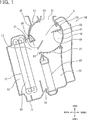
1 ist eine Querschnittsansicht, welche eine Fahrzeugklimaanlage gemäß einer ersten Ausführungsform der vorliegenden Erfindung zeigt. 1 FIG. 10 is a cross-sectional view showing a vehicle air conditioner according to a first embodiment of the present invention. FIG.
2 ist eine Querschnittsansicht, welche einen Teil von der Fahrzeugklimaanlage gemäß der ersten Ausführungsform zeigt. 2 FIG. 10 is a cross-sectional view showing a part of the vehicle air conditioner according to the first embodiment. FIG.
3 ist eine Querschnittsansicht, welche eine Position von einer Drehklappe in einem Frontmodus gemäß der ersten Ausführungsform zeigt. 3 FIG. 15 is a cross-sectional view showing a position of a rotary door in a front mode according to the first embodiment. FIG.
4 ist eine Querschnittsansicht, welche eine Position von der Drehklappe in einem Zwei-Level-Modus gemäß der ersten Ausführungsform zeigt. 4 FIG. 15 is a cross-sectional view showing a position of the rotary door in a two-level mode according to the first embodiment. FIG.
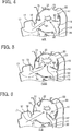
5 ist eine Querschnittsansicht, welche eine Position von der Drehklappe in einem Fußmodus gemäß der ersten Ausführungsform zeigt. 5 FIG. 12 is a cross-sectional view showing a position of the rotary door in a foot mode according to the first embodiment. FIG.
6 ist eine Querschnittsansicht, welche eine Position von der Drehklappe in einem Fuß-Defroster-Modus gemäß der ersten Ausführungsform zeigt. 6 FIG. 12 is a cross-sectional view showing a position of the rotary door in a foot defroster mode according to the first embodiment. FIG.
7 ist eine Querschnittsansicht, welche eine Position von der Drehklappe in einem Defrostermodus gemäß der ersten Ausführungsform zeigt. 7 FIG. 12 is a cross-sectional view showing a position of the rotary door in a defrosting mode according to the first embodiment. FIG.
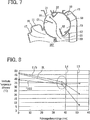
8 ist ein Diagramm, welches ein Beispiel von einer Beziehung zwischen einer Führungselementlänge und einer vertikalen Temperaturdifferenz gemäß der ersten Ausführungsform zeigt. 8th FIG. 15 is a diagram showing an example of a relationship between a guide member length and a vertical temperature difference according to the first embodiment. FIG.
9 ist ein Diagramm, welches ein Beispiel von einer Beziehung zwischen der Führungselementlänge und einem Druckverlust gemäß der ersten Ausführungsform zeigt. 9 FIG. 12 is a diagram showing an example of a relationship between the guide member length and a pressure loss according to the first embodiment. FIG.
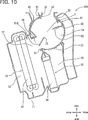
10 ist eine Querschnittsansicht, welche eine Fahrzeugklimaanlage gemäß einer zweiten Ausführungsform der vorliegenden Erfindung zeigt. 10 FIG. 10 is a cross-sectional view showing a vehicle air conditioner according to a second embodiment of the present invention. FIG.
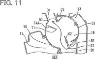
11 ist eine Querschnittsansicht, welche eine Position von einer Drehklappe in einem Defrostermodus gemäß der zweiten Ausführungsform zeigt. 11 FIG. 12 is a cross-sectional view showing a position of a rotary door in a defrosting mode according to the second embodiment. FIG.
Ausführungsformen zur Nutzung der ErfindungEmbodiments for using the invention
Im Folgenden werden hier mehrere Ausführungsformen für ein Umsetzen der vorliegenden Erfindung mit einer Bezugnahme auf die Zeichnungen beschrieben werden. Bei den jeweiligen Ausführungsformen kann ein Teil, welcher einem Umstand entspricht, der bei einer vorherigen Ausführungsform beschrieben ist, mit den gleichen Bezugszeichen bezeichnet sein und eine redundante Erläuterung für den Teil kann weggelassen sein. Wenn lediglich ein Teil einer Ausgestaltung bei einer Ausführungsform beschrieben ist, kann eine andere vorherige Ausführungsform an die anderen Teile von der Ausgestaltung angewendet werden. Die Teile können selbst dann kombiniert werden, wenn es nicht ausdrücklich beschrieben ist, dass die Teile kombiniert werden können. Die Ausführungsformen können selbst dann teilweise kombiniert werden, wenn es nicht ausdrücklich beschrieben ist, dass die Ausführungsformen kombiniert werden können, vorausgesetzt, dass es keinen Konflikt bei der Kombination gibt.Hereinafter, several embodiments for practicing the present invention will be described with reference to the drawings. In the respective embodiments, a part corresponding to a circumstance described in a previous embodiment may be included be denoted by the same reference numerals and a redundant explanation for the part may be omitted. When only a part of a configuration is described in one embodiment, another prior embodiment may be applied to the other parts of the embodiment. The parts can be combined even if it is not expressly described that the parts can be combined. The embodiments may be partially combined even if it is not expressly described that the embodiments may be combined, provided that there is no conflict in the combination.
Erste AusführungsformFirst embodiment
Eine erste Ausführungsform der vorliegenden Erfindung wird mit einer Bezugnahme auf die 1 bis 9 beschrieben werden. Die jeweiligen Pfeile oben, unten, vorne und hinten stellen Richtungen in einem Zustand dar, in welchem sie auf einem Fahrzeug montiert ist. Eine Richtung des Fahrzeuges rechts-links (Breite) ist eine Richtung senkrecht zu einer Ebene des Papiers von der 1.A first embodiment of the present invention will be described with reference to FIGS 1 to 9 to be discribed. The respective arrows at the top, bottom, front and rear represent directions in a state in which it is mounted on a vehicle. A direction of the vehicle right-left (width) is a direction perpendicular to a plane of the paper of the 1 ,
Eine Fahrzeugklimaanlage 10 ist in etwa bei einem mittleren Teil in der Richtung des Fahrzeuges rechts-links im Innern von einem Armaturenbrett angeordnet, das an einem vorderen Teil von einer Fahrgastzelle eines Fahrzeuges positioniert ist. An der Fahrzeugklimaanlage 10 eines Fahrzeuges ist ein Gebläse (nicht gezeigt) in einem vorderen Teil des Fahrzeuges angeordnet. Das Gebläse umfasst einen Gebläselüfter, welcher einen zentrifugalen Mehrfachblattlüfter (Sirocco-Lüfter) umfasst und ausgebildet ist, um durch einen elektrischen Motor (nicht gezeigt) in Drehung angetrieben zu werden. An einer Saugseite von dem Gebläselüfter ist eine Innenluft-Außenluft-Schaltbox (nicht gezeigt) verbunden. Der Gebläselüfter saugt eine Außenluft oder eine Innenluft, welche durch die Innenluft-Außenluft-Schaltbox eingeführt wird, an und bläst die Luft in Richtung zu einem am weitesten vorne liegenden Raum von einem Klimaanlagengehäuse 11.A vehicle air conditioner 10 is disposed at a middle part in the direction of the vehicle right-left inside of a dashboard, which is positioned at a front part of a passenger compartment of a vehicle. At the vehicle air conditioner 10 of a vehicle, a blower (not shown) is arranged in a front part of the vehicle. The blower includes a blower fan which includes a centrifugal multiple fan (sirocco fan) and is adapted to be driven in rotation by an electric motor (not shown). On an intake side of the blower fan, an inside air outside air switching box (not shown) is connected. The blower fan sucks in outside air or inside air introduced through the inside air outside air switching box, and blows the air toward a frontmost room of an air conditioning case 11 ,
Das Klimaanlagengehäuse 11 umfasst darin einen Luftdurchlass 12, durch welchen eine geblasene Luft von dem Gebläselüfter strömt. Ein Verdampfer 13, welcher einem Kühl-Wärmetauscher entspricht, ist im Innern von dem Klimaanlagengehäuse 11 angeordnet.The air conditioning case 11 includes therein an air passage 12 through which blown air flows from the blower fan. An evaporator 13 , which corresponds to a cooling heat exchanger, is inside of the air conditioning case 11 arranged.
Der Verdampfer 13 ist an einer Position angeordnet, wo eine gesamte Menge von der geblasenen Luft von dem Gebläselüfter von dem vorderen Teil des Fahrzeuges zu einem hinteren Teil des Fahrzeuges hindurchgeht.The evaporator 13 is disposed at a position where a total amount of the blown air from the blower fan passes from the front part of the vehicle to a rear part of the vehicle.
Der Verdampfer 13 umfasst eine bekannte Konfiguration eines Wärmeaustausch-Kernabschnitts 14, bei welchem abgeflachte Rohre (nicht gezeigt), welche Kältemitteldurchlässe aufweisen, und gewellte Wärmeübertragungsrippen (nicht gezeigt), welche einen Wärmeübertragungsbereich erhöhen, der einer Luft ausgesetzt ist, abwechselnd in großer Anzahl gestapelt und miteinander verbunden sind. Ein Kältemittel eines niedrigen Drucks, welches durch eine Dekomprimierungseinrichtung (nicht gezeigt) von einem Kältekreislauf dekomprimiert worden ist, wird durch ein Absorbieren von Wärme in den Rohren von dem Wärmeaustausch-Kernabschnitt 14 von dem Verdampfer 13 von Luft, welche durch den Verdampfer 13 hindurchgeht, verdampft und dementsprechend wird die hindurchgehende Luft gekühlt.The evaporator 13 includes a known configuration of a heat exchange core section 14 in which flattened tubes (not shown) having refrigerant passages and corrugated heat transferring fins (not shown) which increase a heat transfer area exposed to air are alternately stacked and connected in large numbers. A low pressure refrigerant decompressed by a refrigeration cycle by a decompressing means (not shown) is obtained by absorbing heat in the tubes from the heat exchanging core portion 14 from the evaporator 13 of air passing through the evaporator 13 goes through, evaporates and accordingly the passing air is cooled.
Bei dem Klimaanlagengehäuse 11 ist ein Heißwasserheizkern 15, welcher einem Heizwärmetauscher entspricht, an einer windabgewandten Seite (Rückseite des Fahrzeuges) von dem Verdampfer 13 angeordnet. Der Heizkern 15 heizt Luft durch Verwenden von heißem Wasser von einem Fahrzeugmotor (nicht gezeigt) als eine Wärmequelle auf. Der Heizkern 15 umfasst einen bekannten Wärmeaustauschkernabschnitt 16, in welchem abgeflachte Rohre (nicht gezeigt), welche Heißwasserdurchlässe aufweisen, und gewellte Wärmeübertragungsrippen (nicht gezeigt), welche einen Wärmeübertragungsbereich erhöhen, der einer Luft ausgesetzt ist, abwechselnd in großer Anzahl in der Richtung rechts-links des Fahrzeuges gestapelt sind.In the air conditioning case 11 is a hot water heater core 15 , which corresponds to a heating heat exchanger, on a leeward side (back of the vehicle) from the evaporator 13 arranged. The heating core 15 heats air by using hot water from a vehicle engine (not shown) as a heat source. The heating core 15 includes a known heat exchange core section 16 in which flattened tubes (not shown) having hot water passages and corrugated heat transfer fins (not shown) which increase a heat transfer area exposed to air are stacked alternately in large numbers in the right-left direction of the vehicle.
Der Heizkern 15 ist in der Höhenabmessung viel kleiner als der Verdampfer 13 und somit ist ein Kühlluftdurchlass 17, durch welchen die kalte Luft zu einem Umgehen des Heizkerns 15 strömt, zwischen einem oberen Endteil von dem Heizkern 15 und einem oberen Oberflächenteil von dem Klimaanlagengehäuse 11 vorgesehen. Ein stromabwärts liegender Teil von dem Kühlluftdurchlass 17 ist ein Kühllufteinströmabschnitt 18, durch welchen die kalte Luft in einen Mischraum 19 strömt.The heating core 15 is much smaller in height than the evaporator 13 and thus is a cooling air passage 17 through which the cold air to bypass the heater core 15 flows between an upper end part of the heater core 15 and an upper surface part of the air conditioning case 11 intended. A downstream part of the cooling air passage 17 is a cooling air inflow section 18 through which the cold air enters a mixing room 19 flows.
Auf der anderen Seite ist in dem Klimaanlagengehäuse 11 ein Warmluftdurchlass 20 an einer stromabwärtigen Seite von dem Heizkern 15 in einer Luftströmung vorgesehen und erstreckt sich von unmittelbar stromabwärts von dem Heizkern 15 nach oben. Ein stromabwärtiger Teil von dem Warmluftdurchlass 20 ist ein Warmlufteinströmabschnitt 21, durch welchen die warme Luft in den Mischraum 19 strömt. Der Mischraum 19 ist somit an stromabwärtigen Seiten von dem Kühlluftdurchlass 17 und dem Warmluftdurchlass 20 vorgesehen und die kalte Luft von dem Kühlluftdurchlass 17 und die warme Luft von dem Warmluftdurchlass 20 treffen bei einem Sichkreuzen miteinander in dem Mischraum 19 derart zusammen, dass die kalte Luft und die warme Luft miteinander gemischt werden.On the other side is in the air conditioning case 11 a warm air passage 20 on a downstream side of the heater core 15 provided in an air flow and extending from immediately downstream of the heater core 15 up. A downstream part of the warm air passage 20 is a warm air inflow section 21 through which the warm air enters the mixing room 19 flows. The mixing room 19 is thus at downstream sides of the cooling air passage 17 and the warm air passage 20 provided and the cold air from the cooling air passage 17 and the warm air from the warm air passage 20 meet each other in a crossover in the mixing room 19 in such a way that the cold air and the warm air are mixed together.
An dem oberen Oberflächenteil von dem Klimaanlagengehäuse 11 ist ein Defrosterluftausströmdurchlass 31 an einer vorderen Position des Fahrzeuges geöffnet. Der Defrosterluftausströmdurchlass 31 ist ein Durchlass, in welchem eine im Hinblick auf die in der Temperatur geregelte Luft von dem Mischraum 19 strömt und ist mit einem Defrosterluftauslass durch eine nicht gezeigte Defrosterleitung verbunden. Eine Luft wird in Richtung zu einer inneren Oberfläche von einer vorderen Fensterscheibe von dem Fahrzeug von dem Defrosterluftauslass geblasen.At the upper surface part of the air conditioning case 11 is a defroster air discharge passage 31 opened at a front position of the vehicle. The defroster air discharge passage 31 is a passage in which one in terms of temperature-controlled air from the mixing chamber 19 flows and is connected to a Defrosterluftauslass by a defroster, not shown. An air is blown toward an inner surface of a front windowpane of the vehicle from the defroster air outlet.
An dem oberen Oberflächenteil von dem Klimaanlagengehäuse 11 öffnet sich ein Frontluftausströmdurchlass 32 an einer von dem Fahrzeug nach hinten liegenden Position von dem Defrosterluftausströmdurchlass 31. Der Frontluftausströmdurchlass 32 ist auch ein Durchlass, in welchen eine im Hinblick auf die in der Temperatur geregelte Luft von dem Mischraum 19 strömt. Der Frontluftausströmdurchlass 32 ist mit einem Frontluftauslass durch eine nicht gezeigte Frontleitung verbunden. Eine Luft wird in Richtung zu dem Kopf-bis-Brust-Teil von einem Insassen in der Fahrgastzelle des Fahrzeuges von dem Frontluftauslass geblasen.At the upper surface part of the air conditioning case 11 opens a Frontluftausströmdurchlass 32 at a rearward position of the vehicle from the defroster air discharge passage 31 , The front air outlet passage 32 is also a passage in which one in terms of temperature-controlled air from the mixing chamber 19 flows. The front air outlet passage 32 is connected to a front air outlet through a front pipe, not shown. An air is blown toward the head-to-chest part by an occupant in the vehicle compartment of the vehicle from the front air outlet.
An dem oberen Oberflächenteil von dem Klimaanlagengehäuse 11 ist ein Fußluftausströmdurchlass 33 an einer nach hinten gehenden Position des Fahrzeuges von dem Frontluftausströmdurchlass 32 geöffnet. Der Fußluftausströmdurchlass 33 ist ebenso ein Durchlass, in welchem die in der Temperatur geregelte Luft von dem Mischraum 19 strömt. Eine stromabwärtige Seile von dem Fußluftausströmdurchlass 33 ist mit einem Fußluftauslass durch eine nicht gezeigte Fußleitung verbunden. Eine Luft wird in Richtung zu einem Fußbereich von den Insassen von dem Fußluftauslass her geblasen.At the upper surface part of the air conditioning case 11 is a Fußluftausströmdurchlass 33 at a rearward position of the vehicle from the front air exhaust passage 32 open. The Fußluftausströmdurchlass 33 is also a passage in which the temperature controlled air from the mixing chamber 19 flows. A downstream ropes from the foot air discharge passage 33 is connected to a Fußluftauslass by a foot line, not shown. Air is blown toward a foot area from the occupants of the foot air outlet.
In dem Mischraum 19 ist eine Drehklappe 41 angeordnet. Die jeweiligen Luftausströmdurchlässe 31 bis 33 und die jeweiligen Einströmabschnitte 18 und 21 sind an einer äußeren Seite von der Drehklappe 41 in einer radialen Richtung positioniert. Die Drehklappe 41 ist getragen, um in dem Klimaanlagengehäuse 11 drehbar (winkelbezogen verstellbar) zu sein. Die Drehklappe 41 ist aus zum Beispiel einem Harzmaterial hergestellt und umfasst einen Klappenplattenabschnitt 42, welcher ein bogenförmiger Wandabschnitt ist, welcher in einem vorherbestimmten Abstand von der Drehachse (Antriebsachse) L angeordnet ist. Der Klappenplattenabschnitt 42 von der Drehklappe 41 dreht sich um die Drehachse L. Der Klappenplattenabschnitt 42 umfasst drei Öffnungsteile 51 bis 53. Die drei Öffnungsteile 51 bis 53 von dem Klappenplattenabschnitt 42 sind Abschnitte für ein Öffnen oder ein Schließen der jeweiligen Luftausströmdurchlässe 31 bis 33 und der jeweiligen Einströmabschnitte 18 und 21. Zum Beispiel verursachen Verstellungen von dem ersten Öffnungsteil 51 und dem dritten Öffnungsteil 53 aufgrund der Drehung der Drehklappe 41 eine Kommunikation mit den drei Luftausströmdurchlässen 31 bis 33 und eine Regelung von ihren Durchlassöffnungsbereichen. Des Weiteren bringt zum Beispiel eine Verstellung von dem ersten Öffnungsteil 51 aufgrund der Drehung der Drehklappe 41 ein Inneres von der Drehklappe 41 dazu, mit dem Kühllufteinströmabschnitt 18 in Kommunikation zu gelangen. Wenn der Kühllufteinströmabschnitt 18 in den geöffneten Zustand gelangt, strömt die kalte Luft zu dem Inneren von der Drehklappe 41 in der radialen Richtung bin. Auf ähnliche Art und Weise bringt zum Beispiel eine Verstellung des zweiten Öffnungsteils 52 aufgrund der Drehung der Drehklappe 41 das Innere der Drehklappe 41 dazu, mit dem Warmlufteinströmabschnitt 21 in Kommunikation zu gelangen. Wenn der Warmlufteinströmabschnitt 21 in den offenen Zustand gelangt, strömt die warme Luft zu dem Inneren von der Drehklappe 41 in der radialen Richtung hin.In the mixing room 19 is a rotary valve 41 arranged. The respective Luftausströmdurchlässe 31 to 33 and the respective inflow sections 18 and 21 are on an outer side of the rotary damper 41 positioned in a radial direction. The rotary flap 41 is carried to the air conditioning case 11 rotatable (adjustable angle) to be. The rotary flap 41 is made of, for example, a resin material and includes a flap plate portion 42 which is an arcuate wall portion which is arranged at a predetermined distance from the rotation axis (drive axis) L. The flap plate section 42 from the rotary valve 41 rotates about the axis of rotation L. The flap plate section 42 includes three opening parts 51 to 53 , The three opening parts 51 to 53 from the flapper plate section 42 are sections for opening or closing the respective Luftausströmdurchlässe 31 to 33 and the respective inflow sections 18 and 21 , For example, adjustments cause from the first opening part 51 and the third opening part 53 due to the rotation of the damper 41 a communication with the three Luftausströmdurchlässen 31 to 33 and a regulation of their passage opening areas. Furthermore, for example, brings an adjustment of the first opening part 51 due to the rotation of the damper 41 a heart from the damper 41 to, with the Kühllufteinströmabschnitt 18 to get in communication. When the cooling air inflow section 18 enters the open state, the cold air flows to the interior of the rotary valve 41 in the radial direction. In a similar way, for example, brings an adjustment of the second opening part 52 due to the rotation of the damper 41 the interior of the butterfly valve 41 to do so, with the warm air inflow section 21 to get in communication. When the warm air inflow section 21 enters the open state, the warm air flows to the interior of the rotary valve 41 in the radial direction.
In anderen Worten sind der Defrosterluftausströmdurchlass 31, der Frontluftausströmdurchlass 32, der Fußluftausströmdurchlass 33, der Kühllufteinströmabschnitt 18 und der Warmlufteinströmabschnitt 21 durch die Drehklappe 41 geöffnet oder geschlossen. Die Drehklappe 41 stellt einen Luftauslassmodus bereit, bei welchem einer oder mehrere von dem Defrosterluftausströmdurchlass 31, dem Frontluftausströmdurchlass 32 und dem Fußluftausströmdurchlass 33 in Übereinstimmung mit einer drehbezogenen Stoppposition von der Drehklappe 41 geöffnet ist. Die Drehklappe 41 funktioniert somit als eine sogenannte Luftauslassmodusklappe, welche den Luftauslassmodus schaltet. Die Drehklappe 41 regelt ein Offen-geschlossen-Verhältnis von dem Kühllufteinströmabschnitt 18 und dem Warmlufteinströmabschnitt 21 und steuert ein Strömungsratenverhältnis von der warmen Luft und von der kalten Luft. Die Drehklappe 41 funktioniert somit ebenso als eine sogenannte Luftmischklappe.In other words, the defroster air discharge passage 31 , the front air exhaust passage 32 , the foot air outlet passage 33 , the cooling air inflow section 18 and the warm air inflow section 21 through the rotary flap 41 open or closed. The rotary flap 41 provides an air outlet mode in which one or more of the defroster air discharge passage 31 , the front air discharge passage 32 and the Fußluftausströmdurchlass 33 in accordance with a rotational stop position of the rotary door 41 is open. The rotary flap 41 thus functions as a so-called air outlet mode door which switches the air outlet mode. The rotary flap 41 controls an open-close relationship of the cooling air inflow section 18 and the warm air inflow section 21 and controls a flow rate ratio of the warm air and the cold air. The rotary flap 41 thus works as well as a so-called air mixing valve.
Ein Kühlluftleitelement 61 und ein Warmluftleitelement 62 sind an einer radial inneren Seite von der Drehklappe 41 vorgesehen. Das Kühlluftleitelement 61 ist ein Element zum Leiten der kalten Luft von dem Kühllufteinströmabschnitt 18 zu einer Mitte von der Drehklappe 41 bin. Das Warmluftleitelement 62 ist ein Element zum Leiten der warmen Luft von dem Warmlufteinströmabscbnitt 21 zu der Mitte von der Drehklappe 41 hin. Das Kühlluftleitelement 61 und das Warmluftleitelement 62 sind durch ein integrales Gießen mit der Drehklappe 41 derart ausgebildet, um sich integral mit der Drehklappe 41 zu drehen.A cooling air guide 61 and a hot air guide 62 are on a radially inner side of the rotary valve 41 intended. The cooling air guide 61 is an element for conducting the cold air of the Kühllufteinströmabschnitt 18 to a middle of the rotary valve 41 am. The hot air control element 62 is an element for guiding the warm air from the warm air inflow section 21 to the middle of the damper 41 out. The cooling air guide 61 and the hot air guide 62 are by an integral casting with the rotary damper 41 designed to be integral with the rotary valve 41 to turn.
Das Kühlluftleitelement 61 ist mit einem Wandabschnitt verbunden, welcher an einer Position angeordnet ist, die von einer Papierebene der 2 in ihrer Dickenrichtung (Richtung rechts-links des Fahrzeuges) versetzt ist. Ein Randteil von dem Warmluftleitelement 62 ist mit dem Klappenplattenabschnitt 42 verbunden. Das Kühlluftleitelement 61 und das Warmluftleitelement 62 erstrecken sich jedes in Richtung zu der Mitte von der Drehklappe 41 von einem Randteil zu dem anderen Randteil bin. Die Randteile von dem Kühlluftleitelement 61 und dem Warmluftleitelement 62, welche zu dem mittleren Teil von der Drehklappe 41 hin weisen, sind voneinander in einem Abstand vorgesehen. Die Mitte von der Drehklappe 41 ist eine rotationsbezogene Mitte von der Drehklappe 41. Eine Länge L1 von dem Kühlluftleitelement 61 und eine Länge L2 von dem Warmluftleitelement 62 sind zueinander gleich. Ein Abstand L3 zwischen dem anderen Randteil von dem Kühlluftleitelement 61 und dem anderen Randteil von dem Warmluftleitelement 62 ist größer als eine Durchlassbreite L4 von dem Frontluftausströmdurchlass 32 in einer umfänglichen Richtung und einer Durchlassbreite L5 von dem Fußluftausströmdurchlass 33 in der umfänglichen Richtung.The cooling air guide 61 is connected to a wall portion which is disposed at a position of a paper plane of the 2 in their thickness direction (right-left direction of the vehicle) is offset. An edge part of the hot air guide 62 is with the flap plate section 42 connected. The cooling air guide 61 and the hot air guide 62 each extend towards the center of the damper 41 from one edge part to the other edge part. The edge parts of the Kühlluftleitelement 61 and the hot air guide 62 leading to the middle part of the rotary valve 41 point, are provided from each other at a distance. The middle of the rotary valve 41 is a rotation center of the damper 41 , A length L1 of the Kühlluftleitelement 61 and a length L2 from the hot air guide 62 are equal to each other. A distance L3 between the other edge part of the Kühlluftleitelement 61 and the other edge part of the hot air guide 62 is larger than a passage width L4 from the front air exhaust passage 32 in a circumferential direction and a passage width L5 from the Fußluftausströmdurchlass 33 in the circumferential direction.
Die Fahrzeugklimaanlage 10, welche die oben beschriebene Konfiguration aufweist, umfasst zum Beispiel eine elektronische Steuereinrichtung (nicht gezeigt), an welche Betriebssignale von verschiedenen Betriebselementen, welche in einem Klimaanlagenbetriebsbrett (nicht gezeigt) vorgesehen sind, und Sensorsignale von verschiedenen Sensoren für eine Klimaanlagensteuerung eingegeben werden. Positionen von den jeweiligen Klappen werden durch Ausgangssignale von der Steuereinrichtung gesteuert.The vehicle air conditioner 10 having the above-described configuration includes, for example, an electronic control device (not shown) to which operating signals from various operation elements provided in an air conditioning operation board (not shown) and sensor signals from various sensors for an air conditioner control are input. Positions of the respective flaps are controlled by output signals from the controller.
Als Nächstes werden Bewegungen von der Drehklappe 41 beschrieben werden. Die 3 bis 7 sind Darstellungen, welche Positionen von der Drehklappe 41 in fünf Luftauslassmodi darstellen. Gemäß der Fahrzeugklimaanlage 10 der vorliegenden Ausführungsform umfassen, wie es in der 3 bis 7 gezeigt ist, die Luftauslassmodi zum Beispiel einen Frontmodus (FRONT), einen Zwei-Level-Modus (B/L), einen Fußmodus (FUSS), einen Fuß-Defroster-Modus (F/D) und einen Defrostermodus (DEF). Die Tabelle 1 zeigt Öffnungs-Schließ-Zustände von den jeweiligen Luftausströmdurchlässen 31 bis 33 und den jeweiligen Einströmabschnitten 18 und 21 in jedem Modus. In der Tabelle I ist ein offener Zustand durch O dargestellt und ein geschlossener Zustand ist durch x dargestellt. Tabelle 1 Frontluftauslassteil Fußluftauslassteil Defrosterluftauslassteil Kühllufteinströmteil Warmlufteinströmteil
FRONT O x x O x
B/L O O x O O
FUSS x O x O O
F/D x O O O O
DEF x x O x O
Next will be movements from the damper 41 to be discribed. The 3 to 7 are representations of what positions of the rotary valve 41 in five air outlet modes. According to the vehicle air conditioner 10 of the present embodiment, as shown in FIG 3 to 7 For example, the air outlet modes are shown as FRONT mode, B-L (two-level mode), FOOT mode (foot), foot defroster mode (F / D), and defrost mode (DEF). Table 1 shows opening-closing states of the respective air exhaust passages 31 to 33 and the respective inflow sections 18 and 21 in every mode. In Table I, an open state is represented by O, and a closed state is represented by x. Table 1 Frontluftauslassteil Fußluftauslassteil Defrosterluftauslassteil Kühllufteinströmteil Warmlufteinströmteil
FRONT O x x O x
B / L O O x O O
FOOT x O x O O
F / D x O O O O
DEF x x O x O
Als erstes wird unter einer Bezugnahme auf die 3 der Frontmodus beschrieben werden. Der Frontmodus ist ein Modus, bei welchem eine klimatisierte Luft (Klimatisierungsluft) hauptsächlich zu einem oberen Teil von einem Insassen geblasen wird. Bei dem Frontmodus ist die Drehklappe 41 an einer Position angeordnet, bei welcher der Frontluftausströmdurchlass 32 in dem offenen Zustand ist, der Defrosterluftausströmdurchlass 31 in dem geschlossenen Zustand ist, der Kühllufteinströmabschnitt 18 in dem offenen Zustand ist und der Warmlufteinströmabschnitt 21 in dem geschlossenen Zustand ist. Dementsprechend wird die kalte Luft als die klimatisierte Luft in die Fahrgastzelle des Fahrzeuges von dem Mischraum 19 durch den Frontluftausströmdurchlass 32 geblasen. In dem Frontmodus ist daher die Drehklappe 41 an einer maximalen Kühlposition angeordnet, bei welcher der Warmluftdurchlass 20, welcher durch den Wärmeaustausch-Kernabschnitt 16 von dem Heizkern 15 hindurchgeht, vollständig geschlossen ist, während der Kühlluftdurchlass 17 vollständig offen ist.First, with reference to the 3 the front mode are described. The front mode is a mode in which conditioned air (air conditioning air) is mainly blown to an upper part of an occupant. In the front mode, the damper is 41 disposed at a position where the front air discharge passage 32 in the open state, the defroster air discharge passage 31 in the closed state, the cooling air inflow portion 18 in the open state and the warm air inflow section 21 in the closed state. Accordingly, the cold air as the conditioned air into the passenger compartment of the vehicle from the mixing room 19 through the front air discharge passage 32 blown. In front mode, therefore, is the damper 41 arranged at a maximum cooling position, wherein the hot air passage 20 passing through the heat exchange core section 16 from the heater core 15 passes through, is completely closed, while the cooling air passage 17 completely open.
In dem Frontmodus ist der Kühllufteinströmabschnitt 18 in dem offenen Zustand. Das Kühlluftleitelement 61 leitet somit die kalte Luft in Richtung zu der Mitte von der Drehklappe 41. Die kalte Luft strömt direkt in Richtung zu dem Frontluftausströmdurchlass 32, welcher an einer Position gegenüberliegend zu dem Kühllufteinströmabschnitt 18 angeordnet ist. Ein Strömungswiderstand von der kalten Luft kann daher durch das Kühlluftleitelement 61 reduziert werden.In the front mode, the cooling air inflow section 18 in the open state. The cooling air guide 61 thus directs the cold air towards the center of the rotary valve 41 , The cold air flows directly toward the front air exhaust passage 32 , which at a position opposite to the Kühllufteinströmabschnitt 18 is arranged. A flow resistance of the cold air can therefore by the Kühlluftleitelement 61 be reduced.
Als Nächstes wird unter einer Bezugnahme auf die 4 der Zwei-Level-Modus beschrieben werden. Der Zwei-Level-Modus ist ein Modus, bei welchem eine klimatisierte Luft zu einem oberen Teil von einem Insassen und einem Fußbereich von dem Insassen geblasen wird. Bei dem Zwei-Level-Modus ist die Drehklappe 41 an einer Position angeordnet, bei welcher der Frontluftausströmdurchlass 32 und der Fußluftausströmdurchlass 33 in dem offenen Zustand sind, der Defrosterluftausströmdurchlass 31 in dem geschlossenen Zustand ist und der Kühllufteinströmabschnitt 18 und der Warmlufteinströmabschnitt 21 in dem offenen Zustand sind. Dementsprechend wird die klimatisierte Luft in die Fahrgastzelle des Fahrzeuges von dem Mischraum 19 durch den Frontluftausströmdurchlass 32 und den Fußluftausströmdurchlass 33 geblasen. In dem Zwei-Level-Modus ist daher die Drehklappe 41 an einer Position angeordnet, bei welcher sowohl der Warmluftdurchlass 20 als auch der Kühlluftdurchlass 17 offen sind.Next, with reference to the 4 the two-level mode will be described. The two-level mode is a mode in which conditioned air is blown to an upper part of an occupant and a foot area of the occupant. In the two-level mode, the damper is 41 disposed at a position where the front air discharge passage 32 and the Fußluftausströmdurchlass 33 in the open state, the defroster air discharge passage 31 in the closed state and the Kühllufteinströmabschnitt 18 and the warm air inflow section 21 in the open state. Accordingly, the conditioned air is introduced into the passenger compartment of the vehicle from the mixing room 19 through the front air discharge passage 32 and the Fußluftausströmdurchlass 33 blown. In the two-level mode, therefore, the damper is 41 arranged at a position at which both the warm air passage 20 as well as the cooling air passage 17 are open.
In dem Zwei-Level-Modus ist eine Position von dem Randteil von dem Kühlluftleitelement 61 angrenzend zu dem Kühllufteinströmabschnitt 18 in einem unteren Randteil von der Öffnung von dem Kühllufteinströmabschnitt 18 angeordnet. Das Kühlluftleitelement 61 ist dementsprechend in der Lage zu einem Leiten der kalten Luft, welche von dem Kühllufteinströmabschnitt 18 her strömt, in Richtung zu der Mitte von der Drehklappe 41.In the two-level mode, a position is from the edge part of the cooling air guide 61 adjacent to the cooling air inflow section 18 in a lower edge portion of the opening of the cooling air inflow portion 18 arranged. The cooling air guide 61 Accordingly, it is capable of passing the cold air coming from the cooling air inflow section 18 flows towards the center of the damper 41 ,
Als Nächstes wird unter einer Bezugnahme auf die 5 der Fußmodus beschrieben werden. Der Fußmodus ist ein Modus, bei welchem eine klimatisierte Luft zu einem Fußbereich von einem Insassen geblasen wird. In dem Fußmodus ist die Drehklappe 41 an einer Position angeordnet, wo der Frontluftausströmdurchlass 32 und der Defrosterluftausströmdurchlass 31 in einem geschlossenen Zustand sind, der Fußluftausströmdurchlass 33 in dem offenen Zustand ist und der Kühllufteinströmabschnitt 18 und der Warmlufteinströmabschnitt 21 in dem offenen Zustand sind. Die klimatisierte Luft wird dementsprechend in die Fahrgastzelle des Fahrzeuges von dem Mischraum 19 her durch den Fußluftausströmdurchlass 33 geblasen. In dem Fußmodus ist des Weiteren die Drehklappe 41 an einer Position angeordnet, wo sowohl der Warmluftdurchlass 20 als auch der Kühlluftdurchlass 17 offen sind. Eine Öffnung von dem Warmlufteinströmabschnitt 21 ist breiter und eine Öffnung von dem Kühllufteinströmabschnitt 18 ist enger als diejenigen in dem Zwei-Level-Modus.Next, with reference to the 5 the foot mode will be described. The foot mode is a mode in which conditioned air is blown to a foot area by an occupant. In foot mode is the damper 41 disposed at a position where the front air discharge passage 32 and the defroster air discharge passage 31 in a closed state, the Fußluftausströmdurchlass 33 in the open state and the Kühllufteinströmabschnitt 18 and the warm air inflow section 21 in the open state. The conditioned air is accordingly in the passenger compartment of the vehicle from the mixing room 19 through the Fußluftausströmdurchlass 33 blown. In the foot mode is also the rotary valve 41 arranged at a position where both the warm air passage 20 as well as the cooling air passage 17 are open. An opening from the warm air inflow section 21 is wider and an opening from the Kühllufteinströmabschnitt 18 is narrower than those in the two-level mode.
In dem Fußmodus ist eine Position von dem Randteil von dem Kühlluftleitelement 61 angrenzend zu dem Kühllufteinströmabschnitt 18 in einem oberen Randteil von der Öffnung von dem Kühllufteinströmabschnitt 18 angeordnet. Dementsprechend ist das Kühlluftleitelement 61 zu einem Leiten der kalten Luft, welche von dem Kühllufteinströmabschnitt 18 her strömt, in Richtung zu der Mitte von der Drehklappe 41 in der Lage. Des Weiteren ist eine Position von dem Randteil von dem Warmluftleitelement 62 angrenzend zu dem Warmlufteinströmabschnitt 21 in einem oberen Randteil von einer Öffnung von dem Warmlufteinströmabschnitt 21 angeordnet. Dementsprechend ist das Warmluftleitelement 62 zu einem Leiten der warmen Luft, welche von dem Warmlufteinströmabschnitt 21 her strömt, in Richtung zu der Mitte von der Drehklappe 41 in der Lage.In the foot mode, a position is from the edge part of the cooling air guide 61 adjacent to the cooling air inflow section 18 in an upper edge portion of the opening of the cooling air inflow portion 18 arranged. Accordingly, the Kühlluftleitelement 61 to directing the cold air coming from the cooling air inflow section 18 flows towards the center of the damper 41 in a position. Furthermore, a position of the edge part of the hot air guide is 62 adjacent to the warm air inflow section 21 in an upper edge portion of an opening of the warm air inflow portion 21 arranged. Accordingly, the hot air guide element 62 to direct the warm air coming from the warm air inflow section 21 flows towards the center of the damper 41 in a position.
Als Nächstes wird unter einer Bezugnahme auf die 6 der Fuß-Defroster-Modus beschrieben werden. Der Fuß-Defroster-Modus ist ein Modus, bei welchem eine klimatisierte Luft zu einer vorderen Fensterscheibe und einem Fußbereich von einem Insassen geblasen wird. In dem Fuß-Defroster-Modus ist die Drehklappe 41 an einer Position angeordnet, wo der Frontluftausströmdurchlass 32 in dem geschlossenen Zustand ist, der Fußluftausströmdurchlass 33 und der Defrosterluftausströmdurchlass 31 in dem offenen Zustand sind und der Kühllufteinströmabschnitt 18 und der Warmlufteinströmabschnitt 21 in dem offenen Zustand sind. Die klimatisierte Luft wird dementsprechend in die Fahrgastzelle des Fahrzeuges von dem Mischraum 19 her durch den Defrosterluftausströmdurchlass 31 und den Fußluftausströmdurchlass 33 geblasen. In dem Fuß-Defroster-Modus ist des Weiteren die Drehklappe 41 an einer Position angeordnet, wo sowohl der Warmluftdurchlass 20 als auch der Kühlluftdurchlass 17 offen sind. Eine Öffnung von dem Warmlufteinströmabschnitt 21 ist breiter und eine Öffnung von dem Kühllufteinströmabschnitt 18 ist enger als diejenigen bei dem Fußmodus.Next, with reference to the 6 the foot defroster mode will be described. The foot defroster mode is a mode in which conditioned air is blown toward a front window glass and a foot area by an occupant. In the foot defroster mode is the damper 41 disposed at a position where the front air discharge passage 32 in the closed state, the Fußluftausströmdurchlass 33 and the defroster air discharge passage 31 in the open state and the Kühllufteinströmabschnitt 18 and the warm air inflow section 21 in the open state. The conditioned air is accordingly in the passenger compartment of the vehicle from the mixing room 19 through the defroster air discharge passage 31 and the Fußluftausströmdurchlass 33 blown. In the foot defroster mode is also the rotary damper 41 arranged at a position where both the warm air passage 20 as well as the cooling air passage 17 are open. An opening from the warm air inflow section 21 is wider and an opening from the Kühllufteinströmabschnitt 18 is narrower than those in the foot mode.
Dementsprechend bringt in dem Fußmodus, dem Fuß-Defroster-Modus und dem Zwei-Level-Modus der erste Öffnungsteil 51 den Kühllufteinströmabschnitt 18 in den offenen Zustand und der zweite Öffnungsteil 52 bringt den Warmlufteinströmabschnitt 21 in den offenen Zustand. Das Kühlluftleitelement 61 ist positioniert, um die kalte Luft in Richtung zu der Mitte von der Drehklappe 41 bin zu leiten, und das Warmmluftleitelement 62 ist positioniert, um die warme Luft in Richtung zu der Mitte von der Drehklappe 41 hin zu leiten. Die kalte Luft und die warme Luft stoßen daher miteinander an der Mitte von der Drehklappe 41 zusammen, wie es in den 4 bis 6 gezeigt ist, und die kalte Luft und die warme Luft können miteinander gemischt werden. In anderen Worten können in dem Fußmodus, dem Fuß-Defroster-Modus und in dem Zwei-Level-Modus die kalte Luft und die warme Luft zueinander gegenüberliegend gebracht werden und ein Durchmischen der Luftanteile kann somit befördert werden.Accordingly, in the foot mode, the foot defroster mode and the two-level mode, the first opening part brings 51 the cooling air inflow section 18 in the open state and the second opening part 52 brings the warm air inflow section 21 in the open state. The cooling air guide 61 is positioned to move the cold air towards the center of the damper 41 I am to guide, and the Warmmluftleitelement 62 is positioned to move the warm air towards the center of the damper 41 to lead. The cold air and the warm air therefore collide with each other at the center of the rotary valve 41 together, as in the 4 to 6 is shown, and the cold air and the warm air can be mixed with each other. In other words, in the foot mode, the foot defroster mode and in the two-level mode, the cold Air and the warm air can be brought opposite to each other and a mixing of air fractions can thus be promoted.
Als Nächstes wird der Defrostermodus unter einer Bezugnahme auf die 7 beschrieben werden. Der Defrostermodus ist ein Modus, in welchem die klimatisierte Luft zu der vorderen Fensterscheibe hin geblasen wird. In dem Defrostermodus ist die Drehklappe 41 an einer Position angeordnet, wo der Frontluftausströmdurchlass 32 und der Fußluftausströmdurchlass 33 in dem geschlossenen Zustand sind, der Defrosterluftausströmdurchlass 31 in dem offenen Zustand ist, der Kühllufteinströmabschnitt 18 in dem geschlossenen Zustand ist und der Warmlufteinströmabschnitt 21 in dem offenen Zustand ist. Dementsprechend wird die klimatisierte Luft in die Fahrgastzelle des Fahrzeuges von dem Mischraum 19 her durch den Defrosterluftausströmdurchlass 31 geblasen. Des Weiteren ist in dem Defrostermodus die Drehklappe 41 an einer Position eines maximalen Heizen angeordnet, bei welcher der Warmluftdurchlass 20, welcher durch den Wärmeaustausch-Kernabschnitt 16 von dem Heizkern 15 hindurchgeht, vollständig offen ist, während der Kühlluftdurchlass 17 vollständig geschlossen ist.Next, the defrost mode will be referred to with reference to FIG 7 to be discribed. The defrost mode is a mode in which the conditioned air is blown toward the front window glass. In defrost mode is the damper 41 disposed at a position where the front air discharge passage 32 and the Fußluftausströmdurchlass 33 in the closed state, the defroster air discharge passage 31 in the open state, the cooling air inflow portion 18 in the closed state and the warm air inflow section 21 in the open state. Accordingly, the conditioned air is introduced into the passenger compartment of the vehicle from the mixing room 19 through the defroster air discharge passage 31 blown. Furthermore, in the defrost mode, the rotary damper 41 arranged at a position of maximum heating, wherein the hot air passage 20 passing through the heat exchange core section 16 from the heater core 15 passes through, is fully open, during the cooling air passage 17 is completely closed.
Als Nächstes werden Wirkungen von dem Kühlluftleitelement 61 und dem Warmluftleitelement 62 unter einer Bezugnahme auf die 8 und die 9 beschrieben werden. Jede horizontale Achse der 8 und der 9 stellt die Längen L1 und L2 des Leitelements dar. Die Frontdurchlassbreite L4 beträgt 40 mm und die Fußdurchlassbreite L5 beträgt 50 mm in diesem Fall. Ein Durchmesser von der Drehklappe 41 beträgt 125 mm.Next, effects will be from the cooling air guide 61 and the hot air guide 62 with reference to the 8th and the 9 to be discribed. Each horizontal axis of the 8th and the 9 represents the lengths L1 and L2 of the baffle. The front passage width L4 is 40 mm, and the foot passage width L5 is 50 mm in this case. A diameter of the rotary valve 41 is 125 mm.
Wie es oben beschrieben ist, sind die Länge L1 von dem Kühlluftleitelement 61 und die Länge L2 von dem Warmluftleitelement 62 ausgebildet, um zueinander gleich zu sein (L1 = L2). Der Abstand L3 zwischen den Leitelementen ist ausgebildet, größer zu sein als die Frontdurchlassbreite L4 und die Fußdurchlassbreite L5 (L3 > L4, L5). Die Gründe für die abmessungsbezogene Ausgestaltung werden beschrieben werden.As described above, the length L1 of the Kühlluftleitelement 61 and the length L2 of the hot air guide 62 designed to be equal to each other (L1 = L2). The distance L3 between the vanes is designed to be larger than the front passage width L4 and the foot passage width L5 (L3> L4, L5). The reasons for the dimensional design will be described.
Wie es in der 8 gezeigt ist, nehmen, wenn die Längen L1 und L2 der Führungselemente ausgebildet sind, größer zu sein, die Mengen von der kalten Luft und der warmen Luft, welche miteinander an der Mitte zusammenstoßen, zu und dementsprechend reduziert sich eine vertikale Temperaturdifferenz. Wenn die Längen der Führungselemente 50 mm überschreiten, reduziert sich die vertikale Temperaturdifferenz innerhalb der Fahrgastzelle des Fahrzeuges drastisch, insbesondere in dem Zwei-Level-Modus. In anderen Worten werden, wenn die Länge L3 zwischen den Leitelementen größer ist als die Durchlassbreite (L4, L5), die kalte Luft und die warme Luft voneinander in dem Zwei-Level-Modus getrennt und dadurch wird die vertikale Temperaturdifferenz vergrößert.As it is in the 8th As shown, when the lengths L1 and L2 of the guide members are formed to be larger, the amounts of cold air and warm air colliding with each other at the center increase, and accordingly, a vertical temperature difference reduces. When the lengths of the guide members exceed 50 mm, the vertical temperature difference within the vehicle cabin of the vehicle drastically decreases, especially in the two-level mode. In other words, when the length L3 between the guide members is larger than the passage width (L4, L5), the cold air and the warm air are separated from each other in the two-level mode, and thereby the vertical temperature difference is increased.
Wenn jedoch die Längen der Führungselemente 40 mm von der Frontdurchlassbreite L4 überschreiten, wie es in der 9 gezeigt ist, nimmt ein Druckverlust in dem Frontmodus zu. Wenn des Weiteren die Längen der Führungselemente die 50 mm von der Fußdurchlassbreite L5 überschreiten, ist, wie es in der 9 gezeigt ist, der Druckverlust in dem Fußmodus erhöht. Basierend auf einer Beziehung zwischen einem Grad eines Mischen und des Druckverlusts fallen daher die Längen L1 und L2 der Führungselemente vorzugsweise innerhalb eines Bereichs, welcher durch eine abwechselnd lange und zweimal kurz gestrichelte Link in der 8 und 9 angegeben ist. Die Längen L1 und L2 der Führungselemente und die Länge L3 zwischen den Führungselementen weisen eine Beziehung derart auf, dass je größer die Längen L1 und L2 der Führungselemente sind, umso geringer die Länge L3 zwischen den Führungselementen ist. Wenn die Länge L3 zwischen den Führungselementen gleich zu 50 mm von der Fußdurchlassbreite ist, sind die Längen L1 und L2 der Führungselemente 37,5 mm. Dies fällt innerhalb des Bereichs, welcher durch die abwechselnd lang und zweimal kurz gestrichelte Linie der 8 und 9 angegeben ist. Daher ist, wie es oben beschrieben ist, die Länge L3 zwischen den Führungselementen auf größer eingestellt als die Frontdurchlassbreite L4 und die Fußdurchlassbreite L5 (L3 > L4, L5).However, if the lengths of the guide members exceed 40 mm from the front passage width L4 as shown in FIG 9 is shown, a pressure loss in the front mode increases. Further, when the lengths of the guide members exceed 50 mm from the foot passage width L5, as shown in FIG 9 is shown, the pressure loss increases in the foot mode. Therefore, based on a relationship between a degree of mixing and the pressure loss, the lengths L1 and L2 of the guide members preferably fall within a range indicated by an alternate long and two short dashed link in FIG 8th and 9 is specified. The lengths L1 and L2 of the guide members and the length L3 between the guide members have a relationship such that the longer the lengths L1 and L2 of the guide members, the smaller the length L3 between the guide members. When the length L3 between the guide members is equal to 50 mm from the foot passage width, the lengths L1 and L2 of the guide members are 37.5 mm. This falls within the range indicated by the alternately long and two short dashed line of 8th and 9 is specified. Therefore, as described above, the length L3 between the guide members is set larger than the front passage width L4 and the foot passage width L5 (L3> L4, L5).
Bei der vorliegenden Ausführungsform sind, wie es oben beschrieben ist, das Kühlluftleitelement 61 und das Warmluftleitelement 62 im Innern von der Drehklappe 41 vorgesehen. Jedes Führungselement 61, 62 leitet die kalte Luft oder die warme Luft in Richtung zu der Mitte von der Drehklappe 41 hin. Daher können Luftanteile, welche von dem Kühllufteinströmabschnitt 18 und dem Warmlufteinströmabschnitt 21 her in das Innere von der Drehklappe 41 strömen, dazu gebracht werden, miteinander an der Mitte von der Drehklappe 41 zusammenzustoßen. Die kalte Luft und die warme Luft werden dementsprechend miteinander an der Mitte von der Drehklappe 41 gemischt. Da die Drehklappe 41 die mehreren Öffnungsteile 51 bis 53 umfasst, ändern sich, wenn sich die Drehklappe 41 dreht, relative Positionen von diesen Öffnungsteilen 51 bis 53 zu den mehreren Luftausströmdurchlässen 31 bis 33 und dadurch werden die mehreren Luftausströmdurchlässe 31 bis 33 geöffnet oder geschlossen. Die Drehklappe 41 funktioniert daher als die sogenannte Modusklappe. Wie es oben beschrieben ist, kann, da die kalte Luft und die warme Luft miteinander im Innern von der Drehklappe 41 gemischt werden, eine Luft, welche in jedem von den Luftausströmdurchlässen 31 bis 33 von der Drehklappe 41 strömt, gemischt werden. Folglich kann die Drehklappe 41 realisiert werden, welche besser ist im Hinblick auf ein Mischen von der kalten Luft und der warmen Luft und eine Funktion als die Modusklappe aufweist.In the present embodiment, as described above, the Kühlluftleitelement 61 and the hot air guide 62 inside of the rotary valve 41 intended. Every guide element 61 . 62 directs the cold air or warm air towards the center of the damper 41 out. Therefore, portions of air coming from the cooling air inflow portion 18 and the warm air inflow section 21 into the interior of the rotary valve 41 flow, be brought to each other at the center of the rotary valve 41 colliding. The cold air and the warm air are correspondingly at the center of the rotary damper 41 mixed. Because the rotary valve 41 the several opening parts 51 to 53 includes, change when the damper 41 turns, relative positions of these opening parts 51 to 53 to the multiple air discharge passages 31 to 33 and thereby the multiple air discharge passages 31 to 33 open or closed. The rotary flap 41 therefore works as the so-called mode flap. As described above, since the cold air and the warm air can communicate with each other inside the rotary door 41 mixed, an air which in each of the Luftausströmdurchlässen 31 to 33 from the rotary valve 41 flows, be mixed. Consequently, the damper can 41 which is better in terms of mixing the cold air and the warm air and having a function as the mode door.
Des Weiteren drehen sich bei der vorliegenden Ausführungsform das Kühlluftleitelement 61 und das Warmluftleitelement 62 integral mit der Drehklappe 41. Im Vergleich zu einer getrennten Ausgestaltung können die Anzahl der Gießschritte und die Anzahl von Montageschritten reduziert werden.Furthermore, in the present embodiment, the cooling air guide rotates 61 and the hot air guide 62 integral with the rotary flap 41 , Compared to a separate embodiment, the number of casting steps and the number of assembly steps can be reduced.
Des Weiteren befindet sich gemäß der vorliegenden Ausführungsform in dem Fußmodus, in dem Fuß-Defroster-Modus und in dem Zwei-Level-Modus der Kühllufteinströmabschnitt 18 in dem offenen Zustand aufgrund des ersten Öffnungsteils 51 und der Warmlufteinströmabschnitt 21 ist in dem offenen Zustand aufgrund des zweiten Öffnungsteils 52. Das Kühlluftleitelement 61 ist außerdem positioniert, um die kalte Luft in Richtung zu der Mitte von der Drehklappe 41 hin zu leiten, und das Warmluftleitelement 62 ist positioniert, um die warme Luft in Richtung zu der Mitte von der Drehklappe 41 bin zu leiten. In dem Fußmodus, in dem Fuß-Defroster-Modus und in dem Zwei-Level-Modus können daher die kalte Luft und die warme Luft dazu gebracht werden, miteinander an der Mitte von der Drehklappe 41 zusammenzustoßen. Folglich kann die vertikale Temperaturdifferenz innerhalb der Fahrgastzelle des Fahrzeuges reduziert werden und eine Lufttemperatur kann dazu gebracht werden, sich einer eingestellten Temperatur in diesen Luftausslassmodi anzunähern.Further, according to the present embodiment, in the foot mode, the foot defroster mode and the two-level mode, the cooling air inflow portion is located 18 in the open state due to the first opening part 51 and the warm air inflow section 21 is in the open state due to the second opening part 52 , The cooling air guide 61 It is also positioned to move the cold air towards the center of the damper 41 lead to, and the hot air duct 62 is positioned to move the warm air towards the center of the damper 41 am to lead. Therefore, in the foot mode, the foot defroster mode and the two-level mode, the cold air and the warm air can be made to communicate with each other at the center of the rotary door 41 colliding. As a result, the vertical temperature difference within the vehicle cabin of the vehicle can be reduced, and an air temperature can be made to approach a set temperature in these air outlet modes.
Zweite AusführungsformSecond embodiment
Als Nächstes wird eine zweite Ausführungsform der vorliegenden Erfindung unter einer Bezugnahme auf die 10 und 11 beschrieben werden. Bei der vorliegenden Ausführungsform weist eine Form von einem Kühlluftleitelement 61A von der Fahrzeugklimaanlage 10A Besonderheiten auf. Das Kühlluftleitelement 61A der vorliegenden Ausführungsform umfasst, wie es in der 10 gezeigt ist, einen gebogenen Abschnitt 71, bei welchem ein Endteil angrenzend zu einer Mitte von einer Drehklappe 41 gebogen ist.Next, a second embodiment of the present invention will be described with reference to FIGS 10 and 11 to be discribed. In the present embodiment, a mold has a cooling air guide 61A from the vehicle air conditioner 10A Special features. The cooling air guide 61A of the present embodiment comprises, as shown in the 10 shown is a curved section 71 in which an end portion is adjacent to a center of a rotary door 41 is bent.
Der gebogene Abschnitt 71 ist ein Spitzenabschnitt, der sich mit einer Krümmung erstreckt. Der gebogene Abschnitt 71 ist, wie es in der 11 gezeigt ist, positioniert, um eine warme Luft, welche durch ein Warmluftleitelement 62 geleitet worden ist, zu einem Defrosterluftausströmdurchlass 31 in einem Defrostermodus zu leiten. Der gebogene Abschnitt 71, welcher gekrümmt ist, ist zu einem Beschränken der warmen Luft darin, in Richtung nach unten durch das Kühlluftleitelement 61A geleitet zu werden, in der Lage. Daher kann in dem Defrostermodus ein Druckverlust reduziert werden.The bent section 71 is a tip portion that extends with a curvature. The bent section 71 is how it is in the 11 shown, positioned to a warm air, passing through a hot air duct 62 has been passed to a defroster air discharge passage 31 in a defrost mode. The bent section 71 which is curved is to restrict the warm air therein, in the downward direction through the Kühlluftleitelement 61A to be able to be guided. Therefore, in the defrost mode, a pressure loss can be reduced.
Bei dem oben Gesagten sind die bevorzugten Ausführungsformen der vorliegenden Erfindung beschrieben, jedoch ist die vorliegende Erfindung nicht auf die oben beschriebenen Ausführungsformen beschränkt und kann auf verschiedene Art und Weise modifiziert werden und umgesetzt werden, ohne von dem Umfang der vorliegenden Erfindung abzuweichen.In the above, the preferred embodiments of the present invention are described, however, the present invention is not limited to the above-described embodiments and can be variously modified and implemented without departing from the scope of the present invention.
Die Ausgestaltungen der oben beschriebenen Ausführungsformen sind lediglich Beispiele und der Umfang der Erfindung ist nicht auf diese Beschreibungen beschränkt.The embodiments of the above-described embodiments are merely examples, and the scope of the invention is not limited to these descriptions.
Bei der oben beschriebenen ersten Ausführungsform sind die drei Öffnungsteile 51 bis 53 in der Drehklappe 41 vorgesehen, jedoch sind die Öffnungsteile nicht auf drei beschränkt. Die Anzahl der Öffnungsteile kann mindestens mehr als zwei sein. Das heißt, eines von den Öffnungsteilen kann die Luftausströmdurchlässe öffnen oder schließen und das andere von den Öffnungsteilen kann die Einströmabschnitte öffnen oder schließen.In the first embodiment described above, the three opening parts 51 to 53 in the rotary valve 41 provided, however, the opening parts are not limited to three. The number of opening parts may be at least more than two. That is, one of the opening portions may open or close the air outflow passages, and the other of the opening portions may open or close the inflow portions.
Bei der oben beschriebenen ersten Ausführungsform ist eine Längenbeziehung von den jeweiligen Führungselementen 61 und 62 L1 = L2, L3 > L4 und L3 > L5, jedoch ist die Beziehung nicht auf L1 = L2 beschränkt. Die Beziehung kann L1 > L2 oder L2 > L1 sein. Wenn zum Beispiel die Beziehung L1 > L2 bei einem Halten von L3 > L4 und L3 > L5 eingesetzt wird, können ähnliche Wirkungen und Vorgänge zu denjenigen von der oben beschriebenen Ausführungsform im Hinblick auf die vertikale Temperaturdifferenz (Vermischen der kalten und warmen Luftanteile) in der Fahrgastzelle des Fahrzeuges erreicht werden. In diesem Fall nimmt der Druckverlust in dem Frontmodus zu, jedoch kann der Druckverlust in dem Fußmodus reduziert werden. Auf der anderen Seite können, wenn zum Beispiel die Beziehung L2 > L1 bei einem Halten von L3 > L4 und L3 > L5 eingesetzt wird, ähnliche Wirkungen und Vorgänge zu denjenigen der oben beschriebenen ersten Ausführungsform hinsichtlich der vertikalen Temperaturdifferenz (Vermischen der kalten und warmen Luftanteile) erreicht werden. In diesem Fall nimmt der Druckverlust in dem Fußmodus zu, jedoch kann der Druckverlust in dem Frontmodus reduziert werden. Daher ist es bevorzugt, eine Größenbeziehung hinsichtlich einer Länge der Führungselemente unter Berücksichtigung des Druckverlusts, einschließlich eines Druckverlustes in einem Kanal in dem Fußmodus und in dem Frontmodus, beliebig festzulegen.In the first embodiment described above, there is a length relationship of the respective guide members 61 and 62 L1 = L2, L3> L4 and L3> L5, but the relationship is not limited to L1 = L2. The relationship may be L1> L2 or L2> L1. For example, when the relationship L1> L2 is employed when holding L3> L4 and L3> L5, similar effects and operations to those of the above-described embodiment can be made in view of the vertical temperature difference (mixing of the cold and warm air portions) in the FIG Passenger compartment of the vehicle can be achieved. In this case, the pressure loss in the front mode increases, however, the pressure loss in the foot mode can be reduced. On the other hand, when, for example, the relationship L2> L1 is employed when holding L3> L4 and L3> L5, similar effects and operations to those of the above-described first embodiment can be made regarding the vertical temperature difference (mixing of the cold and warm portions of air ) can be achieved. In this case, the pressure loss in the foot mode increases, but the pressure loss in the front mode can be reduced. Therefore, it is preferable to arbitrarily set a size relation in terms of a length of the guide members in consideration of the pressure loss including a pressure loss in a channel in the foot mode and in the front mode.
Bei der oben beschriebenen ersten Ausführungsform sind das Kühlluftleitelement 61 und das Warmluftleitelement 62 integral mit der Drehklappe 41 ausgebildet, jedoch sind sie nicht auf den integrierten Typ beschränkt. Zum Beispiel können jedes Führungselement 61, 62 und die Drehklappe 41 als eine getrennte Komponente voneinander getrennt sein. In diesem Fall dreht sich jedes Führungselement 61, 62 nicht in Übereinstimmung mit einer Drehung von der Modusklappe und somit kann eine Reduzierung der vertikalen Temperaturdifferenz konstant gehalten werden, unabhängig von der Position der Drehklappe 41.In the first embodiment described above, the Kühlluftleitelement 61 and the hot air guide 62 integral with the rotary flap 41 however, they are not limited to the integrated type. For example, each guide element 61 . 62 and the rotary valve 41 as a separate component from each other. In this case, each guide element rotates 61 . 62 not in accordance with a rotation of the mode door, and thus a reduction of the vertical temperature difference can be kept constant regardless of the position of the rotary door 41 ,
Eine gedachte Linie, welche sich in einer Erstreckungsrichtung von dem Kühlluftleitelement 61 erstreckt. kann sich mit einer gedachten Link kreuzen, welche sich in einer Erstreckungsrichtung von dem Warmluftleitelement erstreckt.An imaginary line extending in an extension direction from the cooling air guide 61 extends. may intersect with an imaginary link which extends in a direction of extension of the Warmluftleitelement.