DE10356157B4 - Procedures and devices for cruise missile firing via booster platform - Google Patents
Procedures and devices for cruise missile firing via booster platform Download PDFInfo
- Publication number
- DE10356157B4 DE10356157B4 DE2003156157 DE10356157A DE10356157B4 DE 10356157 B4 DE10356157 B4 DE 10356157B4 DE 2003156157 DE2003156157 DE 2003156157 DE 10356157 A DE10356157 A DE 10356157A DE 10356157 B4 DE10356157 B4 DE 10356157B4
- Authority
- DE
- Germany
- Prior art keywords
- booster
- cruise missile
- platform
- booster platform
- der
- Prior art date
- Legal status (The legal status is an assumption and is not a legal conclusion. Google has not performed a legal analysis and makes no representation as to the accuracy of the status listed.)
- Expired - Fee Related
Links
Classifications
-
- F—MECHANICAL ENGINEERING; LIGHTING; HEATING; WEAPONS; BLASTING
- F41—WEAPONS
- F41F—APPARATUS FOR LAUNCHING PROJECTILES OR MISSILES FROM BARRELS, e.g. CANNONS; LAUNCHERS FOR ROCKETS OR TORPEDOES; HARPOON GUNS
- F41F3/00—Rocket or torpedo launchers
- F41F3/04—Rocket or torpedo launchers for rockets
- F41F3/042—Rocket or torpedo launchers for rockets the launching apparatus being used also as a transport container for the rocket
-
- F—MECHANICAL ENGINEERING; LIGHTING; HEATING; WEAPONS; BLASTING
- F02—COMBUSTION ENGINES; HOT-GAS OR COMBUSTION-PRODUCT ENGINE PLANTS
- F02K—JET-PROPULSION PLANTS
- F02K9/00—Rocket-engine plants, i.e. plants carrying both fuel and oxidant therefor; Control thereof
- F02K9/74—Rocket-engine plants, i.e. plants carrying both fuel and oxidant therefor; Control thereof combined with another jet-propulsion plant
- F02K9/76—Rocket-engine plants, i.e. plants carrying both fuel and oxidant therefor; Control thereof combined with another jet-propulsion plant with another rocket-engine plant; Multistage rocket-engine plants
- F02K9/763—Rocket-engine plants, i.e. plants carrying both fuel and oxidant therefor; Control thereof combined with another jet-propulsion plant with another rocket-engine plant; Multistage rocket-engine plants with solid propellant
-
- F—MECHANICAL ENGINEERING; LIGHTING; HEATING; WEAPONS; BLASTING
- F41—WEAPONS
- F41F—APPARATUS FOR LAUNCHING PROJECTILES OR MISSILES FROM BARRELS, e.g. CANNONS; LAUNCHERS FOR ROCKETS OR TORPEDOES; HARPOON GUNS
- F41F3/00—Rocket or torpedo launchers
- F41F3/04—Rocket or torpedo launchers for rockets
- F41F3/0406—Rail launchers
-
- F—MECHANICAL ENGINEERING; LIGHTING; HEATING; WEAPONS; BLASTING
- F42—AMMUNITION; BLASTING
- F42B—EXPLOSIVE CHARGES, e.g. FOR BLASTING, FIREWORKS, AMMUNITION
- F42B15/00—Self-propelled projectiles or missiles, e.g. rockets; Guided missiles
- F42B15/10—Missiles having a trajectory only in the air
-
- F—MECHANICAL ENGINEERING; LIGHTING; HEATING; WEAPONS; BLASTING
- F42—AMMUNITION; BLASTING
- F42B—EXPLOSIVE CHARGES, e.g. FOR BLASTING, FIREWORKS, AMMUNITION
- F42B15/00—Self-propelled projectiles or missiles, e.g. rockets; Guided missiles
- F42B15/36—Means for interconnecting rocket-motor and body section; Multi-stage connectors; Disconnecting means
Abstract
Booster-Plattform
zum land- oder seegestützten
Verschuß eines
Marschflugkörpers,
wobei
die Booster-Plattform vor dem Start von einer Steuer-Konsole mit
Daten und Energie versorgt wird, den Marschflugkörper mittels eines Boosters
mindestens auf die zum Start des Marschflugkörper-Triebwerkes notwendige
Geschwindigkeit beschleunigt und anschließend die Booster-Plattform
und der Marschflugkörper
voneinander getrennt werden,
wobei die Booster-Plattform an
der Unterseite den Marschflugkörper
auf die gleiche Weise wie bei einem Trägerflugzeug aufnimmt und abstößt und
wobei
die Booster-Plattform über
eine Sicherheits-Einrichtung verfügt, die, nachdem die Booster
Plattform vollständig
ihr Führungsmittel
verlassen hat,
sicherheitsrelevante Funktionen des Marschflugkörpers freigibt
noch während
dieser mit der Booster-Plattform verbunden ist.Booster platform for land or sea-based launch of a cruise missile,
wherein the booster platform is powered by data and power from a control console prior to take-off, the cruise missile is accelerated by a booster to at least the speed necessary to launch the cruise missile engine, and then the booster platform and the cruise missile are separated;
wherein the booster platform at the bottom receives and repels the cruise missile in the same manner as a carrier aircraft and
the booster platform having a safety device which, after the booster platform has completely left its guide means,
safety features of the cruise missile still releases while it is connected to the booster platform.
Description
Gebiet der ErfindungField of the invention
Die Erfindung betrifft Verfahren und Vorrichtungen, die den Verschuß von existierenden Marschflugkörper-Typen wie Storm Shadow, Scalp EG oder TAURUS KEPD350, welche zur Zeit nur von Kampfflugzeugen wie Tornado, Mirage 2000 etc.. einsetzbar sind, auch von Schiffen bzw. bodengestützten Trägern ermöglichen.The The invention relates to methods and apparatus which prevent the spillage of existing ones Cruise missile types like Storm Shadow, Scalp EG or TAURUS KEPD350, which currently only used by fighter aircraft such as Tornado, Mirage 2000 etc. are also possible from ships or ground-based girders.
Marschflugkörper werden
zur Zeit von Jagdbombern, Langstrecken-Bombern, Überwasser-Kampfschiffen und U-Booten im Rahmen
von deep-strike-Strategien verschossen, wobei Überwasser-Kampfschiffe wie
Lenkwaffen-Kreuzer, -Zerstörer,
-Fregatten und -Korvetten die größte Zuladung an
Marschflugkörpern
und damit höchste
Feuerkraft ermöglichen.
So benutzt die US Navy das MK 41 Vertical Launching System (VLS),
das max. 64 Kanistern (siehe dazu
Frankreich strebt ab 2011 an, je max. 24 Marschflugkörper von zukünftigen Mehrzweck-Fregatten des Types Horizon verschießen zu können, um ähnliche taktische Fähigkeiten zu erlangen wie zur Zeit US und Rußland. Zu diesem Zwecke soll der Marschflugkörper-Typ Scalp EG (baugleich mit Storm Shadow) in Scalp Navale umentwickelt werden, so daß er aus einem Vertikal-Launcher-System (siehe Sylver, 21') verschoßen werden kann und eine wesentlich größere Reichweite (Scalp EG ≈ 250km, Scalp Navale ≈ 1000km) auf Kosten der Wirkung (Gefechtskopf) erlangt. Dies erzwingt die Entwicklung eines völlig neuen Flugkörper-Airframes mit integriertem Booster sowie eines verkleinerten Gefechtskopfes und erfordert einen Repack der Elektronik im Airframe, was auf eine komplette Neuentwicklung des Flugkörpers und damit auf beträchtlichen finanziellen Aufwand zusätzlich zu den Entwicklungs-Kosten für Launcher-System, Waffen-Steuerung und Missions-Planung hinausläuft.France strives for 2011, max. 24 cruise missiles of future Multipurpose frigates of the type Horizon shoot to be able to similar tactical skills to obtain as currently US and Russia. For this purpose should the cruise missile type Scalp EG (identical to Storm Shadow) redesigned in Scalp Navale so that he out of a vertical launcher system (see Sylver, 21 ') can and a much longer range (Scalp ground ≈ 250km, Scalp Naval ≈ 1000km) at the expense of the effect (warhead) attained. This enforces the Development of a completely new missile airframes with integrated booster and a reduced warhead and requires a repack of the electronics in the airframe, resulting in a complete redevelopment of the missile and thus considerable additional financial expense to the development costs for Launcher system, weapons control and mission planning.
Zielsetzung der ErfindungObject of the invention
Zielsetzung der vorliegenden Erfindung ist es daher einen bisher nur luftgestützten Marschflugkörper z.B. vom Typ TAURUS KEPD350 see- bzw. bodengestützt verschießbar zu machen (Nullstart-Fähigkeit), wobei
- – der bisherige Marschflugkörper-Airframe (Länge ≈ 5.11m, Höhe ≈ 0.80m, Breite 1.07m) unverändert beibehalten werden soll,
- – keine Integration eines Feststoff-Boosters an/in die Struktur des Marschflugkörper erfolgen soll (siehe US5131223 'Integrated Booster and Sustainer Engine for a Missile'),
- – eine maximale Hardware-Kompabilität zur luftgestützten Version des Marschflugkörpers gegeben sein soll.
- - the previous cruise missile airframe (length ≈ 5.11m, height ≈ 0.80m, width 1.07m) should be kept unchanged,
- No integration of a solid-state booster on / into the structure of the cruise missile is to take place (see US5131223 'Integrated Booster and Sustainer Engine for a Missile'),
- - there should be maximum hardware compatibility with the airborne version of the cruise missile.
Detail-AufgabenDetailed tasks
Daraus ergeben sich folgende Detail-Aufgaben:
- – es muß eine Booster-Funktionalität eingeführt werden, die den Marschflugkörper aus dem Startgerät so hinauskatapuliert, dass der Marschflugkörper auf einer definierten Start-Trajektory fliegt und eine Geschwindigkeit erreicht, die den Triebwerksstart erlaubt und somit die Durchführung der geplannten Marschphase,
- – es sollen die existierenden Befestigungs- und Fixierungs-Mittel des Marschflugkörpers wie Ösen, Spigot und Abpratzflächen benutzt werden zur Anbringung der Booster-Funktionalität und zur gesteuerten Trennung von ihr,
- – es müssen Sicherheitseinrichtungen vorhanden sein, die ein unbeabsichtigtes Zünden der Booster-Funktionalität sicher verhindern, ebenso ein unbeabsichtigtes Trennen der Booster-Funktionalität vom Marschflugkörper,
- – die vorhandene Sicherheits-Kette (Arming) des Marschflugkörpers muß unverändert bleiben,
- – im Startgerät müssen Mittel vorhanden sein, um den Marschflugkörper zu führen, zu fixieren, zu beladen und zu entladen (hangfire) und mit Energie und Daten zu versorgen.
- A booster functionality must be introduced that catapults the cruise missile out of the launcher so that the cruise missile flies on a defined takeoff trajectory and reaches a speed that allows the engine to start, thus completing the scheduled cruise phase;
- - use the cruise missile's existing fixation and fixation means, such as eyelets, spigot and scrubbing surfaces, to apply booster functionality and controlled separation from it,
- - There must be safety devices that reliably prevent inadvertent ignition of the booster functionality, as well as unintentional disconnection of the booster functionality of the cruise missile,
- - the existing safety chain (arming) of the cruise missile must remain unchanged,
- - There must be means in the launcher to guide, fix, load and unload the cruise missile (hangfire) and with energy energy and data.
Abgrenzung demarcation
Aus
der
Aus
der
Aus
der
ProblemlösungTroubleshooting
Die Lösung der vorher aufgezeigten Aufgaben erfolgt durch die Merkmale des Anspruchs 1. Vorteilhafte Ausgestaltung der Erfindung sind in den Unteransprüchen dargestellt. Nachfolgend soll die Erfindung anhand eines in den Zeichnungen dargestellten, bevorzugten Ausführungsbeispieles näher erläutert werden. Es zeigt:The solution The previously indicated tasks are carried out by the characteristics of Claim 1. Advantageous embodiment of the invention are shown in the subclaims. In the following, the invention will be described with reference to an illustrated in the drawings, preferred embodiment be explained in more detail. It shows:
- – Bekämpfungs-Aufträge, Aufklärungs-Ergebnisse und Wetter-Informationen als Ausgangsbasis für Missions-Planung
- – Navigationsdaten wie Position, Geschwindigkeit und Lage-Winkel zur Initialisierung des Navigationssystemes des Marschflugkörpers und für Alignment-Zwecke,
- – GPS-Initialisierungs-Daten wie Almanac- und PVT-Daten zum Setup des GPS des Marschflugkörpers und GPS-Satelliten-Signal für Alignment-Zwecke.
- - Control orders, reconnaissance results and weather information as a basis for mission planning
- - navigation data such as position, speed and attitude angle for initialisation of the navigation system of the cruise missile and for alignment purposes,
- - GPS initialization data such as Almanac and PVT data for the setup of the cruise missile's GPS and GPS satellite signal for alignment purposes.
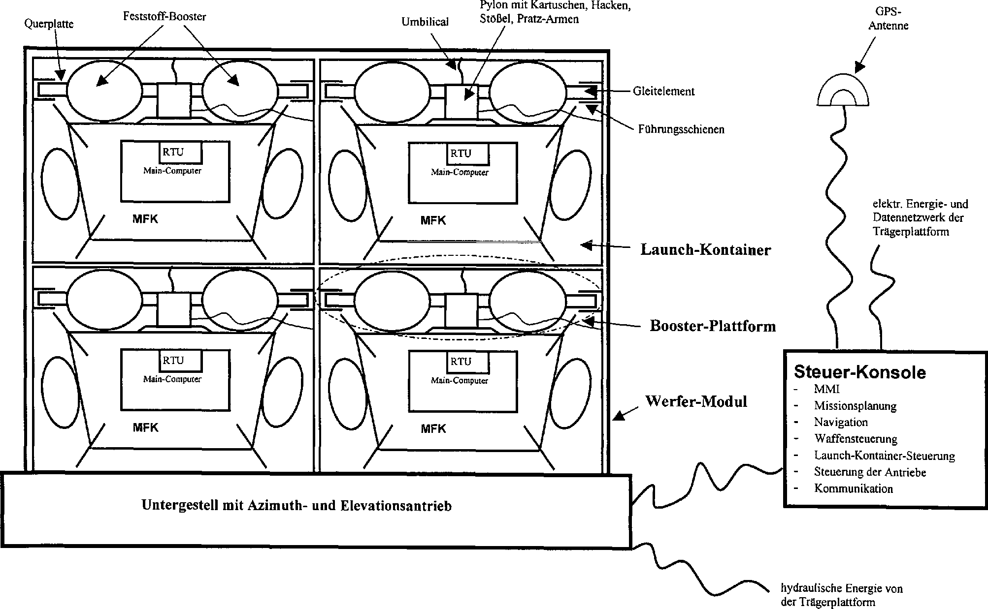
Die Steuer-Konsole stellt via schiffs-internem Netzwerk Status-Informationen bzgl. Gefechtsbereitschaft, Bekämpfungs-Situation, Waffenvorrat etc. zur Verfügung. Falls die Steuer-Konsole in der Stand-Alone-Konfiguration betrieben wird, verfügt sie über ein eigenes GPS-gestütztes Navigationssystem, mittels dem sie die obig genannten Initialisierungs/Alignment-Daten gewinnt, als auch über eigene Einrichtungen, die die Kommunikation mit Gefechts- und Führungsständen erlauben. Sowohl in der Stand-Alone-Version als auch bei der integrierten Version bezieht die Steuer-Konsole elektrische Energie von der Trägerplattform, die sie in die benötigte Form (3 × 115V 400Hz, 28VDC) wandelt. Hydraulische Energie liefert die Trägerplattform für die Azimut- und Elevations-Antrieb des Werfer-Moduls (Untergestell).The control console provides status information regarding combat readiness, combat situation, weapons stock etc. via ship-internal network. If the control console is operated in the stand-alone configuration, it has its own GPS-based navigation system, by means of which it receives the above-mentioned initialization tion / alignment data, as well as its own facilities that allow communication with combat and leadership stadiums. In both the stand-alone version and the integrated version, the control console draws electrical power from the carrier platform, transforming it into the required shape (3 × 115V 400Hz, 28VDC). Hydraulic energy is provided by the carrier platform for the azimuth and elevation propulsion of the launcher module (undercarriage).
Die Steuer-Konsole stellt dem Bediener eine Mensch-Maschine-Schnittstelle zur Verfügung, die ihm folgendes ermöglicht
- – Umsetzung der erhaltenen Bekämpfungs-Aufträge in Missions-Pläne basierend auf Gelände/Objekt-Datenbanken, Aufklärungs-Ergebnissen und aktuellen Wetter-Informationen,
- – Download von Missions-Plänen in die Marschflugkörper im Werfer-Modul,
- – Ausrichtung des Werfer-Moduls in Azimut und Elevation,
- – Aktivierung und Überwachung der Startup-Sequenz eines Marschflugkörpers,
- – Aktivierung und Überwachung des Navigations-Alignments eines Marschflugkörpers,
- – Steuererung und Überwachung der Deckel und des Ver/Entriegelungs-Mechanismus der Launch-Kontainer des Werfer-Moduls,
- – Aktivierung und Überwachnung der Verschußsequenz eines Marschflugkörpers,
- – Aktivierung und Überwachung der Zündung der Booster der Booster-Plattform des aktivierten Marschflugkörpers.
- - Implementation of the received control orders in mission plans based on terrain / object databases, reconnaissance results and current weather information,
- - download mission plans into the cruise missiles in the launcher module,
- Alignment of the launcher module in azimuth and elevation,
- - activation and monitoring of the startup sequence of a cruise missile,
- - activation and monitoring of the navigation alignment of a cruise missile,
- Control and monitoring of the lids and the locking / unlocking mechanism of the launching containers of the launcher module,
- Activation and monitoring of the firing sequence of a cruise missile,
- - Activation and monitoring of the ignition boosters of the booster platform of the activated cruise missile.
Die
Steuer-Konsole hat dazu folgende system-internen Schnittstellen
wie
A. Signale zwischen Steuer-Konsol und Untergestell:A. Signals between control console and underframe:
- – die Steuer-Konsole kommandiert aufgrund von Operator-Eingaben die Azimut- und Elevationsausrichtung an das Werfer-Modul, wozu sie die Ist-Stellung in Azimut und Elevation rückgemeldet erhält.- the Control console commands the azimuth due to operator input and elevation alignment to the launcher module, for which it is the actual position confirmed in azimuth and elevation.
B. Signale zwischen Steuer-Konsole und Launch-KontainerB. signals between control console and launchcontainers
- – die Steuer-Konsole steuert das Auf- und Abklappen des vorderen und hinteren Deckels der Launch-Kontainer bei Beladen/Entladen eines Launch-Kontainers mit einem Marchflugkörper bzw. beim Verschuß eines Marschflugkörpers aus dem Launch-Kontainer,- the Control console controls the folding up and down of the front and rear Lids of launch containers when loading / unloading a launch container with a March missile or at the closure of a Cruise missile from the launch container,
- – die Steuer-Konsole steuert das Ver- und Entriegeln der Führungsschienen des Launch-Kontainers, so dass die Booster-Plattform in den Launch-Kontainer eingeführt, fixiert, verschossen oder entnommen werden kann.- the Control console controls the locking and unlocking of the guide rails the launch container, allowing the booster platform to be inserted into the launch container, fixed, can be shot or taken.
C. Signale zwischen Steuer-Konsole und Booster-PlattformC. Signals between control console and booster platform
- – die Steuer-Konsole stellt via Booster-Plattform die üblichen MIL-STD-1760-Signal-Verbindungen zum im Launch-Kontainer befindlichen Marschflugkörper her: Milbus-Kanäle A und B, diskrete Signale wie DC-PW2, Release-Consent und high bandwidth (HB) Signale (GPS), und die Energieversorgung 3 × 115V 400Hz,- the Control Console provides the usual MIL-STD-1760 signal connections via booster platform in the launch container located cruise missile ago: Milbus channels A and B, discrete signals like DC-PW2, Release-Consent and high bandwidth (HB) signals (GPS), and the power supply 3 × 115V 400Hz,
-
– die
Kodierung der RTU-Adresse des Marschflugkörpers erfolgt durch eine Kodierungs-Logik
in der Booster-Plattform (siehe
4 ), welche manuell einstell- und ablesbar ist, so dass alle Marschflugkörper im Werfer-Modul von der Steuer-Konsole via Milbus eindeutig ansprechbar sind,- The coding of the RTU address of the cruise missile is done by a coding logic in the booster platform (see4 ), which is manually adjustable and readable, so that all cruise missiles in the launcher module from the control console via Milbus are clearly addressable, -
– die
Interlock-Signale sind durch die Booster-Plattform durchgeschleift
(siehe
4 ), so dass das Abreißen des Umbilical-Kabels zwischen Steuer-Konsole und Launch-Kontainer während des Start-Vorganges durch die Steuer-Konsole sensiert werden kann, ebenso eine Hang-Fire-Situation,- the interlock signals are looped through the booster platform (see4 ), so that the demolition of the umbilical cable between the control console and the launch container can be sensed during the boot process by the control console, as well as a hang-fire situation, -
– Signale
zur Zündung
des/der Booster der Booster-Plattform, welche durch eine Sicherheits-Schaltung
in der Booster-Plattform (siehe
5 ) abgesichert sind, wobei die Booster-Zündung durch die Steuer-Konsole erst ausgelöst wird, wenn- Signals to ignite the booster of the booster platform, which by a safety circuit in the booster platform (see5 ), whereby the booster ignition is triggered by the control console only when - – wenn der Marschflugkörper via Milbus den korrekten Ablauf der Release-Sequenz mittels des Milbus-Signales 'Committed to Store Separation' (critical monitor) angezeigt hat und- if the cruise missile via Milbus the correct sequence of the release sequence by means of the Milbus signal 'Committed to Store Separation '(critical monitor) has appeared and
- – wenn die Schalt-Logik der Booster-Plattforms gemeldet hat, dass alle Vorausetzungen für die Booster-Zündung vorliegen und- if the switching logic of the booster platform has reported that all Requirements for the booster ignition present and
- – wenn der Ver/Entriegelungs-Mechanismus des Launch-Kontainers anzeigt, dass die Gleitelemente der Booster-Plattform in den Führrungsschienen des Launch-Kontainers entriegelt sind und - if the lock / unlock mechanism of the launch container indicates that the sliding elements of the booster platform in the guide rails of the launch container are unlocked and
- – wenn der vorderne und der hintere Deckel des Launch-Kontainers als aufgeklappt sensiert werden.- if the front and rear lids of the launch container unfolded be sensed.
- – Signale, die anzeigen, ob obige Sicherheits-Schaltung die Booster-Zündung freigibt oder sperrt,- signals, indicating whether the above safety circuit releases the booster ignition or locks,
- – Signale, die anzeigen, ob der Sicherheits-Pin der Booster-Plattform noch steckt oder schon gezogen ist, wobei diese Information an der Mensch-Maschine-Schnittstelle der Steuer-Konsole visualisiert wird.- signals, which indicate if the security pin is still the booster platform infected or already pulled, with this information at the man-machine interface the control console is visualized.
Ein
oder mehrere Launch-Kontainer sind im Werfer-Modul fest installiert
(siehe
Am
vorderen und hinteren Ende des Launch-Kontainers ist jeweils ein
steuerbarer Deckel angebracht, die aufklapp- und abklappbar sind.
Sensoren ermittelt die jeweilige Stellung und melden sie an die
Steuer-Konsole bzw. an den Verkabelungs- und Logik-Schaltkasten
der Booster-Plattform (siehe
Die
Booster-Plattform besteht aus folgenden Elementen (siehe
- – eine Querplatte, die mittig den Schwerlast-Pylon aufnimmt und die an beiden Ende jeweils ein Gleitelement besitzt, welche jeweils in einer Führungsschiene des Launch-Kontainers geführt bzw. fixiert sind. An die Querplatte sind zudem 2 Booster angeflanscht.
- – einen Schwerlast-Pylon, der mittig an die Querplatte montiert ist. Dieser Schwerlast-Pylon hat die selbe Funktionalität wie die bei Torando IDS Jagdbombern für Marschflugkörper benutzten Schwerlast-Pylons (Waffenstation left shoulder/right shoulder). Somit sind vorhanden
- – ein Mechanismus zum Ver- und Entriegeln der Ösen des Marschflugkörpers,
- – Pratzarme zum seitlichen Fixierung des Marschflugkörpers an dessen Abpratzflächen,
- – Stößel zum Wegdrücken des Marschflugkörpers bei Release bzw. Jettision, deren Abstoßkraft entstellbar ist,
- – manueller Mechanismus zum Ver/Entriegeln der Ösen und zum Anbringen/Entfernen der Abpratzarme,
- – ein Kartuschen-Mechanismus, durch dessen Zündung die Ösen des Marschflugkörpers entriegelt, die Pratzarme von den Abpratzflächen des Marschflugkörpers entfernt und die Stößel den Marschflugkörper wegdrücken. Dabei werden die Zündleitungen vom Marschflugkörper via unterem Umbilical-Kabel zugeführt.
- – ein
Mechanismus (siehe
6 ), der den Plunger des Marschflugkörpers nur dann ausfahren läßt, wenn der Sicherheits-Riegel der Booster-Plattform mittels Release-Leine gezogen ist. Damit wird erreicht, dass beim Marschflugkörper TAURUS KEPD350 unmittelbar nach vollständigem Verlassens des Launch-Kontainers der Plunger (Länge der Release-Leine ist entspr. dimensioniert) ausfährt, wodurch nach Ablauf des Timers der LANSAD die 'Arm-Power' anliegt, die das Ausfahren der Wings und den Start des Triebwerks des Marschflugkörpers ermöglicht, - – ein
Mechanismus (siehe
6 ), der die Zündung der Kartuschen erst dann freischaltet, wenn der Sicherheits-Riegel durch die Release-Leine gezogen ist. Dadurch wird sichergestellt, dass die Kartuschenzündung nicht im Launch-Kontainer erfolgen kann, sondern erst, wenn der Marschflugkörper den Launch-Kontainer verlassen hat. - – Booster, welche an die Querplatte angeflanscht sind und zusammen eine Schubkraft von circa 130kN/Ssec (bei ≈ 1400kg MFK-Masse) bei einer Treibstoffmasse von circa 200kg erzeugen. Dadurch kann der Marschflugkörper 5sec nach Booster-Zündung auf eine Geschwindigkeit > 0.7 Mach beschleunigt werden, wobei er bei einem Start-Elevationswinkel (kein Wind) von ≈ 17° eine Höhe von ≈ 80m (t = 5sec, Entfernung ≈ 800m) erreicht bzw. bei einem Start-Elevationswinkel (kein Wind) von ≈ 30° eine Höhe von ≈ 400m (t = 10sec, Entfernung ≈ 1800m), was aus flugmechanische Simulationen abgeleitet werden kann. Der/die verwendeten Booster können aufgrund der zur Verfügung stehenden Baulänge (maximal die Länge des Marschflugkörpers) als COTS (commercial off-the-shelf) oder als MOTS (military off-the-shelf) beschaft werden.
- – oberes
Umbilical-Kabel, das auf den inneren Umbilical-Stecker des Launch-Kontainers aufgeschraubt
wird und das alle Signale von Marschflugkörper, Booster-Plattform und Launch-Kontainer
zur Steuer-Konsole enthält
(siehe auch
2 ). - – unteres
Umbilical-Kabel, das auf den Umbilical-Stecker des Marschflugkörpers aufgeschraubt wird
und das alle Signale enthält,
welche Marschflugkörper
und Booster-Plattform verbinden (siehe auch
2 ). - – Sicherheits-Pin
(siehe
6 ), der nur manuell bedient werden kann und welcher im gesteckten Zustand die Zündung der Booster der Booster-Plattform mechanisch blockiert. - – Verkabelungs-
und Logik-Schaltkasten, der eine Schalt-Logik enthält, die
eine unbeabsichtigte Auslösung
der Booster-Zündung
verhindert. Die Zündung
der Booster wird nur dann freigeschaltet, wenn (siehe
5 ) - – sowohl der vorderne als auch der hintere Deckel des Launch-Kontainers als aufgeklappt gemeldet wird und
- – beide Führungsschienen melden, dass die Gleitelemente der Booster-Plattform entriegelt sind und
- – der Sicherheits-Pin der Booster-Plattform gezogen ist und
- – die Signale DC-PW2 und Release-Consent (siehe MIL-STD-1760C) von der Steuer-Konsole aktiviert worden sind und
- – vom Marschflugkörper das Booster-Enable-Signal aktiviert worden ist. Dadurch kann die Steuer-Konsole die Booster-Zündung erst dann auslösen, wenn alle mechanischen Voraussetzungen vorliegen und wenn der Marschflugkörper signalisiert, dass er verschußbereit ist. Der Steuer-Konsole wird ein Signal zur Verfügung gestellt, welches das Ergebnis der obigen Und-Verknüpfungsschaltung repräsentiert.
- – RTU-Adress-Kodierungs-Schaltung
(siehe
4 ), durch welche die Milbus-RTU-Adresse des an der Booster-Plattform hängenden Marschflugkörpers definiert wird. Diese Schaltung ist manuell konfigurierbar und die eingestellte RTUI-Adresse ist an einem kleinem Display ablesbar. Falls mehrere Booster-Plattformen mit jeweils einem Marschflugkörper durch die Steuer-Konsole anzusteuern sind, kann dadurch jeder Marschflugkörper eindeutig via Milbus angesprochen werden.
- - A transverse plate which receives the heavy duty pylon in the middle and which has a respective sliding element at both ends, which are each guided or fixed in a guide rail of the launch container. On the cross plate also 2 boosters are flanged.
- - A heavy duty pylon, which is mounted centrally on the transverse plate. This heavy duty pylon has the same functionality as the heavy duty pylons used in Torando IDS cruise missiles for cruise missiles (Waffenstation left shoulder / right shoulder). Thus, there are
- A mechanism for locking and unlocking the eyes of the cruise missile,
- - Pratzarme for lateral fixation of the cruise missile at the Abprüatzflächen,
- - ram for pushing away the cruise missile at release or jettison, whose repelling force is disfigurable,
- Manual mechanism for locking / unlocking the eyes and for attaching / removing the arms,
- - A cartridge mechanism, by the ignition of which unlocks the eyes of the cruise missile, the luffing arms removed from the strike surfaces of the cruise missile and the plunger push away the cruise missile. The ignition cables are fed from the cruise missile via the lower umbilical cable.
- - a mechanism (see
6 ), which can extend the plunger of the cruise missile only when the safety bolt of the booster platform is pulled by means of a release leash. This ensures that in the cruise missile TAURUS KEPD350 immediately after completely leaving the launch container, the plunger (length of the release leash is dimensioned accordingly) extends, so after the expiration of the timer, the LANSAD the 'arm power' is applied, the extension the wings and the start of the engine of the cruise missile allows - - a mechanism (see
6 ), which releases the ignition of the cartridges only when the safety latch is pulled through the release leash. This ensures that the cartridge ignition can not be done in the launch container, but only when the cruise missile has left the launch container. - - Booster, which are flanged to the transverse plate and together generate a thrust of about 130kN / sec (at ≈ 1400kg MFK mass) at a fuel mass of about 200kg. As a result, the cruise missile can be accelerated to a speed of> 0.7 Mach after a booster ignition for 5 seconds, reaching a height of ≈ 80 m (t = 5 sec, distance ≈ 800 m) at a start elevation angle (no wind) of ≈ 17 °. at a start-elevation angle (no wind) of ≈ 30 ° a height of ≈ 400m (t = 10sec, distance ≈ 1800m), which is derived from flight mechanics Simulations can be derived. The booster (s) used may be considered COTS (commercial off-the-shelf) or MOTS (military off-the-shelf) due to the available overall length (maximum length of the cruise missile).
- - Upper umbilical cable, which is screwed onto the inner umbilical plug of the launch container and which contains all signals from cruise missile, booster platform and launch container to the control console (see also
2 ). - - Lower umbilical cable, which is screwed onto the umbilical plug of the cruise missile and which contains all the signals that connect the cruise missile and the booster platform (see also
2 ). - - Safety pin (see
6 ), which can only be operated manually and which, when plugged in, mechanically blocks the ignition of the boosters of the booster platform. - - Wiring and logic control box, which contains a switching logic that prevents unintentional triggering of the booster ignition. The ignition of the booster will only be unlocked if (see
5 ) - - Both the front and the rear lid of the launch container is reported as unfolded and
- - both guide rails signal that the sliding elements of the booster platform are unlocked and
- - the safety pin of the booster platform is pulled and
- - The signals DC-PW2 and Release-Consent (see MIL-STD-1760C) have been activated by the control console and
- - From the cruise missile, the booster enable signal has been activated. As a result, the control console can trigger the booster ignition only when all mechanical conditions are met and when the cruise missile signals that it is ready to fire. The control console is provided with a signal representing the result of the above AND logic circuit.
- - RTU address coding circuit (see
4 ) that defines the Milbus RTU address of the cruise missile attached to the booster platform. This circuit can be configured manually and the set RTUI address can be read on a small display. If several booster platforms with one cruise missile each are to be controlled by the control console, each cruise missile can be addressed clearly via Milbus.
Der Marschflugkörper vom Typ TAURUS KEPD350 muß geringfügig hinsichtlich Hardware modifiziert werden, um an einer Booster-Plattform hängend aus einem Launch-Kontainer von der Steuer-Konsole kontrolliert verschoßen werden zu können:
- – von
der Safety and Ignition Unit (SIU) des Marschflugkörpers muss
ein zusätzliches,
diskretes Zündsignal
zum Umbilical-Stecker des Marschflugkörpers verkabelt werden, das
in die Booster-Plattform geführt
wird und die Zündenergie
für die
Kartuschen-Zündung
liefert (siehe
6 'Kartuschen-Zündsignal') - – von
der Safety and Ignition Unit (SIU) des Marschflugkörpers muss
ein zusätzliche
diskretes Signal zum Umbilical-Stecker des Marschflugkörpers verkabelt
werden, das in die Schalt-Logik für die Booster-Zündung des
Verkabelungs- und Logik-Schaltkasten
(Booster-Plattform) eingeht und das eine Booster-Zündung im
deaktivierten Zustand blockiert (siehe
5 'Booster-Enable-Signal').
- - the cruise missile's Safety and Ignition Unit (SIU) requires an additional, discrete ignition signal to be wired to the cruise missile umbilical connector, which is routed into the booster platform and provides ignition power for the cartridge ignition (see
6 'Cartridge ignition signal') - - the cruise missile's Safety and Ignition Unit (SIU) requires an additional discrete signal to be wired to the cruise missile umbilical connector, which is included in the Booster Ignition Switching logic of the Cabling and Logic Control Box (Booster Platform) and that blocks a booster ignition in the deactivated state (see
5 'Booster enable signal').
Folgende Soft- bzw. Firmware-Modifikationen des Marschflugkörper vom Typ TAURUS KEPD350 sind erforderlich:
- – die Delay-Time
des LANSAD-Timers muß auf < 0.5 sec verringert
werden, um unmittelbar nach Detektion des Plunger-Ausfahrens (Release-Leine
zieht Sicherheits-Riegel,
siehe
6 ) die 'Arm-Power' (safe = false, arm = true) zur Verfügung zu haben, so dass die Wings ausgefahren und das Triebwerk des Marschflugkörpers gestartet werden kann - – der Main-Computer des Marschflugkörpers darf mittels internem Bus der Safety and Ignition Unit (SIU) die Aktivierung des Booster-Enable-Signals nur dann kommandieren, wenn
- – wenn der Marschflugkörper den korrekten Ablauf der Release-Sequenz via Milbus durch das MIL-STD-1760C-Signal 'Committed to Store Separation' (critical monitor) der Steuer-Konsole via Milbus gemeldet hat, wobei die Safety and Ignition Unit (SIU) des Marschflugkörpers das Booster-Enable-Signal nur dann zur Booster-Plattform weiterleitet, wenn sie bereits den Kommand-Kode 'Plunger-Unlock' (PLA arm) ausgeführt hat (dadurch wird die Booster-Zündung mit der Fähigkeit verknüpft, das vollständige Verlassen des Launch-Kontainers mittels Plunger zu sensieren)
- – der
Main-Computer des Marschflugkörpers
darf mittels internem Bus der Safety and Ignition Unit (SIU) die
Aktivierung des Kartuschen-Zündsignales
(siehe
6 ) nur dann kommandieren, wenn - – wenn der Plunger des Marschflugkörpers sensiert hat, dass der Marschflugkörper den Launch-Kontainer vollständig verlassen hat und
- – wenn seit Verlassen des Launch-Kontainers mindestens 3sec vergangen sind und
- – wenn die Navigation des Marschflugkörpers das Abklingen des Booster- Schubes sensiert. Die Zündung der Kartuschen wird allerdings spätestens 7sec nach Verlassen des Launch-Kontainers unabhängig von obigen Bedingungen aktiviert. Die Safety and Ignition Unit (SIU) des Marschflugkörpers führt das Kommando zur Kartuschen-Zündung nur dann aus, wenn sie bereits den Kommand-Kode zum Triebwerksstart (PCS arm) ausgeführt hat.
- – im Main-Computer muß eine Funktion implemeniert werden, die den Schubverlauf der Booster aufgrund von Navigationsdaten sensiert und überwacht, so dass eindeutig der Booster-Start und der Brennschluß der Booster erkannt werden.
- – im Main-Computer muß die Separation-Lenkung sowie die Fin-Preset-Winkel an den Verschuß mit Booster angepaßt werden, insbesondere muß sofort nach Booster-Zündung eine Rollwinkel- und Nickwinkel-Regelung einsetzen, die die Booster-Plattform samt Marschflugkörper auf einer Startflugbahn mit Elevations-Start-Winkel und konstantem Gierwinkel bis Kartuschen-Zündung lenken.
- – die Ablaufsteuerung des Main-Computers muss so modifiziert werden, dass unmittelbar nach Sensierung des Plunger-Ausfahrens das Aufklappen der Wings und der Start des Triebwerks initiert werden.
- – die Ablaufsteuerung des Main-Computers erhält somit den neuen Zustand 'Boost-Mode', der die Separations-Modi der luftgestützten Marschflugkörper-Version ersetzt
- – nach Trennnung von der Booster-Plattform durch Kartuschen-Zündung wird vom Zustand 'Boost-Mode' in den 'Cruise-Mode' übergegangen, in dem die preplanned/replanned Mission dann durchgeführt wird, wenn der Triebwerkshochlauf (idle speed liegt an) vollendet ist (circa 8-12sec nach Start).
- - The delay time of the LANSAD timer must be reduced to <0.5 sec., Immediately after detection of the plunger extension (release leash pulls safety catch, see
6 ) to have the 'arm-power' (safe = false, arm = true) available, so that the wings can be extended and the engine of the cruise missile can be started - - The main computer of the cruise missile may command the activation of the booster enable signal via internal bus of the Safety and Ignition Unit (SIU) only if
- - when the cruise missile has reported the correct Milbus release sequence through the Milbus M console console's MIL-STD-1760C 'Committed to Store Separation' (critical monitor) signal, with the Safety and Ignition Unit (SIU) of the cruise missile only passes the booster enable signal to the booster platform if it has already executed the command code 'plunger unlock' (PLA arm) (this links the booster ignition to the ability to completely exit the booster To detect launch containers using plungers)
- - The main computer of the cruise missile may by means of internal bus of the Safety and Ignition Unit (SIU), the activation of the cartridge ignition signal (see
6 ) command only if - - if the plunger of the cruise missile has sensed that the cruise missile has completely left the launch container and
- - if at least 3 seconds have elapsed since leaving the launch container and
- - if the navigation of the cruise missile senses the decay of the booster thrust. However, the ignition of the cartridges is activated no later than 7 seconds after leaving the launch container regardless of the above conditions. The cruise missile's Safety and Ignition Unit (SIU) will only execute the cartridge ignition command if it has already executed the engine start command code (PCS arm).
- - In the main computer, a function must be implemented, which senses and monitors the thrust curve of the booster due to navigation data, so that clearly the booster start and the burnout of the booster are detected.
- - In the main computer, the separation steering and the fin-preset angle must be adapted to the Verschuß with booster, in particular must immediately after booster ignition roll angle and pitch control use that the booster platform together with cruise missiles on a Start trajectory with elevation start angle and constant yaw angle to steer cartridge ignition.
- - The flow control of the main computer must be modified so that immediately after sensing the plunger extension the wings are opened and the engine is started.
- - The flow control of the main computer thus receives the new state 'boost mode', which replaces the separation modes of the airborne cruise missile version
- - After separation from the booster platform by cartridge ignition, the state goes from 'Boost-Mode' to 'Cruise-Mode', where the preplanned / replanned mission is executed when the engine idle speed is completed is (about 8-12sec after takeoff).
Nachfolgend wird sequenziell beschrieben, wie das vorgeschlagene System operationell benutzt wird:
- 1. der Marschflugkörper wird im Storage/Transport-Kontainer angeliefert, ausgepackt und die Ruder aufgeschraubt. Danach wird der Marschflugkörper aufgetankt,
- 2. eine Booster-Plattform wird ebenso in einem Storage/Transport-Kontainer angeliefert, die RTU-Adresse wird eingestellt und die Sicherheits-Einrichtungen der Booster-Plattform werden überprüft,
- 3. die Booster-Plattform wird auf den Marschflugkörper mittels eines Kranes aufgesetzt, so dass der Spigot des Marschflugkörpers in das zugehörige Loch der Booster-Plattform paßt und die Ösen des Marschflugkörpers manuell in der Booster-Plattform verriegelt werden können, die Pratzen der Booster-Plattform fixieren den Marschflugkörper seitlich durch Aufliegen auf den Abpratzflächen,
- 4. das untere Umbilical-Kabel der Booster-Plattform wird auf den Umbilical-Stecker des Marschflugkörpers aufgeschraubt,
- 5. der vordere Deckel des Launch-Kontainers wird mittels Steuer-Konsole geöffnet,
- 6. die Booster-Plattform mit angehängten Marschflugkörper wird mittels Kran zum Launch-Kontainer transportiert, die Release-Leine der Booster-Plattform im Launch-Kontainer eingehackt, die Gleitelemente der Booster-Plattform werden in die entriegelten Führungsschienen des Launch-Kontainers eingefädelt, die Booster-Plattform samt Marschflugkörper in den Launch-Kontainer eingeschoben und das obere Umbilical-Kabel der Booster-Plattform durch die geöffnete Bedienungs-Klappe auf den inneren Umbilical-Stecker des Launch-Kontainers aufgeschraubt,
- 7. mittels Steuer-Konsole werden die Führungsschienen des Launch-Kontainers verriegelt,
- 8. der vordere Deckel des Launch-Kontainers wird mittels Steuer-Konsole zugeklappt,
- 9. mittels Bedienerklappe wird manuell der Sicherheits-Pin der Booster-Plattform gezogen,
- 10. die Schritte 1–9 werden wiederholt, bis alle Launch-Kontainer des Werfer-Moduls mit Booster-Plattformen und Marschflugkörper beladen sind,
- 11. falls ein Bekämpfungs-Auftrag befohlen wird, erfolgt nun die bekannte Missions-Planung für den Marschflugkörper, die sich nicht von der Missions-Planung für die luftgestützte Version (Jagdbomber) des Marschflugkörpers unterscheidet, mittels Steuer-Konsole,
- 12. wenn der Missions-Plan erstellt und das Verschußgebiet erreicht ist, wird ein Marschflugkörper im Werfer-Modul aktiviert (power on), so daß dieser seine Startup-Sequenz (PBIT, IBIT etc..) durchläuft,
- 13. die Selbsttestergebnisse des Marschflugkörpers werden an der Steuer-Konsole visualisiert, ebenso der Status der sicherheits-relevanten Signale, so dass der Bediener jederzeit im Falle von einer Fehlfunktion abbrechen kann,
- 14. der Missions-Plan wird von der Steuer-Konsole mittels Milbus in den Marschflugkörper geladen,
- 15. GPS-Initialisierungs-Daten bezieht die Steuer-Konsole aus dem Datennetz der Trägerplattform und übermittelt sie dem Marschflugkörper, der damit sein eigenes GPS initialisiert,
- 16. des Navigations-Alignment des Marschflugkörpers wird mittels Steuer-Konsolen-Befehl aktiviert, wobei die Steuer-Konsole Navigations-Daten der Trägerplattform zyklisch an den Marschflugkörper übermittelt,
- 17. erreicht die Trägerplattform die vorgeplannte Verschußstelle, wird das Werfer-Modul in die vorgeplannte Azimut- und Elevation-Stellung mittels Steuer-Konsole positioniert,
- 18. mittels Steuer-Konsolen-Befehl wird der vordere und der hintere Deckel des Launch-Kontainers, dessen Marschflugkörper zu verschiessen ist, aufgeklappt,
- 19. mittels Steuer-Konsolen-Befehl werden die Führungsschienen des Launch-Kontainers entriegelt,
- 20. mittels Steuer-Konsolen-Befehl wird die Release-Sequenz des Marschflugkörpers (Start der Thermalbatterie, Fin-Unlock, Fin-Preset etc..) aktiviert,
- 21. wenn der Marschflugkörper
der Steuer-Konsole das Milbus-Signal 'Committed to Store Separation' meldet, aktiviert
die Steuer-Konsole die Zündung
der Booster der Booster-Plattform, falls alle anderen Sicherheits-Bedingungen
erfüllt
sind (siehe
7 ), - 22. die Booster der Booster-Plattform entwickeln schlagartig
Schub und beschleunigen die Booster-Plattform samt angehängtem Marschflugkörper aus
den Launch-Kontainer (siehe
8 ), - 23. die Release-Leine zieht den Sicherheits-Riegel der Booster-Plattform,
wenn der Marschflugkörper
mit voller Länge
den Launch-Kontainer verlassen hat (siehe
9 ,10 ) - 24. wenn der Sicherheits-Riegel aus der Booster-Plattform gezogen ist, fährt unmittelbar danach der Plunger des Marschflugkörpers nach oben aus, was das Start-Ereignis für die Aktivierung des Wingdeployments und des Triebwerkshochlauf ist,
- 25. nach 5sec befindet sich der Marschflugkörper in circa 80m Höhe über See, falls er mit einem Elevationswinkel von circa 17° verschossen wurde, und ist auf eine Geschwindigkeit zwischen 0.7 Mach und 0,8 Mach beschleunigt worden,
- 26. der Booster-Schub setzt schlagartig aus, was durch das Navigations-System des Marschflugkörpers sensiert wird, worauf der Marschflugkörper die Zündung der Kartuschen der Booster-Plattform aktiviert,
- 27. die Kartuschen zünden,
worauf die Ösen
des Marschflugkörpers
in der Booster-Plattform
entriegelt werden, die Pratzarme der Booster-Plattform sich von
den Abpratzflächen
des Marschflugkörpers
lösen und
die Stößel der
Booster-Plattform die Booster-Plattform vom Marschflugkörper wegdrücken (siehe
11 ), - 28. der Marschflugkörper
ist von der Booster-Plattform getrennt, 10–12sec nach Verlassen des Launch-Kontainers
liefert das Triebwerk des Marschflugkörpers ausreichend Schub, um
die vorgeplannte Marschphase aufzunehmen (siehe
12 ).
- 1. The cruise missile is delivered to the storage / transport container, unpacked and the rudders screwed on. Then the cruise missile is refueled,
- 2. a booster platform is also delivered in a storage / transport container, the RTU address is set and the booster platform security features are checked,
- 3. the booster platform is mounted on the cruise missile by means of a crane so that the cruise missile's spigot fits into the associated hole of the booster platform and the cruise ship's eyelets can be manually locked in the booster platform, the lugs of the booster Platform fix the cruise missile laterally by resting on the Abprüatzflächen,
- 4. the lower umbilical cable of the booster platform is screwed onto the umbilical plug of the cruise missile,
- 5. the front lid of the launch container is opened by means of the control console,
- 6. the booster platform with attached cruise missiles is transported by crane to the launch container, the release leash of the booster platform hacked in the launch container, the sliding elements of the booster platform are threaded into the unlocked guide rails of the launch container, the Insert the booster platform together with the cruise missile into the launch container and screw the upper umbilical cable of the booster platform through the open control flap onto the inner umbilical plug of the Launch container.
- 7. the guide rails of the launch container are locked by means of the control console,
- 8. the front lid of the launch container is closed by means of the control console,
- 9. by means of the operator flap, the safety pin of the booster platform is pulled manually,
- 10. Steps 1-9 are repeated until all launch containers of the launcher module are loaded with booster platforms and cruise missiles.
- 11. If a combat mission is commanded, the well-known cruise missile mission planning, which does not differ from mission planning for the airborne version (fighter-bomber) of the cruise missile, now takes place via the control console,
- 12. When the mission plan is created and the fuselage area is reached, a cruise missile is activated in the launcher module (power on), so that it goes through its startup sequence (PBIT, IBIT etc.),
- 13. the self-test results of the cruise missile are visualized on the control console, as well as the status of the safety-relevant signals, so that the operator can stop at any time in case of malfunction,
- 14. the mission plan is loaded into the cruise missile by the control console via Milbus,
- 15. GPS initialization data gets the control console from the carrier network's data network and transmits it to the cruise missile, which initializes its own GPS,
- 16. the navigation alignment of the cruise missile is activated by means of the control console command, whereby the control console transmits navigation data of the carrier platform cyclically to the cruise missile,
- 17. When the carrier platform reaches the pre-planned point of impact, the launcher module is positioned in the pre-planned azimuth and elevation position by means of the control console,
- 18. By means of Control Console command, the front and the rear cover of the launch Kontai ners, whose cruise missile is to be fired, unfolded,
- 19. Control Console Command unlocks the Launch Container's rails,
- 20. by means of control console command the release sequence of the cruise missile is activated (start of the thermal battery, fin-unlock, fin-preset etc.),
- 21. When the Control Console cruise missile reports the Milbus Committed to Store Separation signal, the Control Console will activate the booster platform's booster firing if all other safety conditions are met (see
7 ) - 22. boosters booster boost and accelerate the booster platform with attached cruise missile from the launch container (see
8th ) - 23. the release leash pulls the booster platform safety bar when the full-length cruise missile has left the launch container (see
9 .10 ) - 24. When the safety bar has been pulled out of the booster platform, immediately after that, the plunger of the cruise missile exits upwards, which is the start event for the activation of the wing deployment and the engine ramp,
- 25. after 5sec, the cruise missile is about 80m above sea level, if it was fired at an elevation angle of about 17 °, and has been accelerated to a speed between 0.7 Mach and 0.8 Mach,
- 26. the booster thrust abruptly stops, which is sensed by the navigation system of the cruise missile, whereupon the cruise missile activates the ignition of the booster platform's cartridges,
- 27. ignite the cartridges, whereupon the cruise ship eyelets in the booster platform are unlocked, the booster platform pry arms disengage from the cruise missile strike surfaces, and the booster platform plungers push the booster platform away from the cruise missile (see
11 ) - 28. the cruise missile is disconnected from the booster platform, 10-12 seconds after leaving the launch container, the engine of the cruise missile provides sufficient thrust to accommodate the pre-planned cruise phase (see
12 ).
Vorteile der ErfindungAdvantages of the invention
Die dargestellte Erfindung hat mehrere Vorteile:
- – das taktisches Einsatzspektrum eines bisher nur luftgestützten Marschflugkörpers vergrößert sich durch die Möglichkeit der Seestützung bzw. der Bodenstützung, wodurch eine Vergrößerung des Kundenpotentials einhergeht,
- – es ergeben sich Kosten-Einsparungs-Potentiale, weil
- – kein neuer Airframe entwickelt werden muß (im Gegensatz zu Scalp EG),
- – keine
risikobehaftete und aufwändige
Integration eines Booster-Modules hinter dem Triebwerk durchgeführt werden
muß (siehe
US5131223 - – kein neuer Mechanismus integriert werden muß, mit dem eine gesteuerte Trennung des Boosters vom Marschflugkörper nach Brennschluß herbeigeführt werden kann,
- – MOTS- bzw. COTS-Booster verwendet werden kann,
- – die Entwicklung von Startgerät und Booster-Aufhängung weniger komplex ist als die Neuentwicklung eines Airframes,
- – der Anpassungs-Bedarf des luftgestützten Marschflugkörpers hauptsächlich Software betrifft und nur geringfügig Hardware,
- – das gleiche Equipment für Produktion, Wartung und Logistik benutzt werden kann, das auch für die luftgestützte Marschflugkörper-Version in Nutzung ist,
- – durch die vorgeschlagene Lösung sollte der Marschflugkörper-Einsatz auch von Versorgungsschiffen der Lüneburg-Klasse, von Tendern der Elbe-Klasse, von Einsatzgruppenversorgern der Berlin-Klasse oder von Flottendienstbooten der Oste-Klasse möglich werden (→ Kontainerisierung), was eine kostspielige Integration von Marschflugkörper-Systemen in Fregatten (Sachsen-Klasse) oder Korvetten (K130) überflüssig machen könnte.
- - The tactical range of use of a previously only airborne cruise missile increases by the possibility of Seestützung or the ground support, which is accompanied by an increase in customer potential,
- - There are cost-saving potentials, because
- - no new airframe needs to be developed (in contrast to Scalp EG),
- - no risky and time-consuming integration of a booster module behind the engine must be performed (see
US5131223 - - no new mechanism must be integrated, with which a controlled separation of the booster from the cruise missile after combustion can be brought about,
- - MOTS or COTS booster can be used,
- The development of launch device and booster suspension is less complex than the redesign of an air frame,
- - the need for adaptation of the airborne cruise missile mainly concerns software and only minor hardware,
- - The same equipment can be used for production, maintenance and logistics, which is also used for the airborne cruise missile version,
- - The proposed solution, the cruise missile deployment should also by supply vessels of the Lüneburg class, by Elbe-class tenders, by Einsatzgruppenversörern the Berlin class or by fleet service boats of the Eastern class are possible (→ Kontainerisierung), which is a costly integration of Cruise missile systems in frigates (Sachsen class) or corvettes (K130) could make superfluous.
Claims (13)
Priority Applications (1)
| Application Number | Priority Date | Filing Date | Title |
|---|---|---|---|
| DE2003156157 DE10356157B4 (en) | 2003-12-02 | 2003-12-02 | Procedures and devices for cruise missile firing via booster platform |
Applications Claiming Priority (1)
| Application Number | Priority Date | Filing Date | Title |
|---|---|---|---|
| DE2003156157 DE10356157B4 (en) | 2003-12-02 | 2003-12-02 | Procedures and devices for cruise missile firing via booster platform |
Publications (2)
| Publication Number | Publication Date |
|---|---|
| DE10356157A1 DE10356157A1 (en) | 2005-07-07 |
| DE10356157B4 true DE10356157B4 (en) | 2006-06-14 |
Family
ID=34638242
Family Applications (1)
| Application Number | Title | Priority Date | Filing Date |
|---|---|---|---|
| DE2003156157 Expired - Fee Related DE10356157B4 (en) | 2003-12-02 | 2003-12-02 | Procedures and devices for cruise missile firing via booster platform |
Country Status (1)
| Country | Link |
|---|---|
| DE (1) | DE10356157B4 (en) |
Families Citing this family (2)
| Publication number | Priority date | Publication date | Assignee | Title |
|---|---|---|---|---|
| DE102006029147A1 (en) | 2006-06-24 | 2008-01-03 | Lfk-Lenkflugkörpersysteme Gmbh | Device for deploying unmanned aerial vehicles from an aircraft |
| DE102010022728A1 (en) * | 2010-06-04 | 2011-12-08 | Diehl Bgt Defence Gmbh & Co. Kg | Method for instructing a missile on a target |
Citations (6)
| Publication number | Priority date | Publication date | Assignee | Title |
|---|---|---|---|---|
| DE1678575A1 (en) * | 1968-01-16 | 1972-01-05 | Dynamit Nobel Ag | Procedure for launching missiles |
| US3742813A (en) * | 1970-12-14 | 1973-07-03 | Us Navy | Missile launcher |
| US3769876A (en) * | 1972-08-02 | 1973-11-06 | Us Navy | Missile launching canister |
| DE3008015A1 (en) * | 1980-03-01 | 1981-09-10 | Vereinigte Flugtechnische Werke Gmbh, 2800 Bremen | Catapult with sloping track for flying body - has lower hydraulic shock absorber and pneumatic shock absorber for carriage at top |
| US5131223A (en) * | 1989-07-13 | 1992-07-21 | Sundstrand Corporation | Integrated booster and sustainer engine for a missile |
| DE19716025A1 (en) * | 1997-04-17 | 1998-10-22 | Bodenseewerk Geraetetech | Platform with sensors and computer network for launching target-tracking missile |
-
2003
- 2003-12-02 DE DE2003156157 patent/DE10356157B4/en not_active Expired - Fee Related
Patent Citations (6)
| Publication number | Priority date | Publication date | Assignee | Title |
|---|---|---|---|---|
| DE1678575A1 (en) * | 1968-01-16 | 1972-01-05 | Dynamit Nobel Ag | Procedure for launching missiles |
| US3742813A (en) * | 1970-12-14 | 1973-07-03 | Us Navy | Missile launcher |
| US3769876A (en) * | 1972-08-02 | 1973-11-06 | Us Navy | Missile launching canister |
| DE3008015A1 (en) * | 1980-03-01 | 1981-09-10 | Vereinigte Flugtechnische Werke Gmbh, 2800 Bremen | Catapult with sloping track for flying body - has lower hydraulic shock absorber and pneumatic shock absorber for carriage at top |
| US5131223A (en) * | 1989-07-13 | 1992-07-21 | Sundstrand Corporation | Integrated booster and sustainer engine for a missile |
| DE19716025A1 (en) * | 1997-04-17 | 1998-10-22 | Bodenseewerk Geraetetech | Platform with sensors and computer network for launching target-tracking missile |
Also Published As
| Publication number | Publication date |
|---|---|
| DE10356157A1 (en) | 2005-07-07 |
Similar Documents
| Publication | Publication Date | Title |
|---|---|---|
| EP1873058B1 (en) | Device for dropping unmanned aerial vehicles from an aircraft | |
| DE69726292T2 (en) | Low Earth-ORBIT-START SYSTEM | |
| DE2935044A1 (en) | UNMANNED MISSILE TO BE LAUNCHED FROM A CONTAINER | |
| EP1752376A2 (en) | Aircraft, in particular unmanned aircraft, with at least one weapons bay | |
| DE3234268A1 (en) | ROCKET LAUNCHER FOR AIRCRAFT | |
| WO2011002331A1 (en) | Small unmanned aircraft system | |
| EP1806287B1 (en) | Device and Method for automatic detachment of weapons from an extension platform after parachute extraction | |
| DE69911816T2 (en) | CONTROL METHOD FOR AEROSPACE SYSTEM FOR CARRYING A PAYLOAD ON AN ORBIT | |
| DE10342565B4 (en) | Apparatus and method for landing of cruise missiles by Airdrop launchers from transport aircraft | |
| DE102013002717A1 (en) | Method for operating a stationary missile | |
| DE102004042990A1 (en) | Device for testing an operational cruise missile, allows testing without performing any irreversible operation | |
| EP2428445A2 (en) | Method for releasing an unmanned aerial vehicle from an aircraft | |
| DE10338963B4 (en) | Take-off platform for the deployment of missiles from a transport flight by parachute | |
| DE10356157B4 (en) | Procedures and devices for cruise missile firing via booster platform | |
| EP2381205B1 (en) | Method for simulating a mission of an unmanned armed aerial vehicle | |
| DE69911818T2 (en) | AVIATION AND SPACE SYSTEM | |
| EP2405233B1 (en) | Method for guiding a military missile | |
| EP1674818B1 (en) | Missile | |
| DE10313279B4 (en) | Device for depositing aerodynamically unstable missiles from a transport aircraft | |
| DE102012112489B4 (en) | Rotorcraft as a platform for UAV missions | |
| EP2133648B1 (en) | Unmanned missile and method of flight control | |
| DE102014005300A1 (en) | Waffenträger for mounting at least one unmanned missile on a carrier aircraft, weapon system and aircraft | |
| JP2000065499A (en) | High speed gliding target | |
| DE10337085B4 (en) | Method and device for increasing the range of cruise missiles | |
| DE102004042989B4 (en) | Method of deploying a cruise missile from a military transport aircraft |
Legal Events
| Date | Code | Title | Description |
|---|---|---|---|
| OP8 | Request for examination as to paragraph 44 patent law | ||
| 8364 | No opposition during term of opposition | ||
| 8327 | Change in the person/name/address of the patent owner |
Owner name: LFK-LENKFLUGKöRPERSYSTEME GMBH, 85716 UNTERSCH, DE |
|
| 8381 | Inventor (new situation) |
Inventor name: GRABMEIER, MICHAEL, 83022 ROSENHEIM, DE |
|
| R081 | Change of applicant/patentee |
Owner name: MBDA DEUTSCHLAND GMBH, DE Free format text: FORMER OWNER: LFK-LENKFLUGKOERPERSYSTEME GMBH, 85716 UNTERSCHLEISSHEIM, DE Effective date: 20130307 |
|
| R119 | Application deemed withdrawn, or ip right lapsed, due to non-payment of renewal fee |