DE10324692A1 - Crane or excavator for handling a load suspended on a load rope with optimized motion control - Google Patents
Crane or excavator for handling a load suspended on a load rope with optimized motion control Download PDFInfo
- Publication number
- DE10324692A1 DE10324692A1 DE10324692A DE10324692A DE10324692A1 DE 10324692 A1 DE10324692 A1 DE 10324692A1 DE 10324692 A DE10324692 A DE 10324692A DE 10324692 A DE10324692 A DE 10324692A DE 10324692 A1 DE10324692 A1 DE 10324692A1
- Authority
- DE
- Germany
- Prior art keywords
- load
- crane
- control
- excavator
- variables
- Prior art date
- Legal status (The legal status is an assumption and is not a legal conclusion. Google has not performed a legal analysis and makes no representation as to the accuracy of the status listed.)
- Ceased
Links
- 230000033001 locomotion Effects 0.000 title claims abstract description 49
- 230000007246 mechanism Effects 0.000 claims abstract description 15
- 230000010355 oscillation Effects 0.000 claims description 22
- 238000000034 method Methods 0.000 claims description 11
- 239000011159 matrix material Substances 0.000 claims description 4
- 101150096078 outD gene Proteins 0.000 claims 2
- 101150117787 outL gene Proteins 0.000 claims 2
- 238000005457 optimization Methods 0.000 description 15
- 238000013016 damping Methods 0.000 description 14
- 238000004364 calculation method Methods 0.000 description 11
- 238000013461 design Methods 0.000 description 5
- 238000011156 evaluation Methods 0.000 description 5
- 230000008859 change Effects 0.000 description 4
- 238000005259 measurement Methods 0.000 description 4
- 239000013598 vector Substances 0.000 description 4
- 230000005484 gravity Effects 0.000 description 3
- 230000003993 interaction Effects 0.000 description 3
- 230000001133 acceleration Effects 0.000 description 2
- 238000013459 approach Methods 0.000 description 2
- 230000008878 coupling Effects 0.000 description 2
- 238000010168 coupling process Methods 0.000 description 2
- 238000005859 coupling reaction Methods 0.000 description 2
- 230000001419 dependent effect Effects 0.000 description 2
- 238000006073 displacement reaction Methods 0.000 description 2
- 230000000694 effects Effects 0.000 description 2
- 230000005284 excitation Effects 0.000 description 2
- 238000009472 formulation Methods 0.000 description 2
- 239000000203 mixture Substances 0.000 description 2
- 230000009467 reduction Effects 0.000 description 2
- 206010012289 Dementia Diseases 0.000 description 1
- 230000006978 adaptation Effects 0.000 description 1
- 230000005540 biological transmission Effects 0.000 description 1
- 238000004422 calculation algorithm Methods 0.000 description 1
- 230000001914 calming effect Effects 0.000 description 1
- 238000002485 combustion reaction Methods 0.000 description 1
- 238000007906 compression Methods 0.000 description 1
- 230000006835 compression Effects 0.000 description 1
- 238000009795 derivation Methods 0.000 description 1
- 230000002349 favourable effect Effects 0.000 description 1
- 230000006872 improvement Effects 0.000 description 1
- 230000010354 integration Effects 0.000 description 1
- 238000004393 prognosis Methods 0.000 description 1
- 210000004722 stifle Anatomy 0.000 description 1
- 238000012546 transfer Methods 0.000 description 1
- 230000001131 transforming effect Effects 0.000 description 1
Classifications
-
- B—PERFORMING OPERATIONS; TRANSPORTING
- B66—HOISTING; LIFTING; HAULING
- B66C—CRANES; LOAD-ENGAGING ELEMENTS OR DEVICES FOR CRANES, CAPSTANS, WINCHES, OR TACKLES
- B66C13/00—Other constructional features or details
- B66C13/04—Auxiliary devices for controlling movements of suspended loads, or preventing cable slack
- B66C13/06—Auxiliary devices for controlling movements of suspended loads, or preventing cable slack for minimising or preventing longitudinal or transverse swinging of loads
- B66C13/063—Auxiliary devices for controlling movements of suspended loads, or preventing cable slack for minimising or preventing longitudinal or transverse swinging of loads electrical
-
- B—PERFORMING OPERATIONS; TRANSPORTING
- B66—HOISTING; LIFTING; HAULING
- B66C—CRANES; LOAD-ENGAGING ELEMENTS OR DEVICES FOR CRANES, CAPSTANS, WINCHES, OR TACKLES
- B66C13/00—Other constructional features or details
- B66C13/04—Auxiliary devices for controlling movements of suspended loads, or preventing cable slack
- B66C13/06—Auxiliary devices for controlling movements of suspended loads, or preventing cable slack for minimising or preventing longitudinal or transverse swinging of loads
Landscapes
- Engineering & Computer Science (AREA)
- Mechanical Engineering (AREA)
- Control And Safety Of Cranes (AREA)
- Jib Cranes (AREA)
Abstract
Die Erfindung betrifft einen Kran oder Bagger zum Umschlagen von einer an einem Lastseil hängenden Last mit einem Drehwerk zum Drehen des Krans oder Baggers, einem Wippwerk zum Aufrichten bzw. Neigen eines Auslegers und einem Hubwerk zum Heben bzw. Senken der an dem Seil aufgehängten Last mit einem Antriebssystem. Erfindungsgemäß weist der Kran oder Bagger eine Bahnsteuerung auf, deren Ausgangsgrößen direkt oder indirekt als Eingangsgrößen in die Regelung für die Position bzw. die Geschwindigkeit des Krans oder Baggers eingehen, wobei die Führungsgrößen für die Steuerung in der Bahnsteuerung so generiert werden, dass sich eine Lastbewegung mit minimierten Pendelausschlägen ergibt.The invention relates to a crane or excavator for handling a hanging on a load rope load with a slewing gear for rotating the crane or excavator, a luffing mechanism for erecting or tilting a boom and a hoist for lifting or lowering the suspended on the rope load a drive system. According to the invention, the crane or excavator on a path control, the output variables are received directly or indirectly as input variables in the control of the position or the speed of the crane or excavator, the command variables for the control in the path control are generated so that a load movement with minimized pendulum swings results.
Description
Die Erfindung betrifft einen Kran oder Bagger zum Umschlagen von einer an einem Lastseil hängenden Last nach dem Oberbegriff des Anspruchs 1.The The invention relates to a crane or excavator for handling a hanging on a load rope Load according to the preamble of claim 1.
Im einzelnen befasst sich die Erfindung mit der Generierung von Führungsgrößen als Steuerfunktionen bei Kranen oder Baggern, die eine Bewegung der an einem Seil aufgehängten Last in mindestens drei Freiheitsgraden zulässt. Derartige Krane oder Bagger weisen ein Drehwerk, das auf einem Fahrwerk aufgebracht sein kann, auf, welches zum Drehen des Kranes oder Baggers dient. Weiterhin ist ein Wippwerk zum Aufrichten bzw. Neigen eines Auslegers und ein Schwenkwerk vorhanden. Schließlich umfasst der Kran oder Bagger ein Hubwerk zum Heben bzw. Senken der an dem Seil aufgehängten Last. Derartige Kräne oder Bagger finden in verschiedenster Ausführung Verwendung. Beispielhaft sind hier Hafenmobilkrane, Schiffskrane, Offshore-Krane, Raupenkrane bzw. Seilbagger zu nennen.in the In particular, the invention deals with the generation of reference variables as Control functions in cranes or excavators that cause a movement of the suspended on a rope Load in at least three degrees of freedom. Such cranes or excavators have a slewing gear that can be mounted on a chassis, on, which serves for turning the crane or excavator. Farther is a luffing mechanism for erecting or tilting a boom and a swing mechanism available. Finally, the crane or excavator includes a hoist for lifting or lowering the suspended on the rope load. Such cranes or excavators are used in various designs. exemplary Here are mobile harbor cranes, ship cranes, offshore cranes, crawler cranes or to call a crawler crane.
Beim Umschlagen einer an einem Seil hängenden Last mittels eines derartigen Kranes oder Baggers entstehen Pendelbewegungen der Last, die auf die Bewe gung des Kranes oder Baggers selbst zurückzuführen sind. Es wurden nun bereits in der Vergangenheit Anstrengungen unternommen, um Pendelschwingungen bei Lastkranen zu verringern bzw. zu unterdrücken.At the Turning over a rope hanging from a rope Load caused by such a crane or excavator pendulum movements the load due to the movement of the crane or excavator itself. Efforts have already been made in the past to to reduce or suppress pendulum vibrations in load cranes.
Die WO 02/32805 A1 beschreibt einen Kran oder Bagger zum Umschlagen von einer an einem Lastseil hängenden Last mit einer computergesteuerten Regelung zur Dämpfung der Lastpendelung, die ein Bahnplanungsmodul, eine Zentripetalkraftkompensationseinrichtung und zumindest einen Achsregler für das Drehwerk, einen Achsregler für das Wippwerk und einen Achsregler für das Hubwerk aufweist. Dabei wird im Bahnplanungsmodul nur die kinematischen Begrenzungen des Systems berücksichtigt. Das dynamische Verhalten findet nur beim Entwurf der Regelung Berücksichtigung.The WO 02/32805 A1 describes a crane or excavator for handling from a hanging on a load rope Load with a computerized control to dampen the Load swing, which is a path planning module, a centripetal force compensation device and at least one axis controller for the slewing gear, an axis controller for has the luffing mechanism and an axis controller for the hoist. there is the path planning module only the kinematic limits of Systems considered. The dynamic behavior is only considered in the design of the control.
Aufgabe der Erfindung ist es, die Bewegungsführung der am Lastseil hängenden Last noch weiter zu opimieren.task The invention is the motion control of hanging on the load rope Load to further optimize.
Zur Lösung dieser Aufgabe weist ein gattungsgemäßer Kran oder Bagger eine Steuerung auf, in der die Führungsgrößen für die Steuerung so generiert werden, dass sich eine optimierte Bewegung mit minimierten Pendelausschlägen ergibt. Hierbei kann auch die abgefahrene Bahn der pendelnden Last prognostiziert werden und darauf aufbauend eine Kollisionsvermeidungsstrategie realisiert werden.to solution This task, a generic crane or excavator control on, in which the reference variables for the control be generated so that an optimized movement with minimized pendulum swings results. This can also be the worn track of the swinging load be predicted and building on this a collision avoidance strategy will be realized.
Vorteilhafte Ausgestaltungen der Erfindung ergeben sich aus den sich an den Hauptanspruch anschließenden Unteransprüchen.advantageous Embodiments of the invention will become apparent from the main claim subsequent Dependent claims.
So ergibt sich im Zusammenhang mit einer Regelung zur Lastpendeldämpfung ein optimiertes Bewegungsverhalten mit vermindertem Restpendeln und geringeren Pendelausschlägen während der Fahrt. Ohne die Regelung zur Lastpendeldämpfung kann die erforderliche Sensorik am Kran verringert werden. Es kann ein vollautomatischer Betrieb, bei dem Start und Zielpunkt feststehen ebenso realisiert werden, wie ein Handhebelbetrieb, der im folgenden als halbautomatischer Betrieb bezeichnet wird.So arises in connection with a control for load oscillation damping optimized movement behavior with reduced residual oscillation and lower pendulum swings while the ride. Without the control for load oscillation damping, the required Sensors on the crane are reduced. It can be a fully automatic Operation in which start and finish point are established as well be like a hand lever operation, which in the following as semi-automatic Operation is called.
In der vorliegenden Erfindung werden die Sollfunktionen im Gegensatz zur WO 02/32805 A1 nun derart generiert, dass bereits vor dem Aufschalten auf die Regelung das dynamische Verhalten des Krans berücksichtigt ist. Damit hat die Regelung nur noch die Aufgabe, Modellabweichungen und Störgrößen auszugleichen, wodurch ein verbessertes Fahrverhalten resultiert. Zudem kann, wenn die Positionsgenauigkeit und das tolerierbare Restpendeln es zulässt, die Regelung ganz entfallen und der Kran mit dieser optimierten Steuerfunktion betrieben werden. Allerdings wird das Verhalten etwas ungünstiger als beim Betrieb mit der Regelung sein, da das Modell nicht in allen Details mit den tatsächlichen Gegebenheiten übereinstimmt.In In the present invention, the desired functions are in contrast to WO 02/32805 A1 now generated such that even before the intrusion the scheme takes into account the dynamic behavior of the crane is. Thus, the regulation has only the task of model deviations and compensate for disturbances, resulting in improved driving behavior. In addition, if the positional accuracy and the tolerable residual oscillation allow it Regulation completely eliminated and the crane with this optimized control function operate. However, the behavior is a little less favorable as when operating with the scheme, since the model is not in all Details with the actual Conditions matches.
Das Verfahren sieht zwei Betriebsmodi vor. Den Handhebelbetrieb, bei dem der Bediener durch die Handhebelauslenkung eine Sollgeschwindigkeit der Last vorgibt, und dem vollautomatischen Betrieb, bei dem Start- und Zielpunkt vorgegeben werden.The Method provides two modes of operation. The hand lever operation, at the operator through the Handhebelauslenkung a target speed load and fully automatic operation, at the start and destination point.
Daneben kann die optimierte Steuerfunktionsberechnung allein oder in Zusammenhang mit einer Regelung zur Lastpendeldämpfung betrieben werden.In addition, the optimized control function calculation alone or in conjunction with a Re be operated for load swing damping.
Weitere Einzelheiten und Vorteile der Erfindung werden anhand eines in der Zeichnung dargestellten Ausführungsbeispiels erläutert. Als typischer Vertreter für einen Kran oder Bagger der eingangs genannten Gattung wird die Erfindung hier anhand eines Hafenmobilkranes beschrieben.Further Details and advantages of the invention will be apparent from a in the Drawing illustrated embodiment explained. As a typical representative for a crane or excavator of the type mentioned is the invention described here by means of a mobile harbor crane.
Es zeigen:It demonstrate:
In
Die
Struktur der Bahnregelung ist nun in den
Wesentlich
ist nun, daß die
Zeitfunktionen für
die Steuerspannungen der Proportionalventile nicht mehr direkt aus
den Handhebeln beispielsweise über
Rampenfunktionen oder einen Bahnplaner, der die kinematischen Beschränkungen
des System berücksichtigt,
abgeleitet werden, sondern derart in der Bahnsteuerung
Eingangsgrößen des
Moduls ![]()
![]()
Eingangsgrößen des
Moduls ![]()
![]()
Im
Falle des Moduls zur optimierten Bewegungsführung im vollautomatischen
Betrieb
Im
Falle des Moduls zur optimierten Bewegungsführung im halbautomatischen
Betrieb
Drehwerkswinkel φD, Wippwerkswinkel φA,
Seillänge
lS, und relative Lasthakenposition c
und
die Winkel zur Beschreibung der Lastposition:
tangentialer
Seilwinkel φSt, radialer Seilwinkel φSr,
und absoluter Rotationswinkel der Last γL.In the case of the module for optimized motion control in semi-automatic mode
Turning angle φ D , luffing angle φ A , rope length l S , and relative load hook position c
and the angles for the description of the load position:
tangential rope angle φ St , radial rope angle φ Sr , and absolute angle of rotation of the load γ L.
Insbesondere
letztgenannte Meßgrößen für Seilwinkel
und absoluten Rotationswinkel der Last sind nur mit größerem Aufwand
messtechnische zu erfassen. Für
die Realisierung einer Lastpendeldämpfung sind diese jedoch unabdingbar
notwendig, um Störungen
auszugleichen. Dadurch kann eine sehr hohe Positioniergenauigkeit
bei geringem Restpendeln auch unter Einfluß von Störgrößen (wie Wind) erreicht werden.
Im Falle von
Wird
jedoch das Verfahren in einem System eingesetzt, in dem keine Sensoren
für die
Seilwinkelmessung und den absoluten Rotationswinkel existieren,
so muß für das Modul
zur optimierten Bewegungsführung im
halbautomatischen Betrieb diese Größen rekonstruiert werden. Hier
bieten sich modellbasierte Schätzverfahren
Grundlage für das Verfahren der optimierten Bewegungsführung ist das Verfahren der dynamischen Optimierung. Hierzu muß das dynamische Verhalten des Kranes in einem Differentialgleichungsmodell abgebildet werden. Hierzu kann entweder der Lagrange Formalismus oder die Methode nach Newton Euler verwendet werden.basis for the Method of optimized motion control is the method of dynamic optimization. This must be the dynamic behavior of the crane in a differential equation model. For this either the Lagrange formalism or the method after Newton Euler can be used.
Im
folgenden werden mehrere mögliche
Modellansätze
vorgestellt. Zunächst
werden anhand
Zunächst wird ![]()
![]()
Das dynamische System für die Bewegung der Last in Drehrichtung kann durch die folgenden Differentialgleichungen beschrieben werden.The dynamic system for The movement of the load in the direction of rotation can be determined by the following differential equations to be discribed.
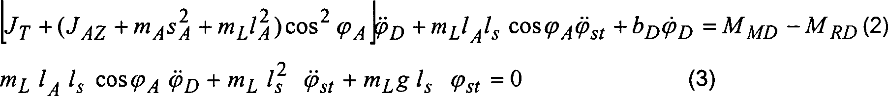
Bezeichnungen:designations:
-
- mL m L
- Lastmasseload mass
- lS l s
- Seillängecable length
- mA m A
- Masse des AuslegersMass of the jib
- JAZ J AZ
- Massenträgheitsmoment des Auslegers bezüglich Schwerpunkt bei Drehung um HochachseMoment of inertia of the jib Focus on rotation about vertical axis
- lA l A
- Länge des AuslegersLength of the boom
- sA s A
- Schwerpunktsabstand des AuslegersGravity distance of the jib
- JT J T
- Massenträgheitsmoment des TurmesMoment of inertia of the tower
- bD b D
- viskose Dämpfung im Antriebviscous damping in the drive
- MMD M MD
- Antriebsmomentdrive torque
- MRD M RD
- Reibmomentfriction
(2) beschreibt im wesentlichen die Bewegungsgleichung für den Kranturm mit Ausleger, wobei die Rückwirkung durch die Lastpendelung berücksichtigt wird. (3) ist die Bewegungsgleichung, welche die Lastpendelung um den Winkel φSt beschreibt, wobei die Anregung der Lastpendelung durch die Drehung des Turmes über die Winkelbeschleunigung des Turmes oder eine äußere Störung, ausgedrückt durch Anfangsbedingungen für diese Differentialgleichungen, verursacht wird.(2) essentially describes the equation of motion for the crane tower with boom, taking into account the feedback caused by the load oscillation. (3) is the equation of motion which describes the load oscillation by the angle φ St , the excitation of the load oscillation being caused by the rotation of the tower via the angular acceleration of the tower or an external disturbance expressed by initial conditions for these differential equations.
Der hydraulische Antrieb wird durch die folgenden Gleichungen beschrieben.Of the hydraulic drive is described by the following equations.
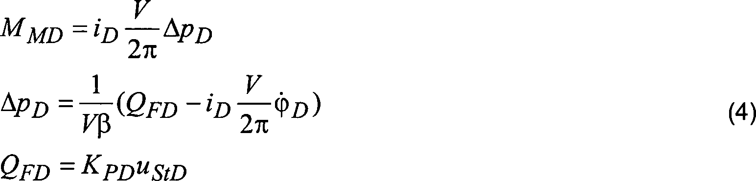
iD ist das Übersetzungsverhältnis zwischen Motordrehzahl und Drehgeschwindigkeit des Turms, V ist das Schluckvolumen der Hydraulikmotoren, ΔpD ist der Druckabfall über dem hydraulischen Antriebsmotor, β ist die Ölkompressibilität, QFD ist der Förderstrom im Hydraulikkreis für das Drehen und KPD ist die Proportionalitätskonstante, die den Zusammenhang zwischen Förderstrom und Ansteuerspannung des Proportionalventils angibt. Dynamische Effekte der unterlagerten Förderstromregelung werden vernachlässigt.i D is the gear ratio between engine speed and tower rotation speed, V is the displacement of the hydraulic motors, Δp D is the pressure drop across the hydraulic drive motor, β is the oil compressibility, Q FD is the flow rate in the hydraulic circuit for turning and K PD is the proportionality constant indicating the relationship between the flow rate and the drive voltage of the proportional valve. Dynamic effects of subordinate flow control are neglected.
Alternativ
hierzu kann das Übertragungsverhalten
der Antriebsaggregate anstatt mit der Gleichung 4 durch einen approximativen
Zusammenhang als Verzögerungsglied
1. oder höherer
Ordnung dargestellt werden. Im folgenden ist die Approximation mit
einem Verzögerungsglied
1.Ordnung dargestellt. Danach ergibt sich die ![]()
![]()
![]()
![]()
Damit kann aus den Gleichungen (6) und (3) ebenfalls eine adäquate Modellbeschreibung aufgebaut werden. TAntr ist die approximative (aus Messungen ermittelte Zeitkonstante zur Beschreibung des Verzögerungsverhaltens der Antriebe. KPDAntr die resultiertende Verstärkung zwischen Ansteuerspannung un resultierender Geschwindigkeit im stationären Fall.Thus, an adequate model description can also be constructed from equations (6) and (3). T Antr is the approximate time constant (derived from measurements to describe the deceleration behavior of the drives) K PDAntr the resulting gain between drive voltage and resulting velocity in the stationary case.
Bei
einer unerheblichen Zeitkonstante bezüglich der Antriebsdynamik kann
direkt eine Proportionalität zwischen
Geschwindigkeit und Ansteuerspannung des Proportionalventils angenommen
werden.
Auch hier kann dann aus den Gleichungen (7) und (3) eine adäquate Modellbeschreibung aufgebaut werden.Also Here, then, from the equations (7) and (3) an adequate model description being constructed.
Für die in
Das dynamische System kann dann nach Anwendung des Newton-Eulerverfahrens durch die folgenden Differentialgleichungen beschrieben werden.The dynamic system can then after applying the Newton-Eulersfahren are described by the following differential equations.

Bezeichnungen:designations:
-
- mL m L
- Lastmasseload mass
- lS l s
- Seillängecable length
- mA m A
- Masse des AuslegersMass of the jib
- JAY J AY
- Massenträgheitsmoment bezüglich Schwerpunkt bei Drehung um horizontale Achse inkl. AntriebsstrangMoment of inertia in terms of Focus on rotation about horizontal axis incl. Drive train
- lA l A
- Länge des AuslegersLength of the boom
- sA s A
- Schwerpunktsabstand des AuslegersGravity distance of the jib
- bA b A
- viskose Dämpfungviscous damping
- MMA MA
- Antriebsmomentdrive torque
- MRA M RA
- Reibmomentfriction
Gleichung (9) beschreibt im wesentlichen die Bewegungsgleichung des Auslegers mit dem antreibenden Hydraulikzylinder, wobei die Rückwirkung durch die Pendelung der Last berücksichtigt wird. Dabei ist auch der durch die Schwerkraft des Auslegers einwirkende Anteil und die viskose Reibung im Antrieb berücksichtigt. Gleichung (10) ist die Bewegungsgleichung, welche die Lastpendelung φSr beschreibt, wobei die Anregung der Schwingung durch das Aufrichten bzw. Neigen des Auslegers über die Winkelbeschleunigung des Auslegers oder eine äußere Störung, ausgedrückt durch Anfangsbedingungen für diese Differentialgleichungen, verursacht wird. Über den Term auf der rechten Seite der Differentialgleichung wird der Einfluß der Zentripetalkraft auf die Last bei Drehung der Last mit dem Drehwerk beschrieben. Dadurch wird ein für einen Drehkran typisches Problem beschrieben, da damit eine Kopplung zwischen Drehwerk und Wippwerk besteht. Anschaulich kann man dieses Problem dadurch beschreiben, daß eine Drehwerksbewegung mit quadratischer Drehgeschwindigkeitsabhängigkeit auch einen Winkelausschlag in radialer Richtung hervorruft.Equation (9) essentially describes the equation of motion of the boom with the driving hydraulic cylinder, taking into account the retroactivity of the pendulum of the load. In this case, the proportion acting through the gravity of the boom and the viscous friction in the drive is taken into account. Equation (10) is the equation of motion describing the load swing φ Sr , where the excitation of the vibration is caused by the canting of the cantilever over the angular acceleration of the cantilever or an external perturbation expressed by initial conditions for these differential equations. The term on the right side of the differential equation describes the influence of the centripetal force on the load as the load rotates with the slewing gear. As a result, a typical for a turntable problem is described, as it is a coupling between slewing and luffing. Clearly you can describe this problem in that a slewing movement with square Drehge Speed dependence also causes an angular deflection in the radial direction.
Der hydraulische Antrieb wird durch die folgenden Gleichungen beschrieben.Of the hydraulic drive is described by the following equations.
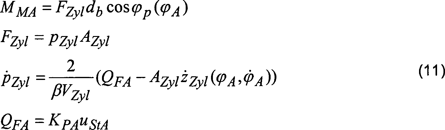
FZyl ist die Kraft des Hydraulikzylinders auf die Kolbenstange, pZyl ist der Druck im Zylinder (je nach Bewegungsrichtung kolben- oder ringseitig), AZyl ist die Querschnittsfläche des Zylinders (je nach Bewegungsrichtung kolben- oder ringseitig), β ist die Ölkompressibilität, VZyl ist das Zylindervolumen, QFA ist der Förderstrom im Hydraulikkreis für das Wippwerk und KPA ist die Proportionalitätskonstante, die den Zusammenhang zwischen Förderstrom und Ansteuerspannung des Proportionalventils angibt. Dynamische Effekte der unterlagerten Förderstromregelung werden vernachlässigt. Bei der Ölkompression im Zylinder wird als relevantes Zylindervolumen die Hälfte des Gesamtvolumens des Hydraulikzylinders angenommen. zZyl, z .Zyl sind die Position bzw. die Geschwindigkeit der Zylinderstange. Diese sind ebenso wie die geometrischen Parameter db und φp von der Aufrichtkinematik abhängig.F Zyl is the force of the hydraulic cylinder on the piston rod, p Zyl is the pressure in the cylinder (depending on the direction of movement piston or ring side), A Zyl is the cross-sectional area of the cylinder (depending on the direction of movement piston or ring side), β is the oil compressibility, V Zyl is the cylinder volume, Q FA is the flow rate in the hydraulic circuit for the luffing gear and K PA is the proportionality constant, which indicates the relationship between the flow rate and the control voltage of the proportional valve. Dynamic effects of subordinate flow control are neglected. In the oil compression in the cylinder, the relevant cylinder volume is assumed to be half the total volume of the hydraulic cylinder. z Cyl , z. Cyl are the position or speed of the cylinder rod. These, like the geometric parameters d b and φ p, are dependent on the erecting kinematics.
In
![]()
![]()
Da nur der Aufrichtwinkel φA Meßgröße ist, ist die umgekehrte Relation von (12) sowie die Abhängigkeit zwischen Kolbenstangengeschwindigkeit z .Zyl und Aufrichtgeschwindigkeit φ .A ebenfalls von Interesse.Since only the Aufrichtwinkel φ A is measured, the inverse relation of (12) and the dependence between piston rod speed z. Cyl and set-up speed φ. A also of interest.

Für die Berechnung des wirksamen Momentes auf den Ausleger ist außerdem die Berechnung des Projektionswinkels φp erforderlich.For the calculation of the effective torque on the boom, the calculation of the projection angle φ p is also required.
![]()
![]()
Für eine kompakte Notation sind in GI. 15 die Hilfsvariablen h1 und h2 eingeführt.For a compact notation are in GI. 15 introduced the auxiliary variables h 1 and h 2 .
Alternativ
kann hierzu wieder anstatt der Hydraulikgleichungen (11) eine Näherung für die Dynamik
der Antriebe mit einen approximativen Zusammenhang als Verzögerungsglied
1. oder höherer
Ordnung vorgesehen werden. Damit erhält man beispielhaft ![]()
![]()
![]()
![]()
Damit kann aus den Gleichungen (17), (14) und (10) ebenfalls eine adäquate Modellbeschreibung aufgebaut werden. TAntr ist die approximative (aus Messungen ermittelte Zeitkonstante zur Beschreibung des Verzögerungsverhaltens der Antrie be. KPAAntr die resultiertende Verstärkung zwischen Ansteuerspannung un resultierender Geschwindigkeit im stationären Fall.Thus, from the equations (17), (14) and (10) also an adequate model description can be constructed. T Antr is the approximate time constant (derived from measurements to describe the deceleration behavior of the drive) K PAAntr the resulting gain between drive voltage and resulting velocity in steady state.
Bei
einer unerheblichen Zeitkonstante bezüglich der Antriebsdynamik kann
direkt eine Proportionalität zwischen
Geschwindigkeit und Ansteuerspannung des Proportionalventils angenommen
werden.
Auch hier kann dann aus den Gleichungen (18), (10) und (14) eine adäquate Modellbeschreibung aufgebaut werden.Also Here, then, from the equations (18), (10) and (14) an adequate model description being constructed.
Letzte
Bewegungsrichtung ist das Drehen der Last am Lasthaken selbst durch
das Lastschwenkwerk. Eine entsprechende Beschreibung dieser Regelung
ergibt sich aus der deutschen Patentanmeldung
Daraus
ergibt sich die nachfolgend aufgeführte Bewegungsgleichung. Die
Varaiablenbezeichnung entsprechen der

Auch für das Lastschwenkwerk können nun Differentialgleichungen zur Beschreibung der Antriebsdynamik zur Verbesserung der Funktion wie bei der Drehbewegung zusätzlich berücksichtigt werden. Hier soll auf eine detaillierte Darstellung verzichtet werden.Also for the Can load swing mechanism now differential equations describing the drive dynamics to improve the function as in the rotational movement additionally considered become. Here should be dispensed with a detailed presentation.
Die Dynamik des Hubwerks sei vernachlässigt, da die Dynamik der Hubwerksbewegung im Vergleich zur Systemdynamik des Lastpendelung des Krans schnell ist. Wie beim Lastschwenkwerk können jedoch bei Bedarf die entsprechenden dynamischen Gleichungen zur Beschreibung der Hubwerksdynamik jederzeit ergänzt werden.The Dynamics of the hoist is neglected because the dynamics of the hoist movement Fast compared to the system dynamics of load swinging of the crane is. As with the load swing mechanism can however, if necessary, the corresponding dynamic equations for Description of the hoist dynamics can be added at any time.
Die
verbleibenden Gleichungen zur Beschreibung des Systemverhaltens
sollen nun in eine nichtlineare Zustandsraumdarstellung nach Isidori,
Nonlinear Control Systems Springer Verlag 1995 gebracht werden. Dies
sei beispielhaft basierend auf den Gleichungen (2), (3), (9), (10),
(14), (15) durchgeführt.
Dabei ist die Rotationsachse der Last um die Hochachse und die Hubwerksachse
in diesem nun nachfolgenden Beispiel nicht berücksichtigt. Es ist jedoch keine
Schwierigkeit, diese in die Modellbeschreibung mit aufzunehmen.
Für den vorliegenden
Andwendungsfall sei ein Kran ohne automatisches Lastschwenkwerk
angenommen, das Hubwerk wird vom Kranbediener manuell bedient. Dementsprechend
erhält
man: 
![]()
![]()
Die Vektoren a(x), b(x), c(x) ergeben sich durch Umformung der Gleichungen (2)–(4), (8)–(15).The vectors a (x) , b (x ), c (x) are obtained by transforming the equations (2) - (4), (8) - (15).
Im
Betrieb des Moduls zur optimierten Bewegungsführung ohne unterlagerte Lastpendeldämpfung tritt im
halbauomatischen Betrieb die Problematik auf, dass der Zustand x als Messvektor vollständig vorliegen muß. Da in
diesem Fall aber keine Pendelwinkelsensoren installiert sind, müssen die
in diesem oben beschriebenen Fall beispielhaft die Pendelwinkelgrößen φSt, φ .St, φSr, φ .Sr aus den Ansteuergrößen uStD, uStA und den Meßgrößen φD, φ .'D, φA, φ .A, pZyl rekonstruiert
werden. Hierzu wird das nichtlineare Modell nach Gleichung (20–23) linearisiert
und beispielsweise ein parameteradaptiver Zustandsbeobachter (siehe
auch
Die Sollverläufe für die Eingangssignale (Steuergrößen) uStD(t), uStA(t) werden durch die Lösung eines Optimalsteuerungsproblems, d.h. einer Aufgabe der dynamischen Optimierung bestimmt. Hierzu wird die angestrebte Reduktion des Lastpendelns in einem Zielfunktional erfasst. Randbedingungen und Trajektorienbeschränkungen des Optimalsteuerungsproblems ergeben sich aus den Bahndaten, den technischen Restriktionen des Kransystems (z.B. limitierte Antriebsleistung, sowie Beschränkungen aufgrund von dynamischer Lastmomentbegrenzungen zur Verhinderung des Kippens des Krans) sowie erweiterten Forderungen an die Bewegung der Last. Beispielsweise ist mit dem nun im folgenden beschriebenen Verfahren es erstmals möglich, den Bahnkorridor, den die Last bei der Aufschaltung der berechneten Steuerfunktionen benötigt, exakt im vorhinein zu prädizieren. Damit sind Automatisierungsmöglichkeiten gegeben, die vormals nicht lösbar waren. Eine solche Formulierung des Optimalsteuerungsproblems wird im folgenden beispielhaft sowohl für den vollautomatischen Betrieb des Systems mit vorgegebenem Start- und Zielpunkt der Lastbahn als auch für den Handhebelbetrieb gegeben.The target curves for the input signals (control variables) u StD (t), u StA (t) are determined by the solution of an optimal control problem, ie a task of the dynamic optimization. For this purpose, the desired reduction of load oscillation in a target function is recorded. Boundary conditions and trajectory constraints of the optimal control problem arise from the orbit data, the technical restrictions of the crane system (eg limited drive power, as well as limitations due to dynamic load torque limitations to prevent tilting of the crane) as well as extended demands on the movement of the load. For example, with the method now described below it is possible for the first time to predict the path corridor required by the load when connecting the calculated control functions exactly in advance. This provides automation options that were previously not solvable. Such a formulation of the optimum control problem is given below by way of example both for the fully automatic operation of the system with predetermined start and end point of the load path and for the hand lever operation.
Im Fall des vollautomatischen Betriebs wird die gesamte Bewegung vom vorgegebenem Start- bis zum vorgegebenen Zielpunkt betrachtet. Im Zielfunktional des Optimalsteuerungsproblems werden die Lastpendelwinkel quadratisch bewertet. Die Minimierung dieses Zielfunktionals liefert daher eine Bewegung mit reduzierter Lastpendelung. Eine zusätzliche Bewertung der Lastpendelwinkelgeschwindigkeiten mit einem zeitvarianten (zum Ende des Optimierungshorizonts zunehmenden) Strafterm ergibt eine Beruhigung der Lastbewegung am Ende des Optimierungshorizonts. Ein Regularisierungsterm mit quadratischer Bewertung der Amplituden der Steuergrößen kann die numerische Kondition der Aufgabe günstig beeinflussen.in the Case of fully automatic operation, the entire movement of given start to the given destination. in the The target functional of the optimal control problem becomes the load oscillation angles square rated. The minimization of this target function delivers therefore a movement with reduced load oscillation. An additional Evaluation of load pendulum angular velocities with a time variant (Increasing to the end of the optimization horizon) Strafterm results a calming of the load movement at the end of the optimization horizon. A regularization term with quadratic evaluation of the amplitudes the control variables can favorably influence the numerical condition of the task.
![]()
![]()
Bezeichnungen:designations:
-
- t0 t 0
- Vorgegebener StartzeitpunktPredetermined start time
- tf t f
- Vorgegebener EndzeitpunktPredetermined end time
- ρ(t)ρ (t)
- Zeitvarianter StrafkoeffizientTime variant penalty coefficient
- ρu(uStD,uStA)ρ u (u StD , u StA )
- Regularisierungsterm (quadratische Bewertung der Steuergrößen)regularization (quadratic evaluation of the tax variables)
Im
Handhebelbetrieb wird dagegen nicht die komplette Lastbewegung zwischen
vorgegebenem Start- und Zielpunkt betrachtet, sondern das Optimalsteuerungsproblem
wird auf einem mit dem dynamischen Vorgang mitbewegten Zeitfenster
[
Im Zielfunktional des Optimalsteuerungsproblems ist neben der angestrebten Reduktion des Lastpendelns die Abweichung der tatsächlichen Lastgeschwindigkeit von den durch die Handhebelstellungen vorgegebenen Sollgeschwindigkeiten zu berücksichtigen.in the Target functional of the optimal control problem is in addition to the desired Reduction of the load oscillation the deviation of the actual Load speed of the given by the hand lever positions To take into account target speeds.
![]()
![]()
Bezeichnungen:designations:
-
-
tt 00 - Vorgegebener Startzeitpunkt des OptimierungshorizontsPredetermined start time the optimization horizon
-
tt ff - Vorgegebener Endzeitpunkt des PrognosezeitraumsPredetermined end time of the forecast period
- ρLD ρ LD
- Bewertungskoeffizient Abweichung Lastdrehwinkelgeschwindigkeitweighting coefficient Deviation Load angular velocity
- φ .LD,soll φ. LD should
- Durch Handhebelstellung vorgegebene LastdrehwinkelgeschwindigkeitBy hand lever position predetermined load angular velocity
- ρLA ρ LA
- Bewertungskoeffizient Abweichung radiale Lastgeschwindigkeitweighting coefficient Deviation radial load speed
- r .LA,soll r. LA should
- Durch Handhebelstellung vorgegebene radiale LastgeschwindigkeitBy hand lever position predetermined radial load speed
-
Im vollautomatischen Betrieb mit vorgegebenem Start- und Zielpunkt ergeben sich die Randbedingungen für das Optimalsteuerungsproblem aus deren Koordinaten und den Anforderungen einer Ruhelage in Start und Zielposition.in the fully automatic operation with specified start and end point the boundary conditions for the optimal control problem arise from their coordinates and the requirements of a rest position in Start and Target position.
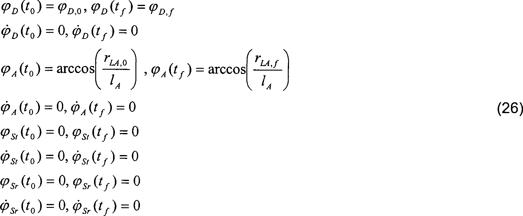
Bezeichnungen:designations:
-
- φD,0 φ D, 0
- Startpunkt DrehwerkswinkelStarting point of turning angle
- φD,f φ D, f
- Endpunkt DrehwerkswinkelEndpoint of turning angle
- rLA,0 r LA, 0
- Startpunkt LastpositionStarting point load position
- rLA,f r LA, f
- Endpunkt LastpositionEnd point load position
Die Randbedingungen für den Druck im Zylinder ergeben sich aus den stationären Werten im Start- und Zielpunkt nach Gleichung (11).The Boundary conditions for the pressure in the cylinder results from the stationary values in the start and end point according to equation (11).
Im
Handhebelbetrieb muß dagegen
in den Randbedingungen berücksichtigt
werden, dass die Bewegung nicht aus einer Ruhelage startet und im
allgemeinen auch nicht in einer Ruhelage endet. Die Randbedingungen
zum Startzeitpunkt des Optimierungshorizonts
Die
Randbedingungen am Ende des Optimierungshorizonts
Aufgrund
der technischen Parameter des Kransystems ergeben sich eine Reihe
von Restriktionen, die unabhängig
vom Betriebsmodus im Optimalsteuerungsproblem zu berücksichtigen
sind. So ist die Antriebsleistung limitiert. Dies kann über einen
maximalen Förderstrom
in den hydraulischen Antrieben beschrieben werden und über Amplitudenbeschränkungen
für die
Steuergrößen in das
Optimalsteuerungsproblem einbezogen werden.
Zur
Vermeidung von Beanspruchungen des Systems durch abrupte Lastwechsel,
deren Folgen in dem oben beschriebenen vereinfachten dynamischen
Modell nicht erfasst sind, wird die Änderungsgeschwindigkeit der
Steuergrößen limitiert.
Dadurch kann definiert die mechanische Beanspruchung limitiert.
Zusätzlich kann gefordert werden, dass die Steuergrößen als Funktionen der Zeit stetig sein sollen und stetige erste Ableitungen bezüglich der Zeit besitzen.In addition, can be required that the control variables as functions of time should be steady and steady first derivations regarding the Own time.
Der
Aufrichtwinkel ist aufgrund der Krankonstruktion limitiert
Bezeichnungen:designations:
-
- uStD,max u StD, max
- Maximalwert Ansteuerfunktion DrehwerkMaximum value control function slewing
- u .StD,max u. StD, max
- Maximale Änderungsgeschwindigkeit Ansteuerfunktion DrehwerkMaximum rate of change Control function slewing gear
- suStA,max see below StA, max
- Maximalwert Ansteuerfunktion WippwerkMaximum value control function Boom elevation
- u .StA,max u. StA, max
- Maximale Änderungsgeschwindigkeit Ansteuerfunktion WippwerkMaximum rate of change Control function Wippwerk
- φφ
- Minimalwert AufrichtwinkelMinimum value of elevation angle
- φA,max φ A, max
- Maximalwert AufrichtwinkelMaximum value of elevation angle
Zusätzliche
Restriktionen ergeben sich aus weitergehenden Anforderungen an die
Bewegung der Last. So kann beim vollautomatischen Betrieb, bei dem
die gesamte Lastbewegung vom Start- bis zum Zielpunkt betrachtet
wird, eine monotone Änderung
des Drehwinkels gefordert werden.
Bahnkorridore
lassen sich sowohl im vollautomatischen als auch im Handhebelbetrieb über die
analytische Beschreibung der zulässigen
Lastpositionen mit Hilfe von Ungleichungsrestriktionen in die Berechnung der
optimalen Steuerung einbeziehen.
Mit Hilfe dieser Ungleichungsbedingungen wird ein Bahnverlauf im Inneren eines zulässigen Bereichs, hier des Bahnkorridors erzwungen, die Grenzen dieses zulässigen Bereichs begrenzen die Lastbewegung und stellen somit ,virtuelle Wände' dar.With Help of these inequality conditions becomes a trajectory inside a permissible one Area, enforced here of the railway corridor, limits this permissible range limit the load movement and thus represent 'virtual walls'.
Besteht die abzufahrende Bahn nicht nur aus Start- und Zielpunkt, sondern sind weitere Punkte in vorgegebener Reihenfolge abzufahren, so kann das durch innere Randbedingungen in das Optimalsteuerungsproblem einbezogen werden.Consists the track to be driven not only from the start and finish point, but if more points are to be completed in a predetermined order, then so can this through inner boundary conditions in the optimal control problem be included.
![]()
![]()
Bezeichnungen:designations:
-
- ti t i
- (freier) Zeitpunkt des Erreichens des vorgegebenen Bahnpunktes i(free) time the reaching of the predetermined path point i
- φD,i φ D, i
- Drehwinkelkoordinate des vorgegebenen Bahnpunktes iDrehwinkelkoordinate the predetermined path point i
- rLA,i r LA, i
- Radiale Position des vorgegebenen Bahnpunktes iRadial position of the predetermined path point i
Der Anspruch ist nicht an eine bestimmte Methode zur numerischen Berechnung der optimalen Steuerungen gebunden. Der Anspruch bezieht sich ausdrücklich auch auf eine angenäherte Lösung der oben angegebenen Optimalsteuerungsprobleme, bei der im Hinblick auf einen reduzierten Rechenaufwand beim on-line Einsatz nur eine Lösung ausreichender (nicht maximaler) Genauigkeit ermittelt wird. Zudem kann aus Effektivitätsgründen eine Reihe der oben formulierten harten Beschränkungen (Randbedingungen oder Trajektorienungleichungsbeschränkungen) numerisch als weiche Beschränkung über eine Bewertung der Beschränkungsverletzung im Zielfunktional behandelt werden.Of the Claim is not to a specific method for numerical calculation tied to optimal controls. The claim also expressly applies to an approximate solution the optimal control problems mentioned above, in terms of on a reduced computational expenditure with on-line employment only one solution sufficient (non-maximal) accuracy is determined. moreover can for reasons of effectiveness one Series of the above formulated hard constraints (constraints or trajectory inequality constraints) numerically as a soft limit over a Evaluation of the restriction violation be treated in the target functional.
Beispielhaft soll hier jedoch die numerische Lösung mittels Mehrstufen-Steuerungsparametrisierung erläutert werden.exemplary Here, however, the numerical solution by means of multi-stage control parameterization will be explained.
Zur
näherungsweisen
numerischen Lösung
des Optimalsteuerungsproblems wird der Optimierungshorizont diskretisiert.
Die Länge der Teilintervalle [tk, tk+1] kann dabei an die Dynamik des Problems angepasst werden. Eine größere Anzahl von Teilintervallen führt in der Regel zu einer Verbesserung der Näherungslösung, aber auch zu einem erhöhten Berechnungsaufwand.The length of the subintervals [t k , t k + 1 ] can be adapted to the dynamics of the problem. A larger number of subintervals usually leads to an improvement of the approximate solution, but also to an increased calculation effort.
Auf
jedem dieser Teilintervalle wird nun der Zeitverlauf der Steuergrößen durch
eine Ansatzfunktion Uk mit einer festen
Anzahl von Parametern uk (Steuerungsparameter)
approximiert.
Nun kann die Zustandsdifferentialgleichung des dynamischen Modells numerisch integriert und das Zielfunktional ausgewertet werden, wobei anstelle der Steuergrößen die approximierten Zeitverläufe eingesetzt werden. Im Ergebnis wird das Zielfunktional als Funktion der Steuerungsparameter uk , k = 0, ..., K-1 erhalten. Die Randbedingungen und die Trajektorienbeschränkungen lassen sich ebenso als Funktionen der Steuerungsparameter auffassen.Now, the state differential equation of the dynamic model can be numerically integrated and the target functionally evaluated, whereby the approximated time profiles are used instead of the control variables. As a result, the target function is obtained as a function of the control parameters u k , k = 0, ..., K-1. The boundary conditions and the trajectory restrictions can also be understood as functions of the control parameters.
Das Optimalsteuerungsproblem wird auf diese Weise durch ein nichtlineares Optimierungsproblem in den Steuerungsparametern angenähert, wobei Zielfunktionsberechnung und Beschränkungsauswertung des nichtlinearen Optimierungsproblems jeweils die numerische Integration des dynamischen Modells unter Berücksichtigung des Approximationsansatzes nach Gleichung (34) erfordern.The Optimal control problem is this way by a nonlinear Optimization problem in the control parameters approximated, where Target function calculation and constraint evaluation of the nonlinear Optimization problem respectively the numerical integration of the dynamic Model under consideration of the approximation approach according to equation (34).
Dieses beschränkte nichtlineare Optimierungsproblem kann nun numerisch gelöst werden, wobei hierzu ein übliches Verfahren der sequentiellen quadratischen Programmierung (SQP) eingesetzt wird, bei dem die Lösung des nichtlinearen Problems über eine Folge von linear-quadratischen Näherungen bestimmt wird.This limited nonlinear optimization problem can now be solved numerically this being a common Sequential quadratic programming (SQP) method is used is where the solution of the nonlinear problem about a sequence of linear-quadratic approximations is determined.
Die
Effizienz der numerischen Lösung
kann beträchtlich
gesteigert werden, wenn zusätzlich
zu den Steuerungsparametern des Intervalls k auch noch der Anfangszustand
Als Lösung des Optimalsteuerungsproblems werden die optimalen Zeitverläufe sowohl der Steuergrößen als auch der Zustandsgrößen des dynamischen Modells erhalten. Diese werden bei Betrieb mit unterlagerter Regelung als Stell- und Führungsgrößen aufgeschaltet. Da in diesen Sollfunktionen das dynamische Verhalten des Krans berücksichtigt ist, müssen durch die Regelung nur noch Störgrößen und Modellabweichungen ausgeglichen werden.As a solution to the optimal control problem, the optimum time courses of both the control variables and the state variables of the dynamic model are obtained. These are used in operation with unterla gerter control as actuating and reference variables switched. Since the dynamic behavior of the crane is taken into account in these nominal functions, only disturbances and model deviations have to be compensated by the control.
Bei Betrieb ohne unterlagerte Regelung werden die optimalen Verläufe der Steuergrößen dagegen direkt als Stellgrößen aufgeschaltet.at Operation without subordinate control will be the optimal course of the Control variables, on the other hand directly connected as manipulated variables.
Weiterhin liefert die Lösung des Optimalsteuerungsproblems eine Prognose der Bahn der pendelnden Last, die für erweiterte Maßnahmen zur Kollisionsvermeidung nutzbar ist.Farther delivers the solution of the optimal control problem, a prognosis of the path of the oscillating load, the for extended measures is usable for collision avoidance.
Eine
einmal berechnete optimale Steuerung wird nicht über den vollen Zeithorizont
[
Claims (9)
Priority Applications (8)
| Application Number | Priority Date | Filing Date | Title |
|---|---|---|---|
| US10/510,427 US7426423B2 (en) | 2003-05-30 | 2003-05-27 | Crane or excavator for handling a cable-suspended load provided with optimised motion guidance |
| DE10324692A DE10324692A1 (en) | 2003-05-30 | 2003-05-30 | Crane or excavator for handling a load suspended on a load rope with optimized motion control |
| EP04739403A EP1628902B1 (en) | 2003-05-30 | 2004-05-27 | Crane or excavator for handling a cable-suspended load provided with optimised motion guidance |
| DE502004005274T DE502004005274D1 (en) | 2003-05-30 | 2004-05-27 | CRANE OR EXCAVATOR FOR HANDLING A LOAD HANGING ON A LOAD WITH OPTIMIZED MOTION GUIDANCE |
| JP2006508215A JP4795228B2 (en) | 2003-05-30 | 2004-05-27 | Crane or excavator with optimal movement guidance for handling rope-loaded luggage |
| KR1020057022584A KR20060021866A (en) | 2003-05-30 | 2004-05-27 | Crane or excavator for handling a cable-suspended load provided with optimised motion guidance |
| ES04739403T ES2293271T3 (en) | 2003-05-30 | 2004-05-27 | CRANE OR EXCAVATOR FOR THE TRANSFER OF A LOAD SUSPENDED FROM A LOAD CABLE WITH OPTIMIZED DISPLACEMENT GUIDE. |
| PCT/EP2004/005734 WO2004106215A1 (en) | 2003-05-30 | 2004-05-27 | Crane or excavator for handling a cable-suspended load provided with optimised motion guidance |
Applications Claiming Priority (1)
| Application Number | Priority Date | Filing Date | Title |
|---|---|---|---|
| DE10324692A DE10324692A1 (en) | 2003-05-30 | 2003-05-30 | Crane or excavator for handling a load suspended on a load rope with optimized motion control |
Publications (1)
| Publication Number | Publication Date |
|---|---|
| DE10324692A1 true DE10324692A1 (en) | 2005-01-05 |
Family
ID=33482330
Family Applications (2)
| Application Number | Title | Priority Date | Filing Date |
|---|---|---|---|
| DE10324692A Ceased DE10324692A1 (en) | 2003-05-30 | 2003-05-30 | Crane or excavator for handling a load suspended on a load rope with optimized motion control |
| DE502004005274T Expired - Lifetime DE502004005274D1 (en) | 2003-05-30 | 2004-05-27 | CRANE OR EXCAVATOR FOR HANDLING A LOAD HANGING ON A LOAD WITH OPTIMIZED MOTION GUIDANCE |
Family Applications After (1)
| Application Number | Title | Priority Date | Filing Date |
|---|---|---|---|
| DE502004005274T Expired - Lifetime DE502004005274D1 (en) | 2003-05-30 | 2004-05-27 | CRANE OR EXCAVATOR FOR HANDLING A LOAD HANGING ON A LOAD WITH OPTIMIZED MOTION GUIDANCE |
Country Status (7)
| Country | Link |
|---|---|
| US (1) | US7426423B2 (en) |
| EP (1) | EP1628902B1 (en) |
| JP (1) | JP4795228B2 (en) |
| KR (1) | KR20060021866A (en) |
| DE (2) | DE10324692A1 (en) |
| ES (1) | ES2293271T3 (en) |
| WO (1) | WO2004106215A1 (en) |
Cited By (14)
| Publication number | Priority date | Publication date | Assignee | Title |
|---|---|---|---|---|
| DE102005036848A1 (en) * | 2005-08-04 | 2007-02-22 | Siemens Ag | Method and device for motion control of a movable machine element of a machine |
| DE102005043022A1 (en) * | 2005-09-09 | 2007-03-22 | Siemens Ag | Method and / or device for controlling and / or monitoring a movement in industrial machines |
| DE102005048390A1 (en) * | 2005-10-10 | 2007-04-19 | Siemens Ag | Method and device for motion control of a movable machine element of a machine |
| EP1992583A2 (en) | 2007-05-16 | 2008-11-19 | Liebherr-Werk Nenzing GmbH | Crane control, crane and method |
| DE102007039408A1 (en) | 2007-05-16 | 2008-11-20 | Liebherr-Werk Nenzing Gmbh | Crane control system for crane with cable for load lifting by controlling signal tower of crane, has sensor unit for determining cable angle relative to gravitational force |
| EP2033931A1 (en) | 2006-10-17 | 2009-03-11 | Liebherr-Werk Nenzing GmbH | A control system for a boom crane |
| US7850025B2 (en) | 2006-07-18 | 2010-12-14 | Liebherr-Werk Nenzing Gmbh | Method for controlling the orientation of a crane load |
| DE102014008094A1 (en) * | 2014-06-02 | 2015-12-03 | Liebherr-Werk Nenzing Gmbh | Method for controlling the alignment of a crane load and a jib crane |
| DE102017114789A1 (en) | 2017-07-03 | 2019-01-03 | Liebherr-Components Biberach Gmbh | Crane and method for controlling such a crane |
| WO2020001991A1 (en) | 2018-06-26 | 2020-01-02 | Liebherr-Components Biberach Gmbh | Crane and method for controlling such a crane |
| DE202019102393U1 (en) | 2019-03-08 | 2020-06-09 | Liebherr-Werk Biberach Gmbh | Crane and device for its control |
| WO2021037526A1 (en) | 2019-08-26 | 2021-03-04 | Liebherr-Werk Biberach Gmbh | Crane and method for controlling such a crane |
| EP3912949A1 (en) | 2020-05-20 | 2021-11-24 | TenneT TSO GmbH | Lifting device and a watercraft provided with such a lifting device and working method for same |
| DE102021130785A1 (en) | 2021-11-24 | 2023-05-25 | Liebherr-Werk Biberach Gmbh | crane |
Families Citing this family (54)
| Publication number | Priority date | Publication date | Assignee | Title |
|---|---|---|---|---|
| US20040236673A1 (en) * | 2000-10-17 | 2004-11-25 | Eder Jeff Scott | Collaborative risk transfer system |
| US20080027769A1 (en) | 2002-09-09 | 2008-01-31 | Jeff Scott Eder | Knowledge based performance management system |
| US20080256069A1 (en) * | 2002-09-09 | 2008-10-16 | Jeffrey Scott Eder | Complete Context(tm) Query System |
| US20110040631A1 (en) * | 2005-07-09 | 2011-02-17 | Jeffrey Scott Eder | Personalized commerce system |
| GB0406336D0 (en) * | 2004-03-19 | 2004-04-21 | Subsea 7 Uk | Apparatus and method |
| US20090043637A1 (en) * | 2004-06-01 | 2009-02-12 | Eder Jeffrey Scott | Extended value and risk management system |
| US20060109274A1 (en) * | 2004-10-28 | 2006-05-25 | Accelerated Pictures, Llc | Client/server-based animation software, systems and methods |
| US8713025B2 (en) | 2005-03-31 | 2014-04-29 | Square Halt Solutions, Limited Liability Company | Complete context search system |
| US7970521B2 (en) * | 2005-04-22 | 2011-06-28 | Georgia Tech Research Corporation | Combined feedback and command shaping controller for multistate control with application to improving positioning and reducing cable sway in cranes |
| US7831333B2 (en) | 2006-03-14 | 2010-11-09 | Liebherr-Werk Nenzing Gmbh | Method for the automatic transfer of a load hanging at a load rope of a crane or excavator with a load oscillation damping and a trajectory planner |
| DE502006005975D1 (en) * | 2006-03-15 | 2010-03-11 | Liebherr Werk Nenzing | Method for automatically handling a load of a crane with load oscillation damping and path planner |
| JP5642326B2 (en) * | 2006-03-22 | 2014-12-17 | リープヘル−ヴェルク ネンツィング ゲーエムベーハー | A method of automatically transshipping a suspended load suspended from a suspended load rope by a crane or bagger |
| US8498915B2 (en) | 2006-04-02 | 2013-07-30 | Asset Reliance, Inc. | Data processing framework for financial services |
| WO2008014487A2 (en) * | 2006-07-28 | 2008-01-31 | Accelerated Pictures, Inc. | Scene organization in computer-assisted filmmaking |
| US7880770B2 (en) * | 2006-07-28 | 2011-02-01 | Accelerated Pictures, Inc. | Camera control |
| TWI444939B (en) * | 2008-01-10 | 2014-07-11 | Univ Nat Taiwan | A crane simulation method and system |
| US7934329B2 (en) * | 2008-02-29 | 2011-05-03 | Caterpillar Inc. | Semi-autonomous excavation control system |
| DE102009032267A1 (en) * | 2009-07-08 | 2011-01-13 | Liebherr-Werk Nenzing Gmbh, Nenzing | Crane for handling a load suspended on a load rope |
| DE102009032270A1 (en) * | 2009-07-08 | 2011-01-13 | Liebherr-Werk Nenzing Gmbh | Method for controlling a drive of a crane |
| DE102009032269A1 (en) * | 2009-07-08 | 2011-01-13 | Liebherr-Werk Nenzing Gmbh | Crane control for controlling a hoist of a crane |
| KR100963394B1 (en) * | 2010-03-19 | 2010-06-14 | 동명대학교산학협력단 | Crane control apparatus and method |
| DE102010038218B4 (en) | 2010-10-15 | 2014-02-13 | Deutsches Zentrum für Luft- und Raumfahrt e.V. | A crane having a structure with at least one actuator acting on the structure and a controller driving the actuator to suppress vibrations of the structure |
| CN102001587B (en) * | 2010-11-17 | 2012-02-15 | 武汉船用机械有限责任公司 | Automatic control method and control device for ship rotary crane jib laying |
| CN102120545B (en) * | 2010-12-22 | 2012-12-19 | 中联重科股份有限公司 | Crane anti-swing system |
| CN102502430B (en) * | 2011-11-22 | 2014-01-01 | 中联重科股份有限公司 | Crane and lifting beam thereof |
| CN102542123B (en) * | 2012-02-21 | 2013-04-10 | 长治清华机械厂 | Pressure optimization computing method for hydraulic system of arm drawing mechanism |
| DE102012004914A1 (en) * | 2012-03-09 | 2013-09-12 | Liebherr-Werk Nenzing Gmbh | Crane control with rope power mode |
| CN102826471B (en) * | 2012-09-21 | 2014-05-14 | 徐州重型机械有限公司 | Crane as well as operation safety control system and method thereof |
| CN102923577B (en) * | 2012-11-14 | 2014-12-10 | 中联重科股份有限公司 | Control method, equipment and system for slewing jib of tower crane |
| ES2676452T3 (en) | 2013-07-05 | 2018-07-19 | Liebherr-Werk Nenzing Gmbh | Crane controller |
| CN103324198B (en) * | 2013-07-08 | 2015-11-25 | 宁波江东晟创工业产品设计有限公司 | A kind of truck positioning automated induction systems based on computer vision technique and using method thereof |
| CN103723629B (en) * | 2013-12-31 | 2017-02-15 | 三一海洋重工有限公司 | Crane and anti-swing control method for steel wire rope of crane |
| US9822507B2 (en) | 2014-12-02 | 2017-11-21 | Cnh Industrial America Llc | Work vehicle with enhanced implement position control and bi-directional self-leveling functionality |
| US10384915B2 (en) * | 2015-03-19 | 2019-08-20 | Tadano Ltd. | Pivoting device |
| CN105334870B (en) * | 2015-10-31 | 2018-07-13 | 长治清华机械厂 | A kind of torque arm device multiple target mechanism optimization method |
| JP6772803B2 (en) * | 2016-12-09 | 2020-10-21 | 株式会社タダノ | crane |
| KR101875870B1 (en) * | 2016-12-30 | 2018-07-06 | 금원엔지니어링(주) | Wire-weaving setting method of rope balanced type horizontal inlet crane |
| CN107014902A (en) * | 2017-04-12 | 2017-08-04 | 河北大学 | A kind of wind electricity blade detection means and its detection method |
| JP7082477B2 (en) | 2017-11-22 | 2022-06-08 | 古河機械金属株式会社 | Controls, control methods and programs |
| NL2021043B1 (en) | 2018-06-01 | 2019-12-10 | Itrec Bv | Offshore wind turbine installation vessel and a crane for providing such a vessel and method for upending a monopile |
| US20210047153A1 (en) * | 2018-03-19 | 2021-02-18 | Tadano Ltd. | Crane and crane control method |
| EP3566998B1 (en) * | 2018-05-11 | 2023-08-23 | ABB Schweiz AG | Control of overhead cranes |
| EP3802395A4 (en) * | 2018-05-30 | 2022-03-16 | Syracuse Ltd. | System and method for transporting a swaying hoisted load |
| JP7151223B2 (en) * | 2018-07-09 | 2022-10-12 | 株式会社タダノ | Cranes and crane control methods |
| JP7172243B2 (en) * | 2018-07-25 | 2022-11-16 | 株式会社タダノ | Cranes and crane control systems |
| JP7172256B2 (en) * | 2018-07-31 | 2022-11-16 | 株式会社タダノ | crane |
| CN108975166B (en) * | 2018-08-29 | 2020-07-03 | 微特技术有限公司 | Weighing method based on variable-amplitude steel wire rope force taking |
| CN109019346B (en) * | 2018-09-30 | 2023-04-25 | 武汉理工大学 | Amplitude-changing speed-regulating method and control handle of embedded intelligent crane |
| JP7247703B2 (en) * | 2019-03-27 | 2023-03-29 | 株式会社タダノ | Crane control method and crane |
| CN110407095B (en) * | 2019-06-25 | 2021-08-13 | 河南科技大学 | Bridge crane positioning anti-swing control method based on online track planning |
| JP6966108B2 (en) * | 2020-03-18 | 2021-11-10 | Totalmasters株式会社 | Positioning calibration method for construction work machines and its positioning calibration controller |
| NL2026970B1 (en) | 2020-11-24 | 2022-07-01 | Prince Lifting Devices Pld B V | Crane for handling a cable-suspended load, method of manufacturing such a crane and use of such a crane. |
| WO2022141458A1 (en) * | 2020-12-31 | 2022-07-07 | 中联重科股份有限公司 | Hoisting control method and system, and engineering machine |
| CN116639601B (en) * | 2023-07-25 | 2023-09-29 | 日照市海洋与渔业研究院(日照市海域使用动态监视监测中心、日照市水生野生动物救护站) | Lifting equipment for cultivation |
Family Cites Families (18)
| Publication number | Priority date | Publication date | Assignee | Title |
|---|---|---|---|---|
| JPS56149987A (en) * | 1980-04-22 | 1981-11-20 | Mitsubishi Electric Corp | Steady-rest controlling device for suspension type crane |
| JPS6133487A (en) * | 1984-07-20 | 1986-02-17 | 株式会社小松製作所 | Method and device for controlling bracing of mobile type crane |
| DE4025749A1 (en) | 1990-08-14 | 1992-02-20 | Siemens Ag | Automatic operation of revolving crane without load swings - involves controlled timing of grab acceleration and retardation adjusted to period of natural frequency of oscillation |
| US5526946A (en) * | 1993-06-25 | 1996-06-18 | Daniel H. Wagner Associates, Inc. | Anti-sway control system for cantilever cranes |
| FR2713557B1 (en) | 1993-12-08 | 1996-03-01 | Michelin & Cie | Rim, support ring and assembly comprising said elements. |
| DE19502421C2 (en) | 1995-01-26 | 1997-03-27 | Siemens Ag | Method and device for transporting a load |
| DE19509734A1 (en) * | 1995-03-13 | 1996-09-19 | Mannesmann Ag | Procedure for guiding a crane with luffing jib |
| JP3237557B2 (en) * | 1996-02-02 | 2001-12-10 | 日本鋼管株式会社 | Sway control method for crane hanging load |
| US5908122A (en) * | 1996-02-29 | 1999-06-01 | Sandia Corporation | Sway control method and system for rotary cranes |
| US5961563A (en) | 1997-01-22 | 1999-10-05 | Daniel H. Wagner Associates | Anti-sway control for rotating boom cranes |
| DE19920431A1 (en) | 1999-05-04 | 2000-11-16 | Hofer Eberhard | Method for damping pendulum load on cranes with reduced sensory mechanism includes one or more drive motors while detecting the cable length between a crane trolley, its load and a load mass. |
| US6442439B1 (en) * | 1999-06-24 | 2002-08-27 | Sandia Corporation | Pendulation control system and method for rotary boom cranes |
| JP4096473B2 (en) * | 1999-11-04 | 2008-06-04 | 神鋼電機株式会社 | Crane device drive control device, crane device drive control method, and recording medium |
| US6631300B1 (en) | 1999-11-05 | 2003-10-07 | Virginia Tech Intellectual Properties, Inc. | Nonlinear active control of dynamical systems |
| US6496765B1 (en) * | 2000-06-28 | 2002-12-17 | Sandia Corporation | Control system and method for payload control in mobile platform cranes |
| FI109349B (en) * | 2000-07-18 | 2002-07-15 | Timberjack Oy | Method of Boom Control and Boom Control System |
| DE10064182A1 (en) | 2000-10-19 | 2002-05-08 | Liebherr Werk Nenzing | Crane or excavator for handling a load suspended from a load rope with load swing damping |
| JP2003155192A (en) | 2001-11-16 | 2003-05-27 | Mitsubishi Heavy Ind Ltd | Method for operating crane, control system, and crane provided with the same |
-
2003
- 2003-05-27 US US10/510,427 patent/US7426423B2/en not_active Expired - Fee Related
- 2003-05-30 DE DE10324692A patent/DE10324692A1/en not_active Ceased
-
2004
- 2004-05-27 KR KR1020057022584A patent/KR20060021866A/en not_active Application Discontinuation
- 2004-05-27 EP EP04739403A patent/EP1628902B1/en not_active Expired - Fee Related
- 2004-05-27 WO PCT/EP2004/005734 patent/WO2004106215A1/en active IP Right Grant
- 2004-05-27 ES ES04739403T patent/ES2293271T3/en not_active Expired - Lifetime
- 2004-05-27 DE DE502004005274T patent/DE502004005274D1/en not_active Expired - Lifetime
- 2004-05-27 JP JP2006508215A patent/JP4795228B2/en not_active Expired - Fee Related
Cited By (28)
| Publication number | Priority date | Publication date | Assignee | Title |
|---|---|---|---|---|
| DE102005036848A1 (en) * | 2005-08-04 | 2007-02-22 | Siemens Ag | Method and device for motion control of a movable machine element of a machine |
| DE102005036848B4 (en) * | 2005-08-04 | 2007-11-22 | Siemens Ag | Method and device for motion control of a movable machine element of a machine |
| DE102005043022A1 (en) * | 2005-09-09 | 2007-03-22 | Siemens Ag | Method and / or device for controlling and / or monitoring a movement in industrial machines |
| DE102005048390A1 (en) * | 2005-10-10 | 2007-04-19 | Siemens Ag | Method and device for motion control of a movable machine element of a machine |
| US7902785B2 (en) | 2005-10-10 | 2011-03-08 | Siemens Aktiengesellschaft | Method and device for guiding the movement of a moveable machine element of a machine |
| US7850025B2 (en) | 2006-07-18 | 2010-12-14 | Liebherr-Werk Nenzing Gmbh | Method for controlling the orientation of a crane load |
| EP2033931A1 (en) | 2006-10-17 | 2009-03-11 | Liebherr-Werk Nenzing GmbH | A control system for a boom crane |
| US7850024B2 (en) | 2006-10-17 | 2010-12-14 | Liebherr-Werk Nenzing Gmbh | Control system for a boom crane |
| EP1992583A2 (en) | 2007-05-16 | 2008-11-19 | Liebherr-Werk Nenzing GmbH | Crane control, crane and method |
| DE102007039408A1 (en) | 2007-05-16 | 2008-11-20 | Liebherr-Werk Nenzing Gmbh | Crane control system for crane with cable for load lifting by controlling signal tower of crane, has sensor unit for determining cable angle relative to gravitational force |
| DE202008018260U1 (en) | 2007-05-16 | 2012-05-15 | Liebherr-Werk Nenzing Gmbh | Crane control and crane |
| EP2502871A1 (en) | 2007-05-16 | 2012-09-26 | Liebherr-Werk Nenzing GmbH | Crane control, crane and method |
| US9556006B2 (en) | 2014-06-02 | 2017-01-31 | Liebherr-Werk Nenzing Gmbh | Method for controlling the orientation of a crane load and a boom crane |
| DE102014008094A1 (en) * | 2014-06-02 | 2015-12-03 | Liebherr-Werk Nenzing Gmbh | Method for controlling the alignment of a crane load and a jib crane |
| EP2952466A1 (en) * | 2014-06-02 | 2015-12-09 | Liebherr-Werk Nenzing GmbH | Method for controlling the orientation of a crane load and a boom crane |
| DE102017114789A1 (en) | 2017-07-03 | 2019-01-03 | Liebherr-Components Biberach Gmbh | Crane and method for controlling such a crane |
| WO2019007541A1 (en) | 2017-07-03 | 2019-01-10 | Liebherr-Components Biberach Gmbh | Crane and method for controlling such a crane |
| US11987476B2 (en) | 2018-06-26 | 2024-05-21 | Liebherr-Werk Biberach Gmbh | Crane and method for controlling such a crane |
| WO2020001991A1 (en) | 2018-06-26 | 2020-01-02 | Liebherr-Components Biberach Gmbh | Crane and method for controlling such a crane |
| DE102018005068A1 (en) | 2018-06-26 | 2020-01-02 | Liebherr-Components Biberach Gmbh | Crane and method for controlling such a crane |
| DE202019102393U1 (en) | 2019-03-08 | 2020-06-09 | Liebherr-Werk Biberach Gmbh | Crane and device for its control |
| US11932517B2 (en) | 2019-03-08 | 2024-03-19 | Liebherr-Werk Biberach Gmbh | Crane and device for controlling same |
| WO2020182592A1 (en) | 2019-03-08 | 2020-09-17 | Liebherr-Werk Biberach Gmbh | Crane and device for controlling same |
| WO2021037526A1 (en) | 2019-08-26 | 2021-03-04 | Liebherr-Werk Biberach Gmbh | Crane and method for controlling such a crane |
| EP3912949A1 (en) | 2020-05-20 | 2021-11-24 | TenneT TSO GmbH | Lifting device and a watercraft provided with such a lifting device and working method for same |
| DE102020113699A1 (en) | 2020-05-20 | 2021-11-25 | TenneT TSO GmbH | Lifting device and a watercraft equipped with such a lifting device, as well as a specific working method |
| DE102021130785A1 (en) | 2021-11-24 | 2023-05-25 | Liebherr-Werk Biberach Gmbh | crane |
| WO2023094516A1 (en) | 2021-11-24 | 2023-06-01 | Liebherr-Werk Biberach Gmbh | Crane |
Also Published As
| Publication number | Publication date |
|---|---|
| JP2006525928A (en) | 2006-11-16 |
| ES2293271T3 (en) | 2008-03-16 |
| JP4795228B2 (en) | 2011-10-19 |
| DE502004005274D1 (en) | 2007-11-29 |
| KR20060021866A (en) | 2006-03-08 |
| EP1628902A1 (en) | 2006-03-01 |
| US7426423B2 (en) | 2008-09-16 |
| WO2004106215A1 (en) | 2004-12-09 |
| EP1628902B1 (en) | 2007-10-17 |
| US20060074517A1 (en) | 2006-04-06 |
Similar Documents
| Publication | Publication Date | Title |
|---|---|---|
| DE10324692A1 (en) | Crane or excavator for handling a load suspended on a load rope with optimized motion control | |
| EP1326798B1 (en) | Crane or digger for swinging a load hanging on a support cable with damping of load oscillations | |
| EP3649072B1 (en) | Crane and method for controlling such a crane | |
| EP2272784B1 (en) | Crane for covering a load suspended on a load rope | |
| EP2272785B1 (en) | Method for controlling a drive of a crane | |
| EP2272786B1 (en) | Crane control for controlling a crane's hoisting gear | |
| EP1725715B1 (en) | Method and device for damping the displacement of construction machines | |
| EP2636632B1 (en) | Crane controls with drive restriction | |
| WO2020001991A1 (en) | Crane and method for controlling such a crane | |
| DE102014008094A1 (en) | Method for controlling the alignment of a crane load and a jib crane | |
| AT520008B1 (en) | Method for damping torsional vibrations of a load-bearing element of a lifting device | |
| EP3556969A1 (en) | Concrete pump | |
| DE102006048988A1 (en) | Control system for jib crane, has jib pivotably attached to tower, where acceleration of load in radial direction is counterbalanced based on rotation of tower by rocking motion of jib dependent on rotational speed of tower | |
| DE10064182A1 (en) | Crane or excavator for handling a load suspended from a load rope with load swing damping | |
| DE4130970C2 (en) | Control system for a mine winch | |
| DE102007059491B3 (en) | Method and circuit arrangement for the pressure medium supply of at least two hydraulic consumers | |
| DE102009041662A1 (en) | System for detecting the load mass of a hanging on a hoist rope of a crane load | |
| EP2636635A1 (en) | Crane controls with rope force mode | |
| DE102012004802A1 (en) | Crane control with distribution of a kinematically limited size of the hoist | |
| EP3556967A1 (en) | Large manipulator, especially for concrete pumps | |
| EP3556968A1 (en) | Concrete pump | |
| DE102019122796A1 (en) | Crane and method of controlling such a crane | |
| EP1834920B1 (en) | Method for automatic handling of a crane load with sway damping and path control | |
| DE10029579B4 (en) | Method for orienting the load in crane installations | |
| DE60123506T2 (en) | Turntable ladder control |
Legal Events
| Date | Code | Title | Description |
|---|---|---|---|
| OP8 | Request for examination as to paragraph 44 patent law | ||
| 8131 | Rejection |