DE10315744B4 - Microphone with RF transmitter - Google Patents
Microphone with RF transmitter Download PDFInfo
- Publication number
- DE10315744B4 DE10315744B4 DE10315744A DE10315744A DE10315744B4 DE 10315744 B4 DE10315744 B4 DE 10315744B4 DE 10315744 A DE10315744 A DE 10315744A DE 10315744 A DE10315744 A DE 10315744A DE 10315744 B4 DE10315744 B4 DE 10315744B4
- Authority
- DE
- Germany
- Prior art keywords
- antenna
- circulator
- isolator
- wireless microphone
- microphone system
- Prior art date
- Legal status (The legal status is an assumption and is not a legal conclusion. Google has not performed a legal analysis and makes no representation as to the accuracy of the status listed.)
- Expired - Fee Related
Links
Classifications
-
- H—ELECTRICITY
- H04—ELECTRIC COMMUNICATION TECHNIQUE
- H04B—TRANSMISSION
- H04B1/00—Details of transmission systems, not covered by a single one of groups H04B3/00 - H04B13/00; Details of transmission systems not characterised by the medium used for transmission
- H04B1/02—Transmitters
- H04B1/04—Circuits
- H04B1/0458—Arrangements for matching and coupling between power amplifier and antenna or between amplifying stages
-
- H—ELECTRICITY
- H01—ELECTRIC ELEMENTS
- H01Q—ANTENNAS, i.e. RADIO AERIALS
- H01Q1/00—Details of, or arrangements associated with, antennas
- H01Q1/08—Means for collapsing antennas or parts thereof
- H01Q1/088—Quick-releasable antenna elements
-
- H—ELECTRICITY
- H01—ELECTRIC ELEMENTS
- H01Q—ANTENNAS, i.e. RADIO AERIALS
- H01Q1/00—Details of, or arrangements associated with, antennas
- H01Q1/12—Supports; Mounting means
- H01Q1/22—Supports; Mounting means by structural association with other equipment or articles
-
- H—ELECTRICITY
- H01—ELECTRIC ELEMENTS
- H01Q—ANTENNAS, i.e. RADIO AERIALS
- H01Q1/00—Details of, or arrangements associated with, antennas
- H01Q1/27—Adaptation for use in or on movable bodies
- H01Q1/273—Adaptation for carrying or wearing by persons or animals
-
- H—ELECTRICITY
- H04—ELECTRIC COMMUNICATION TECHNIQUE
- H04R—LOUDSPEAKERS, MICROPHONES, GRAMOPHONE PICK-UPS OR LIKE ACOUSTIC ELECTROMECHANICAL TRANSDUCERS; ELECTRIC HEARING AIDS; PUBLIC ADDRESS SYSTEMS
- H04R1/00—Details of transducers, loudspeakers or microphones
- H04R1/08—Mouthpieces; Microphones; Attachments therefor
-
- H—ELECTRICITY
- H04—ELECTRIC COMMUNICATION TECHNIQUE
- H04B—TRANSMISSION
- H04B7/00—Radio transmission systems, i.e. using radiation field
- H04B7/02—Diversity systems; Multi-antenna system, i.e. transmission or reception using multiple antennas
- H04B7/04—Diversity systems; Multi-antenna system, i.e. transmission or reception using multiple antennas using two or more spaced independent antennas
- H04B7/08—Diversity systems; Multi-antenna system, i.e. transmission or reception using multiple antennas using two or more spaced independent antennas at the receiving station
- H04B7/0802—Diversity systems; Multi-antenna system, i.e. transmission or reception using multiple antennas using two or more spaced independent antennas at the receiving station using antenna selection
Landscapes
- Engineering & Computer Science (AREA)
- Signal Processing (AREA)
- Computer Networks & Wireless Communication (AREA)
- Physics & Mathematics (AREA)
- Acoustics & Sound (AREA)
- Transmitters (AREA)
- Details Of Audible-Bandwidth Transducers (AREA)
- Transceivers (AREA)
- Variable-Direction Aerials And Aerial Arrays (AREA)
- Near-Field Transmission Systems (AREA)
Abstract
Drahtlosmikrofon-System mit daran angeschlossenen Antennen, wobei an den Antennen oder der Antenne ein Zirkulator und/oder ein HF-Isolator angeschlossen ist und der Zirkulator und/oder HF-Isolator in der Antenne integriert ist und beide eine mechanische Einheit bilden.Wireless microphone system with attached antennas, with the antennas or the Antenna is connected to a circulator and / or an RF isolator and the circulator and / or RF isolator integrated in the antenna is and both form a mechanical unit.
Description
Die Erfindung betrifft ein Drahtlosmikrofon-System.The The invention relates to a wireless microphone system.
Solche Drahtlosmikrofone werden bereits in vielfacher Weise verwendet.Such Wireless microphones are already being used in many ways.
Aus "New Products Spring 2002", 3. April 2002, "UHF Wireless Microphone Catalog 2003", veröffentlicht am 10. März 2003, ist ein UHF-Mikrofon-Transmitter bekannt, bei welchem eine Vielzahl von Frequenzen an dem Transmitter selbst eingestellt werden können. Außerdem ist es daraus bekannt HF-Zirkulatoren, -Isolatoren oder -Filter fest in HF-Sender bzw. Drahtlos-Mikrofone einzubauen, die bei einem Frequenzwechsel entsprechend ausgetauscht werden müssen. Es liegt auf der Hand, dass dieser Austausch recht aufwendig ist und oftmals auch zu schwierigen, technischen Problemen führt.From "New Products Spring 2002, April 3, 2002, "UHF Wireless Microphone Catalog 2003 ", published On the 10th of March 2003, is a UHF microphone transmitter known in which a plurality of frequencies at the transmitter can be adjusted yourself. Furthermore it is known from RF circulators, insulators or filters permanently installed in RF transmitter or wireless microphones, the at a Frequency changes must be replaced accordingly. It is obvious that this exchange is quite expensive and often leads to difficult technical problems.
Aus
Schließlich ist aus DE-A 2 226 515 ein Gehäuse für einen Mikrowellen-Zirkulator bekannt.Finally is from DE-A 2 226 515 a housing for one Microwave circulator known.
Aufgabe der vorliegenden Erfindung ist es, solche Drahtlosmikrofon-Systeme weiterzuentwickeln. Die Erfindung zielt ferner darauf ab, eine Verbesserung des Intermodulationsabstandes von HF-Sendern zu erreichen, damit mehr Sender im gleichen Frequenzband einsetzbar sind. task It is the object of the present invention to provide such wireless microphone systems further. The invention further aims to improve the Intermodulation distance of RF transmitters to achieve more Transmitter can be used in the same frequency band.
Die Aufgabe wird erfindungsgemäß mit einem Drahtlosmikrofon-System mit den Merkmalen nach Anspruch 1 gelöst. Vorteilhafte Weiterbildungen sind in den Unteransprüchen beschrieben.The Task is according to the invention with a Wireless microphone system with the features of claim 1 solved. advantageous Further developments are described in the subclaims.
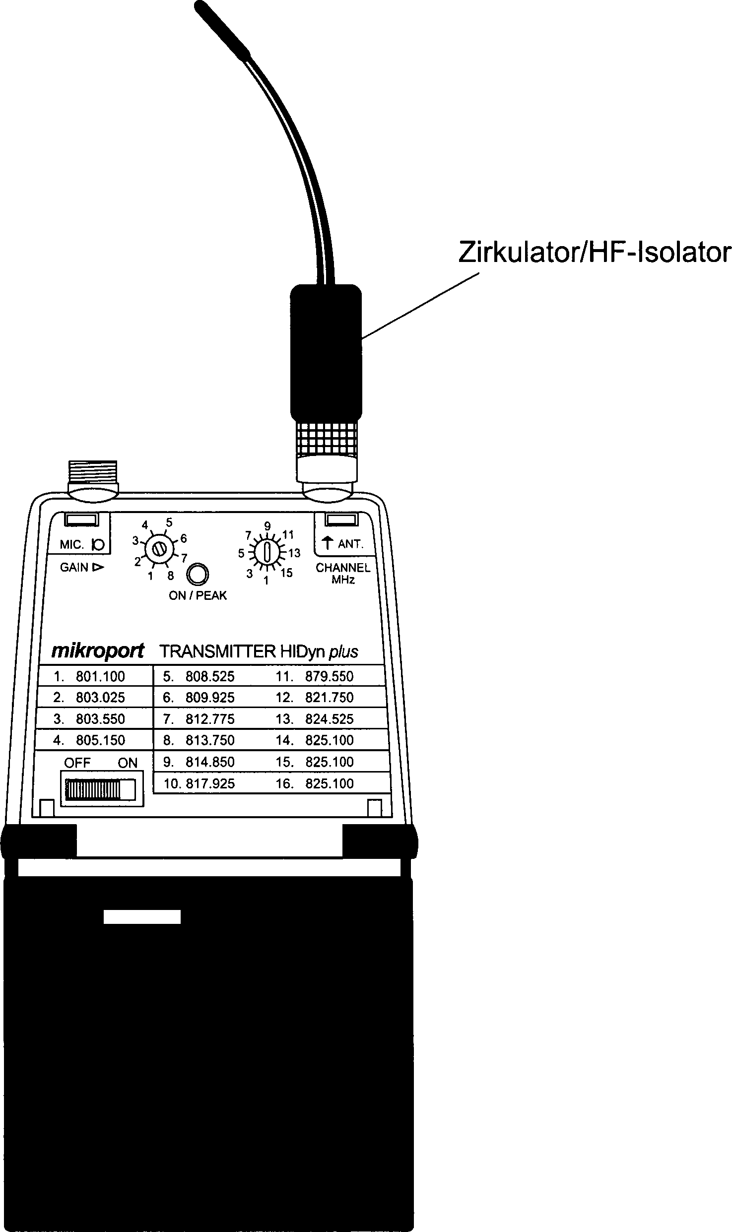
Erfindungsgemäß weisen die Antenne oder die Antennen der erfindungsgemäßen Drahtlos-Systeme einen ihr/ihnen fest zugeordneten Zirkulator/HF-Isolator auf bzw. sind mit einem solchen Zirkulator/HF-Isolator verbunden, wobei dieser Zirkulator/HF-Isolator dann auch in der Sende- oder Empfangseinrichtung selbst untergebracht sein kann. Ein besonderer Vorteil besteht jedoch darin, wenn eine Antenne steckbar an der Sende- oder Empfangseinrichtung angebracht werden kann und der Zirkulator/HF-Isolator mit in der Antenne integriert ist. Dann nämlich ist die gesamte Antenne auf einen gewünschten Bereich vorabgestimmt und braucht später nicht noch einmal gesondert eingestellt zu werden. Auch ist es von Vorteil, wenn bei einer integrierten Antenne – zum Beispiel in einem handgehaltenen drahtlosen Mikrofon (Handsender) – die Antenne mit dem Zirkulator/HF-Isolator elektrisch und mechanisch verbunden ist und diese Einheit Antenne-Zirkulator/HF-Isolator als komplette Baugruppe auswechselbar ist. Gleiches gilt für Empfangseinrichtungen.According to the invention the antenna or antennas of the wireless systems according to the invention a her / them permanently assigned circulator / RF isolator on or are with such Circulator / RF isolator connected, this circulator / RF isolator then housed in the transmitting or receiving device itself can be. A particular advantage, however, is when an antenna be plugged attached to the transmitting or receiving device can and the circulator / RF isolator integrated with the antenna is. Then that is the entire antenna is pre-tuned to a desired range and needs later not to be recruited separately. It is also from Advantage if using an integrated antenna - for example, in a handheld wireless Microphone (hand-held transmitter) - the Antenna with the circulator / HF isolator electrical and mechanical is connected and this unit antenna circulator / RF isolator as complete assembly is interchangeable. The same applies to reception facilities.
Ein Zirkulator/HF-Isolator hat regelmäßig eine geringe Durchgangsdämpfung in Sende- oder Empfangsrichtung und eine hohe Sperrdämpfung entgegen der Sende- bzw. Empfangsrichtung. Die Impedanz am Eingang des Zirkulators/HF-Isolators ist konstant und unabhängig von der Impedanz nachfolgender Komponenten. Dadurch wird bei Sendeeinrichtungen gewährleistet, dass der Sendeverstärker in einem konstanten Betriebsbereich arbeiten kann. So wird zum Beispiel bei Berührung – und damit Verstimmung – der Antenne eine geringere Rückwirkung auf den Sendeverstärker bzw. die gesamte Sendeeinrichtung auftreten. Ein wesentlicher Vorteil der Entkopplung der Antenne vom Sendeverstärker durch einen Zirkulator/HF-Isolator ist der, dass zwei benachbarte Sender sich gegenseitig nur noch gering beeinflussen; die Intermodula tion zwischen den Sendern wird stark verringert. Damit können mehrere Sendermikrofone in einem engeren Frequenzbereich störungsfrei zusammenarbeiten. Die Frequenzökonomie wird verbessert. Im umgekehrten Fall kann der Abstimmbereich, in dem die Sender arbeiten sollen, bei gleichen technischen Eigenschaften (Intermodulationsprodukte) vergrößert werden.One Circulator / HF isolator regularly has low insertion loss in Transmitting or receiving direction and a high stop attenuation against the Send or receive direction. The impedance at the input of the circulator / RF isolator is constant and independent from the impedance of subsequent components. This is at transmission facilities guaranteed that the transmission amplifier in a constant operating range can work. For example in contact - and with it Detuning - the Antenna has a lower retroactivity the transmission amplifier or the entire transmitting device occur. A significant advantage the decoupling of the antenna from the transmission amplifier by a circulator / RF isolator is that two adjacent stations are mutually exclusive low influence; the intermodulation between the stations becomes greatly reduced. With that you can several transmitter microphones in a narrower frequency range trouble-free work together. The frequency economy will be improved. In the opposite case, the tuning range, in which the transmitters should work with the same technical characteristics (Intermodulation products) are increased.
Durch die erfindungsgemäße Lösung der steckbaren/auswechselbaren mechanischen Einheit von Antenne und Zirkulator/HF-Isolator kann jedem Drahtlosmikrofon die optimale, auf den jeweiligen Arbeitsfrequenzbereich zugeordnete Antennenkombination zugeordnet werden. Dies gilt nicht nur für neu installierte Drahtlosmikrofon-Anlagen, sondern insbesondere auch für schon in Betrieb befindliche Systeme. Durch Nachrüsten von in Betrieb befindlichen Drahtlosmikrofon-Systemen kann deren Störung durch in der gleichen Anlage betriebene Nachbarkanal-Sendeanlagen deutlich reduziert werden. Im gleichen Frequenzbereich können dann zusätzliche Drahtlosmikrofone betrieben werden; dadurch steigt die Frequenzökonomie erheblich. Das ist besonders bei Drahtlosmikrofon-Systemen mit vielen Mikrofonen, zum Beispiel auf Theater-/Musical-Bühnen von Bedeutung.By the inventive solution of pluggable / interchangeable mechanical unit of antenna and circulator / HF isolator can Each wireless microphone the optimal, on the respective working frequency range associated antenna combination can be assigned. This does not apply only for newly installed wireless microphone systems, but in particular also for already in operation systems. By retrofitting In operation wireless microphone systems may be disrupted by in the same system operated adjacent channel transmitters clearly be reduced. In the same frequency range can then additional wireless microphones operate; This significantly increases the frequency economy. This is especially in wireless microphone systems with many microphones, for Example on theatrical / musical stages significant.
Weiterhin ist der Einsatz von Zirkulatoren von Bedeutung, wenn man an dem vorgegebenen Sendeverstärker eines Drahtlosmikrofons Antennen mit unterschiedlicher Richtcharakteristik betreiben will, zum Beispiel mit linearer Polarisation oder Zirkular-Polarisation. Auch hier ermöglicht der Zirkulator/HF-Isolator eine hohe Entkopplung vom Sendeverstärker und sorgt damit für einen optimalen Arbeitsbereich. Die erfindungsgemäße Lösung ermöglicht durch die mechanische Einheit von Antenne und Zirkulator/HF-Isolator eine optimale Abstimmung beider Komponenten. In der Fertigung oder nachträglich beim Anwender kann durch die steckbare/auswechselbare Einheit Antenne-Zirkulator/HF-Isolator leicht und problemlos der Frequenzbereich und/oder die Antennencharakteristik angepasst werden.Farther is the use of circulators of importance, if one at the predetermined transmission amplifier of a wireless microphone Antennas with different directional characteristics operate, for example, with linear polarization or circular polarization. Also possible here the circulator / RF isolator a high decoupling from the transmission amplifier and thus ensures a optimal workspace. The solution according to the invention made possible by the mechanical Unit of antenna and circulator / RF isolator optimal tuning both components. In the manufacturing or subsequently at the user can through the pluggable / interchangeable unit antenna-circulator / HF-isolator easy and problem-free the frequency range and / or the antenna characteristic adapted become.
Für handgehaltene Sendermikrofone (Handsender) gibt es zwei Ausführungen: Handsender mit fest angeschlossener oder aufgesteckter Antenne und Bauformen mit im Gehäuse integrierter Antenne. Für aufgesteckte Antennen gilt das gleiche wie für die eben beschriebenen Taschensender. Für Handmikrofone mit im Gehäuse integrierter Antenne ist eine Ausführungsform sinnvoll, bei der die Antenne und der Zirkulator/HF-Isolator mechanisch gemeinsam in einem separaten gemeinsamen Gehäuse untergebracht sind. Dieses wird dann bei einem Frequenzwechsel ausgetauscht.For hand-held Transmitter microphones (hand-held transmitter), there are two versions: remote control with fixed connected or plugged antenna and types with im casing integrated antenna. For plugged antennas is the same as for the bodypack transmitter just described. For handheld microphones with in the housing integrated antenna is an embodiment useful in the the antenna and the circulator / RF isolator mechanically in common housed in a separate common housing. This is then replaced with a frequency change.
Sinngemäß gelten die oben genannten Ausführungen auch für die für ein Drahtlosmikrofon-System notwendigen Empfänger. Auch hier kann die Empfängerempfindlichkeit bzw. der (Empfänger-) Intermodulationsabstand durch das Einschalten eines Zirkulators/HF-Isolators in den Hochfrequenzzweig des Empfängers verbessert werden. Auch in diesem Fall können mehr Empfänger in einem bestehenden Frequenzbereich betrieben werden, was zum oben genannten Betrieb von mehr Sendern durch Nutzung der Zirkulatoren/HF-Isolatoren im Senderausgang passt. Auch hier kann die Frequenzökonomie verbessert werden.Apply mutatis mutandis the above versions also for the for a wireless microphone system necessary receiver. Again, the receiver sensitivity or the (recipient) Intermodulation distance by switching on a circulator / HF isolator be improved in the high frequency branch of the receiver. Also in this case you can more recipients be operated in an existing frequency range, leading to the above Operation of more transmitters by using the circulators / RF isolators in the transmitter output fits. Again, the frequency economy be improved.
Auf der anderen Seite ist es mit dem Einsatz von Zirkulatoren/HF-Isolatoren im Hochfrequenzzweig der Empfänger möglich, die (abstimmbare) Empfangsfrequenzbandbreite der Empfänger wesentlich zu erweitern. Damit wird dem Anwender die Möglichkeit gegeben, sich an die am Einsatzort nutzbaren Frequenzen schnell anzupassen.On the other side is the use of circulators / RF isolators in the high-frequency branch of the receiver possible, the (tunable) receive frequency bandwidth of the receiver essential to expand. This gives the user the opportunity to get involved quickly adapt the frequencies that can be used on site.
Mit der erfindungsgemäßen Lösung der steckbaren/auswechselbaren mechanischen Einheit von (Empfangs-) Antenne-Zirkulator/HF-Isolator muss der Anwender neben dem Frequenzwechsel im Empfänger nur noch die Antennen-Zirkulator/HF-Isolator-Einheit tauschen. Damit ergibt sich eine schnelle und unkomplizierte Anpassung im aktuellen Betriebsfall.With the inventive solution of pluggable / interchangeable mechanical unit of (receiving) antenna circulator / RF isolator must the user in addition to the frequency change in the receiver only the antenna circulator / RF isolator unit To deceive. This results in a quick and easy adjustment in the current operating case.
Die oben genannten Ausführungen gelten einschließlich der in Drahtlosmikrofon-Systemen üblichen Taschenempfänger, wie sie zum Beispiel in Talkshows für die Übersetzung genutzt werden oder für Musiker als sogenannte In-Ear-Monitor-Systeme. Auch hier können durch die erfindungsgemäße Lösung durch Verringerung der Intermodulation durch die Antennen-Zirkulator/HF- Isolator-Einheit mehrere Drahtlossysteme im gleichen Frequenzbereich betrieben werden.The above versions apply including the usual in wireless microphone systems pocket receiver, such as for example in talk shows for the translation be used or for Musicians as so-called in-ear monitor systems. Also here we can by the solution according to the invention Reduction of intermodulation by the antenna circulator / RF isolator unit several wireless systems are operated in the same frequency range.
Die besonderen Vorteile der Erfindung liegen darin, dass mehr Sender als bisher in einem Frequenzband untergebracht werden können, ein Frequenzwechsel sehr einfach durchgeführt werden kann und auch bestehende HF-Sender, Sendeanlagen als auch Drahtlosmikrofone leicht nachrüstbar sind.The particular advantages of the invention are that more transmitters as previously can be accommodated in a frequency band, a Frequency changes can be done very easily and existing ones RF transmitters, transmitters as well as wireless microphones are easy to retrofit.
Die Erfindung ist nachfolgend anhand eines in Zeichnungen dargestellten Ausführungsbeispiels näher erläutert.The The invention is described below with reference to an illustrated in drawings Embodiment explained in more detail.
Soweit in der vorliegenden Anmeldung ein Drahtlosmikrofon-System beschrieben ist, gilt dies selbstverständlich nicht nur beschränkt hierauf, sondern grundsätzlich für einen HF-Sender mit einer Antenne.So far in the present application a wireless microphone system is described is, of course, this is true not just limited on this, but basically for one RF transmitter with an antenna.
Besonders vorteilhaft ist es auch, die Antenne außenseitig mit einer Kennzeichnung zu versehen, wobei diese Kennzeichnung dem jeweiligen Frequenzbereich des Zirkulators und/oder der Zirkulator-Einheit zugeordnet ist. Die Kennzeichnung kann beispielsweise aus einer Codierung bestehen oder auch aus einer Farbkennung, so dass schon aus einer gewissen Distanz sehr gut für den Fachmann, in diesem Fall ein Tontechniker oder Toningenieur, zu erkennen ist, auf welcher) Frequenz der HF-Sender des Drahtlos-Mikrofons abgestimmt ist bzw. arbeitet.Especially It is also advantageous, the antenna on the outside with a label to be provided, this marking the respective frequency range associated with the circulator and / or the circulator unit. The identification may consist of coding, for example or even from a color code, so that already from a certain Distance very good for the expert, in this case a sound engineer or sound engineer, it can be seen on which frequency the RF transmitter of the wireless microphone is coordinated or works.
Claims (12)
Priority Applications (7)
| Application Number | Priority Date | Filing Date | Title |
|---|---|---|---|
| DE10315744A DE10315744B4 (en) | 2003-04-04 | 2003-04-04 | Microphone with RF transmitter |
| JP2006504898A JP2006522516A (en) | 2003-04-04 | 2004-03-29 | Microphone with HF transmitter |
| PCT/EP2004/003298 WO2004088873A1 (en) | 2003-04-04 | 2004-03-29 | Microphone comprising an hf transmitter |
| CN200480009330.1A CN1771673B (en) | 2003-04-04 | 2004-03-29 | Microphone comprising an HF transmitter |
| US10/552,085 US20070025567A1 (en) | 2003-04-04 | 2004-03-29 | Microphone comprising an hf transmitter |
| EP04723979A EP1616396A1 (en) | 2003-04-04 | 2004-03-29 | Microphone comprising an hf transmitter |
| RU2005134217/09A RU2005134217A (en) | 2003-04-04 | 2004-03-29 | MICROPHONE WITH HF TRANSMITTER |
Applications Claiming Priority (1)
| Application Number | Priority Date | Filing Date | Title |
|---|---|---|---|
| DE10315744A DE10315744B4 (en) | 2003-04-04 | 2003-04-04 | Microphone with RF transmitter |
Publications (2)
| Publication Number | Publication Date |
|---|---|
| DE10315744A1 DE10315744A1 (en) | 2004-11-11 |
| DE10315744B4 true DE10315744B4 (en) | 2007-05-31 |
Family
ID=33103236
Family Applications (1)
| Application Number | Title | Priority Date | Filing Date |
|---|---|---|---|
| DE10315744A Expired - Fee Related DE10315744B4 (en) | 2003-04-04 | 2003-04-04 | Microphone with RF transmitter |
Country Status (7)
| Country | Link |
|---|---|
| US (1) | US20070025567A1 (en) |
| EP (1) | EP1616396A1 (en) |
| JP (1) | JP2006522516A (en) |
| CN (1) | CN1771673B (en) |
| DE (1) | DE10315744B4 (en) |
| RU (1) | RU2005134217A (en) |
| WO (1) | WO2004088873A1 (en) |
Families Citing this family (56)
| Publication number | Priority date | Publication date | Assignee | Title |
|---|---|---|---|---|
| DE102006032822A1 (en) * | 2006-07-14 | 2008-01-24 | Sennheiser Electronic Gmbh & Co. Kg | Portable mobile device |
| US8145134B2 (en) * | 2008-07-22 | 2012-03-27 | At&T Intellectual Property I, L.P. | Wireless microphone beacon |
| DE102008045112A1 (en) * | 2008-09-01 | 2010-03-04 | Sennheiser Electronic Gmbh & Co. Kg | microphone |
| DE102008045111A1 (en) * | 2008-09-01 | 2010-03-04 | Sennheiser Electronic Gmbh & Co. Kg | Antenna unit and wireless transmitting and / or receiving unit |
| US8497940B2 (en) * | 2010-11-16 | 2013-07-30 | Audio-Technica U.S., Inc. | High density wireless system |
| US10606859B2 (en) | 2014-11-24 | 2020-03-31 | Asana, Inc. | Client side system and method for search backed calendar user interface |
| EP3370302B1 (en) * | 2017-03-01 | 2024-04-24 | AKG Acoustics GmbH | Vivaldi antenna-based antennna system |
| US10977434B2 (en) | 2017-07-11 | 2021-04-13 | Asana, Inc. | Database model which provides management of custom fields and methods and apparatus therfor |
| CN107331953B (en) * | 2017-07-25 | 2019-11-19 | 富士高实业有限公司 | A wireless earphone using short-tail helical antenna and short-circuit L-shaped radiator |
| US10623359B1 (en) | 2018-02-28 | 2020-04-14 | Asana, Inc. | Systems and methods for generating tasks based on chat sessions between users of a collaboration environment |
| US11138021B1 (en) | 2018-04-02 | 2021-10-05 | Asana, Inc. | Systems and methods to facilitate task-specific workspaces for a collaboration work management platform |
| US10613735B1 (en) | 2018-04-04 | 2020-04-07 | Asana, Inc. | Systems and methods for preloading an amount of content based on user scrolling |
| US10785046B1 (en) | 2018-06-08 | 2020-09-22 | Asana, Inc. | Systems and methods for providing a collaboration work management platform that facilitates differentiation between users in an overarching group and one or more subsets of individual users |
| US10616151B1 (en) | 2018-10-17 | 2020-04-07 | Asana, Inc. | Systems and methods for generating and presenting graphical user interfaces |
| US10956845B1 (en) | 2018-12-06 | 2021-03-23 | Asana, Inc. | Systems and methods for generating prioritization models and predicting workflow prioritizations |
| US11568366B1 (en) | 2018-12-18 | 2023-01-31 | Asana, Inc. | Systems and methods for generating status requests for units of work |
| US11113667B1 (en) | 2018-12-18 | 2021-09-07 | Asana, Inc. | Systems and methods for providing a dashboard for a collaboration work management platform |
| US11782737B2 (en) | 2019-01-08 | 2023-10-10 | Asana, Inc. | Systems and methods for determining and presenting a graphical user interface including template metrics |
| US10684870B1 (en) | 2019-01-08 | 2020-06-16 | Asana, Inc. | Systems and methods for determining and presenting a graphical user interface including template metrics |
| US11204683B1 (en) | 2019-01-09 | 2021-12-21 | Asana, Inc. | Systems and methods for generating and tracking hardcoded communications in a collaboration management platform |
| US11341445B1 (en) | 2019-11-14 | 2022-05-24 | Asana, Inc. | Systems and methods to measure and visualize threshold of user workload |
| US11783253B1 (en) | 2020-02-11 | 2023-10-10 | Asana, Inc. | Systems and methods to effectuate sets of automated actions outside and/or within a collaboration environment based on trigger events occurring outside and/or within the collaboration environment |
| US11599855B1 (en) | 2020-02-14 | 2023-03-07 | Asana, Inc. | Systems and methods to attribute automated actions within a collaboration environment |
| US11763259B1 (en) | 2020-02-20 | 2023-09-19 | Asana, Inc. | Systems and methods to generate units of work in a collaboration environment |
| US11455601B1 (en) | 2020-06-29 | 2022-09-27 | Asana, Inc. | Systems and methods to measure and visualize workload for completing individual units of work |
| US11449836B1 (en) | 2020-07-21 | 2022-09-20 | Asana, Inc. | Systems and methods to facilitate user engagement with units of work assigned within a collaboration environment |
| US11568339B2 (en) | 2020-08-18 | 2023-01-31 | Asana, Inc. | Systems and methods to characterize units of work based on business objectives |
| US11769115B1 (en) | 2020-11-23 | 2023-09-26 | Asana, Inc. | Systems and methods to provide measures of user workload when generating units of work based on chat sessions between users of a collaboration environment |
| US11405435B1 (en) | 2020-12-02 | 2022-08-02 | Asana, Inc. | Systems and methods to present views of records in chat sessions between users of a collaboration environment |
| US11694162B1 (en) | 2021-04-01 | 2023-07-04 | Asana, Inc. | Systems and methods to recommend templates for project-level graphical user interfaces within a collaboration environment |
| US11676107B1 (en) | 2021-04-14 | 2023-06-13 | Asana, Inc. | Systems and methods to facilitate interaction with a collaboration environment based on assignment of project-level roles |
| US11553045B1 (en) | 2021-04-29 | 2023-01-10 | Asana, Inc. | Systems and methods to automatically update status of projects within a collaboration environment |
| US11803814B1 (en) | 2021-05-07 | 2023-10-31 | Asana, Inc. | Systems and methods to facilitate nesting of portfolios within a collaboration environment |
| US11792028B1 (en) | 2021-05-13 | 2023-10-17 | Asana, Inc. | Systems and methods to link meetings with units of work of a collaboration environment |
| US12141756B1 (en) | 2021-05-24 | 2024-11-12 | Asana, Inc. | Systems and methods to generate project-level graphical user interfaces within a collaboration environment |
| US11809222B1 (en) | 2021-05-24 | 2023-11-07 | Asana, Inc. | Systems and methods to generate units of work within a collaboration environment based on selection of text |
| US12093859B1 (en) | 2021-06-02 | 2024-09-17 | Asana, Inc. | Systems and methods to measure and visualize workload for individual users |
| US12182505B1 (en) | 2021-06-10 | 2024-12-31 | Asana, Inc. | Systems and methods to provide user-generated project-level graphical user interfaces within a collaboration environment |
| US12255390B2 (en) | 2021-08-24 | 2025-03-18 | Shure Acquisition Holdings, Inc. | Microphone antenna for wireless microphone applications |
| US11756000B2 (en) | 2021-09-08 | 2023-09-12 | Asana, Inc. | Systems and methods to effectuate sets of automated actions within a collaboration environment including embedded third-party content based on trigger events |
| US12159262B1 (en) | 2021-10-04 | 2024-12-03 | Asana, Inc. | Systems and methods to provide user-generated graphical user interfaces within a collaboration environment |
| US11635884B1 (en) | 2021-10-11 | 2023-04-25 | Asana, Inc. | Systems and methods to provide personalized graphical user interfaces within a collaboration environment |
| US12536503B1 (en) | 2021-12-06 | 2026-01-27 | Asana, Inc. | Systems and methods to track and present navigation through records of a collaboration environment |
| US12093896B1 (en) | 2022-01-10 | 2024-09-17 | Asana, Inc. | Systems and methods to prioritize resources of projects within a collaboration environment |
| US12118514B1 (en) | 2022-02-17 | 2024-10-15 | Asana, Inc. | Systems and methods to generate records within a collaboration environment based on a machine learning model trained from a text corpus |
| US11997425B1 (en) | 2022-02-17 | 2024-05-28 | Asana, Inc. | Systems and methods to generate correspondences between portions of recorded audio content and records of a collaboration environment |
| US12190292B1 (en) | 2022-02-17 | 2025-01-07 | Asana, Inc. | Systems and methods to train and/or use a machine learning model to generate correspondences between portions of recorded audio content and work unit records of a collaboration environment |
| US11836681B1 (en) | 2022-02-17 | 2023-12-05 | Asana, Inc. | Systems and methods to generate records within a collaboration environment |
| US12051045B1 (en) | 2022-04-28 | 2024-07-30 | Asana, Inc. | Systems and methods to characterize work unit records of a collaboration environment based on stages within a workflow |
| US12288171B1 (en) | 2022-07-18 | 2025-04-29 | Asana, Inc. | Systems and methods to provide records for new users of a collaboration environment |
| US12412156B1 (en) | 2022-07-21 | 2025-09-09 | Asana, Inc. | Systems and methods to characterize work unit records of a collaboration environment based on freeform arrangement of visual content items |
| US12249774B2 (en) | 2022-07-25 | 2025-03-11 | Shure Acquisition Holdings, Inc. | Dual band plug-on transmitter antenna |
| US11863601B1 (en) | 2022-11-18 | 2024-01-02 | Asana, Inc. | Systems and methods to execute branching automation schemes in a collaboration environment |
| US12287849B1 (en) | 2022-11-28 | 2025-04-29 | Asana, Inc. | Systems and methods to automatically classify records managed by a collaboration environment |
| US12401655B1 (en) | 2023-04-24 | 2025-08-26 | Asana, Inc. | Systems and methods to manage access to assets of a computer environment based on user and asset grouping |
| US12423121B1 (en) | 2023-11-09 | 2025-09-23 | Asana, Inc. | Systems and methods to customize a user interface of a collaboration environment based on ranking of work unit records managed by the collaboration environment |
Citations (2)
| Publication number | Priority date | Publication date | Assignee | Title |
|---|---|---|---|---|
| DE2226515A1 (en) * | 1972-05-31 | 1973-12-13 | Philips Patentverwaltung | HOUSING FOR A MICROWAVE CIRCULATOR |
| US4430619A (en) * | 1981-12-31 | 1984-02-07 | Motorola, Inc. | Adaptive radio frequency intermodulation minimizing apparatus |
Family Cites Families (16)
| Publication number | Priority date | Publication date | Assignee | Title |
|---|---|---|---|---|
| US4910795A (en) * | 1987-06-11 | 1990-03-20 | Mccowen Clinton R | Wireless hand held microphone |
| CA2049597A1 (en) * | 1990-09-28 | 1992-03-29 | Clifton Quan | Dielectric flare notch radiator with separate transmit and receive ports |
| JPH0870262A (en) * | 1994-08-29 | 1996-03-12 | Nec Corp | Mobile communication equipment |
| JP2768439B2 (en) * | 1994-11-08 | 1998-06-25 | 本田技研工業株式会社 | FM-CW type multi-beam radar device |
| US5701595A (en) * | 1995-05-04 | 1997-12-23 | Nippondenso Co., Ltd. | Half duplex RF transceiver having low transmit path signal loss |
| US5721783A (en) * | 1995-06-07 | 1998-02-24 | Anderson; James C. | Hearing aid with wireless remote processor |
| US5793331A (en) * | 1995-08-31 | 1998-08-11 | Lucent Technologies Inc. | User replaceable flexible retractable antenna |
| JP3007857B2 (en) * | 1997-03-19 | 2000-02-07 | 三菱電機株式会社 | Portable information devices |
| US6401040B1 (en) * | 1999-07-06 | 2002-06-04 | Conus Communications | Antenna recommendation map |
| US6469658B2 (en) * | 2000-05-26 | 2002-10-22 | Donald E. Voss | Method for creation of planar or complex wavefronts in close proximity to a transmitter array |
| JP3589952B2 (en) * | 2000-06-20 | 2004-11-17 | 松下電器産業株式会社 | Communication system and communication method thereof, wireless microphone communication system, wireless microphone, and wireless microphone receiving device |
| US6928170B1 (en) * | 2000-11-02 | 2005-08-09 | Audio Technica, Inc. | Wireless microphone having a split-band audio frequency companding system that provides improved noise reduction and sound quality |
| FI20002882A7 (en) * | 2000-12-29 | 2002-06-30 | Nokia Corp | Arrangement for fitting the antenna |
| JP4197581B2 (en) * | 2001-02-28 | 2008-12-17 | 富士通株式会社 | Information processing device |
| JP4655438B2 (en) * | 2001-09-04 | 2011-03-23 | ミツミ電機株式会社 | Antenna device |
| JP3886775B2 (en) * | 2001-10-31 | 2007-02-28 | 松下電器産業株式会社 | Wireless microphone system |
-
2003
- 2003-04-04 DE DE10315744A patent/DE10315744B4/en not_active Expired - Fee Related
-
2004
- 2004-03-29 EP EP04723979A patent/EP1616396A1/en not_active Withdrawn
- 2004-03-29 US US10/552,085 patent/US20070025567A1/en not_active Abandoned
- 2004-03-29 WO PCT/EP2004/003298 patent/WO2004088873A1/en not_active Ceased
- 2004-03-29 RU RU2005134217/09A patent/RU2005134217A/en not_active Application Discontinuation
- 2004-03-29 JP JP2006504898A patent/JP2006522516A/en active Pending
- 2004-03-29 CN CN200480009330.1A patent/CN1771673B/en not_active Expired - Fee Related
Patent Citations (2)
| Publication number | Priority date | Publication date | Assignee | Title |
|---|---|---|---|---|
| DE2226515A1 (en) * | 1972-05-31 | 1973-12-13 | Philips Patentverwaltung | HOUSING FOR A MICROWAVE CIRCULATOR |
| US4430619A (en) * | 1981-12-31 | 1984-02-07 | Motorola, Inc. | Adaptive radio frequency intermodulation minimizing apparatus |
Non-Patent Citations (1)
| Title |
|---|
| Katalog der Fa. Lectrosonics Inc., USA: UHF Wireless Microphone Catalog 03/03, S. 4 * |
Also Published As
| Publication number | Publication date |
|---|---|
| EP1616396A1 (en) | 2006-01-18 |
| JP2006522516A (en) | 2006-09-28 |
| CN1771673B (en) | 2011-09-21 |
| CN1771673A (en) | 2006-05-10 |
| DE10315744A1 (en) | 2004-11-11 |
| US20070025567A1 (en) | 2007-02-01 |
| WO2004088873A1 (en) | 2004-10-14 |
| RU2005134217A (en) | 2006-07-10 |
Similar Documents
| Publication | Publication Date | Title |
|---|---|---|
| DE10315744B4 (en) | Microphone with RF transmitter | |
| EP0484454B1 (en) | Transmitting and receiving arrangement for portable appliances | |
| DE4322863C2 (en) | Cellular antenna system | |
| DE69317235T2 (en) | Broadband antenna with associated transceiver that takes up little space | |
| DE3127566C2 (en) | Antenna matching device for a high-frequency transmitter operating according to the frequency hopping method | |
| WO2002043182A1 (en) | Pifa antenna device for mobile communication terminals | |
| DE19836952A1 (en) | Sending and receiving device | |
| EP1454381A1 (en) | Wide band slot cavity antenna | |
| DE10319248A1 (en) | Slip ring with lossy conductor track | |
| DE1766616A1 (en) | Messaging system | |
| EP4133607B1 (en) | Coupling device for wireless data and energy transfer, and coupling system for wireless data and energy transfer | |
| DE19961237A1 (en) | Antenna for radiation and reception of electromagnetic waves | |
| EP1371143B1 (en) | Circuit arrangement for compensation of the damping in an antenna feed cable for a mobile radio device | |
| EP1139491A2 (en) | Radiating coaxial high-frequency cable | |
| WO2004088865A1 (en) | Circuit arrangement for a communication terminal with a multi-mode operation | |
| EP1511117A1 (en) | Antenna system and transmitting device with such an antenna | |
| DE102018105153B4 (en) | notch filter arrangement | |
| WO2008014762A1 (en) | Inverted f-antenna | |
| EP1515393B1 (en) | Dual-band antenna for DVB-T reception | |
| DE202016103828U1 (en) | Switching device of a radio receiver for single reception of two radio signal sources or for double reception from a single radio signal source | |
| DE3036999A1 (en) | Inductive loop radio system for underground vehicle - has portable transceiver aerial inductively coupled to aerial on exterior of vehicle | |
| DE10012200A1 (en) | Wireless proximity sensor used in automation system, has directional beam antenna for transmitting/receiving radio signal to/from base station | |
| DE10202757B4 (en) | antenna device | |
| EP0094667B1 (en) | Antenna system for a secondary radar transponder | |
| DE20207401U1 (en) | Receiving device for digital high-frequency signals with a receiving antenna |
Legal Events
| Date | Code | Title | Description |
|---|---|---|---|
| OP8 | Request for examination as to paragraph 44 patent law | ||
| 8364 | No opposition during term of opposition | ||
| R119 | Application deemed withdrawn, or ip right lapsed, due to non-payment of renewal fee |