EP0484454B1 - Transmitting and receiving arrangement for portable appliances - Google Patents
Transmitting and receiving arrangement for portable appliances Download PDFInfo
- Publication number
- EP0484454B1 EP0484454B1 EP90913383A EP90913383A EP0484454B1 EP 0484454 B1 EP0484454 B1 EP 0484454B1 EP 90913383 A EP90913383 A EP 90913383A EP 90913383 A EP90913383 A EP 90913383A EP 0484454 B1 EP0484454 B1 EP 0484454B1
- Authority
- EP
- European Patent Office
- Prior art keywords
- antenna
- shielding housing
- angled
- arrangement according
- resonators
- Prior art date
- Legal status (The legal status is an assumption and is not a legal conclusion. Google has not performed a legal analysis and makes no representation as to the accuracy of the status listed.)
- Expired - Lifetime
Links
Images


Classifications
-
- H—ELECTRICITY
- H01—ELECTRIC ELEMENTS
- H01Q—ANTENNAS, i.e. RADIO AERIALS
- H01Q9/00—Electrically-short antennas having dimensions not more than twice the operating wavelength and consisting of conductive active radiating elements
- H01Q9/04—Resonant antennas
- H01Q9/0407—Substantially flat resonant element parallel to ground plane, e.g. patch antenna
- H01Q9/0421—Substantially flat resonant element parallel to ground plane, e.g. patch antenna with a shorting wall or a shorting pin at one end of the element
-
- H—ELECTRICITY
- H01—ELECTRIC ELEMENTS
- H01Q—ANTENNAS, i.e. RADIO AERIALS
- H01Q1/00—Details of, or arrangements associated with, antennas
- H01Q1/12—Supports; Mounting means
- H01Q1/22—Supports; Mounting means by structural association with other equipment or articles
- H01Q1/24—Supports; Mounting means by structural association with other equipment or articles with receiving set
- H01Q1/241—Supports; Mounting means by structural association with other equipment or articles with receiving set used in mobile communications, e.g. GSM
- H01Q1/242—Supports; Mounting means by structural association with other equipment or articles with receiving set used in mobile communications, e.g. GSM specially adapted for hand-held use
- H01Q1/243—Supports; Mounting means by structural association with other equipment or articles with receiving set used in mobile communications, e.g. GSM specially adapted for hand-held use with built-in antennas
-
- H—ELECTRICITY
- H01—ELECTRIC ELEMENTS
- H01Q—ANTENNAS, i.e. RADIO AERIALS
- H01Q19/00—Combinations of primary active antenna elements and units with secondary devices, e.g. with quasi-optical devices, for giving the antenna a desired directional characteristic
- H01Q19/005—Patch antenna using one or more coplanar parasitic elements
Definitions
- the invention relates to a transmitting and / or receiving arrangement for portable devices, consisting of a shielding housing containing the high-frequency part made of metal and an antenna, the antenna consisting of two or more radiation-coupled and essentially longitudinally oriented antenna resonators, each with a free resonator end and each have an end angled over a kink edge and conductively connected to the shielding housing.
- EP-A 177 362 describes a broadband antenna for portable radio devices. It consists of two angled resonators with different resonance frequencies. Both resonators are fed from a common line via a branch in the manner of an "inverted-F antenna". The antenna resonators work independently of one another and do not form a unit. The efficiency is therefore not particularly high. The distance between the parallel legs is constant.
- GB-A 2 067 842 describes a microstrip antenna which is applied to an insulating mass. The distance between the two antenna resonators is also constant here. The free ends of the resonators face each other. The feed point is near the free end of a resonator.
- "Inverted-F antennas” are from T. Taga and K. Tsunekawa, "Performance Analysis of a Built-In Planar Inverted F Antenna for 800 MHz Band Portable Radio Units," IEEE Trans., Selected Areas in Commun., Vol. SAC-5, no.5, pp. 921-929, June (1987). Such antennas are adapted by varying the position of the feed point.
- the invention has for its object to improve the transmission or reception performance of the antenna, wherein easy to manufacture and good adaptability should be ensured with a wide bandwidth.
- a transmitting and / or receiving arrangement for portable devices consisting of a shielding housing containing the high-frequency part made of metal and an antenna, the antenna consisting of two or more radiation-coupled and essentially longitudinally oriented antenna resonators, each with one free resonator end and one end angled via a kink edge and conductively connected to the shielding housing, the transmitter output or receiver input, possibly via a duplex filter, being connected by a coaxial feedthrough in the shielding housing via a feed line only to the feed point of a single antenna resonator, which Feed point lies between the kink edge and the free resonator end of this single antenna resonator, and wherein for varying the input impedance of the antenna the clear width of the g between two adjacent antenna resonators e formed slot in the area of the free resonator end is considerably smaller than at the kink edge.
- the non-powered resonators of the antenna are excited in a radiation-coupled manner by the powered resonator, which increases the bandwidth of the antenna. Due to the angled shape and the widening of the ends, currents flow in all three spatial directions. High cross currents form, the require a small impedance. This fills gaps in the directional characteristics of the antenna. Due to the small space requirement, the arrangement is excellently suitable for mobile radio applications. It is easy to manufacture and the entire high-frequency, low-frequency and digital electronics of a portable radio can be accommodated in the shielding housing.
- the metal housing also serves as an earth replica for the antenna.
- the range of variation is particularly large by changing the attachment point of the feed line to the antenna resonator and by virtue of the fact that the resonators are widened in the region of their ends in order to vary the input impedance of the antenna. Therefore, in many applications, adaptation networks between the antenna and the transmission output stage or transmission filter, and between the antenna and the receiver input or reception filter can be saved.
- the arrangement of the antenna resonators, which are essentially parallel to one another, can also be described as a slot antenna, the width and shape of the slot between the resonators allowing the input impedance to be varied within wide limits.
- a transmitting and receiving arrangement for portable devices consisting of a shielding housing containing the high-frequency part made of metal and an antenna, the antenna consisting of two or more radiation-coupled and essentially longitudinally oriented antenna resonators each with There is a free resonator end and one end angled via a kink edge and conductively connected to the shielding housing, the transmitter output and the receiver input each being connected to the feed point of another antenna resonator via a transmission filter or reception filter by a coaxial feedthrough in the shield housing via a feed line in each case Which feed point is located between the kink edge and the free resonator end of the respective antenna resonator, and where to vary the input impedance of the antenna, the clear width of the two adjacent antenna resonators formed slot in the area of the free resonator end is considerably smaller than at the kink edge.
- a partial decoupling of transmitter output and receiver input is achieved by feeding two antenna resonators and connecting the feed lines to the transmission and reception filters.
- separate optimization of transmitter and receiver adaptation is possible.
- the antenna can be located above any side surface of the shielding housing. In tests, however, it has proven to be advantageous for the antenna resonators to be arranged on the top or top surface of the shielding housing.
- the antenna is constructed from at least two fed, opposing partial antennas, each of which consists of two or more antenna resonators coupled to one another and essentially identically oriented (FIG. 4). Both sub-antennas can be of the same length, creating double resonance.
- the antenna consists of lambda / 4 resonators. Therefore, the bandwidth can be increased even further if the length of the antenna resonators is unequal.
- the angled antenna resonators are formed from sheet metal angles.
- three sheet metal angles are present and the middle sheet metal angle is connected to the feed line.
- the shielding housing and the sheet metal angles are punched out of a flat sheet metal and bent into the corresponding shape. But it is also possible that the sheet metal brackets are soldered to the shield housing.
- the mechanical strength of the antenna is increased by the fact that the sheet metal angles have a U-shaped longitudinal section and the non-powered or radiation-coupled leg is conductively attached to a board protruding from the shielding housing and is connected to the shielding housing via a ground plane.
- a particular stiffness is achieved in that the circuit board protrudes between the free resonator ends of the sheet metal angles and the resonator ends are connected to the circuit board.
- a special mechanical resistance is given by the fact that the shielding housing is surrounded by a plastic housing, on which the sheet metal angle as a metal foil on the outside or applied inside and connected to the shielding housing via a ground leadthrough.
- the angled antenna resonators are formed from wire angles. These wire angles converge in such a way that their free resonator ends are only a short distance apart. Here, too, high currents flow and there is a low impedance.
- the "inverted-F structure” has the advantage over the "inverted-L structure” of a higher quality of adaptation to the broadband. The improvement is about 50-100%.
- antennas with two or more angled resonators are described which can be installed in portable radio devices, such as cordless telephones, mobile telephones, pagers, “telepoint devices” etc.
- portable radio devices such as cordless telephones, mobile telephones, pagers, “telepoint devices” etc.
- As an internal antenna for a digital cordless telephone it is set to the 1.7 GHz band.
- the common functional features are generally only given in the first exemplary embodiment.
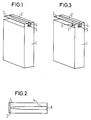
- the structure of a first antenna is shown in Fig. 1.
- the two sheet metal angles 2, 3 acting as antennas are attached to a shielding housing 1 on the upper side.
- the shield housing 1 contains the entire high-frequency, low-frequency and digital electronics of the handset of a cordless telephone.
- the shielding housing 1 also fulfills the function of an earth simulation for the antenna and influences the bandwidth. The larger it is, the smaller the bandwidth.
- the top of the shield housing 1 has been found to be a convenient place for attaching the antenna.
- the shielding housing 1 (or parts thereof) and the sheet metal angles 2, 3 are punched out of a flat sheet metal and bent as shown in FIG. 1.
- a feed line 4 is connected to the first sheet metal bracket 2 and leads out of the interior of the shielding housing 1 via a coaxial feedthrough 5.
- the first sheet metal angle 2 is thus the fed element of the antenna, the second sheet metal angle 3 is radiation-coupled to the first sheet metal angle 2.
- the feed line 4 is connected to a receiver input or transmitter output in the interior of the shielding housing 1 via a duplex filter.
- the 2 shows the attachment point of the feed line 4 on the first sheet metal angle 2.
- the location of this attachment point and the shape of the mutually facing edges of the sheet metal angles 2, 3 allow the input impedance of the antenna to be varied over a wide range.
- the sheet metal angles 2,3 are widened towards the ends. This saves an adaptation network between the antenna and the transmitter output or receiver input.
- the two sheet metal angles 2, 3 have a different length. Due to the resulting different resonance frequencies of the individual radiators, there is a considerable increase in bandwidth compared to a comparable antenna consisting of only a single sheet metal angle.
- FIG. 3 An alternative possibility of connecting the transmitter and receiver to the antenna according to the invention is shown in FIG. 3.
- the first sheet metal bracket 2 is connected to the first feed line 4, the second sheet metal bracket 3 is connected to a second feed line 6.
- the feed lines 4, 6 are led out through bushings 5.
- the transmitter output is via a transmission filter connected to the first sheet metal bracket 2.
- the receiver input is connected to the second sheet metal bracket 3 via a reception filter.
- This type of design results in part of the required decoupling of transmitter output and receiver input.
- the variation of the input impedance by shaping the sheet metal angles 2, 3 and varying the attachment point of the feed lines 4, 6 takes place as in the first exemplary embodiment.
- the shield housing 1 is preceded by two partial antennas on the narrow side.
- the first partial antenna consists of the first two sheet metal angles 2, 3.
- the second partial antenna is constructed identically and consists of sheet metal angles 7,8.
- the feed for the first partial antenna takes place via the feed line 4 through a coaxial feedthrough 5; the same applies accordingly for the second partial antenna.
- the length of the resonators is lambda / 4. Both sub-antennas are of equal length and there is a double resonance.
- a third sheet metal angle 9 is arranged between the two sheet metal angles 2, 3 from the shielding housing 1.
- the free resonator end of the third sheet metal angle 9 is widened symmetrically towards the first two sheet metal angles 2, 3.
- the feed line 4 is connected to the third sheet metal angle 9 via the coaxial feedthrough 5.
- the first two sheet metal angles 2, 3 are radiation-coupled.
- the shield housing 1 consists of two parts and encloses a circuit board 12 on which the components of the device are arranged.
- the circuit board 12 protrudes on the upper narrow side between the parts of the shielding housing 1 and is provided with a ground surface 14.
- the antenna consists of sheet metal angles 10, 11 which have a U-shaped longitudinal section. They are through a solder joint 13 over the entire length of the respective lower leg of the sheet metal angle 10,11 connected to the ground surface 14 and attached to the circuit board 12.
- the feed takes place via a conductor track through the bushing 5 in the shielding housing 1 and a recess in the lower leg of the sheet metal bracket 10 to the feed point 15.
- the sheet metal bracket 10 is also connected to the circuit board 12 here. If necessary, the free resonator end can also be connected to the circuit board 12. Both a separate and a common supply of the sheet metal angles 10, 11 are possible.
- the shielding housing 1 is surrounded by a plastic housing 16.
- the sheet metal angles 2, 3 are sprayed onto the outside of the plastic housing 16. It would also be possible to etch them out.
- the sheet metal bracket 2 is connected to the transmitter / receiver from a feed point 17. The contact between the sheet metal angles 2, 3 and the shielding housing 1 is established via a ground leadthrough 18.
- the antenna of the transmitting and receiving arrangement according to FIG. 8 is made from wire angles 19, 20. They run towards each other and are only a short distance apart at the free resonator end.
- the wire angles 19, 20 are soldered to the shielding housing 1, and the second wire angle 20 is connected to the transmitter / receiver via a feed line 4.
- the shield housing 1 has a coaxial feedthrough 5.
- These wire angles 19, 20 are designed to be straight and therefore have a simple shape.
- the shield housing 1 has no step.
Landscapes
- Engineering & Computer Science (AREA)
- Computer Networks & Wireless Communication (AREA)
- Support Of Aerials (AREA)
- Waveguide Aerials (AREA)
- Transceivers (AREA)
- Mobile Radio Communication Systems (AREA)
- Measuring Pulse, Heart Rate, Blood Pressure Or Blood Flow (AREA)
- Burglar Alarm Systems (AREA)
Abstract
Description
Die Erfindung betrifft eine Sende- und bzw. oder Empfangsanordnung für tragbare Geräte, bestehend aus einem den Hochfrequenzteil enthaltenden Abschirmgehäuse aus Metall und einer Antenne, wobei die Antenne aus zwei oder mehreren miteinander strahlunsgekoppelten und im wesentlichen in Längsrichtung gleichorientierten Antennenresonatoren mit jeweils einem freien Resonatorende und jeweils einem über eine Knickkante abgewinkelten und mit dem Abschirmgehäuse leitend verbundenen Ende besteht.The invention relates to a transmitting and / or receiving arrangement for portable devices, consisting of a shielding housing containing the high-frequency part made of metal and an antenna, the antenna consisting of two or more radiation-coupled and essentially longitudinally oriented antenna resonators, each with a free resonator end and each have an end angled over a kink edge and conductively connected to the shielding housing.
In der EP-A 177 362 ist eine Breitband-Antenne für tragbare Funkgeräte beschrieben. Sie besteht aus zwei abgewinkelten Resonatoren unterschiedlicher Resonanzfrequenz. Beide Resonatoren werden von einer gemeinsamen Leitung aus über eine Abzweigung in der Art einer "Inverted-F-Antenne" gespeist. Die Antennenresonatoren wirken unabhängig voneinander und bilden keine Einheit. Daher ist auch der Wirkungsgrad nicht besonders groß. Der Abstand zwischen den parallelen Schenkeln ist konstant.EP-A 177 362 describes a broadband antenna for portable radio devices. It consists of two angled resonators with different resonance frequencies. Both resonators are fed from a common line via a branch in the manner of an "inverted-F antenna". The antenna resonators work independently of one another and do not form a unit. The efficiency is therefore not particularly high. The distance between the parallel legs is constant.
In der US 4,584,585 ist eine Antenne mit Resonatoren aus Drahtwinkeln beschrieben. Ein Resonator wird am Ende angespeist und bildet eine "Inverted-L-Antenne". Der zweite Resonator ist strahlungsgekoppelt. Mit dieser Anordnung wird zwar ein guter Wirkungsgrad erreicht, die Antenne hat jedoch eine feste Impedanz und ist schlecht anpaßbar. Die Form des aktiven Antennenresonators ist verhältnismäßig schwierig zu biegen, und die Grundplatte weist darüberhinaus auch noch eine Stufe auf. Die Bandbreite ist verhältnismäßig gering.An antenna with resonators made of wire angles is described in US Pat. No. 4,584,585. A resonator is fed in at the end and forms an “inverted L antenna”. The second resonator is radiation-coupled. Although this arrangement achieves good efficiency, the antenna has a fixed impedance and is difficult to adapt. The shape of the active antenna resonator is relatively difficult to bend, and the base plate also has a step. The bandwidth is relatively small.
In der GB-A 2 067 842 ist eine Mikrostreifenantenne beschrieben, die auf eine isolierende Masse aufgebracht ist. Auch hier ist der Abstand zwischen den beiden Antennenresonatoren konstant. Die Resonatoren liegen einander mit den freien Enden gegenüber. Der Speisepunkt liegt nahe dem freien Ende eines Resonators. "Inverted-F-Antennen" sind aus T. Taga und K. Tsunekawa, "Performance Analysis of a Built-In Planar Inverted F Antenna for 800 MHz Band Portable Radio Units," IEEE Trans., Selected Areas in Commun., vol. SAC-5, no.5, pp. 921-929, June (1987) bekannt. Eine Anpassung derartiger Antennen erfolgt durch variation der Position des Speisepunktes.GB-A 2 067 842 describes a microstrip antenna which is applied to an insulating mass. The distance between the two antenna resonators is also constant here. The free ends of the resonators face each other. The feed point is near the free end of a resonator. "Inverted-F antennas" are from T. Taga and K. Tsunekawa, "Performance Analysis of a Built-In Planar Inverted F Antenna for 800 MHz Band Portable Radio Units," IEEE Trans., Selected Areas in Commun., Vol. SAC-5, no.5, pp. 921-929, June (1987). Such antennas are adapted by varying the position of the feed point.
Der Erfindung liegt die Aufgabe zugrunde, die Sende- bzw. Empfangsleistung der Antenne zu verbessern, wobei bei großer Bandbreite eine einfache Herstellbarkeit und gute Anpaßbarkeit gewährleistet sein soll.The invention has for its object to improve the transmission or reception performance of the antenna, wherein easy to manufacture and good adaptability should be ensured with a wide bandwidth.
Dies wird gemäß Patentanspruch 1 durch eine Sende- und/oder Empfangsanordnung für tragbare Geräte erreicht, bestehend aus einem den Hochfrequenzteil enthaltenden Abschirmgehäuse aus Metall und einer Antenne, wobei die Antenne aus zwei oder mehreren miteinander strahlunsgekoppelten und im wesentlichen in Längsrichtung gleichorientierten Antennenresonatoren mit jeweils einem freien Resonatorende und jeweils einem über eine Knickkante abgewinkelten und mit dem Abschirmgehäuse leitend verbundenen Ende besteht, wobei der Senderausgang bzw. Empfängereingang, gegebenenfalls über ein Duplexfilter, durch eine koaxiale Durchführung im Abschirmgehäuse über eine Speiseleitung nur mit dem Speisepunkt eines einzigen Antennenresonators verbunden ist, welcher Speisepunkt zwischen der Knickkante und dem Freien Resonatorende dieses einzigen Antennenresonators liegt, und wobei zum Variieren der Eingangsimpedanz der Antenne die lichte Weite des zwischen zwei benachbarten Antennenresonatoren gebildeten Schlitzes im Bereich des freien Resonatorendes erheblich kleiner ist als an der Knickkante.This is achieved according to
Die nichtgespeisten Resonatoren der Antenne werden strahlungsgekoppelt durch den gespeisten Resonator angeregt, wodurch die Bandbreite der Antenne vergrößert wird. Durch die abgewinkelte Form und die Verbreiterung der Enden fließen Ströme in allen drei Raumrichtungen. Es bilden sich hohe Querströme aus, die eine kleine Impedanz bedingen. Dadurch werden Lücken in der Richtcharakteristik der Antenne gefüllt. Durch den geringen Platzbedarf ist die Anordnung hervorragend für Mobilfunkanwendungen geeignet. Sie ist leicht herstellbar unc die gesamte Hochfrequenz-, Niederfrequenz- und Digitalelektronik eines tragbaren Funkgerätes kann im Abschirmgehäuse untergebracht werden. Das Metallgehäuse dient gleichzeitig als Erdnachbildung für die Antenne. Durch Änderung des Befestigungspunktes der Speiseleitung am Antennenresonator und dadurch, daß zum variieren der Eingangsimpezanz der Antenne die Resonatoren im Bereich ihrer Enden verbreitert sind, ist der Variationsbereich besonders groß. Daher können in vielen Anwendungsfällen Anpassungsnetzwerke zwischen Antenne und Sendeendstufe bzw. Sendefilter, sowie zwischen Antenne und Empfängereingang bzw. Empfangsfilter eingespart werden. Die Anordnung der zueinander im wesentlichen parallelen Antennenresonatoren kann auch als Schlitzantenne beschrieben werden, wobei durch Breite und Form des Schlitzes zwischen den Resonatoren die Eingangsimpedanz in weiten Grenzen variabel ist.The non-powered resonators of the antenna are excited in a radiation-coupled manner by the powered resonator, which increases the bandwidth of the antenna. Due to the angled shape and the widening of the ends, currents flow in all three spatial directions. High cross currents form, the require a small impedance. This fills gaps in the directional characteristics of the antenna. Due to the small space requirement, the arrangement is excellently suitable for mobile radio applications. It is easy to manufacture and the entire high-frequency, low-frequency and digital electronics of a portable radio can be accommodated in the shielding housing. The metal housing also serves as an earth replica for the antenna. The range of variation is particularly large by changing the attachment point of the feed line to the antenna resonator and by virtue of the fact that the resonators are widened in the region of their ends in order to vary the input impedance of the antenna. Therefore, in many applications, adaptation networks between the antenna and the transmission output stage or transmission filter, and between the antenna and the receiver input or reception filter can be saved. The arrangement of the antenna resonators, which are essentially parallel to one another, can also be described as a slot antenna, the width and shape of the slot between the resonators allowing the input impedance to be varied within wide limits.
Die Aufgabe kann nach Patentanspruch 2 auch durch eine Sende- und Empfangsanordnung für tragbare Geräte gelöst werden, bestehend aus einem den Hochfrequenzteil enthaltenden Abschirmgehäuse aus Metall und einer Antenne, wobei die Antenne aus zwei oder mehreren miteinander strahlungsgekoppelten und im wesentlichen in Längsrichtung gleichorientierten Antennenresonatoren mit jeweils einem freien Resonatorende und jeweils einem über eine Knickkante abgewinkelten und mit dem Abschirmgehäuse leitend verbundenen Ende besteht, wobei der Senderausgang und der Empfängereingang jeweils über ein Sendefilter bzw. Empfangsfilter durch eine koaxiale Durchführung im Abschirmgehäuse über je eine Speiseleitung mit dem Speisepunkt eines anderen Antennenresonators verbunden sind, welcher Speisepunkt jeweils zwischen der Knickkante und dem freien Resonatorende des jeweiligen Antennenresonators liegt, und wobei zum variieren der Eingangsimpedanz der Antenne die lichte Weite des zwischen zwei benachbarten Antennenresonatoren gebildeten Schlitzes im Bereich des Freien Resonatorendes erheblich kleiner ist als an der Knickkante.The object can also be achieved according to
Zu den Vorteilen der Anordnung nach Anspruch 1 wird durch die Speisung zweier Antennenresonatoren und die Verbindung der Speiseleitungen mit Sende- und Empfangsfilter eine teilweise Entkoppelung von Senderausgang und Empfängereingang erreicht. Darüberhinaus ist eine getrennte Optimierung von Sender- und Empfängeranpassung möglich.To the advantages of the arrangement according to
Die Antenne kann sich im Prinzip über jeder beliebigen Seitenfläche des Abschirmgehäuses befinden. In Versuchen hat es sich jedoch als günstig erwiesen, daß die Antennenresonatoren an der Oberseite bzw. Deckfläche des Abschirmgehäuses angeordnet sind. Für einen Diversity-Betrieb ist die Antenne aus mindestens zwei gespeisten, einander gegenüberliegenden Teilantennen aufgebaut, die jeweils aus den zwei oder mehreren miteinander strahlungsgekoppelten umd im wesentlichen gleichorientierten Antennenresonatoren bestehen (Fig. 4). Beide Teilantennen können gleich lang sein, es entsteht Doppelresonanz. Die Antenne besteht aus Lambda/4-Resonatoren. Daher kann die Bandbreite noch weiter vergrößert werden, wenn die Länge der Antennenresonatoren ungleich ist.In principle, the antenna can be located above any side surface of the shielding housing. In tests, however, it has proven to be advantageous for the antenna resonators to be arranged on the top or top surface of the shielding housing. For diversity operation, the antenna is constructed from at least two fed, opposing partial antennas, each of which consists of two or more antenna resonators coupled to one another and essentially identically oriented (FIG. 4). Both sub-antennas can be of the same length, creating double resonance. The antenna consists of lambda / 4 resonators. Therefore, the bandwidth can be increased even further if the length of the antenna resonators is unequal.
Ein zuverlässiger mechanischer Aufbau wird dadurch erreicht, daß die abgewinkelten Antennenresonatoren aus Blechwinkeln gebildet sind. Zur Verbesserung der Abstrahlcharakteristik ist es vorteilhaft, daß drei Blechwinkeln vorhanden sind und der mittlere Blechwinkel mit der Speiseleitung verbunden ist. Zur Herstellung der Metallteile in einem einzigen Arbeitsgang ist es vorteilhaft, daß das Abschirmgehäuse und die Blechwinkel aus einem flachen Blech ausgestanzt und in die entsprechende Form gebogen sind. Es ist aber auch möglich, daß die Blechwinkeln auf das Abschirmgehäuse gelötet sind.A reliable mechanical structure is achieved in that the angled antenna resonators are formed from sheet metal angles. To improve the radiation characteristic, it is advantageous that three sheet metal angles are present and the middle sheet metal angle is connected to the feed line. To produce the metal parts in a single operation, it is advantageous that the shielding housing and the sheet metal angles are punched out of a flat sheet metal and bent into the corresponding shape. But it is also possible that the sheet metal brackets are soldered to the shield housing.
Die mechanische Belastbarkeit der Antenne wird dadurch erhöht, daß die Blechwinkel U-förmigen Langsschnitt aufweisen und der nicht gespeiste, bzw. nicht strahlungsgekoppelte Schenkel an einer aus dem Abschirgehäuse herausragenden Platine leitend befestigt und über eine Massefläche mit dem Abschirmgehäuse verbunden ist. Eine besondere Steifigkeit wird dadurch erreicht, daß die Platine zwischen die freien Resonatorenden der Blechwinkel ragt und die Resonatorenenden mit der Platine verbunden sind. Durch diese Maßnahmen ist die Antenne auf der Platine integrierbar.The mechanical strength of the antenna is increased by the fact that the sheet metal angles have a U-shaped longitudinal section and the non-powered or radiation-coupled leg is conductively attached to a board protruding from the shielding housing and is connected to the shielding housing via a ground plane. A particular stiffness is achieved in that the circuit board protrudes between the free resonator ends of the sheet metal angles and the resonator ends are connected to the circuit board. These measures allow the antenna to be integrated on the board.
Eine besondere mechanische Widerstandsfähigkeit ist dadurch gegeben, daß das Abschirmgehäuse von einem Kunststoffgehäuse umgeben ist, auf das die Blechwinkel als Metallfolie außen oder innen aufgebracht und über eine Massedurchführung mit dem Abschirmgehäuse verbunden sind.A special mechanical resistance is given by the fact that the shielding housing is surrounded by a plastic housing, on which the sheet metal angle as a metal foil on the outside or applied inside and connected to the shielding housing via a ground leadthrough.
Darüberhinaus ist es auch vorteilhaft, daß die abgewinkelten Antennenresonatoren aus Drahtwinkeln gebildet sind. Diese Drahtwinkeln laufen derart aufeinander zu, daß ihre freien Resonatorenden nur knapp voneinander entfernt sind. Auch hier fließen dann hohe Ströme und es ergibt sich eine kleine Impedanz. Der "Inverted-F-Aufbau" hat gegenüber dem "Inverted-L-Aufbau" den Vorteil einer höheren Güte der Anpassung an die Breitbandigkeit. Die Verbesserung beträgt etwa 50 - 100 %.In addition, it is also advantageous that the angled antenna resonators are formed from wire angles. These wire angles converge in such a way that their free resonator ends are only a short distance apart. Here, too, high currents flow and there is a low impedance. The "inverted-F structure" has the advantage over the "inverted-L structure" of a higher quality of adaptation to the broadband. The improvement is about 50-100%.
Die Erfindung wird anhand mehrerer Ausführungsbeispiele und von Zeichnungen näher erläutert. Es zeigen:
- Fig. 1 ein Beispiel mit zwei Blechwinkeln,
- Fig. 2 den Grundriß mit dem Antennenbereich,
- Fig. 3 ein Beispiel mit zwei Speiseleitungen,
- Fig. 4 ein Beispiel mit zwei Teilantennen,
- Fig. 5 ein Beispiel mit drei Antennenresonatoren,
- Fig. 6 ein Beispiel der Integration auf einer Platine,
- Fig. 7 ein Beispiel mit Resonatoren aus Metallfolie und
- Fig. 8 ein Beispiel mit Resonatoren aus Drahtwinkeln.
- 1 shows an example with two sheet metal angles,
- 2 shows the plan with the antenna area,
- 3 shows an example with two feed lines,
- 4 shows an example with two partial antennas,
- 5 shows an example with three antenna resonators,
- 6 shows an example of integration on a circuit board,
- Fig. 7 shows an example with resonators made of metal foil and
- 8 shows an example with resonators made of wire angles.
In den folgenden Ausführungsbeispielen werden Antennen mit zwei oder mehreren abgewinkelten Resonatoren beschrieben, die in tragbare Funkgeräte, wie Schnurlos-Telefone, Mobil-Telefone, Pager, "Telepoint-Geräte" etc. einbaubar ist. Als interne Antenne für ein digitales Schnurlos-Telefon ist sie auf das 1,7 GHz-Band eingestellt. Die gemeinsamen Funktionsmerkmale sind im Allgemeinen nur im ersten Ausführungsbeispiel angegeben.In the following exemplary embodiments, antennas with two or more angled resonators are described which can be installed in portable radio devices, such as cordless telephones, mobile telephones, pagers, “telepoint devices” etc. As an internal antenna for a digital cordless telephone, it is set to the 1.7 GHz band. The common functional features are generally only given in the first exemplary embodiment.
Der Aufbau einer ersten Antenne ist in Fig. 1 dargestellt. Auf einem Abschirmgehäuse 1 sind an der Oberseite die beiden als Antenne wirkenden Blechwinkel 2,3 angebracht. Das Abschirmgehäuse 1 beinhaltet die gesamte Hochfrequenz-, Niederfrequenz- und Digitalelektronik des Mobilteiles eines Schnurlos-Telefons.The structure of a first antenna is shown in Fig. 1. The two sheet metal angles 2, 3 acting as antennas are attached to a shielding
Außer der Schirmung erfüllt das Abschirmgehäuse 1 auch die Funktion einer Erdnachbildung für die Antenne und beeinflußt die Bandbreite. Je größer es ist, desto kleiner wird die Bandbreite. Die Oberseite des Abschirmgehäuses 1 hat sich als günstiger Platz für die Anbringung der Antenne herausgestellt.In addition to the shielding, the shielding
Das Abschirmgehäuse 1 (bzw. Teile desselben) und die Blechwinkel 2,3 sind aus einem flachen Blech ausgestanzt und wie in der Fig. 1 dargestellt zurechtgebogen. Mit dem ersten Blechwinkel 2 ist eine Speiseleitung 4 verbunden, die über eine koaxiale Durchführung 5 aus dem Inneren des Abschirmgehäuses 1 herausführt. Der erste Blechwinkel 2 ist somit das gespeiste Element der Antenne, der zweite Blechwinkel 3 ist mit dem ersten Blechwinkel 2 strahlungsgekoppelt. Die Speiseleitung 4 ist im Inneren des Abschirmgehäuses 1 über einen Duplexfilter mit einem Empfängereingang bzw. Senderausgang verbunden.The shielding housing 1 (or parts thereof) and the sheet metal angles 2, 3 are punched out of a flat sheet metal and bent as shown in FIG. 1. A
Fig. 2 zeigt den Befestigungspunkt der Speiseleitung 4 am ersten Blechwinkel 2. Der Ort dieses Befestigungspunktes und die Formgebung der einander zugewandten Kanten der Blechwinkel 2,3 gestattet es, die Eingangsimpedanz der Antenne über einen großen Bereich zu variieren. Die Blechwinkel 2,3 sind zu den Enden hin verbreitert. Dadurch wird ein Anpassungsnetzwerk zwischen der Antenne und dem Senderausgang bzw. Empfängereingang eingespart. Die beiden Blechwinkel 2,3 weisen eine unterschiedliche Länge auf. Aufgrund der daraus folgenden unterschiedlichen Resonanzfrequenzen der Einzelstrahler ergibt sich eine erhebliche Steigerung der Bandbreite gegenüber einer vergleichbaren, nur aus einem einzigen Blechwinkel bestehenden Antenne.2 shows the attachment point of the
Eine alternative Möglichkeit der Verbindung von Sender und Empfänger mit der erfindungsgemäßen Antenne ist in Fig. 3 dargestellt. Der erste Blechwinkel 2 ist mit der ersten Speiseleitung 4 verbunden, der zweite Blechwinkel 3 mit einer zweiten Speiseleitung 6. Die Speiseleitungen 4,6 sind über Durchführungen 5 herausgeführt. Der Senderausgang ist über ein Sendefilter mit dem ersten Blechwinkel 2 verbunden. Entsprechend ist der Empfängereingang über ein Empfangsfilter mit dem zweiten Blechwinkel 3 verbunden. Durch diese Art der Ausführung wird ein Teil der erforderlichen Entkopplung von Senderausgang und Empfängereingang bewirkt. Die Variation der Eingangsimpedanz durch Formgebung der Blechwinkel 2,3 und Variation des Befestigungspunktes der Speiseleitungen 4,6 erfolgt wie beim ersten Ausführungsbeispiel.An alternative possibility of connecting the transmitter and receiver to the antenna according to the invention is shown in FIG. 3. The first
Fig. 4 zeigt eine Antennenanordnung für Diversity-Betrieb. Dem Abschirmgehäuse 1 sind auf der Schmalseite zwei Teilantennen vorgelagert. Die erste Teilantenne besteht aus den ersten beiden Blechwinkeln 2,3. Die zweite Teilantenne ist identisch aufgebaut und besteht aus Blechwinkeln 7,8. Die Anspeisung für die erste Teilantenne erfolgt über die Speiseleitung 4 durch eine koaxiale Durchführung 5, für die zweite Teilantenne gilt entsprechendes. Die Länge der Resonatoren beträgt Lambda/4. Beide Teilantennen sind gleich lang und es kommt zu einer Doppelresonanz.4 shows an antenna arrangement for diversity operation. The
Bei der in Fig. 5 dargestellten Sende- und Empfangsanordnung ist zwischen den beiden Blechwinkeln 2,3 ein dritter Blechwinkel 9 vom Abschirmgehäuse 1 her angeordnet. Das freie Resonatorende des dritten Blechwinkels 9 ist symmetrisch gegen die ersten beiden Blechwinkel 2,3 hin verbreitert. Über die koaxiale Durchführung 5 ist die Speiseleitung 4 mit dem dritten Blechwinkel 9 verbunden. Die beiden ersten Blechwinkel 2,3 sind strahlungsgekoppelt.In the transmission and reception arrangement shown in FIG. 5, a third
Im Beispiel nach Fig. 6 besteht das Abschirmgehäuse 1 aus zwei Teilen und umschließt eine Platine 12, auf der die Bauelemente des Gerätes angeordnet sind. Die Platine 12 ragt auf der oberen Schmalseite zwischen den Teilen des Abschirmgehäuses 1 heraus und ist mit einer Massefläche 14 versehen. Die Antenne besteht aus Blechwinkeln 10,11, die einen U-förmigen Längsschnitt aufweisen. Sie sind durch eine Lötstelle 13 über die ganze Länge des jeweils unteren Schenkels der Blechwinkel 10,11 mit der Massefläche 14 verbunden und an der Platine 12 befestigt. Die Speisung erfolgt über eine Leiterbahn durch die Durchführung 5 im Abschirmgehäuse 1 und eine Ausnehmung im unteren Schenkel des Blechwinkels 10 zum Speisepunkt 15. Auch hier ist der Blechwinkel 10 mit der Platine 12 verbunden. Falls erforderlich, kann auch das freie Resonatorende mit der Platine 12 verbunden werden. Es ist sowohl eine getrennte als auch eine gemeinsame Speisung der Blechwinkel 10,11 möglich.In the example according to FIG. 6, the
Bei einem weiteren Beispiel nach Fig. 7 ist das Abschirmgehäuse 1 von einem Kunststoffgehäuse 16 umgeben. Die Blechwinkel 2,3 sind außen auf das Kunststoffgehäuse 16 aufgespritzt. Es wäre auch möglich, sie herauszuätzen. Von einem Speisepunkt 17 aus ist der Blechwinkel 2 mit dem Sender/Empfänger verbunden. Über eine Massedurchführung 18 wird der Kontakt der Blechwinkel 2,3 mit dem Abschirmgehäuse 1 hergestellt.In a further example according to FIG. 7, the shielding
Die Antenne der Sende- und Empfangsanordnung nach Fig. 8 ist aus Drahtwinkeln 19,20 hergestellt. Sie laufen aufeinander zu und sind am freien Resonatorende nur mehr knapp voneinander entfernt. Die Drahtwinkel 19,20 sind an das Abschirmgehäuse 1 angelötet, und der zweite Drahtwinkel 20 ist über eine Speiseleitung 4 mit dem Sender/Empfänger verbunden. Dazu weist das Abschirmgehäuse 1 eine koaxiale Durchführung 5 auf. Diese Drahtwinkel 19,20 sind gestreckt ausgeführt und haben daher eine einfache Form. Das Abschirmgehäuse 1 weist keine Stufe auf.The antenna of the transmitting and receiving arrangement according to FIG. 8 is made from wire angles 19, 20. They run towards each other and are only a short distance apart at the free resonator end. The wire angles 19, 20 are soldered to the shielding
Claims (13)
- Transmitting and/or receiving arrangement for portable appliances, comprising a shielding housing (1) of metal, containing the radio-frequency section, and an antenna, the antenna comprising two or more antenna resonators (2, 3; 7, 8; 9), which are radiation-coupled to one another and oriented substantially identically in the longitudinal direction, having in each case a free resonator end and in each case an end which is angled-off by means of a bent edge and is conductively connected to the shielding housing (1), the transmitter output and the receiver input being respectively connected, if appropriate via a duplex filter, through a coaxial lead-through (5) in the shielding housing (1) via a feed line (4) only to the feed point of a single antenna resonator (2; 9), which feed point lies between the bent edge and the free resonator end of this single antenna resonator (2; 9), and the clear width of the slit formed between two neighbouring antenna resonators (2, 3; 7, 8; 9) in the region of the free resonator end being considerably smaller than at the bent edge for the purpose of varying the input impedance of the antenna.
- Transmitting and receiving arrangement for portable appliances, comprising a shielding housing (1) of metal, containing the radio-frequency section, and an antenna, the antenna comprising two or more antenna resonators (2, 3; 7, 8; 9), which are radiation-coupled to one another and oriented substantially identically in the longitudinal direction, having in each case a free resonator end and in each case an end which is angled-off by means of a bent edge and is conductively connected to the shielding housing (1), the transmitter output and the receiver input being connected respectively via a transmitting filter and receiving filter through a coaxial lead-through (5) in the shielding housing (1) via a feed line (4, 6) each to the feed point of another antenna resonator (2, 3), which feed point respectively lies between the bent edge and the free resonator end of the respective antenna resonator (2, 3), and the clear width of the slit formed between two neighbouring antenna resonators (2, 3; 7, 8; 9) in the region of the free resonator end being considerably smaller than at the bent edge for the purpose of varying the input impedance of the antenna.
- Arrangement according to Claim 1 or 2, characterized in that the antenna resonators (2, 3; 7, 8; 9) are arranged on the upper side or top surface of the shielding housing (1).
- Arrangement according to Claim 1 or 2, characterized in that the antenna is constructed from at least two fed sub-antennas, lying opposite each other, which in each case comprise the two or more antenna resonators (2, 3, 7, 8) radiation-coupled to one another and oriented substantially identically (Fig. 4).
- Arrangement according to one of the preceding claims, characterized in that the length of the antenna resonators is unequal.
- Arrangement according to one of the preceding claims, characterized in that the angled-off antenna resonators (2, 3; 7, 8; 9) are formed by angled metal sheets.
- Arrangement according to Claim 6, characterized in that there are three angled metal sheets (2, 3, 9) and the middle angled metal sheet (9) is connected to the feed line (4).
- Arrangement according to Claim 6 or 7, characterized in that the shielding housing (1) and the angled metal sheets (2, 3; 7, 8; 9) are punched out from a flat metal sheet and bent into the appropriate shape.
- Arrangement according to Claim 6 or 7, characterized in that the angled metal sheets (2, 3; 7, 8; 9) are soldered on to the shielding housing (1).
- Arrangement according to Claim 6 or 7, characterized in that the angled metal sheets (10, 11) have a U-shaped longitudinal section and the non-fed, or non-radiation-coupled leg is fastened in a conducting manner on a plate (12) protruding out of the shielding housing (1) and is connected via an earthing surface (14) to the shielding housing (1).
- Arrangement according to Claim 10, characterized in that the plate (12) protrudes between the free resonator ends of the angled metal sheets (10, 11) and the resonator ends are connected to the plate (12).
- Arrangement according to Claim 6 or 7, characterized in that the shielding housing (1) is surrounded by a plastic housing (16), to which the angled metal sheets (2, 3) of metal foil are applied on the outside or inside and are connected to the shielding housing (1) via an earthing lead-through (18).
- Arrangement according to one of Claims 1-5, characterized in that the angled-off antenna resonators are formed by angled wires (19, 20).
Applications Claiming Priority (3)
| Application Number | Priority Date | Filing Date | Title |
|---|---|---|---|
| AT1815/89 | 1989-07-27 | ||
| AT1815/89A AT393054B (en) | 1989-07-27 | 1989-07-27 | TRANSMITTER AND / OR RECEIVING ARRANGEMENT FOR PORTABLE DEVICES |
| PCT/EP1990/001227 WO1991002386A1 (en) | 1989-07-27 | 1990-07-26 | Transmitting and receiving arrangement for portable appliances |
Publications (2)
| Publication Number | Publication Date |
|---|---|
| EP0484454A1 EP0484454A1 (en) | 1992-05-13 |
| EP0484454B1 true EP0484454B1 (en) | 1994-09-28 |
Family
ID=3521588
Family Applications (1)
| Application Number | Title | Priority Date | Filing Date |
|---|---|---|---|
| EP90913383A Expired - Lifetime EP0484454B1 (en) | 1989-07-27 | 1990-07-26 | Transmitting and receiving arrangement for portable appliances |
Country Status (6)
| Country | Link |
|---|---|
| US (1) | US5365246A (en) |
| EP (1) | EP0484454B1 (en) |
| JP (1) | JPH05500889A (en) |
| AT (2) | AT393054B (en) |
| DE (1) | DE59007355D1 (en) |
| WO (1) | WO1991002386A1 (en) |
Cited By (4)
| Publication number | Priority date | Publication date | Assignee | Title |
|---|---|---|---|---|
| US6252552B1 (en) | 1999-01-05 | 2001-06-26 | Filtronic Lk Oy | Planar dual-frequency antenna and radio apparatus employing a planar antenna |
| US6366243B1 (en) | 1998-10-30 | 2002-04-02 | Filtronic Lk Oy | Planar antenna with two resonating frequencies |
| EP1249888A2 (en) * | 2001-04-11 | 2002-10-16 | Lg Electronics Inc. | Internal display-mounted antenna for mobile electronic equipment and mobile electronic equipment incorporating same |
| DE19823126B4 (en) * | 1998-05-23 | 2012-08-23 | Ipcom Gmbh & Co. Kg | radio set |
Families Citing this family (95)
| Publication number | Priority date | Publication date | Assignee | Title |
|---|---|---|---|---|
| GR900100864A (en) * | 1990-12-17 | 1992-11-23 | Siemens Ag | Emission and /or reception dispesition for portable appliances |
| JP2705392B2 (en) * | 1991-09-04 | 1998-01-28 | 日本電気株式会社 | Portable radio |
| US5589840A (en) * | 1991-11-05 | 1996-12-31 | Seiko Epson Corporation | Wrist-type wireless instrument and antenna apparatus |
| GB2269499B (en) * | 1992-08-05 | 1996-05-15 | Nokia Mobile Phones Uk | Radio apparatus |
| JP3457351B2 (en) * | 1992-09-30 | 2003-10-14 | 株式会社東芝 | Portable wireless devices |
| FR2699740B1 (en) * | 1992-12-23 | 1995-03-03 | Patrice Brachat | Broadband antenna with reduced overall dimensions, and corresponding transmitting and / or receiving device. |
| US5532705A (en) * | 1993-03-17 | 1996-07-02 | Seiko Epson Corporation | Wrist-mounted-type antenna device and apparatus having the antenna device |
| GB2276274B (en) * | 1993-03-17 | 1997-10-22 | Seiko Epson Corp | Slot antenna device |
| US5757326A (en) * | 1993-03-29 | 1998-05-26 | Seiko Epson Corporation | Slot antenna device and wireless apparatus employing the antenna device |
| GB9309368D0 (en) * | 1993-05-06 | 1993-06-16 | Ncr Int Inc | Antenna apparatus |
| EP0669672B1 (en) * | 1994-02-24 | 1999-12-29 | Ascom AG | Portable radio apparatus |
| RU2137266C1 (en) * | 1994-03-08 | 1999-09-10 | Хагенук Телеком ГмбХ | Pocket-type transmitting and/or receiving device |
| FR2718292B1 (en) * | 1994-04-01 | 1996-06-28 | Christian Sabatier | Antenna for transmitting and / or receiving electromagnetic signals, in particular microwave frequencies, and device using such an antenna. |
| GB2290416B (en) * | 1994-06-11 | 1998-11-18 | Motorola Israel Ltd | An antenna |
| JP3417083B2 (en) * | 1994-10-04 | 2003-06-16 | セイコーエプソン株式会社 | Portable radio |
| US5668560A (en) * | 1995-01-30 | 1997-09-16 | Ncr Corporation | Wireless electronic module |
| EP0736924B1 (en) * | 1995-04-05 | 2002-09-04 | Koninklijke Philips Electronics N.V. | Portable receiver with an antenna |
| US5644319A (en) * | 1995-05-31 | 1997-07-01 | Industrial Technology Research Institute | Multi-resonance horizontal-U shaped antenna |
| CA2197939C (en) * | 1996-02-19 | 2001-05-01 | Kazunari Kawahata | Method of mounting surface mounting antenna on mounting substrate and communication apparatus employing mounting substrate |
| EP0806810A3 (en) * | 1996-05-07 | 1998-04-08 | Ascom Tech Ag | Antenna formed of a strip-like resonance element over a base plate |
| SE507077C2 (en) * | 1996-05-17 | 1998-03-23 | Allgon Ab | Antenna device for a portable radio communication device |
| JP3296189B2 (en) * | 1996-06-03 | 2002-06-24 | 三菱電機株式会社 | Antenna device |
| JP3114621B2 (en) * | 1996-06-19 | 2000-12-04 | 株式会社村田製作所 | Surface mount antenna and communication device using the same |
| EP0818847A3 (en) * | 1996-07-10 | 1998-12-02 | Ascom Tech Ag | Antenna construction |
| DE19740254A1 (en) * | 1996-10-16 | 1998-04-23 | Lindenmeier Heinz | Radio antenna arrangement e.g. for GSM |
| US6002371A (en) * | 1996-11-14 | 1999-12-14 | Brother International Corporation | Die-cut antenna for cordless telephone radio transceiver |
| WO1998042078A2 (en) * | 1997-03-14 | 1998-09-24 | Siemens Aktiengesellschaft | Personal information system and transmission method |
| FI110395B (en) * | 1997-03-25 | 2003-01-15 | Nokia Corp | Broadband antenna is provided with short-circuited microstrips |
| WO1998044588A1 (en) * | 1997-03-31 | 1998-10-08 | Qualcomm Incorporated | Dual-frequency-band patch antenna with alternating active and passive elements |
| US6114996A (en) * | 1997-03-31 | 2000-09-05 | Qualcomm Incorporated | Increased bandwidth patch antenna |
| US6008762A (en) * | 1997-03-31 | 1999-12-28 | Qualcomm Incorporated | Folded quarter-wave patch antenna |
| US5977916A (en) * | 1997-05-09 | 1999-11-02 | Motorola, Inc. | Difference drive diversity antenna structure and method |
| US5926150A (en) * | 1997-08-13 | 1999-07-20 | Tactical Systems Research, Inc. | Compact broadband antenna for field generation applications |
| US6314275B1 (en) * | 1997-08-19 | 2001-11-06 | Telit Mobile Terminals, S.P.A. | Hand-held transmitting and/or receiving apparatus |
| US6064347A (en) * | 1997-12-29 | 2000-05-16 | Scientific-Atlanta, Inc. | Dual frequency, low profile antenna for low earth orbit satellite communications |
| US6429818B1 (en) | 1998-01-16 | 2002-08-06 | Tyco Electronics Logistics Ag | Single or dual band parasitic antenna assembly |
| WO2001033665A1 (en) * | 1999-11-04 | 2001-05-10 | Rangestar Wireless, Inc. | Single or dual band parasitic antenna assembly |
| US6040803A (en) * | 1998-02-19 | 2000-03-21 | Ericsson Inc. | Dual band diversity antenna having parasitic radiating element |
| US6184833B1 (en) * | 1998-02-23 | 2001-02-06 | Qualcomm, Inc. | Dual strip antenna |
| JP3252786B2 (en) * | 1998-02-24 | 2002-02-04 | 株式会社村田製作所 | Antenna device and wireless device using the same |
| US6005524A (en) * | 1998-02-26 | 1999-12-21 | Ericsson Inc. | Flexible diversity antenna |
| US6343208B1 (en) * | 1998-12-16 | 2002-01-29 | Telefonaktiebolaget Lm Ericsson (Publ) | Printed multi-band patch antenna |
| GB2345194B (en) * | 1998-12-22 | 2003-08-06 | Nokia Mobile Phones Ltd | Dual band antenna for a handset |
| US6693603B1 (en) * | 1998-12-29 | 2004-02-17 | Nortel Networks Limited | Communications antenna structure |
| US6381471B1 (en) | 1999-06-30 | 2002-04-30 | Vladimir A. Dvorkin | Dual band radio telephone with dedicated receive and transmit antennas |
| DE69941025D1 (en) * | 1999-07-09 | 2009-08-06 | Ipcom Gmbh & Co Kg | Two band radio |
| JP2001127525A (en) * | 1999-08-18 | 2001-05-11 | Alps Electric Co Ltd | Antenna |
| GB2355114B (en) * | 1999-09-30 | 2004-03-24 | Harada Ind | Dual-band microstrip antenna |
| JP3771094B2 (en) * | 1999-10-04 | 2006-04-26 | アルプス電気株式会社 | Converter for satellite broadcasting reception |
| US6292144B1 (en) * | 1999-10-15 | 2001-09-18 | Northwestern University | Elongate radiator conformal antenna for portable communication devices |
| US6480155B1 (en) * | 1999-12-28 | 2002-11-12 | Nokia Corporation | Antenna assembly, and associated method, having an active antenna element and counter antenna element |
| US6292145B1 (en) | 2000-02-02 | 2001-09-18 | Sun Yu | Angled antenna for portable telephone |
| US6229487B1 (en) * | 2000-02-24 | 2001-05-08 | Ericsson Inc. | Inverted-F antennas having non-linear conductive elements and wireless communicators incorporating the same |
| JP2001257519A (en) * | 2000-03-09 | 2001-09-21 | Alps Electric Co Ltd | Antenna |
| US6326921B1 (en) | 2000-03-14 | 2001-12-04 | Telefonaktiebolaget Lm Ericsson (Publ) | Low profile built-in multi-band antenna |
| US6268831B1 (en) * | 2000-04-04 | 2001-07-31 | Ericsson Inc. | Inverted-f antennas with multiple planar radiating elements and wireless communicators incorporating same |
| FI112724B (en) * | 2000-05-12 | 2003-12-31 | Nokia Corp | Symmetric antenna structure and method of manufacture thereof and the antenna structure applying expansion cards |
| US6853336B2 (en) * | 2000-06-21 | 2005-02-08 | International Business Machines Corporation | Display device, computer terminal, and antenna |
| GB2366453A (en) | 2000-08-31 | 2002-03-06 | Nokia Mobile Phones Ltd | An antenna device for a communication terminal |
| JP3630622B2 (en) * | 2000-08-31 | 2005-03-16 | シャープ株式会社 | Pattern antenna and wireless communication apparatus including the same |
| US7072690B2 (en) * | 2001-04-11 | 2006-07-04 | Lg Electronics Inc. | Multi-band antenna and notebook computer with built-in multi-band antenna |
| US6686886B2 (en) * | 2001-05-29 | 2004-02-03 | International Business Machines Corporation | Integrated antenna for laptop applications |
| JP3660623B2 (en) * | 2001-07-05 | 2005-06-15 | 株式会社東芝 | Antenna device |
| DE10137838A1 (en) * | 2001-08-02 | 2003-02-13 | Philips Corp Intellectual Pty | GPS receiver module |
| EP1294050A1 (en) * | 2001-09-05 | 2003-03-19 | Z-Com, Inc. | Inverted-F antenna |
| DE10204079A1 (en) * | 2002-02-01 | 2003-08-21 | Imst Gmbh | Mobile radiotelephone antenna, has coupling region with average diameter that is less than half quarter-wavelength of lowest resonant frequency of antenna |
| GB0208130D0 (en) * | 2002-04-09 | 2002-05-22 | Koninkl Philips Electronics Nv | Improvements in or relating to wireless terminals |
| GB0210601D0 (en) * | 2002-05-09 | 2002-06-19 | Koninkl Philips Electronics Nv | Antenna arrangement and module including the arrangement |
| EP2230723A1 (en) * | 2002-09-10 | 2010-09-22 | Fractus, S.A. | Coupled multiband antennas |
| BR0215864A (en) * | 2002-09-10 | 2005-07-05 | Fractus Sa | Antenna device and handheld antenna |
| US6917339B2 (en) * | 2002-09-25 | 2005-07-12 | Georgia Tech Research Corporation | Multi-band broadband planar antennas |
| JP3916068B2 (en) * | 2002-11-06 | 2007-05-16 | ソニー・エリクソン・モバイルコミュニケーションズ株式会社 | Wireless device |
| US6850196B2 (en) * | 2003-01-06 | 2005-02-01 | Vtech Telecommunications, Limited | Integrated inverted F antenna and shield can |
| TW574767B (en) * | 2003-01-13 | 2004-02-01 | Uniwill Comp Corp | Antenna and shield assembly and wireless transmission module thereof |
| EP1597794B1 (en) * | 2003-02-19 | 2008-08-20 | Fractus S.A. | Miniature antenna having a volumetric structure |
| CN100414771C (en) * | 2003-06-30 | 2008-08-27 | 日本电气株式会社 | Antenna structure and communication apparatus |
| EP1507314A1 (en) * | 2003-08-12 | 2005-02-16 | High Tech Computer Corp. | Perpendicularly-oriented inverted F antenna |
| CN100438213C (en) * | 2003-08-13 | 2008-11-26 | 宏达国际电子股份有限公司 | Vertical reverse F-shape antenna |
| DE102005031329A1 (en) * | 2005-02-19 | 2006-08-24 | Hirschmann Electronics Gmbh | Dual-band ultra-flat antenna for satellite communication |
| JP4311576B2 (en) * | 2005-11-18 | 2009-08-12 | ソニー・エリクソン・モバイルコミュニケーションズ株式会社 | Folded dipole antenna device and portable radio terminal |
| US8044860B2 (en) * | 2005-11-23 | 2011-10-25 | Industrial Technology Research Institute | Internal antenna for mobile device |
| JP4951964B2 (en) * | 2005-12-28 | 2012-06-13 | 富士通株式会社 | Antenna and wireless communication device |
| US9064198B2 (en) | 2006-04-26 | 2015-06-23 | Murata Manufacturing Co., Ltd. | Electromagnetic-coupling-module-attached article |
| JP4674638B2 (en) * | 2006-04-26 | 2011-04-20 | 株式会社村田製作所 | Article with electromagnetic coupling module |
| GB2439601A (en) * | 2006-06-30 | 2008-01-02 | Nokia Corp | A moulded housing member with an integrated antenna element for a portable device |
| TWI368354B (en) * | 2008-07-01 | 2012-07-11 | Avermedia Tech Inc | Inside digital tv antenna |
| US9653813B2 (en) | 2011-05-13 | 2017-05-16 | Google Technology Holdings LLC | Diagonally-driven antenna system and method |
| JP5301608B2 (en) * | 2011-05-24 | 2013-09-25 | レノボ・シンガポール・プライベート・リミテッド | Antenna for wireless terminal equipment |
| GB2509297A (en) | 2012-10-11 | 2014-07-02 | Microsoft Corp | Multiband antenna |
| JP2014110555A (en) * | 2012-12-03 | 2014-06-12 | Samsung Electronics Co Ltd | Antenna device |
| TWI617085B (en) * | 2013-05-31 | 2018-03-01 | 群邁通訊股份有限公司 | Antenna structure and wireless communication device using same |
| CN104241843B (en) * | 2013-06-06 | 2018-07-27 | 深圳富泰宏精密工业有限公司 | The wireless communication device of antenna structure and the application antenna structure |
| EP2884580B1 (en) | 2013-12-12 | 2019-10-09 | Electrolux Appliances Aktiebolag | Antenna arrangement and kitchen apparatus |
| CN107395788B (en) * | 2016-05-17 | 2021-03-23 | 北京小米移动软件有限公司 | Terminal shell and terminal |
| EP3474376B1 (en) * | 2017-10-17 | 2022-07-27 | Advanced Automotive Antennas, S.L.U. | Broadband antenna system |
Citations (2)
| Publication number | Priority date | Publication date | Assignee | Title |
|---|---|---|---|---|
| EP0177362A2 (en) * | 1984-10-04 | 1986-04-09 | Nec Corporation | Portable radio communication apparatus comprising an antenna member for a broad-band signal |
| US4584585A (en) * | 1984-04-04 | 1986-04-22 | Motorola, Inc. | Two element low profile antenna |
Family Cites Families (9)
| Publication number | Priority date | Publication date | Assignee | Title |
|---|---|---|---|---|
| GB2067842B (en) * | 1980-01-16 | 1983-08-24 | Secr Defence | Microstrip antenna |
| DE3465840D1 (en) * | 1983-03-19 | 1987-10-08 | Nec Corp | Double loop antenna |
| US4516127A (en) * | 1983-04-29 | 1985-05-07 | Motorola, Inc. | Three element low profile antenna |
| US4494120A (en) * | 1983-04-29 | 1985-01-15 | Motorola, Inc. | Two element low profile antenna |
| AT387117B (en) * | 1986-07-10 | 1988-12-12 | Siemens Ag Oesterreich | Transmitting and/or receiving arrangement for portable devices |
| US4800392A (en) * | 1987-01-08 | 1989-01-24 | Motorola, Inc. | Integral laminar antenna and radio housing |
| US4876552A (en) * | 1988-04-27 | 1989-10-24 | Motorola, Inc. | Internally mounted broadband antenna |
| US4849765A (en) * | 1988-05-02 | 1989-07-18 | Motorola, Inc. | Low-profile, printed circuit board antenna |
| US5144324A (en) * | 1989-08-02 | 1992-09-01 | At&T Bell Laboratories | Antenna arrangement for a portable transceiver |
-
1989
- 1989-07-27 AT AT1815/89A patent/AT393054B/en not_active IP Right Cessation
-
1990
- 1990-07-26 US US07/828,792 patent/US5365246A/en not_active Expired - Fee Related
- 1990-07-26 DE DE59007355T patent/DE59007355D1/en not_active Expired - Fee Related
- 1990-07-26 WO PCT/EP1990/001227 patent/WO1991002386A1/en active IP Right Grant
- 1990-07-26 AT AT90913383T patent/ATE112421T1/en not_active IP Right Cessation
- 1990-07-26 EP EP90913383A patent/EP0484454B1/en not_active Expired - Lifetime
- 1990-07-26 JP JP2512360A patent/JPH05500889A/en active Pending
Patent Citations (2)
| Publication number | Priority date | Publication date | Assignee | Title |
|---|---|---|---|---|
| US4584585A (en) * | 1984-04-04 | 1986-04-22 | Motorola, Inc. | Two element low profile antenna |
| EP0177362A2 (en) * | 1984-10-04 | 1986-04-09 | Nec Corporation | Portable radio communication apparatus comprising an antenna member for a broad-band signal |
Cited By (5)
| Publication number | Priority date | Publication date | Assignee | Title |
|---|---|---|---|---|
| DE19823126B4 (en) * | 1998-05-23 | 2012-08-23 | Ipcom Gmbh & Co. Kg | radio set |
| US6366243B1 (en) | 1998-10-30 | 2002-04-02 | Filtronic Lk Oy | Planar antenna with two resonating frequencies |
| US6252552B1 (en) | 1999-01-05 | 2001-06-26 | Filtronic Lk Oy | Planar dual-frequency antenna and radio apparatus employing a planar antenna |
| EP1249888A2 (en) * | 2001-04-11 | 2002-10-16 | Lg Electronics Inc. | Internal display-mounted antenna for mobile electronic equipment and mobile electronic equipment incorporating same |
| EP1764860A1 (en) * | 2001-04-11 | 2007-03-21 | LG Electronics Inc. | Internal display-mounted antenna for mobile electronic equipment and mobile electronic equipment incorporating same |
Also Published As
| Publication number | Publication date |
|---|---|
| DE59007355D1 (en) | 1994-11-03 |
| AT393054B (en) | 1991-08-12 |
| US5365246A (en) | 1994-11-15 |
| ATE112421T1 (en) | 1994-10-15 |
| EP0484454A1 (en) | 1992-05-13 |
| ATA181589A (en) | 1990-12-15 |
| JPH05500889A (en) | 1993-02-18 |
| WO1991002386A1 (en) | 1991-02-21 |
Similar Documents
| Publication | Publication Date | Title |
|---|---|---|
| EP0484454B1 (en) | Transmitting and receiving arrangement for portable appliances | |
| DE60109608T2 (en) | ANTENNA AND RADIO UNIT WITH ANY SUCH ANTENNA | |
| DE60026276T2 (en) | Antenna structure, method for coupling a signal to the antenna structure, antenna unit and mobile station with such an antenna structure | |
| EP3635814B1 (en) | Dual-polarised crossed dipole and antenna arrangement having two such dual-polarised crossed dipoles | |
| DE60302487T2 (en) | Multi-resonance antenna, antenna module and radio with such a multiple-resonance antenna | |
| DE60211889T2 (en) | BROADBAND ANTENNA FOR WIRELESS COMMUNICATION | |
| DE69829431T2 (en) | Antenna with circular polarization | |
| DE69816583T2 (en) | Antenna for mobile communication device | |
| EP0952625B1 (en) | Antenna for several radio communications services | |
| DE60018011T2 (en) | Flachantenne | |
| DE69835246T2 (en) | Double resonant antenna structure for several frequency ranges | |
| DE60213543T2 (en) | Increasing the electrical isolation between two antennas of a radio | |
| DE69924104T2 (en) | Asymmetric dipole antenna arrangement | |
| DE69813357T2 (en) | Antenna for telecommunication devices | |
| DE102007056258B4 (en) | Chip antenna and associated printed circuit board for a mobile telecommunication device | |
| DE60104756T2 (en) | Surface mounted antenna, method of adjusting and adjusting the two-frequency resonance of the antenna and communication device with such an antenna | |
| DE102008007258A1 (en) | Multi-band antenna and mobile communication terminal, which has these | |
| DE19912465C2 (en) | Multi-area antenna system | |
| DE10226910A1 (en) | Surface mount type antenna and radio transmitter and receiver using the same | |
| EP0795926A2 (en) | Flat, three-dimensional antenna | |
| WO2001003238A1 (en) | Integrable dual-band antenna | |
| WO2000052784A1 (en) | Integrable multiband antenna | |
| EP1323207A1 (en) | Mobile telephone comprising a multi-band antenna | |
| DE60212429T2 (en) | DIELECTRIC ANTENNA | |
| DE19822371B4 (en) | Antenna arrangement and radio |
Legal Events
| Date | Code | Title | Description |
|---|---|---|---|
| PUAI | Public reference made under article 153(3) epc to a published international application that has entered the european phase |
Free format text: ORIGINAL CODE: 0009012 |
|
| 17P | Request for examination filed |
Effective date: 19911108 |
|
| AK | Designated contracting states |
Kind code of ref document: A1 Designated state(s): AT BE CH DE DK ES FR GB IT LI LU NL SE |
|
| 17Q | First examination report despatched |
Effective date: 19931220 |
|
| GRAA | (expected) grant |
Free format text: ORIGINAL CODE: 0009210 |
|
| AK | Designated contracting states |
Kind code of ref document: B1 Designated state(s): AT BE CH DE DK ES FR GB IT LI LU NL SE |
|
| PG25 | Lapsed in a contracting state [announced via postgrant information from national office to epo] |
Ref country code: IT Free format text: LAPSE BECAUSE OF FAILURE TO SUBMIT A TRANSLATION OF THE DESCRIPTION OR TO PAY THE FEE WITHIN THE PRE;WARNING: LAPSES OF ITALIAN PATENTS WITH EFFECTIVE DATE BEFORE 2007 MAY HAVE OCCURRED AT ANY TIME BEFORE 2007. THE CORRECT EFFECTIVE DATE MAY BE DIFFERENT FROM THE ONE RECORDED.SCRIBED TIME-LIMIT Effective date: 19940928 Ref country code: DK Effective date: 19940928 Ref country code: GB Effective date: 19940928 Ref country code: ES Free format text: THE PATENT HAS BEEN ANNULLED BY A DECISION OF A NATIONAL AUTHORITY Effective date: 19940928 Ref country code: FR Effective date: 19940928 Ref country code: BE Effective date: 19940928 Ref country code: NL Effective date: 19940928 |
|
| RAP1 | Party data changed (applicant data changed or rights of an application transferred) |
Owner name: SIEMENS AKTIENGESELLSCHAFT Owner name: SIEMENS AKTIENGESELLSCHAFT OESTERREICH |
|
| REF | Corresponds to: |
Ref document number: 112421 Country of ref document: AT Date of ref document: 19941015 Kind code of ref document: T |
|
| REF | Corresponds to: |
Ref document number: 59007355 Country of ref document: DE Date of ref document: 19941103 |
|
| PG25 | Lapsed in a contracting state [announced via postgrant information from national office to epo] |
Ref country code: SE Effective date: 19941228 |
|
| EN | Fr: translation not filed | ||
| NLV1 | Nl: lapsed or annulled due to failure to fulfill the requirements of art. 29p and 29m of the patents act | ||
| GBV | Gb: ep patent (uk) treated as always having been void in accordance with gb section 77(7)/1977 [no translation filed] |
Effective date: 19940928 |
|
| PG25 | Lapsed in a contracting state [announced via postgrant information from national office to epo] |
Ref country code: AT Effective date: 19950726 |
|
| PLBE | No opposition filed within time limit |
Free format text: ORIGINAL CODE: 0009261 |
|
| STAA | Information on the status of an ep patent application or granted ep patent |
Free format text: STATUS: NO OPPOSITION FILED WITHIN TIME LIMIT |
|
| PG25 | Lapsed in a contracting state [announced via postgrant information from national office to epo] |
Ref country code: CH Effective date: 19950731 Ref country code: LI Effective date: 19950731 Ref country code: LU Free format text: LAPSE BECAUSE OF NON-PAYMENT OF DUE FEES Effective date: 19950731 |
|
| 26N | No opposition filed | ||
| REG | Reference to a national code |
Ref country code: CH Ref legal event code: PL |
|
| PGFP | Annual fee paid to national office [announced via postgrant information from national office to epo] |
Ref country code: DE Payment date: 19970918 Year of fee payment: 8 |
|
| PG25 | Lapsed in a contracting state [announced via postgrant information from national office to epo] |
Ref country code: DE Free format text: LAPSE BECAUSE OF NON-PAYMENT OF DUE FEES Effective date: 19990501 |