DE10238564B4 - pipetting - Google Patents
pipetting Download PDFInfo
- Publication number
- DE10238564B4 DE10238564B4 DE10238564A DE10238564A DE10238564B4 DE 10238564 B4 DE10238564 B4 DE 10238564B4 DE 10238564 A DE10238564 A DE 10238564A DE 10238564 A DE10238564 A DE 10238564A DE 10238564 B4 DE10238564 B4 DE 10238564B4
- Authority
- DE
- Germany
- Prior art keywords
- opening
- pipetting device
- micropump
- pump chamber
- valve
- Prior art date
- Legal status (The legal status is an assumption and is not a legal conclusion. Google has not performed a legal analysis and makes no representation as to the accuracy of the status listed.)
- Expired - Lifetime
Links
Classifications
-
- F—MECHANICAL ENGINEERING; LIGHTING; HEATING; WEAPONS; BLASTING
- F04—POSITIVE - DISPLACEMENT MACHINES FOR LIQUIDS; PUMPS FOR LIQUIDS OR ELASTIC FLUIDS
- F04B—POSITIVE-DISPLACEMENT MACHINES FOR LIQUIDS; PUMPS
- F04B43/00—Machines, pumps, or pumping installations having flexible working members
- F04B43/02—Machines, pumps, or pumping installations having flexible working members having plate-like flexible members, e.g. diaphragms
- F04B43/04—Pumps having electric drive
- F04B43/043—Micropumps
- F04B43/046—Micropumps with piezoelectric drive
-
- B—PERFORMING OPERATIONS; TRANSPORTING
- B01—PHYSICAL OR CHEMICAL PROCESSES OR APPARATUS IN GENERAL
- B01L—CHEMICAL OR PHYSICAL LABORATORY APPARATUS FOR GENERAL USE
- B01L3/00—Containers or dishes for laboratory use, e.g. laboratory glassware; Droppers
- B01L3/02—Burettes; Pipettes
-
- B—PERFORMING OPERATIONS; TRANSPORTING
- B01—PHYSICAL OR CHEMICAL PROCESSES OR APPARATUS IN GENERAL
- B01L—CHEMICAL OR PHYSICAL LABORATORY APPARATUS FOR GENERAL USE
- B01L2300/00—Additional constructional details
- B01L2300/06—Auxiliary integrated devices, integrated components
- B01L2300/0681—Filter
-
- B—PERFORMING OPERATIONS; TRANSPORTING
- B01—PHYSICAL OR CHEMICAL PROCESSES OR APPARATUS IN GENERAL
- B01L—CHEMICAL OR PHYSICAL LABORATORY APPARATUS FOR GENERAL USE
- B01L2400/00—Moving or stopping fluids
- B01L2400/04—Moving fluids with specific forces or mechanical means
- B01L2400/0403—Moving fluids with specific forces or mechanical means specific forces
- B01L2400/0433—Moving fluids with specific forces or mechanical means specific forces vibrational forces
- B01L2400/0439—Moving fluids with specific forces or mechanical means specific forces vibrational forces ultrasonic vibrations, vibrating piezo elements
-
- B—PERFORMING OPERATIONS; TRANSPORTING
- B01—PHYSICAL OR CHEMICAL PROCESSES OR APPARATUS IN GENERAL
- B01L—CHEMICAL OR PHYSICAL LABORATORY APPARATUS FOR GENERAL USE
- B01L2400/00—Moving or stopping fluids
- B01L2400/06—Valves, specific forms thereof
- B01L2400/0622—Valves, specific forms thereof distribution valves, valves having multiple inlets and/or outlets, e.g. metering valves, multi-way valves
-
- B—PERFORMING OPERATIONS; TRANSPORTING
- B01—PHYSICAL OR CHEMICAL PROCESSES OR APPARATUS IN GENERAL
- B01L—CHEMICAL OR PHYSICAL LABORATORY APPARATUS FOR GENERAL USE
- B01L2400/00—Moving or stopping fluids
- B01L2400/06—Valves, specific forms thereof
- B01L2400/0633—Valves, specific forms thereof with moving parts
- B01L2400/0638—Valves, specific forms thereof with moving parts membrane valves, flap valves
Landscapes
- Engineering & Computer Science (AREA)
- Mechanical Engineering (AREA)
- General Engineering & Computer Science (AREA)
- Health & Medical Sciences (AREA)
- Clinical Laboratory Science (AREA)
- Chemical & Material Sciences (AREA)
- Chemical Kinetics & Catalysis (AREA)
- Reciprocating Pumps (AREA)
Abstract
Pipettiereinrichtung
mit folgenden Merkmalen:
einer Mikropumpe (200) mit
einer
Pumpenkammer (216) mit einer ersten Öffnung (222) und einer zweiten Öffnung (224);
einer
Einrichtung (246, 250) zum Verändern
des Volumens der Pumpenkammer (216), wobei die Einrichtung (246, 250)
eine Membran und eine Betätigungseinrichtung
zum Betätigen
der Membran umfasst;
einem ersten aktiven Ventil (226) zum Öffnen und
Schließen
der ersten Öffnung
(222);
einem zweiten aktiven Ventil (236) zum Öffnen und
Schließen
der zweiten Öffnung
(224);
einer Pipettenspitze (258), die über den Pipettenkanal (256)
mit der ersten (222) Öffnung
verbunden ist; und
einer Steuereinrichtung, die ausgebildet
ist,
um das erste aktive Ventil (226) zum Schließen der
ersten Öffnung
(222) zu betätigen,
um
das zweite aktive Ventil (236) zum Öffnen der zweiten Öffnung (224)
zu betätigen,
wodurch die Pumpenkammer (216) mit dem Pipettenkanal (256) verbunden
wird,
um die Betätigungseinrichtung
zum Vergrößern eines
Volumens der...Pipetting device with the following features:
a micropump (200) with
a pumping chamber (216) having a first opening (222) and a second opening (224);
means (246, 250) for varying the volume of the pumping chamber (216), the means (246, 250) comprising a diaphragm and actuator means for actuating the diaphragm;
a first active valve (226) for opening and closing the first opening (222);
a second active valve (236) for opening and closing the second opening (224);
a pipette tip (258) connected to the first (222) port via the pipette channel (256); and
a control device which is designed
to actuate the first active valve (226) to close the first opening (222),
to actuate the second active valve (236) to open the second orifice (224), thereby connecting the pumping chamber (216) to the pipette channel (256),
around the actuator to increase a volume of the ...
Description
Die vorliegende Erfindung bezieht sich auf Pipettiereinrichtungen und spezifischer auf Pipettiereinrichtungen mit Mikropumpen.The The present invention relates to pipetting devices and more specifically to pipetting devices with micropumps.
Mit zunehmender Verbesserung der Herstellung von mikromechanischen Strukturen können heutzutage vielfältige Vorrichtungen als Mikrostrukturvorrichtungen realisiert werden. Eine solche Mikrostrukturvorrichtung umfaßt beispielsweise eine Mikropipettiereinrichtung mit einer Mikropumpe.With increasing improvement in the production of micromechanical structures can nowadays diverse Devices are realized as microstructure devices. Such a microstructure device comprises, for example, a micropipetting device with a micropump.
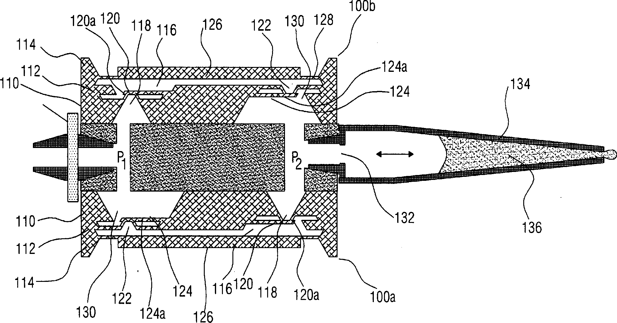
Die
Pumpenkammer
Ferner
weisen die Mikropumpen
Bei
einem Saugvorgang wird an das piezoelektrische Betätigungselement
Bei
einem Pumpvorgang wird das Pumpkammervolumen durch ein Anlegen einer
elektrischen Spannung an das piezoelektrische Betätigungselement
In
der Pipettiereinrichtung ist die Mikropumpe
Beim
Ansaugen eines zu dosierenden Mediums wird die saugseitig an den
Pipettenkanal angeschlossene Mikropumpe
Umgekehrt
wird bei einem Dosieren des angesaugten Mediums die Mikropumpe
Die
oben beschriebenen Mikropumpen
Die
Verwendung von passiven Rückschlagventilen
bei den Mikropumpen
Bei
dem Einsatz der Mikropumpen
Ein
wesentlicher Nachteil der Mikropumpen
Bekannterweise
kann die Gefahr des fluidischen Kurzschlusses durch ein geeignetes
Ansteuern des piezoelektrischen Elements
Ein
weiterer Nachteil der oben beschriebenen bekannten Pipettiereinrichtung
besteht darin, daß die
Herstellung derselben aufwendig ist. Die Mikropumpen
Ferner
muß bei
den bekannten Mikropumpen
Alternativ kann bei der Herstellung des mittleren Pumpenkörperabschnitts auch ein dünner Wafer als Ausgangswafer verwendet werden. Um die dünnen Wafer während des Herstellungsprozesses geeignet zu transportieren und zu lagern, sind jedoch aufwendige und speziell an die dünnen Wafer angepaßte Handhabungsvorrichtungen erforderlich. Ferner besteht bei dem Umgang mit den dünnen Wafern die Gefahr eines Bruchs des Wafers, wodurch bei einer Massenfertigung die Ausschußrate erhöht wird und die Herstellungskosten steigen.alternative For example, in the manufacture of the central pump body section, a thin wafer may also be used be used as the starting wafer. To the thin wafers during the Manufacturing process suitable to transport and store, However, are complex and specially adapted to the thin wafer handling devices required. Furthermore, when dealing with the thin wafers, the Risk of breakage of the wafer, resulting in mass production the reject rate elevated will increase and the cost of production.
Ein
weiterer Nachteil, der sich bei den Mikropumpen
Ferner
muß zum
Bilden des Auslaß-Klappenventils
Darüber hinaus
besteht ein wesentlicher Nachteil der Pipettiereinrichtung gemäß
Eine
Pipettiereinrichtung, die entsprechend zu der unter Bezugnahme auf
Eine
Pipettiereinrichtung, die entsprechend zu der unter Bezugnahme auf
Die WO 99/10 099 A1 offenbart ein Mikrodosiersystem, das eine Mikromembranpumpe und einen Freistrahldosierer umfaßt. Die Mikromembranpumpe ist mittels eines Eingangs mit einem Reservoir verbunden und weist ferner einen Ausgang auf, der mittels einer Leitung mit einem Eingang des Freistrahldosierers verbunden ist. Am Eingang und Ausgang der Mikromembranpumpe sind passive Rückschlagventile vorgesehen, so dass eine Flüssigkeit von dem Reservoir zu dem Freistrahldosierer gepumpt werden kann. Der Freistrahldosierer umfaßt ferner eine Druckkammer mit zwei Öffnungen, die jeweils einen Eingang bzw. Ausgang des Freistrahldosierers bilden. Die Mikromembranpumpe und der Freistrahldosierer umfassen ferner jeweils eine Membran, um ein Volumen der Druckkammer zu verändern.The WO 99/10 099 A1 discloses a microdosing system comprising a micromembrane pump and a free jet dispenser. The micromembrane pump is connected by means of an input to a reservoir and further has an output connected by a line to an input of the Free jet is connected. At the entrance and exit of the micromembrane pump are passive check valves provided so that a liquid of the reservoir can be pumped to the free jet dispenser. Of the Free jet dispenser further includes a pressure chamber with two openings, each forming an input or output of the free jet dispenser. The micromembrane pump and the free jet dispenser further include one membrane each to change a volume of the pressure chamber.
Die
Das Ventil ist mittels eines piezoelektrischen Antriebs betreibbar, der eine bewegbare Membran zum Verschließen betätigt.The Valve is operable by means of a piezoelectric drive, which actuates a movable membrane for closing.
Die
Die
Die Aufgabe der vorliegenden Erfindung besteht darin, eine Pipettiereinrichtung zu schaffen, die ein sicheres und stabiles Dosieren eines Dosierfluids ermöglicht.The The object of the present invention is a pipetting device to provide a safe and stable dosing of a dosing.
Diese Aufgabe wird durch eine Pipettiereinrichtung gemäß Anspruch 1 gelöst.These The object is achieved by a pipetting device according to claim 1.
Die vorliegende Erfindung schafft eine Pipettiereinrichtung mit den Merkmalen des Patentanspruchs 1.The The present invention provides a pipetting device with the Features of claim 1.
Die vorliegende Erfindung basiert auf der Erkenntnis, daß eine Pipettiereinrichtung mit einer Mikropumpe mit einem stabilen und sicheren Dosierverhalten realisiert werden kann, indem von der Verwendung einer Mikropumpe mit passiven Ventilen zum Öffnen bzw. Schließen von Öffnungen einer Pumpenkammer Abstand genommen wird. Bei der erfindungsgemäßen Pipettiereinrichtung wird eine Mikropumpe mit aktiven Ventilen zum Öffnen und Verschließen der Pumpenkammeröffnungen verwendet.The The present invention is based on the finding that a pipetting device with a micropump with a stable and safe dosing behavior can be realized by the use of a micropump with passive valves for opening or Close of openings a pump chamber is removed. In the pipetting device according to the invention is a micropump with active valves to open and close the Pump chamber openings uses.
Dadurch sind die Öffnungen der Pumpenkammer selbst bei auftretenden Gegendrücken sicher verschließbar. Dies verhindert einen fluidischen Kurzschluß bei hohen Druckpulsen und vermeidet das Auftreten von Leckraten.Thereby are the openings the pump chamber can be closed safely even when back pressures occur. This prevents a fluidic short circuit at high pressure pulses and avoids the occurrence of leak rates.
Die Verwendung einer Mikropumpe mit aktiven Ventilen ermöglicht ein Betreiben in zwei Pumprichtungen, so daß zum Ansaugen und Dosieren lediglich eine Mikropumpe erforderlich ist.The use of a micropump with akti The valves enable operation in two pumping directions, so that only one micropump is required for aspiration and metering.
Durch die aktiven Ventile wird ferner eine einfache Fluidführung erreicht, da der Verlauf des ein- oder ausströmenden Fluids im Gegensatz zu den bekannten Mikropumpen mit Klappenventilen nicht durch die Klappen behindert wird. Dadurch ergibt sich in Ein- und Auslaßkanälen, die mit den Öffnungen verbunden sind, ebenfalls eine einfache Fluidführung. Ferner können die Öffnungen mit einer einfachen und symmetrischen Form gebildet werden. Dies vereinfacht ein Strukturieren der Öffnungen bei der Herstellung der Mikropumpe.By the active valves are also achieved a simple fluid management, because the course of the incoming or outflowing fluid in contrast to the known micropumps with flap valves not through the Flaps is obstructed. This results in inlet and outlet ports, the with the openings are connected, also a simple fluid guide. Furthermore, the openings be formed with a simple and symmetrical shape. This simplifies structuring of the openings during manufacture the micropump.
Darüberhinaus ist bei der Pipettiereinrichtung ein Herstellungsprozess einfach gehalten, da daß kritische Erzeugen von dünnen flexiblen Klappen nicht erforderlich ist.Furthermore In the pipetting device, a manufacturing process is simple kept that critical Generating thin flexible flaps is not required.
Im Gegensatz zu der bekannten Pipettiereinrichtung mit einer Mikropumpe mit passiven Klappenventilen ist es bei der erfindungsgemäßen Pipettiereinrichtung mit einer Mikropumpe mit aktiven Ventilen nicht erforderlich, eine längliche Ventilklappe in einem großdimensionierten Auslaßkanal eines Pumpenkörpers anzuordnen. Dadurch kann eine äußere Oberfläche des Pumpenkörpers eine große Befestigungsfläche zum Befestigen der Mikropumpe an einem Träger aufweisen, so daß eine einfache und sichere Befestigung der Mikropumpe möglich ist.in the Contrary to the known pipetting device with a micropump with passive flap valves, it is in the pipetting device according to the invention with a micropump with active valves not required, one elongated Valve flap in a large-sized outlet channel a pump body to arrange. This allows an outer surface of the pump body a big mounting surface for attaching the micropump to a carrier, so that a simple and secure attachment of the micropump is possible.
Ein bevorzugtes Ausführungsbeispiel der Pipettiereinrichtung umfaßt eine Mikropumpe, bei der die aktiven Ventile als piezoelektrische Ventile vorliegen. Ferner weist die Einrichtung zum Verändern des Volumens der Pumpenkammer vorzugsweise eine Pumpenmembran auf, die mit einer piezoelektrischen Betätigungseinrichtung zum Verändern des Volumens betätigbar ist. Die piezoelektrische Betätigungseinrichtung umfaßt vorzugsweise eine dünne piezo-aktive Schicht, die auf einer äußeren Seite der Pumpenmembran aufgebracht ist.One preferred embodiment the pipetting device comprises a micropump, in which the active valves as piezoelectric Valves are present. Further, the means for changing the volume the pump chamber preferably a pump diaphragm, which with a piezoelectric actuator to change of the volume actuated is. The piezoelectric actuator comprises preferably a thin piezoactive Layer on an outer side the pump diaphragm is applied.
Die Pumpenmembran ist vorzugsweise zwischen Halteelementen angeordnet, die ein Verbiegen der Membran ermöglichen, ohne daß nachteilige Auswirkungen auf die aktiven Ventile in Kauf genommen werden müssen.The Pump diaphragm is preferably arranged between holding elements, which allow bending of the membrane without adverse effects must be accepted on the active valves.
Die Mikropumpe der Pipettiereinrichtung wird bevorzugt mit einer Schichtstruktur aus zwei strukturierten flachen Scheiben, die übereinander angeordnet sind, gebildet. Dadurch wird die Herstellung der Mikropumpe einfach und kostengünstig gehalten. Vorzugsweise wird als Material der Scheiben ein Halbleitermaterial und besonders bevorzugt ein Siliziummaterial verwendet.The The micropump of the pipetting device is preferred with a layered structure of two structured flat discs arranged one above the other, educated. This makes the manufacture of the micropump easy and economical held. Preferably, the material of the disks is a semiconductor material and particularly preferably a silicon material is used.
Ein bevorzugtes Ausführungsbeispiel der Pipettiereinrichtung wird nachfolgend Bezug nehmend auf die beiliegenden Zeichnungen näher erläutert. Es zeigen:One preferred embodiment the pipetting device will be described below with reference to FIGS enclosed drawings closer explained. Show it:
Im
folgenden wird unter Bezugnahme auf
Gemäß
Eine
länglich
ausgebildete Pumpenkammer
Die
Mikropumpe
Über der Öffnung
Das
Verschlußelement
Das
Verschlußelement
Um
das Öffnen
und Schließen
des ersten aktiven Ventils zu bewirken, ist auf einer der Verschluß-Oberfläche gegenüberliegenden
Oberfläche des
Verschlußelements
Das
erste piezoelektrische Betätigungselement
Über der Öffnung
Wie
es später
genauer erklärt
wird, bewirken die piezoelektrischen Elemente
Zum
Verändern
des Volumens der Pumpenkammer weist die Pumpenkammer
Auf
einer dem Pumpenkörper
Bei
der Pumpe
Ein
Betreiben der Mikropumpe
Im
folgenden wird zunächst
eine erste Pumprichtung erläutert,
bei der ein Fluid von der Öffnung
Bei
einem Ansaugvorgang wird zunächst das
zweite Ventil
Nachfolgend
wird an das piezoelektrische Membran-Betätigungselement
Zum
Auspumpen des in der vergrößerten Pumpenkammer
Vorzugsweise
ist die Öffnung
Nach dem Durchführen des oben beschriebenen Pumptaktes kann der Pumpvorgang ein oder mehrere Male wiederholt werden, um eine gewünschte Fluid-Menge von dem ersten Reservoir zu dem zweiten Reservoir zu pumpen.To performing of the pumping cycle described above, the pumping process may be one or more Repeated times to obtain a desired amount of fluid from the pump first reservoir to the second reservoir.
Zum
Pumpen der Mikropumpe
Genauer
gesagt, wird bei der zweiten Pumprichtung in einem Ansaugvorgang
zunächst das
erste Ventil
Im
folgenden wird unter Bezugnahme auf
Gemäß
Die
Pipettiereinrichtung
Das
Trägerelement
Die
Pipettiereinrichtung
Typischerweise
umfaßt
die Umgebung Luft als Medium, so daß der Filter vorzugsweise als
Luftfilter ausgebildet ist. Der Filter
Das
Filtern der Luft verhindert eine Kontamination des Dosiermediums
durch Partikel oder chemische Verunreinigungen der Luft. Ferner
wird verhindert, daß sich
an den aktiven Ventilen Verunreinigungen ablagern, die ein dichtes
Verschließen
der Öffnungen
verhindern können.
Der Filter
Im
folgenden wird nun ein Betrieb der Pipettiereinrichtung
Zum
Ansaugen eines Dosiermediums, das vorzugsweise eine Flüssigkeit
umfaßt,
wird die Mikropumpe
Der
Pumpvorgang zum Ansaugen bewirkt, daß im Inneren der Pipettenspitze
Nachdem
die gewünschte
Dosiermittelmenge angesaugt ist, wird das Ventil zum Schließen betätigt, um
ein Halten des Dosiermittels in der Pipettenspitze
Bei
einem darauffolgenden Dosiervorgang wird die Mikropumpe
Diese
Pumprichtung entspricht der unter Bezugnahme auf
Das
Pumpen des Arbeitsmediums aus der Umgebung in den Pipettenkanal
Wie
es bereits vorhergehend erwähnt
wurde, wird durch die aktiven Ventile
Ebenso wird ein ungewolltes Ablösen des Dosiermediums beim Halten desselben in der Pipettenspitze durch die geringe Leckraten der aktiven Ventile erreicht.As well becomes an unwanted detachment of the dosing medium while holding it in the pipette tip the low leakage rates of the active valves achieved.
Obwohl
bei den beschriebenen Ausführungsbeispielen
die aktiven Ventile der Mikropumpe
Zum Betätigen der Membran kann anstelle der beschriebenen piezoelektrischen Betätigungseinrichtung jede andere bekannte Betätigungseinrichtung zum Betätigen der Membran, wie beispielsweise eine elektrostatische Betätigungseinrichtung, verwendet werden.To the Actuate the membrane may instead of the described piezoelectric actuator any other known actuator to operate the membrane, such as an electrostatic actuator used become.
Ferner kann bei anderen Ausführungsbeispielen jede bekannte Einrichtung verwendet werden, die ein Verändern des Pumpenkammervolumens ermöglicht. Solche Einrichtungen können beispielsweise drehbare Elemente zum Komprimieren und Dekomprimieren eines Fluids in der Pumpenkammer umfassen.Further can in other embodiments Any known device that modifies the Pump chamber volume allows. Such facilities can For example, rotatable elements for compressing and decompressing of a fluid in the pumping chamber.
Obwohl bei dem beschriebenen Ausführungsbeispiel die Pumpenkammer lediglich zwei Öffnungen aufweist, kann dieselbe bei alternativen Ausführungsbeispielen auch mehr als zwei Öffnungen mit entsprechend zugeordneten aktiven Ventilen aufweisen. Dies ermöglicht ein selektives Pumpen, bei dem beispielsweise verschiedene Fluide aus verschiedenen Reservoiren abwechselnd in die Pumpenkammer gepumpt werden können und daraufhin über selektiv ausgewählte Öffnungen in vorbestimmte andere Reservoire gepumpt werden können. Bei diesem Ausführungsbeispiel kann ein selektives Mischen verschiedener Fluide in der Pumpenkammer durchgeführt werden, wobei ein Mischungsverhältnis durch ein Steuern der aktive Ventile einstellbar ist. Die dadurch erreichte Verwendung der Pumpenkammer als „Mischreaktor" weist ferner den Vor teil auf, daß durch die hohen Drücke in der Pumpenkammer ein gute Durchmischung erreicht wird.Even though in the described embodiment the pump chamber only two openings it may also be more in alternative embodiments as two openings with have correspondingly associated active valves. This allows a selective pumping, in which, for example, different fluids different reservoirs alternately pumped into the pump chamber can be and then over selectively selected openings can be pumped into predetermined other reservoirs. In this embodiment a selective mixing of different fluids in the pump chamber can be carried out, wherein a mixing ratio by a control of the active valves is adjustable. The achieved thereby Use of the pump chamber as a "mixing reactor" also has the In part on that through the high pressures in the pump chamber a good mixing is achieved.
Ferner ist die Pipettiereinrichtung mit einer Mikropumpe gemäß der vorliegenden Erfindung nicht auf das gezeigte Ausführungsbeispiels einer Luftpolster-Pipettiereinrichtung beschränkt. Andere Ausführungsbeispiele können beispielsweise eine Pipettiereinrichtung nach dem Direktverdränger-Prinzip oder eine Mikrotiter-Pipettiereinrichtung umfassen, bei denen jeweils die erfindungsgemäße Mikropumpe zum Dosieren des Dosiermittels verwendet wird.Further is the pipetting device with a micropump according to the present invention Invention not on the embodiment shown an air cushion pipetting device limited. Other embodiments can For example, a pipetting device according to the direct displacement principle or a Microtiter pipetting comprise, in which each of the Micropump according to the invention is used for dosing the dosing.
Claims (11)
Priority Applications (5)
| Application Number | Priority Date | Filing Date | Title |
|---|---|---|---|
| DE10238564A DE10238564B4 (en) | 2002-08-22 | 2002-08-22 | pipetting |
| PCT/EP2003/006389 WO2004018103A1 (en) | 2002-08-22 | 2003-06-17 | Pipetting device and method for operating a pipetting device |
| AU2003242720A AU2003242720A1 (en) | 2002-08-22 | 2003-06-17 | Pipetting device and method for operating a pipetting device |
| EP03792160A EP1531937A1 (en) | 2002-08-22 | 2003-06-17 | Pipetting device and method for operating a pipetting device |
| US11/061,262 US20050196304A1 (en) | 2002-08-22 | 2005-02-17 | Pipetting means and method of operating a pipetting means |
Applications Claiming Priority (1)
| Application Number | Priority Date | Filing Date | Title |
|---|---|---|---|
| DE10238564A DE10238564B4 (en) | 2002-08-22 | 2002-08-22 | pipetting |
Publications (2)
| Publication Number | Publication Date |
|---|---|
| DE10238564A1 DE10238564A1 (en) | 2004-03-11 |
| DE10238564B4 true DE10238564B4 (en) | 2005-05-04 |
Family
ID=31501857
Family Applications (1)
| Application Number | Title | Priority Date | Filing Date |
|---|---|---|---|
| DE10238564A Expired - Lifetime DE10238564B4 (en) | 2002-08-22 | 2002-08-22 | pipetting |
Country Status (5)
| Country | Link |
|---|---|
| US (1) | US20050196304A1 (en) |
| EP (1) | EP1531937A1 (en) |
| AU (1) | AU2003242720A1 (en) |
| DE (1) | DE10238564B4 (en) |
| WO (1) | WO2004018103A1 (en) |
Cited By (1)
| Publication number | Priority date | Publication date | Assignee | Title |
|---|---|---|---|---|
| DE102007010299A1 (en) * | 2007-03-02 | 2008-09-04 | Eppendorf Ag | Hand pipetting device for dosing fluids, has pipette housing, receptacle for fastening section of injection cylinder of syringe and plunger receptacle in receiving body |
Families Citing this family (15)
| Publication number | Priority date | Publication date | Assignee | Title |
|---|---|---|---|---|
| DE10344700A1 (en) * | 2003-09-26 | 2005-04-14 | Hirschmann Laborgeräte GmbH & Co. KG | Multichannel pipetting |
| EP1745851B1 (en) | 2005-07-22 | 2015-02-25 | Tecan Trading AG | Process, device and computerprogramm product for the classification of a liquid |
| JP4638820B2 (en) * | 2006-01-05 | 2011-02-23 | 財団法人神奈川科学技術アカデミー | Micro pump and manufacturing method thereof |
| US8287820B2 (en) | 2007-07-13 | 2012-10-16 | Handylab, Inc. | Automated pipetting apparatus having a combined liquid pump and pipette head system |
| DE102008042071A1 (en) * | 2007-09-12 | 2009-03-19 | Gernot Heuser | Micro dosing pump |
| DE102009012347A1 (en) * | 2009-03-09 | 2010-09-16 | Fraunhofer-Gesellschaft zur Förderung der angewandten Forschung e.V. | Filter assembly and a method for producing a filter assembly |
| US9395050B2 (en) * | 2010-05-21 | 2016-07-19 | Hewlett-Packard Development Company, L.P. | Microfluidic systems and networks |
| US10132303B2 (en) * | 2010-05-21 | 2018-11-20 | Hewlett-Packard Development Company, L.P. | Generating fluid flow in a fluidic network |
| US9963739B2 (en) | 2010-05-21 | 2018-05-08 | Hewlett-Packard Development Company, L.P. | Polymerase chain reaction systems |
| US9090084B2 (en) | 2010-05-21 | 2015-07-28 | Hewlett-Packard Development Company, L.P. | Fluid ejection device including recirculation system |
| WO2017204868A1 (en) | 2016-05-23 | 2017-11-30 | Becton, Dickinson And Company | Liquid dispenser with manifold mount for modular independently-actuated pipette channels |
| EP3485974B2 (en) | 2017-11-17 | 2024-07-10 | Eppendorf SE | Microdosing device for dosing minute fluid samples |
| JP7154192B2 (en) * | 2019-06-27 | 2022-10-17 | 京セラ株式会社 | pipette |
| EP3838411A1 (en) * | 2019-12-18 | 2021-06-23 | TECAN Trading AG | Pipetting device and method |
| WO2025045370A1 (en) | 2023-08-31 | 2025-03-06 | Hombrechtikon Systems Engineering Ag | Pipetting device, pipetting robot and method for using the pipetting device |
Citations (7)
| Publication number | Priority date | Publication date | Assignee | Title |
|---|---|---|---|---|
| US5171132A (en) * | 1989-12-27 | 1992-12-15 | Seiko Epson Corporation | Two-valve thin plate micropump |
| EP0568902A2 (en) * | 1992-05-02 | 1993-11-10 | Westonbridge International Limited | Micropump avoiding microcavitation |
| US5542821A (en) * | 1995-06-28 | 1996-08-06 | Basf Corporation | Plate-type diaphragm pump and method of use |
| EP0725267A2 (en) * | 1995-02-01 | 1996-08-07 | Forschungszentrum Rossendorf e.V. | Electrically controlled micro-pipette |
| DE19706513A1 (en) * | 1997-02-19 | 1998-08-20 | Inst Mikro Und Informationstec | Apparatus for micro dosing |
| WO1999010099A1 (en) * | 1997-08-26 | 1999-03-04 | Eppendorf-Netheler-Hinz Gmbh | Micrometering system |
| DE19847869A1 (en) * | 1998-10-17 | 2000-04-20 | Hirschmann Laborgeraete Gmbh | Pipetting device |
Family Cites Families (10)
| Publication number | Priority date | Publication date | Assignee | Title |
|---|---|---|---|---|
| US5203537A (en) * | 1992-03-09 | 1993-04-20 | Teledyne Industries, Inc. | Piezoceramic valve actuator sandwich assembly and valve incorporating such an assembly |
| JPH0842457A (en) * | 1994-07-27 | 1996-02-13 | Aisin Seiki Co Ltd | Micro pump |
| US5593290A (en) * | 1994-12-22 | 1997-01-14 | Eastman Kodak Company | Micro dispensing positive displacement pump |
| US20010055812A1 (en) * | 1995-12-05 | 2001-12-27 | Alec Mian | Devices and method for using centripetal acceleration to drive fluid movement in a microfluidics system with on-board informatics |
| US5909078A (en) * | 1996-12-16 | 1999-06-01 | Mcnc | Thermal arched beam microelectromechanical actuators |
| DE19802367C1 (en) * | 1997-02-19 | 1999-09-23 | Hahn Schickard Ges | Microdosing device array and method for operating the same |
| US7485263B2 (en) * | 1997-08-26 | 2009-02-03 | Eppendorf Ag | Microproportioning system |
| US6247908B1 (en) * | 1998-03-05 | 2001-06-19 | Seiko Instruments Inc. | Micropump |
| JP3814132B2 (en) * | 1999-10-27 | 2006-08-23 | セイコーインスツル株式会社 | Pump and driving method thereof |
| DE10022398B4 (en) * | 2000-04-28 | 2011-03-17 | Eppendorf Ag | Gas cushion micro-dosing system |
-
2002
- 2002-08-22 DE DE10238564A patent/DE10238564B4/en not_active Expired - Lifetime
-
2003
- 2003-06-17 EP EP03792160A patent/EP1531937A1/en not_active Withdrawn
- 2003-06-17 AU AU2003242720A patent/AU2003242720A1/en not_active Abandoned
- 2003-06-17 WO PCT/EP2003/006389 patent/WO2004018103A1/en not_active Ceased
-
2005
- 2005-02-17 US US11/061,262 patent/US20050196304A1/en not_active Abandoned
Patent Citations (7)
| Publication number | Priority date | Publication date | Assignee | Title |
|---|---|---|---|---|
| US5171132A (en) * | 1989-12-27 | 1992-12-15 | Seiko Epson Corporation | Two-valve thin plate micropump |
| EP0568902A2 (en) * | 1992-05-02 | 1993-11-10 | Westonbridge International Limited | Micropump avoiding microcavitation |
| EP0725267A2 (en) * | 1995-02-01 | 1996-08-07 | Forschungszentrum Rossendorf e.V. | Electrically controlled micro-pipette |
| US5542821A (en) * | 1995-06-28 | 1996-08-06 | Basf Corporation | Plate-type diaphragm pump and method of use |
| DE19706513A1 (en) * | 1997-02-19 | 1998-08-20 | Inst Mikro Und Informationstec | Apparatus for micro dosing |
| WO1999010099A1 (en) * | 1997-08-26 | 1999-03-04 | Eppendorf-Netheler-Hinz Gmbh | Micrometering system |
| DE19847869A1 (en) * | 1998-10-17 | 2000-04-20 | Hirschmann Laborgeraete Gmbh | Pipetting device |
Cited By (2)
| Publication number | Priority date | Publication date | Assignee | Title |
|---|---|---|---|---|
| DE102007010299A1 (en) * | 2007-03-02 | 2008-09-04 | Eppendorf Ag | Hand pipetting device for dosing fluids, has pipette housing, receptacle for fastening section of injection cylinder of syringe and plunger receptacle in receiving body |
| DE102007010299B4 (en) * | 2007-03-02 | 2009-01-29 | Eppendorf Ag | Handpipettiervorrichtung |
Also Published As
| Publication number | Publication date |
|---|---|
| AU2003242720A1 (en) | 2004-03-11 |
| AU2003242720A8 (en) | 2004-03-11 |
| DE10238564A1 (en) | 2004-03-11 |
| WO2004018103A1 (en) | 2004-03-04 |
| EP1531937A1 (en) | 2005-05-25 |
| US20050196304A1 (en) | 2005-09-08 |
Similar Documents
| Publication | Publication Date | Title |
|---|---|---|
| DE10238564B4 (en) | pipetting | |
| EP2205869B1 (en) | Membrane pump | |
| EP1331538B1 (en) | Piezo-electrically controlled micro actuator for fluids | |
| EP2216096B1 (en) | Microfluidic dispensing assembly | |
| EP1458977B1 (en) | Peristaltic micropump | |
| EP1663495A1 (en) | Multi-channel pipette device | |
| EP2731721B1 (en) | Microfluidic device and method for producing a microfluidic device | |
| EP2556282B1 (en) | Micro valve with elastic deformable seal lip, method of producing and micrropump | |
| WO2011091943A1 (en) | Micro-fluidic component for manipulating a fluid, and microfluidic chip | |
| WO2012048685A1 (en) | Flow cell with cavity and diaphragm | |
| DE10010208C2 (en) | Microdosing device for the defined delivery of small, closed liquid volumes | |
| DE102011005471A1 (en) | Micro-ejector and method for its production | |
| DE102007045637A1 (en) | Microdosing device for dosing small amounts of a medium | |
| WO2005015021A1 (en) | Method for the production of a micromechanical part preferably used for fluidic applications, and micropump comprising a pump membrane made of a polysilicon layer | |
| EP2059698B1 (en) | Method of producing components for controlling a fluid flow and components produced by this method | |
| DE60023629T2 (en) | Microdosing system for the free jet dosing of liquids | |
| DE10102152C1 (en) | Micro-dosing device applicable in pharmaceutical and biotechnological research, comprises a media reservoir for holding a liquid to be dosed, a nozzle, and a drive unit for the liquid located in the reservoir and the nozzle | |
| DE102008004147A1 (en) | Micropump for pumping of fluid, has diaphragm, which is extended over cross section of fluid channel, and has fluid component with passage by diaphragm | |
| DE102008056751A1 (en) | Fluidic device i.e. bidirectional peristaltic micropump, for delivering medicament, has spring elements bearing force from side of inlet opening, and membrane section pressed against pusher by force for movement into pre-stressed position | |
| DE102010047384A1 (en) | Apparatus and method for generating or depositing a fluid stream from fluid segments and their use | |
| DE102010029573A1 (en) | Pump, particularly micro-pump for use in pump arrangement, comprises pumping chamber, which is fluidically connected with inlet valve and outlet valve | |
| DE10220371A1 (en) | Free jet metering module and method for its production | |
| DE102023132501B3 (en) | Dosing device for dosing liquids | |
| DE102007045638A1 (en) | Microdosing apparatus with reliable seal, e.g. for dosing insulin, includes pump, medium channel between inlet and outlet, self-sealing outlet valve and controllable valve actuators | |
| DE102020209593B4 (en) | fluid device |
Legal Events
| Date | Code | Title | Description |
|---|---|---|---|
| OP8 | Request for examination as to paragraph 44 patent law | ||
| 8364 | No opposition during term of opposition | ||
| 8327 | Change in the person/name/address of the patent owner |
Owner name: HIRSCHMANN LABORGERAETE GMBH & CO. KG, 74246 EBERST |
|
| R071 | Expiry of right |