EP3485974B2 - Microdosing device for dosing minute fluid samples - Google Patents
Microdosing device for dosing minute fluid samples Download PDFInfo
- Publication number
- EP3485974B2 EP3485974B2 EP17202368.1A EP17202368A EP3485974B2 EP 3485974 B2 EP3485974 B2 EP 3485974B2 EP 17202368 A EP17202368 A EP 17202368A EP 3485974 B2 EP3485974 B2 EP 3485974B2
- Authority
- EP
- European Patent Office
- Prior art keywords
- air duct
- air
- microdosing
- valve
- volume
- Prior art date
- Legal status (The legal status is an assumption and is not a legal conclusion. Google has not performed a legal analysis and makes no representation as to the accuracy of the status listed.)
- Active
Links
Images


Classifications
-
- B—PERFORMING OPERATIONS; TRANSPORTING
- B01—PHYSICAL OR CHEMICAL PROCESSES OR APPARATUS IN GENERAL
- B01L—CHEMICAL OR PHYSICAL LABORATORY APPARATUS FOR GENERAL USE
- B01L3/00—Containers or dishes for laboratory use, e.g. laboratory glassware; Droppers
- B01L3/02—Burettes; Pipettes
- B01L3/021—Pipettes, i.e. with only one conduit for withdrawing and redistributing liquids
-
- B—PERFORMING OPERATIONS; TRANSPORTING
- B01—PHYSICAL OR CHEMICAL PROCESSES OR APPARATUS IN GENERAL
- B01L—CHEMICAL OR PHYSICAL LABORATORY APPARATUS FOR GENERAL USE
- B01L2200/00—Solutions for specific problems relating to chemical or physical laboratory apparatus
- B01L2200/14—Process control and prevention of errors
- B01L2200/143—Quality control, feedback systems
-
- B—PERFORMING OPERATIONS; TRANSPORTING
- B01—PHYSICAL OR CHEMICAL PROCESSES OR APPARATUS IN GENERAL
- B01L—CHEMICAL OR PHYSICAL LABORATORY APPARATUS FOR GENERAL USE
- B01L2400/00—Moving or stopping fluids
- B01L2400/04—Moving fluids with specific forces or mechanical means
- B01L2400/0475—Moving fluids with specific forces or mechanical means specific mechanical means and fluid pressure
- B01L2400/0481—Moving fluids with specific forces or mechanical means specific mechanical means and fluid pressure squeezing of channels or chambers
-
- B—PERFORMING OPERATIONS; TRANSPORTING
- B01—PHYSICAL OR CHEMICAL PROCESSES OR APPARATUS IN GENERAL
- B01L—CHEMICAL OR PHYSICAL LABORATORY APPARATUS FOR GENERAL USE
- B01L2400/00—Moving or stopping fluids
- B01L2400/06—Valves, specific forms thereof
- B01L2400/0633—Valves, specific forms thereof with moving parts
- B01L2400/0655—Valves, specific forms thereof with moving parts pinch valves
-
- B—PERFORMING OPERATIONS; TRANSPORTING
- B01—PHYSICAL OR CHEMICAL PROCESSES OR APPARATUS IN GENERAL
- B01L—CHEMICAL OR PHYSICAL LABORATORY APPARATUS FOR GENERAL USE
- B01L3/00—Containers or dishes for laboratory use, e.g. laboratory glassware; Droppers
- B01L3/02—Burettes; Pipettes
- B01L3/021—Pipettes, i.e. with only one conduit for withdrawing and redistributing liquids
- B01L3/0217—Pipettes, i.e. with only one conduit for withdrawing and redistributing liquids of the plunger pump type
-
- B—PERFORMING OPERATIONS; TRANSPORTING
- B01—PHYSICAL OR CHEMICAL PROCESSES OR APPARATUS IN GENERAL
- B01L—CHEMICAL OR PHYSICAL LABORATORY APPARATUS FOR GENERAL USE
- B01L3/00—Containers or dishes for laboratory use, e.g. laboratory glassware; Droppers
- B01L3/02—Burettes; Pipettes
- B01L3/0241—Drop counters; Drop formers
- B01L3/0265—Drop counters; Drop formers using valves to interrupt or meter fluid flow, e.g. using solenoids or metering valves
-
- B—PERFORMING OPERATIONS; TRANSPORTING
- B01—PHYSICAL OR CHEMICAL PROCESSES OR APPARATUS IN GENERAL
- B01L—CHEMICAL OR PHYSICAL LABORATORY APPARATUS FOR GENERAL USE
- B01L3/00—Containers or dishes for laboratory use, e.g. laboratory glassware; Droppers
- B01L3/02—Burettes; Pipettes
- B01L3/0241—Drop counters; Drop formers
- B01L3/0268—Drop counters; Drop formers using pulse dispensing or spraying, eg. inkjet type, piezo actuated ejection of droplets from capillaries
Definitions
- Examples of handheld, electronic pipetting devices or pipettes are the Eppendorf Xplorer ® and the Eppendorf Xplorer ® plus from Eppendorf AG, Germany, Hamburg; examples of handheld, electronic dispensers are the Multipette ® E3 and Multipette ® E3x from Eppendorf AG, Germany, Hamburg.
- These devices like the pipetting device according to the present invention, are operated electrically in that the pipetting movable part, in particular the piston, is moved by an electric motor device of the pipetting device.
- An example of an automatic pipetting device is the Eppendorf epMotion ® .
- Pipetting devices are used for dosing and thus for the precise measurement of liquid volumes.
- systematic and random dosing errors can increase considerably. Details on the usual procedure for determining errors and dosing small volumes, in particular by dispensing from the wall of the container, can be found in DIN EN ISO 8655.
- dispensing using the free jet method in which the fluid sample leaves the pipetting container as a jet or free drop - also known as a jet - the smallest volumes between 0.1 ⁇ l and 1.0 ⁇ l, preferably summarized here under the term "microvolumes”, can no longer be dosed sufficiently safely with conventional pipetting devices. Various physical influences are responsible for this.
- the EP0119573A1 describes a dispenser for dispensing microdroplets of a laboratory sample.
- a sample chamber formed as an elastic tube with a nearby outlet opening has an elastic section that is compressed by the actuation of an electromagnetically driven anchor bolt. The resulting pressure wave acts in the direction of the outlet opening and causes the ejection of a microdroplet.
- the EP0876219B1 describes a pipetting device that has a dispenser tip and, connected to it via a fluid channel, a piston displacer with a valve, by means of which larger volumes can be pipetted, i.e. sucked in and dispensed, through the pipette tip.
- a pulse generator is arranged between the pipette tip and the piston displacer, which applies a pulse to the liquid in the fluid channel in order to eject a small drop of a defined size from the pipette tip.
- the pulse generator can be an electromagnetic actuator or a piezo element, or can have an ultrasound or heat source.
- the EP1206966B1 describes a pipetting device for optionally dispensing larger volumes or very small volumes for life science.
- a cylinder piston closure that can be moved using a spindle drive is fitted with a pulse generator, in this case a piezo element, in a piston chamber.
- the pulse generator is arranged as part of the cylinder piston between the cylinder piston closure and the piston rod. Drops in the submicroliter range are dispensed in precise doses by the piezo-controlled, abrupt stopping of the piston.
- the EP1654068B1 describes a microdosing device with an elastically deformable fluid line that connects a liquid reservoir with an outlet opening of the fluid line.
- a displacer driven by a piezo actuator is arranged along a section of the fluid line, the longitudinal position and stroke of which when pressed onto the fluid line defines the volume of liquid to be dispensed. This leaves the outlet opening as a free-flying droplet or as a free-flying jet.
- the WO99/37400 A1 describes a dosing device for the nanoliter to microliter range with a pressure chamber that is delimited by a displacer, which can be filled via an inlet connected to a liquid reservoir and which can be emptied via an outlet, whereby the liquid volume released in the free jet is dosed via the voltage-controlled deflection of the displacer by a piezo actuator.
- a similar dosing device is also used by WO99/10099 A1 .
- the DE 197 37 173 B4 describes how to manufacture such a free jet dosing device as a microsystem technology dosing element.
- EP 1 488 106 B1 describes a dosing module with a dosing chamber, actuator and actuator membrane, which hits a chamber wall to generate a free jet.
- the invention further relates to a pipetting device with a microdosing device according to the invention for generating a microdosing volume of a fluid sample in the form of a micro free jet, comprising an air chamber, a displacement element, in particular a piston element, which is designed to deflect between a first position and a second position and to displace a microvolume of the air chamber, wherein the pipetting device preferably has a shape memory material actuator, which is arranged in particular for deflecting the displacement element, wherein the pipetting device has a piston drive, in particular an electric motor, which drives the piston element, wherein the air chamber forms the piston chamber for receiving the piston arranged movably within the piston chamber, so that in particular the piston and piston chamber work in the manner of a conventional piston stroke pipette or in the manner of a conventional dispenser.
- the electrical interface can be designed to send and/or receive electrical signals, in particular data.
- the signal exchange can take place via a wired or wireless connection device.
- an internal control device can be connected or is temporarily connected to the device, in particular the pipetting device, via an electrical interface by means of a connection device, this device is referred to as an external device.
- the method for dispensing the fluid sample preferably provides for at least one of the following steps, in particular in this order: that the displacement element is in the second position and that the first and second valves are closed (initial situation); that the displacement element is moved to the first position while the valves are closed, whereby the air volume in the air chamber and in the first air channel section is compressed so that the overpressure is generated; that the first valve is opened after the displacement element has reached the first position - as a result, the compressed air immediately relaxes and accelerates the fluid sample at maximum speed.
- the fluid sample with the desired microdosage volume exits the opening of the fluid transfer container.
- the step of carrying out an overstroke of the displacement element is also provided in order to carry out a "blowout" of the entire remainder of the fluid sample possibly still contained in the fluid transfer container. This is done by further moving (in the same direction of the displacement element that corresponds to the direction of movement from the second to the first position) the displacement element from the first position to another dispensing position.
- the overstroke can also be carried out at the same time as the first dispensing step, which causes a further (higher) acceleration of the fluid sample.
- the total volume includes the dosing volume and an additional volume.
- the additional volume can be used to provide a residual volume or a discard volume.
- the residual volume remains in the fluid transfer container after all partial volumes have been dispensed and ensures that at least the desired partial volume is available for the last dispensing step.
- the discard stroke is used to generate a first dispensing quantity according to the discard stroke before the partial volumes are dispensed according to the free jet principle, so that the meniscus of the fluid sample at the dispensing opening of the fluid transfer container is defined in the same way in all subsequent steps - the meniscus can be different during the first dispensing, i.e. directly after collection, than after a break according to the free jet principle.
- the second position of the displacement element is set in particular according to the total volume.
- the microdosing device has a cable connection 50, which is in particular part of the system 400, through which the valves 31, 32 are each connected to the electrical control device of the pipetting device and can thus be controlled by it.
- the pipetting device (not shown in full) has an air chamber that is connected to the first opening via the connecting section 200, a displacement element that is designed to displace a microvolume (V) of the air chamber, and a drive to drive the deflection of the displacement element, whereby the overpressure in the first air channel section can be generated in the first state of the first valve.
- the microvolume V is here identical to the microdosing volume to be dispensed during a pipetting process.
- the displacement element of the pipetting device is a piston element that is designed to displace microvolumes and volumes greater than 2 ⁇ l, and in particular less than or equal to 100 ⁇ l, which can be selected by the user.
- the first opening 21 of the microdosing device 1 can be connected to the working cone 201 of the pipetting device via a plug/clamp connection, so that the desired overpressure can be set in the first air channel section 11 by means of the pipetting device.
- the electrical control device in particular an electrical control device of the microdosing device, is designed to control the first valve 31 so that the passage opening 14 is closed by means of the first Valve 31 is suddenly opened, whereby, due to the pressure equalization between the first 11 and second air channel section 12, a micro air volume exits the first air channel section 11 and a micro air volume (V) leaves the air channel 10 through the second opening 22, so that a micro dosing volume of the fluid sample held in the fluid transfer container 99, determined by the micro air volume (V), is displaced and released from the fluid transfer container into the outside space in the form of a micro free jet.
- the first air duct section 11 has a closable third opening 23 which connects the first air duct section 11 to the outside space, and a controllable second valve 32 which is designed to keep the third opening 23 of the air duct 10 optionally closed in a first state in order to enable the overpressure in the first air duct section 11 with respect to the second air duct section, or to keep it open in a second state and to enable a change from the first to the second state to bring about a pressure equalization in the first air duct section 11 with the outside space.
- the shape memory material actuator is an alloy based on TiNiCu, which is even more fatigue-resistant than conventional NiTi and thus offers advantageous long-term stability and reliability of the shape memory material actuator.
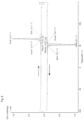
- the phase transition or switching temperatures of the material are determined using differential scanning calorimetry (DSC), see diagram of the Fig.6 . In this measurement, the phase transition that is important for the actuation appears as a peak. From the diagram, it can be seen that in order to switch the actuator, the temperature of the actuator must be increased to at least 67 °C; in order to reset it, the temperature must be reduced to a maximum of 50 °C.
- the shape memory material actuator is in the martensite phase in particular and can be (apparently) plastically deformed by even small forces.
- the shape memory material actuator is in the Fig. 3a shown first position of the movable element.
- the shape memory material actuator can be arranged in the first position in particular so that it is under mechanical tension. However, it can also be relaxed.
- the critical temperatures of the shape memory material actuator are adjustable by passing an electric current I through the shape memory material actuator.
- a voltage supply is provided with which a circuit leading through the shape memory material actuator can be closed optionally for heating ( Fig. 3b ) or to cool the shape memory material actuator ( Fig. 3a ).
- a ball 83b' or a holding element 85a' is inserted between the movable element and the actuator, which centers itself under the X-shaped, pocket-like curved actuator device 85.
- the Figures 3a and 3b show the X-shaped, pocket-like actuator device 85, wherein in Fig. 3a a first position is shown in which the movable element is held in the first position by the return element, e.g. a spring, and wherein in Fig. 3b the second position is shown in which the actuator device 85 was activated and the movable element was deflected to the second position into the stop.
- the actuator device 85 has two shape memory material actuators based on a NiCuTi alloy, namely two elongated, web-shaped shape memory material actuators made from sputtered film, which are arranged crossing each other, i.e. in an X-shape, centrally above the ball of the movable element 83'.
- film-based actuators enables the forces and travel distances to be adjusted by adapting the two-dimensional geometry.
- the surface which is very large in relation to the volume, is retained and ensures rapid heat dissipation or resetting of the actuator in the de-energized state.
- the ends of the shape memory material actuators are connected to the base body 86, 40 or to the circuit board of the microdosing device 80 at the two coupling points 88 ( Fig. 3a ).
- the shape memory material actuators are tensioned above the support point in such a way that the intersection point 85a forms a bending point of the shape memory material actuator.
- a shell-like region of the actuator device is formed, through which the actuator device centers itself above the support point and generates a force directed downwards precisely along the linear movement direction between the first and second position, which results in a correspondingly precise deflection.
- the two shape memory material actuators can be coupled by a connecting member (not shown). While in Fig. 3a to 3c the movable element 83' is constructed from cuboid-shaped sections, it can also be shaped differently, in particular with cylindrical sections, as well as with a ball as a support surface for the actuator device 85.
- the supply voltage is set to 4 V
- the duration of the initial voltage pulse is set to 10 ms
- the pulse width modulation is set to a duty cycle of 1/128, for example.
- the actual switching time is determined, for example, by observing the actuator (or the ball underneath) with a high-speed camera.
- a shape memory material actuator in particular requires less than 2 ms to cover the stroke.
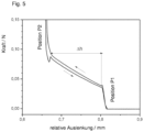
- the force-deflection characteristics of the SMA actuators can be determined using a tensile testing machine.
Landscapes
- Health & Medical Sciences (AREA)
- Clinical Laboratory Science (AREA)
- Chemical & Material Sciences (AREA)
- Chemical Kinetics & Catalysis (AREA)
- Automatic Analysis And Handling Materials Therefor (AREA)
Description
Die Erfindung betrifft eine Mikrodosiereinrichtung zur dosierten Abgabe und/oder Aufnahme von Fluidproben im Mikrovolumenbereich, einem System aus einer solchen Mikrodosiereinrichtung mit einer Pipettiervorrichtung und einem Verfahren zur dosierten Abgabe und/oder Aufnahme von Fluidproben im Mikrovolumenbereich.The invention relates to a microdosing device for the dosed dispensing and/or receiving of fluid samples in the microvolume range, a system comprising such a microdosing device with a pipetting device and a method for the dosed dispensing and/or receiving of fluid samples in the microvolume range.
Pipettiervorrichtungen sind handgehaltene oder automatisierte Laborgeräte, die üblicherweise in medizinischen, biologischen, biochemischen, chemischen und anderen Laboratorien verwendet werden. Sie dienen im Labor der präzisen Dosierung sowie dem Transport von fluiden Proben mit kleinen Volumina und dem Transfer solcher Volumina zwischen unterschiedlichen Probenbehältnissen. Bei Pipettiervorrichtungen werden z.B. flüssige Proben mittels Unterdruck in Pipettenbehälter, z.B. Pipettenspitzen, eingesaugt, dort gelagert, und am Zielort wieder aus diesen abgegeben.Pipetting devices are handheld or automated laboratory devices that are commonly used in medical, biological, biochemical, chemical and other laboratories. They are used in the laboratory for precise dosing and for transporting fluid samples with small volumes and for transferring such volumes between different sample containers. With pipetting devices, for example, liquid samples are sucked into pipette containers, e.g. pipette tips, using negative pressure, stored there, and then dispensed from them again at the destination.
Zu den handgehaltenen Pipettiervorrichtungen gehören z.B. handgehaltene Pipetten und Repetierpipetten, wobei letztere auch als Dispenser bezeichnet werden. Unter einer Pipette wird ein Gerät verstanden, bei dem mittels einer Bewegungseinrichtung, die dem Gerät zugeordnet ist und die insbesondere einen Kolben aufweisen kann, eine zu pipettierende Probe in einen mit der Pipette lösbar verbundenen Pipettierbehälter, insbesondere eine Pipettenspitze, eingesaugt werden kann. Bei einer Luftpolsterpipette ist der Kolben dem Gerät zugeordnet und zwischen der zu pipettierenden Probe und dem Kolbenende befindet sich als druckübertragendes Fluid ein Luftpolster, das beim Aufnehmen der Probe in den Pipettierbehälter unter einem Unterdruck steht, durch den die Probe in den Pipettierbehälter gesaugt wird und/oder im Pipettierbehälter gehalten wird. Unter einem Dispenser wird ein Gerät verstanden, bei dem mittels einer Bewegungseinrichtung, die insbesondere einen Kolben aufweisen kann, ein zu pipettierendes Volumen eines flüssigen Fluids in einen mit dem Dispenser verbundenen Pipettierbehälter, insbesondere eine nach dem Spritzenprinzip ausgestaltete Dispenserspitze, eingesaugt werden kann, wobei die Bewegungseinrichtung zumindest teilweise dem Pipettierbehälter zugeordnet ist, indem z.B. der Kolben im Pipettierbehälter angeordnet ist. Beim Dispenser befindet sich das Kolbenende sehr nahe an der zu pipettierenden Fluidprobe oder in Kontakt mit dieser, weshalb man den Dispenser auch als Direktverdrängerpipette bezeichnet. Pipettiervorrichtungen mit einem als Kolben ausgebildeten Verdrängungselement werden auch als Kolbenhubpipetten bezeichnet.Hand-held pipetting devices include, for example, hand-held pipettes and repeating pipettes, the latter also being referred to as dispensers. A pipette is understood to be a device in which a sample to be pipetted can be sucked into a pipette container, in particular a pipette tip, that is detachably connected to the pipette by means of a movement device that is assigned to the device and which can in particular have a piston. In an air cushion pipette, the piston is assigned to the device and between the sample to be pipetted and the end of the piston there is an air cushion as a pressure-transmitting fluid, which is under a negative pressure when the sample is taken into the pipette container, through which the sample is sucked into the pipette container and/or held in the pipette container. A dispenser is understood to be a device in which a volume of a liquid fluid to be pipetted can be sucked into a pipetting container connected to the dispenser, in particular a dispenser tip designed according to the syringe principle, by means of a movement device, which can in particular have a piston, wherein the movement device is at least partially assigned to the pipetting container, e.g. by arranging the piston in the pipetting container. In the dispenser, the piston end is very close to the fluid sample to be pipetted or in contact with it, which is why the dispenser is also referred to as a direct displacement pipette. Pipetting devices with a displacement element designed as a piston are also referred to as piston-stroke pipettes.
Pipettenspitzen oder Dispenserspitzen bestehen insbesondere aus Kunststoff und können als Einmalartikel nach Gebrauch weggeworfen bzw. durch eine frische Pipettenspitze oder Dispenserspitze ersetzt werden. Sie können aber auch aus Metall oder Glas bestehen oder solches Material aufweisen. Pipettenspitzen oder Dispenserspitze werden in verschiedenen Größen für Dosierungen in verschiedenen Volumenbereichen zur Verfügung gestellt.Pipette tips or dispenser tips are made primarily of plastic and, as disposable items, can be thrown away after use or replaced with a fresh pipette tip or dispenser tip. They can also be made of metal or glass or contain such material. Pipette tips or dispenser tips are available in different sizes for dosing in different volume ranges.
Bei einer Pipettiervorrichtung kann die durch eine einzelne Betätigung abgegebene Probenmenge der in das Gerät aufgesaugten Probenmenge entsprechen. Es kann aber auch vorgesehen sein, dass eine mehreren Abgabemengen entsprechende aufgenommene Probenmenge schrittweise wieder abgegeben wird. Zudem wird zwischen Einkanal-Pipettiervorrichtungen und Mehrkanal-Pipettiervorrichtungen unterschieden, wobei Einkanal-Pipettiervorrichtungen nur einen einzigen Abgabe-/Aufnahmekanal enthalten und Mehrkanal-Pipettiervorrichtungen mehrere Abgabe-/Aufnahmekanäle enthalten, die insbesondere das parallele Abgeben oder Aufnehmen mehrerer Proben erlauben.In a pipetting device, the sample quantity dispensed by a single actuation can correspond to the sample quantity sucked into the device. However, it can also be provided that a sample quantity taken up corresponding to several dispensing quantities is dispensed again step by step. In addition, a distinction is made between single-channel pipetting devices and multi-channel pipetting devices, with single-channel pipetting devices containing only a single dispensing/receiving channel and multi-channel pipetting devices containing several dispensing/receiving channels, which in particular allow the parallel dispensing or aspirating of several samples.
Beispiele für handgehaltene, elektronische Pipettiervorrichtungen bzw. Pipetten sind die Eppendorf Xplorer® und die Eppendorf Xplorer® plus der Eppendorf AG, Deutschland, Hamburg; Beispiele für handgehaltene, elektronische Dispenser sind die Multipette® E3 und Multipette® E3x der Eppendorf AG, Deutschland, Hamburg. Diese Geräte werden, wie auch die Pipettiervorrichtung gemäß der vorliegenden Erfindung, elektrisch betrieben, indem das pipettierende bewegbare Teil, insbesondere der Kolben, durch eine elektrische Motoreinrichtung der Pipettiervorrichtung bewegt wird. Ein Beispiel für einen Pipettierautomaten ist die Eppendorf epMotion®.Examples of handheld, electronic pipetting devices or pipettes are the Eppendorf Xplorer ® and the Eppendorf Xplorer ® plus from Eppendorf AG, Germany, Hamburg; examples of handheld, electronic dispensers are the Multipette ® E3 and Multipette ® E3x from Eppendorf AG, Germany, Hamburg. These devices, like the pipetting device according to the present invention, are operated electrically in that the pipetting movable part, in particular the piston, is moved by an electric motor device of the pipetting device. An example of an automatic pipetting device is the Eppendorf epMotion ® .
Pipettiervorrichtungen dienen der Dosierung und somit der präzisen Abmessung von Flüssigkeitsvolumina. Beim Dosieren sehr kleiner Flüssigkeitsmengen mit Hilfe einer Kolbenhubpipette können die systematischen und zufälligen Fehler der Dosierung beträchtlich anwachsen. Details zum üblichen Vorgehen bei der Fehlerbestimmung und bei der Dosierung kleiner Volumina, insbesondere durch Wandabgabe im Behälter, finden sich in der DIN EN ISO 8655. Bei der Abgabe nach der Freistrahlmethode, bei der die Fluidprobe als Strahl oder freier Tropfen -auch bezeichnet als Jet- den Pipettierbehälter verlässt, können kleinste Volumina zwischen 0,1 µl und 1,0 µl, vorliegend vorzugsweise zusammengefasst unter dem Begriff "Mikrovolumina", mit herkömmlichen Pipettiervorrichtungen nicht mehr ausreichend sicher dosiert werden. Hierfür sind verschiedene physikalische Einflüsse verantwortlich. Zu diesen Einflüssen gehören unter anderem die Bildung von Satellitentropfen durch Reflexion des abgegebenen Volumens an der Flüssigkeitsoberfläche, an der sie auftreffen; der unvollständige Ausstoß des in der Pipettenspitze befindlichen Volumens; die geometrischen Verhältnisse innerhalb der Pipettenspitze; die Oberflächenspannung von Flüssigkeiten und Pipettenspitze und das damit verbundene Benetzungsverhalten bzw. das Auftreten von Kapillarkräften; die elektrostatische Aufladung der Pipettenspitze; eine zu geringe Strömungsgeschwindigkeit bzw. kinetische Energie der Fluidprobe an der Austrittsöffnung der Pipettenspitze. Die Abgabe kleinster Volumina wird zudem dadurch erschwert, dass das Gesamtluftvolumen zwischen Kolben und Probenflüssigkeit als dämpfendes Element hinter dem auszustoßenden Volumen liegt und der effizienten Abgabe eines Freistrahls entgegenwirkt.Pipetting devices are used for dosing and thus for the precise measurement of liquid volumes. When dosing very small amounts of liquid using a piston-operated pipette, systematic and random dosing errors can increase considerably. Details on the usual procedure for determining errors and dosing small volumes, in particular by dispensing from the wall of the container, can be found in DIN EN ISO 8655. When dispensing using the free jet method, in which the fluid sample leaves the pipetting container as a jet or free drop - also known as a jet - the smallest volumes between 0.1 µl and 1.0 µl, preferably summarized here under the term "microvolumes", can no longer be dosed sufficiently safely with conventional pipetting devices. Various physical influences are responsible for this. These influences include, among others, the formation of satellite drops due to reflection of the dispensed volume on the liquid surface on which they hit; the incomplete ejection of the volume in the pipette tip; the geometric conditions within the pipette tip; the surface tension of liquids and pipette tip and the associated wetting behavior or the occurrence of capillary forces; the electrostatic charge of the pipette tip; too low a flow velocity or kinetic energy of the fluid sample at the outlet opening of the pipette tip. The delivery of very small volumes is also made more difficult by the fact that the total air volume between the piston and the sample liquid acts as a damping element behind the volume to be ejected and counteracts the efficient discharge of a free jet.
Um auch Fluidproben mit geringem Volumen im Freistrahl dosiert abgeben zu können, wurden im Stand der Technik verschiedene Ansätze verfolgt.In order to be able to dispense fluid samples with a small volume in a free jet in a metered manner, various approaches have been pursued in the state of the art.
Die
Die
Die
Die
Die
Die
Die
Die genannten Ansätze weisen jeweils bestimmte Nachteile auf und sind insbesondere entweder aufwändig oder voluminös bzw. unflexibel betreffend der Integration in bestehende Laborgeräte, oder zu unpräzise zur Erzeugung der gewünschten Mikrodosiervolumina.The approaches mentioned each have certain disadvantages and are in particular either complex or bulky or inflexible with regard to the integration into existing laboratory equipment, or too imprecise to generate the desired microdosing volumes.
Vor diesem Hintergrund stellt sich die vorliegende Erfindung die Aufgabe, eine effizient gestaltete Mikrodosiereinrichtung zum präzisen Erzeugen eines Mikrodosiervolumens einer Fluidprobe in Form eines Mikrofreistrahls bereitzustellen.Against this background, the present The invention aims to provide an efficiently designed microdosing device for precisely generating a microdosing volume of a fluid sample in the form of a micro free jet.
Die Erfindung löst diese Aufgabe durch die Mikrodosiereinrichtung gemäß Anspruch 1, das System gemäß Anspruch 9 und das Verfahren gemäß Anspruch 12. Bevorzugte Ausgestaltungen sind insbesondere Gegenstände der Unteransprüche.The invention solves this problem by the microdosing device according to
Durch das schlagartige Öffnen des ersten Ventils wird eine sehr effiziente Beschleunigung eines Mikroluftvolumens aus dem ersten Luftkanalabschnitt heraus in den zweiten Luftkanalabschnitt bewirkt, was wiederum effiziente Beschleunigung eines Mikroluftvolumens aus dem zweiten Luftkanalabschnitt und der zweiten Öffnung heraus bewirkt. Auf diese Weise ist die Mikrodosiereinrichtung besonders geeignet zur Erzeugung eines Mikrofludijets, vorliegend auch bezeichnet als Mikrofreistrahl. Ein Mikrofreistrahl ist ein Fluidvolumen im Mikroliterbereich oder Submikroliterbereich, das als Strahl oder freier Tropfen -auch bezeichnet als Jet- die Auslassöffnung eines Fluidkanals oder Fluidtransferbehälters verlässt. Die Dosierung ist insbesondere unabhängig vom Vorgang der Herstellung eines Überdrucks im ersten Luftkanalabschnitt. Da das aus dem ersten Luftkanalabschnitt austretende Mikroluftvolumen die Größe des abgegebenen Mikrodosiervolumens bestimmt, ist ein präzise Dosierung im Mikrovolumenbereich möglich.The sudden opening of the first valve causes a very efficient acceleration of a micro air volume from the first air channel section into the second air channel section, which in turn causes an efficient acceleration of a micro air volume from the second air channel section and the second opening. In this way, the micro dosing device is particularly suitable for generating a micro fluid jet, also referred to here as a micro free jet. A micro free jet is a fluid volume in the microliter range or submicroliter range that leaves the outlet opening of a fluid channel or fluid transfer container as a jet or free drop - also referred to as a jet. The dosing is in particular independent of the process of creating an overpressure in the first air channel section. Since the micro air volume emerging from the first air channel section determines the size of the micro dosing volume delivered, precise dosing in the micro volume range is possible.
Das in der Mikrodosiereinrichtung bewegte Mikroluftvolumen liegt vorzugsweise im Submikroliterbereich, also kleiner als 1 µl. Dementsprechend liegt das von der Mikrodosiereinrichtung abgegebenen Mikrodosiervolumens im Submikroliterbereich. Das als Freistrahl von einer Mikrodosiereinrichtung erzeugte Mikrodosiervolumen entspricht vorzugsweise im Wesentlichen dem -insbesondere von einem Verdrängungselement verdrängten- Mikroluftvolumen, insbesondere ist das Mikrodosiervolumen im Betrag identisch zu dem Mikroluftvolumen. Insbesondere durch wiederholte Abgabe eines Mikrodosiervolumens kann ein durch die sukzessive abgegebenen Mikrodosiervolumina gebildetes Gesamtabgabevolumen auch größer als 1 µl sein, und liegt vorzugsweise im Bereich von 0,1 µl bis 10,0 µl, insbesondere 0,1 µl bis 5,0 µl, insbesondere 0,1 µl bis 2,5 µl, insbesondere 0,1 µl bis 1,5 µl.The micro air volume moved in the micro dosing device is preferably in the submicroliter range, i.e. less than 1 µl. Accordingly, the micro dosing volume delivered by the micro dosing device is in the submicroliter range. The micro dosing volume generated as a free jet by a micro dosing device preferably corresponds essentially to the micro air volume - in particular displaced by a displacement element - and in particular the micro dosing volume is identical in amount to the micro air volume. In particular by repeatedly delivering a micro dosing volume, a total delivery volume formed by the successively delivered micro dosing volumes can also be greater than 1 µl and is preferably in the range from 0.1 µl to 10.0 µl, in particular 0.1 µl to 5.0 µl, in particular 0.1 µl to 2.5 µl, in particular 0.1 µl to 1.5 µl.
In einer bevorzugten Ausgestaltung sind zur Erzeugung des Überdrucks im ersten Luftkanalabschnitt vorgesehen: eine Luftkammer, die mit der ersten Öffnung verbindbar ist oder verbunden ist, ein Verdrängungselement, das zur Verdrängung eines Mikrovolumens (V) der Luftkammer eingerichtet ist, und ein Antrieb, um die Auslenkung des Verdrängungselements anzutreiben, wodurch im ersten Zustand des ersten Ventils der Überdruck im ersten Luftkanalabschnitt erzeugbar ist. Diese Komponenten können Bestandteil der Mikrodosiereinrichtung sein, oder können Bestandteile einer externen Vorrichtung sein, insbesondere einer externen Pipettiervorrichtung, deren Arbeitskonus mit der ersten Öffnung luftdicht verbindbar ist, so dass mittels der externen Pipettiervorrichtung im ersten Zustand des ersten Ventils der Überdruck im ersten Luftkanalabschnitt erzeugbar ist. Da das Mikroluftvolumen (V) durch das vom Verdrängungselement bestimmte Volumen genau festgelegt wird, sind insbesondere keine Drucksensoren in der Luftkammer oder im ersten Luftkanalabschnitt erforderlich, um eine präzise Dosierung zu erreichen.In a preferred embodiment, the following are provided to generate the overpressure in the first air channel section: an air chamber that can be connected or is connected to the first opening, a displacement element that is designed to displace a micro volume (V) of the air chamber, and a drive to drive the deflection of the displacement element, whereby the overpressure can be generated in the first air channel section in the first state of the first valve. These components can be part of the microdosing device, or can be parts of an external device, in particular an external pipetting device whose working cone can be connected to the first opening in an airtight manner, so that the overpressure in the first air channel section can be generated by means of the external pipetting device in the first state of the first valve. Since the micro air volume (V) is precisely determined by the volume determined by the displacement element, in particular no pressure sensors are required in the air chamber or in the first air channel section in order to achieve precise dosing.
Die Pipettiervorrichtung ist vorzugsweise eine -nach dem Luftpolsterprinzip arbeitende-Luftpolsterpipette, insbesondere eine kommerziell erhältliche Pipette oder ein Dispenser, die/der insbesondere zur Steuerung der Mikrodosiereinrichtung angepasst sein kann. Beispiele für derartige kommerziell erhältliche Pipettiervorrichtungen wurden oben genannt. Die Steuerung der Mikrodosiereinrichtung kann aber auch zumindest teilweise oder vollständig in der Mikrodosiereinrichtung angeordnet sein. Sie ist vorliegend eine elektrische Steuereinrichtung der Mikrodosiereinrichtung. Durch Kombination mit einer herkömmlichen Pipette ist die Mikrodosiereinrichtung besonders flexibel einsetzbar.The pipetting device is preferably an air cushion pipette that works according to the air cushion principle, in particular a commercially available pipette or a dispenser that can be adapted in particular to control the microdosing device. Examples of such commercially available pipetting devices were mentioned above. The control of the microdosing device can also be arranged at least partially or completely in the microdosing device. In the present case, it is an electrical control device of the microdosing device. By combining it with a conventional pipette, the microdosing device can be used particularly flexibly.
Vorzugsweise ist die Mikrodosiereinrichtung als Modul ausgebildet. Dazu weist die Mikrodosiereinrichtung vorzugsweise einen Verbindungsabschnitt auf, der mit einem korrespondierenden Verbindungsabschnitt einer externen Pipettiervorrichtung verbindbar -und wieder- lösbar ist. Dieser Verbindung ist vorzugsweise eine formschlüssige Steckund Klemmverbindung, bei der insbesondere der Arbeitskonus einer Pipettiervorrichtung in einen passenden Aufnahmeabschnitt der Mikrodosiereinrichtung eingesteckt wird. Die Steuerung der Mikrodosiereinrichtung kann in diesem Fall über einen Datenaustausch der Mikrodosiereinrichtung mit der Pipettiervorrichtung erfolgen, insbesondere über eine drahtgebundene oder drahtlose Verbindung mit der Pipettiervorrichtung. Die Steuerung kann aber auch unabhängig von der Pipettiervorrichtung erfolgen, und kann insbesondere in die Mikrodosiereinrichtung integriert sein, und kann teilweise manuell steuerbar sein.The microdosing device is preferably designed as a module. For this purpose, the microdosing device preferably has a connecting section that can be connected - and then detached - to a corresponding connecting section of an external pipetting device. This connection is preferably a positive plug and clamp connection, in which in particular the working cone of a pipetting device is inserted into a suitable receiving section of the microdosing device. In this case, the microdosing device can be controlled via a data exchange between the microdosing device and the pipetting device, in particular via a wired or wireless connection with the pipetting device. However, the control can also take place independently of the pipetting device and can in particular be integrated into the microdosing device and can be partially manually controllable.
Das Verdrängungselement ist vorzugsweise ein Kolbenelement, insbesondere ein Kolbenelement einer kommerziell erhältlichen Pipettiervorrichtung. Das Kolbenelement ist vorzugsweise zur Verdrängung von Mikroluftvolumina und von Makroluftvolumina eingerichtet. Ein Makroluftvolumen ist größer als das Mikroluftvolumen. Ein Makroluftvolumen ist insbesondere ein solches Luftvolumen, das typischerweise mit herkömmlichen kommerziell erhältlichen Pipettiervorrichtungen pipettierbar ist. Ein Makroluftvolumen kann demnach insbesondere ein Luftvolumen größer als 2 µl sein, insbesondere kleiner oder gleich 10µl, 50µl, 100µl, 300µl oder 500µl.Vorzugsweise ist die Mikrodosiereinrichtung, oder eine Pipettiervorrichtung, die das Verdrängungselement, insbesondere das Kolbenelement, aufweist, bzw. das Verdrängungselement dazu eingerichtet, im ersten Zustand des ersten Ventils das Mikroluftvolumen (V) zu verdrängen und insbesondere auch dazu eingerichtet, im zweiten Zustand des ersten Ventils ein Makroluftvolumen zu verdrängen.The displacement element is preferably a piston element, in particular a piston element of a commercially available pipetting device. The piston element is preferably designed to displace micro air volumes and macro air volumes. A macro air volume is larger than the micro air volume. A macro air volume is in particular an air volume that can typically be pipetted with conventional commercially available pipetting devices. A macro air volume can therefore in particular be an air volume larger than 2 µl, in particular less than or equal to 10 µl, 50 µl, 100 µl, 300 µl or 500 µl. Preferably, the microdosing device, or a pipetting device that has the displacement element, in particular the piston element, or the displacement element is designed to displace the micro air volume (V) in the first state of the first valve and in particular also designed to displace a macro air volume in the second state of the first valve. to displace.
Die Mikrodosiereinrichtung, und/oder eine mit der ersten Öffnung verbindbare Pipettiervorrichtung, ist vorzugsweise dazu eingerichtet, dass das vom Verdrängungselement zu verdrängende Mikroluftvolumen vom Benutzer auswählbar ist, insbesondere mittels einer Benutzerschnittstelleneinrichtung, die Bestandteil der Mikrodosiereinrichtung oder der Pipettiervorrichtung sein kann.The microdosing device and/or a pipetting device connectable to the first opening is preferably designed so that the micro air volume to be displaced by the displacement element can be selected by the user, in particular by means of a user interface device which can be part of the microdosing device or the pipetting device.
Die erste Öffnung der Mikrodosiereinrichtung ist vorzugsweise mit dem Arbeitskonus einer Pipettiervorrichtung so verbindbar, dass -mittels des Verdrängungselements bzw. mittels der Pipettiervorrichtung- im ersten Luftkanalabschnitt der gewünschte Überdruck einstellbar ist. Dazu kann die Mikrodosiereinrichtung einen Öffnungsabschnitt aufweisen, der die erste Öffnung beinhaltet. Der Öffnungsabschnitt der Mikrodosiereinrichtung kann luftdicht mit einem Öffnungsabschnitt der Luftkammer verbindbar sein, z.B. durch eine formschlüssige Klemmverbindung. Der Öffnungsabschnitt der Luftkammer kann ein Arbeitskonus der Pipettiervorrichtung sein.The first opening of the microdosing device can preferably be connected to the working cone of a pipetting device in such a way that the desired overpressure can be set in the first air channel section by means of the displacement element or by means of the pipetting device. For this purpose, the microdosing device can have an opening section that contains the first opening. The opening section of the microdosing device can be connected in an airtight manner to an opening section of the air chamber, e.g. by means of a positive clamp connection. The opening section of the air chamber can be a working cone of the pipetting device.
Vorzugsweise weist der erste Luftkanalabschnitt eine verschliessbare dritte Öffnung auf, die den ersten Luftkanalabschnitt mit dem Außenraum verbindet, und insbesondere ein steuerbares zweites Ventil auf, das dazu eingerichtet ist, die dritte Öffnung des Luftkanals wahlweise, in einem ersten Zustand, geschlossen zu halten, um den Überdruck im ersten Luftkanalabschnitt gegenüber dem zweiten Luftkanalabschnitt zu ermöglichen, oder, in einem zweiten Zustand, geöffnet zu halten, sowie einen Wechsel vom ersten in den zweiten Zustand zur Herbeiführung eines Druckausgleichs im ersten Luftkanalabschnitt zum Außenraum zu ermöglichen.Preferably, the first air duct section has a closable third opening which connects the first air duct section to the outside space, and in particular a controllable second valve which is designed to keep the third opening of the air duct optionally closed in a first state in order to enable the overpressure in the first air duct section with respect to the second air duct section, or to keep it open in a second state and to enable a change from the first to the second state to bring about a pressure equalization in the first air duct section with the outside space.
Das erste Ventil, insbesondere auch das zweite Ventil oder mindestens ein weiteres Ventil der Mikrodosiereinrichtung oder des Systems weist jeweils vorzugsweise auf: einen Ventilkörper, an dem ein Ventilstößel beweglich angeordnet ist, der mittels mindestens eines FGL-Aktuators des Ventils auslenkbar ist. Der Ventilstößel ist in seinem ersten Zustand insbesondere durch ein Federelement vorgespannt und schließt eine Durchlassöffnung, und ist in seinem zweiten Zustand insbesondere ausgelenkt, wodurch die Durchlassöffnung geöffnet ist. Durch die elektrische Aktivierbarkeit des FGL-Aktuators ist das Ventil steuerbar. Weitere Details des erfindungsgemäßen Ventils können aus der Beschreibung der erfindungsgemäßen Mikrodosiereinrichtung und deren bevorzugten Ausgestaltungen abgeleitet werden.The first valve, in particular also the second valve or at least one further valve of the microdosing device or the system preferably each have: a valve body on which a valve tappet is movably arranged, which can be deflected by means of at least one SMA actuator of the valve. In its first state, the valve tappet is prestressed in particular by a spring element and closes a passage opening, and in its second state is particularly deflected, whereby the passage opening is opened. The valve can be controlled by the electrical activation of the SMA actuator. Further details of the valve according to the invention can be derived from the description of the microdosing device according to the invention and its preferred embodiments.
Das erste Ventil weist einen elektrisch steuerbaren Aktuator auf. Das Ventil, insbesondere der Aktuator, ist für ein schlagartiges Öffnen eingerichtet. Der Aktuator ist ein Formgedächtnislegierungs(FGL)-Aktuator.The first valve has an electrically controllable actuator. The valve, in particular the actuator, is designed for sudden opening. The actuator is a shape memory alloy (SMA) actuator.
Der Erfindung liegen bezüglich dieser Mikrodosiereinrichtung insbesondere Resultate von Messungen an Ventilen mit Aktuatoren aus einer Formgedächtnislegierung zugrunde, die zeigen, dass sich bereits mit sehr kompakt ausgebildeten Formgedächtnismaterial-Aktuatoren sehr präzise und effizient eine Ventilöffnung und damit eine Probenabgabe nach dem Freistrahlprinzip verwirklichen lässt. Formgedächtnislegierungen (FGL) zeigen aufgrund eines Phasenübergangs ein spezielles Verhalten, das als Formgedächtniseffekt bekannt ist. Unterhalb einer materialspezifischen kritischen Temperatur befindet sich ein FGL-Bauteil insbesondere in der Martensit-Phase und lässt sich bereits durch geringe Kräfte (scheinbar) plastisch verformen. Beim Aufheizen auf eine weitere kritische Temperatur wird jedoch innerhalb von Millisekunden die ursprüngliche Bauteilgestalt wiederhergestellt, das Material verhält sich dann wie ein gewöhnliches Metall entsprechend dem Hookschen Gesetz. Von den Erfindern wurde festgestellt, dass sich solche Formgedächtnismaterial-Bauteile aufgrund der mit diesen Bauteilen realisierbaren Kraft-Auslenkungs-Kennlinien besonders zur Erzeugung eines Mikrofluidfreistrahls eignen. Bevorzugte Ausgestaltungen eines Formgedächtnismaterial-Aktuators werden nachfolgend noch beschrieben.With regard to this microdosing device, the invention is based in particular on the results of measurements on valves with actuators made of a shape memory alloy, which show that a valve opening and thus a sample release according to the free jet principle can be achieved very precisely and efficiently with very compact shape memory material actuators. Shape memory alloys (SMA) exhibit a special behavior due to a phase transition, which is known as the shape memory effect. Below a material-specific critical temperature, an SMA component is in the martensite phase in particular and can be (apparently) plastically deformed by even small forces. When heated to a further critical temperature, however, the original component shape is restored within milliseconds, and the material then behaves like a normal metal in accordance with Hooke's law. The inventors found that such shape memory material components are particularly suitable for generating a microfluid free jet due to the force-deflection characteristics that can be realized with these components. Preferred embodiments of a shape memory material actuator are described below.
Ein Aktuator der Mikrodosiereinrichtung ist ein Formgedächtnismaterial-Aktuator.An actuator of the microdosing device is a shape memory material actuator.
Für die Aktuierung werden im Rahmen dieser Erfindung Aktuatoren verwendet, die zumindest abschnittsweise oder vollständig aus einer Formgedächtnislegierung (FGL) bestehen oder diese aufweisen. Diese werden als Formgedächtnismaterial-Aktuatoren oder FGL-Aktuatoren bezeichnet. Im Vergleich zu anderen Aktuatoren besitzen FGL-Aktuatoren eine besonders hohe Energiedichte, so dass bereits sehr kompakte Aktuatoren zum Antrieb der hier definierten Mikrodosiereinrichtungen geeignet sind. Ein weiterer entscheidender Vorteil beim Einsatz der FGL-Aktuatoren, insbesondere gegenüber piezoelektrischen Aktuatoren ist, dass der Betrieb der FGL-Aktuatoren bei einer relativ geringen Spannung erfolgen kann, die insbesonder zwischen 3 V und 10 V, insbesondere bei 5 V liegt. Die erforderlichen Spannungsquellen sind kompakt, so dass sich die vorliegenden Mikrodosiereinrichtungen insbesondere für die Konstruktion portabler Dosiervorrichtungen, insbesondere Pipettiervorrichtungen und Mikrodosiervorrichtungen eignen.For the actuation, actuators are used within the scope of this invention which consist of or comprise at least partially or completely of a shape memory alloy (SMA). These are referred to as shape memory material actuators or SMA actuators. In comparison to other actuators, SMA actuators have a particularly high energy density, so that even very compact actuators are suitable for driving the microdosing devices defined here. Another decisive advantage of using SMA actuators, particularly compared to piezoelectric actuators, is that the SMA actuators can be operated at a relatively low voltage, which is in particular between 3 V and 10 V, in particular 5 V. The required voltage sources are compact, so that the present microdosing devices are particularly suitable for the construction of portable dosing devices, in particular pipetting devices and microdosing devices.
Vorzugsweise weist der Formgedächtnismaterial-Aktuator eine NiTi-Legierung auf oder besteht aus dieser. Eine NiTi-Legierung (auch bekannt unter dem Handelsnamen Nitinol) ist insbesondere biokompatibel. Sie ermöglicht Formänderungen von insbesondere bis zu 8%, wodurch sich insbesondere in effizienter Weise Mikrodosierkammern mit verdrängten Mikrovolumina im Mikroliterbereich und im Submikroliterbereich erzeugen lassen. Besonders bevorzugt weist der Formgedächtnismaterial-Aktuator eine Legierung auf der Basis von TiNiCu auf. Diese ist im Vergleich zum herkömmlichen NiTi besonders ermüdungsresistent und garantiert deshalb insbesondere eine hohe Zuverlässigkeit der Mikrodosiereinrichtung über deren gesamte Lebensdauer. Die Phasenübergangs- oder Schalttemperaturen des Materials lassen sich mittels Dynamischer Differenzkalorimetrie (engl. DSC) bestimmen, siehe
Vorzugsweise werden Film-basierte FGL-Aktuatoren verwendet. Die FGL liegt dabei als Film vor, der eine Dicke zwischen 5 µm und 50 µm, insbesondere zwischen 10 und 30 µm, insbesondere ca. 20 µm aufweist. Diese ermöglicht ein Einstellen der Kräfte und Stellwege durch Anpassung der zweidimensionalen Geometrie. Die im Verhältnis zum Volumen sehr große Oberfläche bleibt dabei erhalten und sorgt für eine schnelle Wärmeabgabe bzw. Rückstellung des FGL-Aktuators im stromlosen Zustand.Preferably, film-based SMA actuators are used. The SMA is in the form of a film with a thickness of between 5 µm and 50 µm, in particular between 10 and 30 µm, in particular around 20 µm. This enables the forces and travel to be adjusted by adapting the two-dimensional geometry. The very large surface area in relation to the volume is retained and ensures rapid heat dissipation or resetting of the SMA actuator when de-energized.
Vorzugsweise ist ein FGL-Aktuator in langgestreckter Form, insbesondere drahtförmig oder stegförmig, und insbesondere aus einem FGL-Film gefertigt, ausgebildet. Die Enden des FGL-Aktuators werden elektrisch kontaktiert. Ein FGL-Aktuator wird vorzugsweise so am Ventil angeordnet, dass die Belastung des FGL-Aktuators im Wesentlichen eine Zugbelastung ist. Ein langgestreckter FGL-Aktuator kann in der nicht-aktivierten Form in einer gekrümmten Geometrie angeordnet werden. Die aktivierte Form kann eine weniger gekrümmte Form oder eine gerade Ausrichtung aufweisen, insbesondere kann der langgestreckte FGL-Aktuator in der aktivierten, geraden Form eine geringere Länge aufweisen als in der nicht aktivierten, stärker gekrümmten Form. Durch die Kontraktion bei Aktivierung kann eine Kraft auf einen Ventilstößel ausgeübt werden, wenn die Enden des Aktuators an einem Basiskörper des Ventils verankert sind. Der FGL-Aktuator wird vorzugsweise so angeordnet, dass der Krümmungsradius stets mindestens dem 50-fachen des Durchmessers senkrecht zur Längsrichtung des langgestreckten Aktuators entspricht, um das Risiko einer Beschädigung des FGL-Aktuators zu reduzieren. Der Durchmesser bzw. die benötigte Stegbreite eines stegförmigen FGL-Aktuators wird vorzugsweise auf den Bedarf an Stellkraft angepasst, der für die Realisierung des gewünschten Ventils erforderlich ist. Kraft-Auslenkungs-Kennlinien von FGL-Aktuatoren sind mittels einer Zugprüfmaschine bestimmbar. Der FGL-Aktuator kann insbesondere auch als Feder geformt sein, insbesondere Schrauben-, Spiral- oder Biegefeder. Eine solche Feder kann in der ersten Position entspannt sein und in der zweiten Position gespannt sein.Preferably, an SMA actuator is designed in an elongated form, in particular wire-shaped or web-shaped, and in particular made of an SMA film. The ends of the SMA actuator are electrically contacted. An SMA actuator is preferably arranged on the valve in such a way that the load on the SMA actuator is essentially a tensile load. An elongated SMA actuator can be arranged in a curved geometry in the non-activated form. The activated form can have a less curved shape or a straight orientation; in particular, the elongated SMA actuator can have a shorter length in the activated, straight form than in the non-activated, more curved form. Due to the contraction upon activation, a force can be exerted on a valve tappet if the ends of the actuator are anchored to a base body of the valve. The SMA actuator is preferably arranged so that the radius of curvature is always at least 50 times the diameter perpendicular to the longitudinal direction of the elongated actuator in order to reduce the risk of damage to the SMA actuator. The diameter or the required web width of a web-shaped SMA actuator is preferably adapted to the actuating force required to create the desired valve. Force-deflection characteristics of SMA actuators can be determined using a tensile testing machine. The SMA actuator can also be shaped as a spring, in particular a helical, spiral or bending spring. Such a spring can be relaxed in the first position and tensioned in the second position.
Das Ventil kann mehr als einen Aktuator aufweisen, insbesondere mindestens zwei Aktuatoren, die zur Auslenkung eines Ventilstößels angeordnet sind. Insbesondere können zwei FGL-Aktuatoren verwendet werden.The valve can have more than one actuator, in particular at least two actuators arranged to deflect a valve tappet. In particular, two SMA actuators can be used.
Mittels des mindestens einen Aktuators bzw. der Aktuatoreinrichtung wird die Auslenkung des Ventilstößels aus einer ersten in eine zweite Position bewirkt, wobei das Ventil in der zweiten Position geöffnet ist, also die Durchlassöffnung des Luftkanals öffnet.By means of the at least one actuator or the actuator device, the deflection of the valve tappet from a first into a second position is effected, wherein the valve is open in the second position, i.e. the passage opening of the air duct opens.
Vorzugsweise weist das Ventil eine Aktuatoreinrichtung auf. Diese weist vorzugsweise einen oder mehrere Aktuatoren auf, darunter jedenfalls einen FGL-Aktuator, insbesondere genau zwei Aktuatoren oder mehr als zwei Aktuatoren, insbesondere FGL-Aktuatoren. Vorzugsweise werden zwei langgestreckte, insbesondere stegförmige, vorzugsweise auf Film-Basis hergestellte FGL-Aktuatoren einander überkreuzend, also kreuzförmig bzw. X-förmig, oberhalb eines Verdrängungselements angeordnet. Die Kreuzungsstelle der FGL-Aktuatoren ist vorzugsweise zentral oberhalb eines Auflageabschnitts des Ventilstößels angeordnet, wobei die Enden der FGL-Aktuatoren an einem Basiskörper des Ventils verankert sind. Die FGL-Aktuatoren sind vorzugsweise oberhalb der Auflagestelle so gespannt, dass die Kreuzungsstelle jeweils eine Krümmungsstelle des FGL-Aktuators bildet. Dadurch wird, wie in den
Falls mehrere FGL-Aktuatoren vorgesehen sind, können diese durch ein Verbindungsglied gekoppelt sein. Dadurch wird die Auslenkung der Aktuatoren weiter synchronisiert und der Kraftvektor der so gebildeten Aktuatoreinrichtung wird beeinflusst. Bei einer X-förmigen Anordnung kann ein Verbindungsglied an der Kreuzungsstelle vorgesehen sein; dadurch wird der bei Kontraktion der FGL-Aktuatoren senkrecht nach unten wirkende Kraftvektor ausgerichtet, und die FGL-Aktuatoren werden an der Kreuzungsstelle in Position gehalten. Das Verbindungsglied kann auch so gestaltet sein, dass die FGL-Aktuatoren einander nicht mechanisch kontaktieren und insbesondere durch das Verbindungsglied elektrisch voneinander isoliert sind.If several SMA actuators are provided, these can be coupled by a connecting link. This further synchronizes the deflection of the actuators and influences the force vector of the actuator device thus formed. In an X-shaped arrangement, a connecting link can be provided at the intersection point; this aligns the force vector acting vertically downwards when the SMA actuators contract, and the SMA actuators are held in position at the intersection point. The connecting link can also be designed so that the SMA actuators do not mechanically contact one another and are in particular electrically isolated from one another by the connecting link.
Vorzugsweise weist die Aktuatoreinrichtung mindestens ein Kopplungselement auf, um den FGL-Aktuator mit dem Ventilstößel und/oder einem Basiskörper des Ventils zu verbinden. Der Ventilstößel ist gegenüber dem Basiskörper insbesondere beweglich angeordnet. Ein FGL-Aktuator kann durch eine oder mehrere Verbindungseinrichtungen mit dem Basiskörper verbunden sein. Insbesondere kann ein FGL-Aktuator mit dem Basiskörper oder mit einem am Basiskörper befestigten Bauteil, z.B. einer Platine des Ventils, stoffschlüssig verbunden sein, insbesondere verlötet sein. Ein FGL-Aktuator ist vorzugsweise gegenüber dem Basiskörper und vorzugsweise gegenüber anderen FGL-Aktuatoren und anderen Teilen elektrisch isoliert, während vorzugsweise seine Enden mit einer Spannungsquelle verbunden bzw. verbindbar sind.The actuator device preferably has at least one coupling element to connect the SMA actuator to the valve tappet and/or a base body of the valve. The valve tappet is arranged in particular so as to be movable relative to the base body. An SMA actuator can be connected to the base body by one or more connecting devices. In particular, an SMA actuator can be integrally connected, in particular soldered, to the base body or to a component attached to the base body, e.g. a circuit board of the valve. An SMA actuator is preferably electrically insulated from the base body and preferably from other SMA actuators and other parts, while its ends are preferably connected or connectable to a voltage source.
Die lineare Bewegung des Ventilstößels erfolgt vorzugsweise so, dass der Ventilstößel bei seiner Auslenkung von der ersten in die zweite Position von der Durchlassöffnung weg bewegt wird, und umgekehrt, bei der Rückbewegung in die erste Position in Richtung der Durchlassöffnung bewegt wird.The linear movement of the valve tappet is preferably carried out in such a way that the valve tappet is moved away from the passage opening when it is deflected from the first to the second position, and conversely, when it is moved back to the first position, it is moved in the direction of the passage opening.
Die Mikrodosiereinrichtung bzw. ein Ventil, insbesondere das erste und/oder das zweite Ventil, weist vorzugsweise einen Basiskörper auf. Der Basiskörper ist vorzugsweise integral gebildet, kann aber auch mehrteilig ausgebildet sein. Er besteht vorzugsweise aus Metall, Kunststoff oder Keramik, oder weist solche Werkstoffe auf. Der Basiskörper bildet insbesondere den Luftkanal aus. Es ist auch bevorzugt, dass der Luftkanal durch mindestens ein rohrförmiges Bauteil gebildet ist. Vorzugsweise weist das Ventil eine Membran auf, die im ersten Zustand des Ventils von einem Ventilstößel ausgelenkt ist und die Durchlassöffnung luftdicht verschließt, um die Ausbildung des Überdrucks in dem ersten Luftkanalabschnitt gegenüber dem zweiten Luftkanalabschnitt zu ermöglichen.The microdosing device or a valve, in particular the first and/or the second valve, preferably has a base body. The base body is preferably integrally formed, but can also be formed in several parts. It preferably consists of metal, plastic or ceramic, or comprises such materials. The base body in particular forms the air channel. It is also preferred that the air channel is formed by at least one tubular component. The valve preferably has a membrane which, in the first state of the valve, is deflected by a valve tappet and seals the passage opening in an airtight manner in order to enable the formation of excess pressure in the first air channel section relative to the second air channel section.
Der Basiskörper kann ein erstes Teil aufweisen, das den Luftkanal bildet. Ein zweites Teil des Basiskörpers kann vorgesehen sein, um mit dem ersten Teil verbunden zu werden. Der zweite Teil kann insbesondere mindestens einen Führungsabschnitt oder Führungskanal aufweisen, um den Ventilstößel bei der Auslenkung zu führen und an einer Längsrichtung des Ventils des Ventils auszurichten. Zwischen dem ersten und zweiten Teil kann die Membran angeordnet werden, insbesondere befestigt werden, insbesondere durch Klemmen zwischen dem ersten und zweiten Teil befestigt werden. Die Membran kann insbesondere die Durchgangsöffnung abdichten und/oder kann insbesondere als Rückstellelement für das Rückstellen des Ventilstößels von der zweiten in die erste Position dienen. Das zweite Teil, oder eine darauf angeordnete Platine, kann insbesondere als Träger für die Aktuatoreinrichtung bzw. den einen oder die mehreren Aktuatoren eingerichtet sein, die insbesondere am zweiten Teil oder der Platine verankert sein können.The base body can have a first part that forms the air channel. A second part of the base body can be provided to be connected to the first part. The second part can in particular have at least one guide section or guide channel to guide the valve tappet during the deflection and to align it with a longitudinal direction of the valve. The membrane can be arranged between the first and second parts, in particular fastened, in particular by clamping between the first and second parts. The membrane can in particular seal the through-opening and/or can in particular serve as a return element for returning the valve tappet from the second to the first position. The second part, or a circuit board arranged thereon, can in particular be designed as a carrier for the actuator device or the one or more actuators, which can in particular be anchored to the second part or the circuit board.
Der Ventilstößel ist insbesondere ein Kolben-artiges Teil. Die Form des Ventilstößels ist vorzugsweise an seine Auslenkung mithilfe einer Führungseinrichtung angepasst. Insbesondere kann der Ventilstößel zylinderförmig sein oder einen oder mehrere zylinderförmige Abschnitte aufweisen.The valve tappet is in particular a piston-like part. The shape of the valve tappet is preferably adapted to its deflection with the aid of a guide device. In particular, the valve tappet can be cylindrical or have one or more cylindrical sections.
Vorzugsweise weist das Ventil eine Membran auf. Eine als Dichtungselement und/oder als Rückstellelement dienende Membran besteht vorzugsweise aus Polydimethylsiloxan (PDMS), insbesondere flexiblen oder hochflexiblem PDMS oder Silikon, oder weist solches Material auf. Die Dicke der Membran beträgt vorzugsweise zwischen 50 µm und 500 µm, vorzugsweise zwischen 100 µm und 300 µm, vorzugsweise zwischen 150 µm und 250 µm, und vorzugsweise etwa 200 µm.The valve preferably has a membrane. A membrane serving as a sealing element and/or as a restoring element preferably consists of polydimethylsiloxane (PDMS), in particular flexible or highly flexible PDMS or silicone, or has such material. The thickness of the membrane is preferably between 50 µm and 500 µm, preferably between 100 µm and 300 µm, preferably between 150 µm and 250 µm, and preferably about 200 µm.
Vorzugsweise weist das Ventil ein Rückstellelement auf, das elastisch verformbar ist und das durch die Auslenkung gespannt wird, und mit dem auf den Ventilstößel eine Rückstellkraft ausübbar ist, um diesen nach der Auslenkung von der ersten Position in die zweite Position zurückzustellen. Insbesondere kann eine als Dichtungselement dienende Membran auch als Rückstellelement dienen. Vorzugsweise ist das Rückstellelement eine Feder, die zwischen Basiskörper und Ventilstößel angeordnet ist. Ferner kann das Rückstellelement ein Aktuator sein, der insbesondere von der elektrischen Steuereinrichtung angesteuert wird. Ein elastisch verformbares Bauteil, insbesondere eine Feder, kann auch als Antriebselement der Auslenkung angeordnet werden, das vom Aktuator gespannt wird - in diesem Fall wird die Durchlassöffnung z.B, durch Lösen einer Rastverbindung, die den Ventilstößel in der ersten Position hält, geöffnet.The valve preferably has a return element that is elastically deformable and that is tensioned by the deflection, and with which a return force can be exerted on the valve tappet in order to return it after the deflection from the first position to the second position. In particular, a membrane serving as a sealing element can also serve as a return element. The return element is preferably a spring that is arranged between the base body and the valve tappet. Furthermore, the return element can be an actuator that is controlled in particular by the electrical control device. An elastically deformable component, in particular a spring, can also be arranged as a drive element for the deflection, which is tensioned by the actuator - in this case, the passage opening is opened, for example, by releasing a locking connection that holds the valve tappet in the first position.
Vorzugsweise weist die Mikrodosiereinrichtung die dritte Öffnung auf, die insbesondere als ein verschließbarer Bypasskanal ausgebildet sein kann, der im geöffneten Zustand den ersten Luftkanalabschnitt mit dem Außenraum verbindet, insbesondere dem Umgebungsdruck. Die dritte Öffnung bzw. der Bypasskanal dient insbesondere zum Ventilieren des ersten Luftkanalabschnitts bzw. zum Druckausgleich des mit dem Bypasskanal fluidisch verbundenen bzw. wahlweise verbindbaren ersten Luftkanalabschnitts.The microdosing device preferably has the third opening, which can be designed in particular as a closable bypass channel which, when opened, connects the first air channel section to the outside space, in particular to the ambient pressure. The third opening or the bypass channel serves in particular for ventilating the first air channel section or for equalizing the pressure of the first air channel section which is fluidically connected to the bypass channel or can be optionally connected.
In weiteren bevorzugten Ausführungsformen ist die Mikrodosiereinrichtung zur wiederholten Abgabe eines Mikrodosiervolumens einer Fluidprobe eingerichtet. Die Mikrodosiereinrichtung kann so als Dispensiervorrichtung bzw. in einem Dispensiermodus betrieben werden. Ein erfindungsgemäßes System weist insbesondere eine erfindungsgemäße Mikrodosiereinrichtung und eine Pipettiervorrichtung auf, und/oder mindestens ein Gerät, mittels dessen Steuereinrichtung die Mikrodosiereinrichtung, insbesondere deren erstes und/oder zweites Ventil steuerbar sind.In further preferred embodiments, the microdosing device is designed for the repeated dispensing of a microdosing volume of a fluid sample. The microdosing device can thus be operated as a dispensing device or in a dispensing mode. A system according to the invention has in particular a microdosing device according to the invention and a pipetting device, and/or at least one device, by means of whose control device the microdosing device, in particular its first and/or second valve, can be controlled.
In bevorzugten Ausführungsformen ist eine erfindungsgemäße Mikrodosiereinrichtung auch zur Aufnahme einer Fluidprobe eingerichtet, indem eine Fluidprobe im zweiten Zustand des ersten Ventils -und falls vorgesehen: im ersten Zustand des zweiten Ventilsdurch das Verdrängungselement in den Fluidtransferbehälter angesaugt wird.In preferred embodiments, a microdosing device according to the invention is also designed to receive a fluid sample by sucking a fluid sample into the fluid transfer container through the displacement element in the second state of the first valve - and if provided: in the first state of the second valve.
Vorzugsweise ist die Mikrodosiereinrichtung als eine Pipettiereinrichtung ausgebildet, mit der über den Fluidkanal eine Fluidprobe ansaugbar und abgebbar ist. Das Ansaugen kann durch ein (herkömmliches) Kolbenelement einer handgehaltenen Kolbenhubpipette bzw. Luftpolsterpipette oder eines Dispensers erfolgen. Vorzugsweise ist die Mikrodosiereinrichtung dazu ausgebildet, dass das Verdrängungselement wahlweise ein Mikroluftvolumen ansaugt oder verdrängt.Preferably, the microdosing device is designed as a pipetting device with which a fluid sample can be sucked in and dispensed via the fluid channel. Suction can be carried out by a (conventional) piston element of a hand-held piston-stroke pipette or air cushion pipette or a dispenser. Preferably, the microdosing device is designed so that the displacement element selectively sucks in or displaces a micro volume of air.
Eine erfindungsgemäße Pipettiervorrichtung, insbesondere eine mit der Mikrodosiereinrichtung versehene kommerzielle Pipettiervorrichtung, zur dosierten Aufnahme und Abgabe von Fluidproben, weist vorzugsweise auf: eine Kolbenkammer, die die Luftkammer bildet, einen in der Kolbenkammer angeordneten, beweglichen Kolben, der das Verdrängungselement bildet, zum Ansaugen von Luft in die Kolbenkammer und zur Abgabe der Luft aus der Kolbenkammer, einen Pipettierkanal, der die Kolbenkammer mit dem Außenraum der Kolbenkammer verbindet. Erfindungsgemäß ist eine derartige Pipettiervorrichtung versehen mit einer erfindungsgemäßen Mikrodosiereinrichtung, deren erste Öffnung mit der Kolbenkammer und/oder dem Pipettierkanal verbindbar ist, so dass von der Pipettiervorrichtung mittels der Mikrodosiereinrichtung ein Mikrodosiervolumen einer Fluidprobe dosierbar und in Form eines Mikrofluidjets über den Pipettierkanal an den Außenraum abgebbar ist.A pipetting device according to the invention, In particular, a commercial pipetting device provided with the microdosing device for the dosed intake and dispensing of fluid samples preferably has: a piston chamber that forms the air chamber, a movable piston arranged in the piston chamber that forms the displacement element, for sucking air into the piston chamber and for dispensing the air from the piston chamber, a pipetting channel that connects the piston chamber to the outside of the piston chamber. According to the invention, such a pipetting device is provided with a microdosing device according to the invention, the first opening of which can be connected to the piston chamber and/or the pipetting channel, so that a microdosing volume of a fluid sample can be dosed by the pipetting device by means of the microdosing device and can be dispensed to the outside in the form of a microfluid jet via the pipetting channel.
Die Erfindung betrifft ferner eine Pipettiervorrichtung mit einer erfindungsgemäßen Mikrodosiereinrichtung zum Erzeugen eines Mikrodosiervolumens einer Fluidprobe in Form eines Mikrofreistrahls, aufweisend eine Luftkammer, ein Verdrängungselement, insbesondere ein Kolbenelement, das zur Auslenkung zwischen einer ersten Position und einer zweiten Position und zum Verdrängen eines Mikrovolumens der Luftkammer eingerichtet ist, wobei die Pipettiervorrichtung vorzugsweise einen Formgedächtnismaterial-Aktuator aufweist, der insbesondere zur Auslenkung des Verdrängungselements angeordnet ist, wobei die Pipettiervorrichtung einen Kolbenantrieb aufweist, insbesondere einen elektrischen Motor, der das Kolbenelement antreibt, wobei die Luftkammer die Kolbenkammer zur Aufnahme des innerhalb der Kolbenkammer beweglich angeordneten Kolbens bildet, so dass insbesondere Kolben und Kolbenkammer nach Art einer konventionellen Kolbenhubpipette oder nach Art eines konventionellen Dispensers arbeiten. Das mittels FGL-Aktuator betriebene erste Ventil erlaubt hier in Kombination mit dem Kolbenantrieb wahlweise eine sehr genaue Mikrodosierung oder eine Dosierung größerer Volumina, wodurch die Pipettiervorrichtung flexibel einsetzbar ist. Wird der Formgedächtnismaterial-Aktuator vorgesehen, kann die Pipettiervorrichtung dazu eingerichtet sein, die Aufnahme und/oder Kompression von Mikrovolumina mittels einer durch den FGL-Aktuator bewirkten Bewegung des Verdrängungselements durchzuführen. Alternativ oder zusätzlich kann die Aufnahme und/oder Kompression der Mikrovolumina durch den Kolbenantrieb bewirkt werden. Im zweiten, geöffneten Zustand des ersten Ventils kann das Pipettieren von insbesondere größeren Volumina (größer gleich 2 µm) mittels des Kolbenantriebs erfolgen, also durch konventionelle Mittel bewirkt werden.The invention further relates to a pipetting device with a microdosing device according to the invention for generating a microdosing volume of a fluid sample in the form of a micro free jet, comprising an air chamber, a displacement element, in particular a piston element, which is designed to deflect between a first position and a second position and to displace a microvolume of the air chamber, wherein the pipetting device preferably has a shape memory material actuator, which is arranged in particular for deflecting the displacement element, wherein the pipetting device has a piston drive, in particular an electric motor, which drives the piston element, wherein the air chamber forms the piston chamber for receiving the piston arranged movably within the piston chamber, so that in particular the piston and piston chamber work in the manner of a conventional piston stroke pipette or in the manner of a conventional dispenser. The first valve operated by means of an SMA actuator allows, in combination with the piston drive, either very precise microdosing or dosing of larger volumes, which means that the pipetting device can be used flexibly. If the shape memory material actuator is provided, the pipetting device can be set up to carry out the absorption and/or compression of microvolumes by means of a movement of the displacement element caused by the SMA actuator. Alternatively or additionally, the absorption and/or compression of the microvolumes can be caused by the piston drive. In the second, open state of the first valve, the pipetting of larger volumes in particular (greater than or equal to 2 µm) can be carried out by means of the piston drive, i.e. by conventional means.
Das Verdrängungselement kann insbesondere mittels eines FGL-Aktuators angetrieben sein, der Bestandteil der Mikrodosiereinrichtung oder der Pipettiervorrichtung sein kann.The displacement element can be driven in particular by means of an SMA actuator, which can be part of the microdosing device or the pipetting device.
Eine typische Verwendung der Mikrodosiereinrichtung liegt in der Dosierung von biologischen, biochemischen, chemischen oder medizinischen Fluidproben in einem Labor.A typical use of the microdosing device is the dosing of biological, biochemical, chemical or medical fluid samples in a laboratory.
Die Mikrodosiereinrichtung, oder die Mikrodosiervorrichtung oder die Pipettiervorrichtung, die eine Mikrodosiereinrichtung aufweist, oder ein externes Gerät weist eine elektrische Steuereinrichtung auf, um das mindestens eine steuerbare Ventil, insbesondere das erste Ventil, das einen FGL-Aktuator aufweist, und/oder das zweite Ventil, insbesondere einen Aktuator bzw. diesen FGL-Aktuator zu steuern. Es handelt sich insbesondere um eine interne Steuereinrichtung, wenn diese nicht in einem externen Gerät angeordnet ist. Die Mikrodosiereinrichtung weist vorzugsweise eine elektrische Spannungsquelle, insbesondere eine Batterie auf, um den Aktuator bzw. den FGL-Aktuator mit Energie zu versorgen. Alternativ oder zusätzlich ist eine Schnittstelle zum Anschluss einer externen Spannungsquelle vorgesehen. Ein externes Gerät oder externes Teil ist kein Bestandteil der Mikrodosiereinrichtung und kann insbesondere durch eine Verbindungseinrichtung, z.B. Kabel, mit der Mikrodosiereinrichtung verbindbar oder verbunden sein. Die Steuereinrichtung ist vorzugsweise dazu eingerichtet, das mindestens eine Ventil zu steuern, insbesondere um die Auslenkung des Ventilstößels von der ersten Position in die zweite Position zu bewirken. Sie kann zusätzlich oder alternativ auch dazu eingerichtet sein, die Auslenkung des Verdrängungselements zu steuern. Dabei ist die Steuereinrichtung vorzugsweise dazu eingerichtet, dass der Aktuator eine Kraft auf den Ventilstößel ausübt, die diesen von der ersten Position in die zweite Position bewegt, insbesondere schlagartig beschleunigt. Vorzugsweise wird der Aktuator von der Steuereinrichtung so gesteuert, dass der Aktuator eine Kraft auf den Ventilstößel auch dann ausübt, nachdem der Ventilstößel die zweite Position erreicht hat, insbesondere an einem Anschlag des Basiskörpers des Ventils anschlägt.The microdosing device, or the microdosing apparatus or the pipetting apparatus which has a microdosing device, or an external device has an electrical control device to control the at least one controllable valve, in particular the first valve which has an SMA actuator, and/or the second valve, in particular an actuator or this SMA actuator. It is in particular an internal control device if it is not arranged in an external device. The microdosing device preferably has an electrical voltage source, in particular a battery, to supply the actuator or the SMA actuator with energy. Alternatively or additionally, an interface is provided for connecting an external voltage source. An external device or external part is not a component of the microdosing device and can be connected or connected to the microdosing device in particular by a connecting device, e.g. cable. The control device is preferably designed to control the at least one valve, in particular to cause the valve tappet to be deflected from the first position to the second position. Additionally or alternatively, it can also be designed to control the deflection of the displacement element. The control device is preferably designed so that the actuator exerts a force on the valve tappet, which moves it from the first position to the second position, in particular accelerates it suddenly. The actuator is preferably controlled by the control device in such a way that the actuator exerts a force on the valve tappet even after the valve tappet has reached the second position, in particular when it strikes a stop on the base body of the valve.
Alternativ kann die Mikrodosiereinrichtung ein elastisch verformbares Antriebselement aufweisen, insbesondere eine Feder, das durch den Aktuator gespannt wird, insbesondere elastisch komprimiert oder expandiert wird, und das durch seine Entspannung die Kraft auf den Ventilstößel ausübt, die diesen von der ersten Position in die zweite Position bewegt. Dabei kann der Ventilstößel in der zweiten Position durch eine Fixierungseinrichtung lösbar fixiert sein, insbesondere verrastet sein. Es kann eine Auslöseeinrichtung vorgesehen sein, um die Fixierung zu lösen, damit das Antriebselement die Auslenkung durchführt.Alternatively, the microdosing device can have an elastically deformable drive element, in particular a spring, which is tensioned by the actuator, in particular elastically compressed or expanded, and which, when relaxed, exerts the force on the valve tappet that moves it from the first position to the second position. The valve tappet can be releasably fixed in the second position by a fixing device, in particular locked. A release device can be provided to release the fixing so that the drive element carries out the deflection.
Die Steuereinrichtung ist insbesondere dazu eingerichtet, die Auslenkung eines FGL-Aktuators von der ersten in die zweite Position zu steuern. Dazu ist der FGL-Aktuator insbesondere an einer ersten Kontaktstelle und einer zweiten Kontaktstelle elektrisch kontaktiert, um bei Anliegen einer elektrischen Spannung zwischen den beiden Kontaktstellen von einem Strom durchflossen zu werden, der den FGL-Aktuator erwärmt, um durch den Formgedächtniseffekt (FGE) die Auslenkung zu bewirken. Die Steuereinrichtung ist insbesondere dazu eingerichtet, um den zeitlichen Verlauf und die Amplitude der am FGL-Aktuator angelegten Spannung vorzugeben. Vorzugsweise ist die Steuereinrichtung dazu eingerichtet, den FGL-Aktuator mit einem sehr kurzen Spannungs- bzw. Stromimpuls zu aktivieren. Die Zeitspanne beträgt vorzugsweise einige 10 Millisekunden (ms), vorzugsweise 1 ms bis 100 ms, vorzugsweise 10 ms bis 100 ms, insbesondere etwa 10 ms. Dadurch wird ein schnelles Auslenken des FGL-Aktuators erreicht. Vorzugsweise ist die Steuereinrichtung dazu eingerichtet, den FGL-Aktuator, insbesondere nach einer Zeitspanne des Aktivierens, durch eine Pulsweitenmodulation anzusteuern. Dies erfolgt insbesondere so, dass die effektive Spannung soweit gedrosselt wird, dass die Schaltposition bzw. die mechanische Spannung des FGL-Aktuators gerade gehalten werden kann.The control device is particularly designed to control the deflection of an SMA actuator from the first to the second position. For this purpose, the SMA actuator is electrically contacted in particular at a first contact point and a second contact point in order to be traversed by a current when an electrical voltage is applied between the two contact points, which heats the SMA actuator in order to cause the deflection by the shape memory effect (FGE). The control device is particularly designed to to specify the time course and the amplitude of the voltage applied to the SMA actuator. The control device is preferably set up to activate the SMA actuator with a very short voltage or current pulse. The time period is preferably a few tens of milliseconds (ms), preferably 1 ms to 100 ms, preferably 10 ms to 100 ms, in particular about 10 ms. This achieves rapid deflection of the SMA actuator. The control device is preferably set up to control the SMA actuator, in particular after a period of activation, by means of pulse width modulation. This is done in particular in such a way that the effective voltage is throttled to such an extent that the switching position or the mechanical tension of the SMA actuator can be kept straight.
Die Steuereinrichtung weist insbesondere eine elektronische Datenverarbeitungseinrichtung auf, insbesondere eine CPU oder einen Mikroprozessor. Die Steuereinrichtung kann programmgesteuert sein, insbesondere mittels Programmparameter, die Zeitpunkt und/oder Art der Auslenkung des Verdrängungselements der Mikrodosiereinrichtung festlegen. Es ist aber auch möglich, die Steuerung der Mikrodosiereinrichtung durch analogelektronische Ansteuerung des Aktuators zu realisieren, also ohne eine Datenverarbeitungseinrichtung.The control device has in particular an electronic data processing device, in particular a CPU or a microprocessor. The control device can be program-controlled, in particular by means of program parameters that determine the time and/or type of deflection of the displacement element of the microdosing device. However, it is also possible to control the microdosing device by analog electronic control of the actuator, i.e. without a data processing device.
Die Mikrodosiereinrichtung, oder die Mikrodosiervorrichtung oder die Pipettiervorrichtung, die eine Mikrodosiereinrichtung aufweist, oder ein externes Gerät, weist vorzugsweise eine Benutzerschnittstelleneinrichtung auf, mit der ein Benutzer die elektrische Steuereinrichtung steuert, insbesondere indem er die zur Steuerung der Mikrodosiereinrichtung verwendeten, insbesondere Steuersignale erzeugenden, Programmparameter durch Benutzereingaben beeinflusst oder indem er, im Fall einer analogelektronischen Steuerung, die Abgabe oder Aufnahme des gewünschten Mikrodosiervolumens und die Erzeugung der Steuersignale auslöst, die den Aktuator des mindestens einen Ventils aktivieren und/oder deaktivieren. Die Benutzerschnittstelleneinrichtung kann jeweils einen oder mehrere elektrische Schalter, Knöpfe und/oder Sensoren aufweisen, und kann Ausgabeeinrichtungen, z.B. Anzeigen, insbesondere ein Display aufweisen.The microdosing device, or the microdosing apparatus or the pipetting apparatus having a microdosing device, or an external device, preferably has a user interface device with which a user controls the electrical control device, in particular by influencing the program parameters used to control the microdosing device, in particular those that generate control signals, through user inputs or by, in the case of an analog electronic control, triggering the dispensing or intake of the desired microdosing volume and the generation of the control signals that activate and/or deactivate the actuator of the at least one valve. The user interface device can each have one or more electrical switches, buttons and/or sensors, and can have output devices, e.g. indicators, in particular a display.
Die Steuereinrichtung kann mindestens eine elektrische Schnittstelle aufweisen, mit der Steuersignale austauschbar sind, insbesondere mit einem externen Gerät austauschbar sind. Insbesondere kann die Steuereinrichtung dazu eingerichtet sein, von einem externen Gerät gesteuert zu werden, so dass die Steuereinrichtung, und damit die Mikrodosiereinrichtung oder Mikrodosiervorrichtung von einem externen Gerät mittels der elektrischen Schnittstelle steuerbar ist. Die Steuereinrichtung kann insbesondere als Steuerungsschnittstelle zwischen der Steuereinrichtung eines externen Geräts und mindestens einer Mikrodosiereinrichtung bzw. einer Mikrodosiervorrichtung ausgebildet sein. Die Steuerungsschnittstelle kann eine elektrische Schaltung aufweisen, um mindestens einen Aktuator der aus mindestens einer Mikrodosiereinrichtung in Abhängigkeit von einem Steuersignal mit Spannung zu beaufschlagen. Das Steuersignal kann dabei von einer internen Steuereinrichtung oder einer externen Steuereinrichtung erzeugt werden. Die Spannungsversorgung für mindestens einen Aktuator aus mindestens einer Mikrodosiereinrichtung kann in die Steuereinrichtung integriert sein oder kann über die mindestens eine elektrische Schnittstelle realisiert werden.The control device can have at least one electrical interface with which control signals can be exchanged, in particular with an external device. In particular, the control device can be set up to be controlled by an external device, so that the control device, and thus the microdosing device or microdosing apparatus, can be controlled by an external device by means of the electrical interface. The control device can in particular be designed as a control interface between the control device of an external device and at least one microdosing device or microdosing apparatus. The control interface can have an electrical circuit in order to supply voltage to at least one actuator from at least one microdosing device depending on a control signal. The control signal can be generated by an internal control device or an external control device. The voltage supply for at least one actuator from at least one microdosing device can be integrated into the control device or can be implemented via the at least one electrical interface.
Die elektrische Schnittstelle kann zum Senden und/oder Empfangen von elektrischen Signalen, insbesondere von Daten, ausgebildet sein. Der Signalaustausch kann über eine drahtgebundene oder drahtlose Verbindungseinrichtung erfolgen. Insbesondere wenn eine interne Steuereinrichtung über eine elektrische Schnittstelle mit dem Gerät, insbesondere der Pipettiervorrichtung, mittels einer Verbindungseinrichtung verbindbar oder temporär verbunden ist, so wird dieses Gerät als externes Gerät bezeichnet.The electrical interface can be designed to send and/or receive electrical signals, in particular data. The signal exchange can take place via a wired or wireless connection device. In particular, if an internal control device can be connected or is temporarily connected to the device, in particular the pipetting device, via an electrical interface by means of a connection device, this device is referred to as an external device.
Das externe Gerät kann eine Pipettiervorrichtung sein, insbesondere eine portable, handgehaltene Pipettiervorrichtung bzw. eine handgehaltene Pipette oder ein handgehaltener Dispenser. Falls die Mikrodosiereinrichtung in eine Piepttiervorrichtung integriert ist, wird die Pipettiervorrichtung nicht als externes Gerät bezeichnet. Die Mikrodosiereinrichtung oder eine Mikrodosiervorrichtung kann ein eigenständiges bzw. autonom arbeitendes Gerät sein, das grundsätzlich ohne Vermittlung eines externen Gerätes betrieben werden kann. Die Mikrodosiereinrichtung kann aber auch als Modul eines externen Gerätes ausgebildet sein. Das Modul ist ein wahlweise mit dem externen Gerät verbindbares, eigenständiges Zubehörteil. Das Modul kann sich dadurch auszeichnen, dass es -insbesondere ausschließlich- in Abhängigkeit vom externen Gerät betrieben wird bzw. betreibbar ist, indem insbesondere eine Steuereinrichtung des externen Geräts die Auslenkung mindestens eines Verdrängungselementes mindestens einer Mikrodosiereinrichtung steuert.The external device can be a pipetting device, in particular a portable, handheld pipetting device or a handheld pipette or a handheld dispenser. If the microdosing device is integrated into a pipetting device, the pipetting device is not referred to as an external device. The microdosing device or a microdosing device can be an independent or autonomously operating device that can basically be operated without the intervention of an external device. However, the microdosing device can also be designed as a module of an external device. The module is an independent accessory that can be optionally connected to the external device. The module can be characterized in that it is operated or can be operated - in particular exclusively - depending on the external device, in particular in that a control device of the external device controls the deflection of at least one displacement element of at least one microdosing device.
Die Erfindung betrifft ferner ein System zum Erzeugen eines Mikrodosiervolumens einer Fluidprobe in Form eines Mikrofreistrahls, beinhaltend eine erfindungsgemäße Mikrodosiereinrichtung und eine konventionelle oder zur Steuerung der Mikrodosiereinrichtung eingerichtete Pipettiervorrichtung, die dazu dient, diesen Überdruck im ersten Luftkanalabschnitt zu erzeugen, wobei die erste Öffnung der Mikrodosiereinrichtung mit einer Luftkammer der Pipettiervorrichtung verbindbar ist oder verbunden ist, die zudem aufweist: ein Verdrängungselement, das zur Verdrängung eines Mikrovolumens (V) der Luftkammer eingerichtet ist, und einen Antrieb, um die Auslenkung des Verdrängungselements anzutreiben, wodurch im ersten Zustand des ersten Ventils der Überdruck im ersten Luftkanalabschnitt erzeugbar ist.The invention further relates to a system for generating a microdosing volume of a fluid sample in the form of a micro free jet, comprising a microdosing device according to the invention and a conventional pipetting device or one configured to control the microdosing device, which serves to generate this overpressure in the first air channel section, wherein the first opening of the microdosing device is connectable or is connected to an air chamber of the pipetting device, which also has: a displacement element configured to displace a microvolume (V) of the air chamber, and a drive to drive the deflection of the displacement element, whereby the overpressure in the first air channel section can be generated in the first state of the first valve.
Die Erfindung betrifft ferner ein Verfahren zum Erzeugen eines Mikrodosiervolumens einer Fluidprobe in Form eines Mikrofreistrahls mittels einer Mikrodosiereinrichtung, insbesondere einer erfindungsgemäßen Mikrodosiereinrichtung, aufweisend den Schritt (Abgabeschritt), dass das erste Ventil so gesteuert wird, dass die Durchlassöffnung mittels des ersten Ventils schlagartig geöffnet wird, wodurch, bedingt durch den Druckausgleich zwischen dem ersten und zweiten Luftkanalabschnitt, ein Mikroluftvolumen aus dem ersten Luftkanalabschnitt austritt und ein Mikroluftvolumen (V) den Luftkanal durch die zweite Öffnung verlässt, so dass ein durch das Mikrovolumen (V) bestimmtes Mikrodosiervolumen der im Fluidtransferbehälter gehaltenen Fluidprobe verdrängt wird und in Form eines Mikrofreistrahls aus dem Fluidtransferbehälter in den Außenraum abgegeben wird.The invention further relates to a method for Generating a microdosing volume of a fluid sample in the form of a micro free jet by means of a microdosing device, in particular a microdosing device according to the invention, comprising the step (dispensing step) that the first valve is controlled such that the passage opening is suddenly opened by means of the first valve, whereby, due to the pressure equalization between the first and second air duct sections, a micro air volume exits the first air duct section and a micro air volume (V) leaves the air duct through the second opening, so that a microdosing volume of the fluid sample held in the fluid transfer container determined by the micro volume (V) is displaced and is released from the fluid transfer container into the outside space in the form of a micro free jet.
Vorzugsweise weist das Verfahren die Schritte auf, dass mittels einer Pipettiervorrichtung, die eine mit der ersten Öffnung verbundene Luftkammer und ein Verdrängungselement aufweist, durch Verdrängung eines Mikrovolumens (V) in der Luftkammer ein Überdruck in dem ersten Luftkanalabschnitt hergestellt wird, bevor der Abgabeschritt erfolgt.Preferably, the method comprises the steps of using a pipetting device having an air chamber connected to the first opening and a displacement element to create an overpressure in the first air channel section by displacing a microvolume (V) in the air chamber before the dispensing step takes place.
Das Verfahren kann Schritte beinhalten, die einem Pipettiervorgang realisieren, d.h. der Abgabe des zuvor aufgenommenen Volumens der Fluidprobe. Das Verfahren kann auch Schritte beinhalten, die einen Dispensiervorgang realisieren, d.h. der schrittweisen Abgabe von Teilvolumina des zuvor aufgenommenen Volumens der Fluidprobe.The method may include steps that implement a pipetting process, i.e. the dispensing of the previously taken volume of the fluid sample. The method may also include steps that implement a dispensing process, i.e. the step-by-step dispensing of partial volumes of the previously taken volume of the fluid sample.
Das erfindungsgemäße Verfahren wird insbesondere bei einer Mikrodosiereinrichtung angewandt, die eine Luftkammer aufweist, die mit der ersten Öffnung verbunden ist, ein Verdrängungselement, das zur Verdrängung eines Mikrovolumens (V) der Luftkammer eingerichtet ist, und einen Antrieb, um die Auslenkung des Verdrängungselements anzutreiben, wodurch im ersten Zustand des ersten Ventils der Überdruck im ersten Luftkanalabschnitt erzeugbar ist.The method according to the invention is applied in particular to a microdosing device which has an air chamber which is connected to the first opening, a displacement element which is designed to displace a microvolume (V) of the air chamber, and a drive to drive the deflection of the displacement element, whereby the overpressure in the first air channel section can be generated in the first state of the first valve.
Das Verfahren wird besondere bei einer Mikrodosiereinrichtung angewandt, bei der der erste Luftkanalabschnitt eine verschließbare dritte Öffnung aufweist, die den ersten Luftkanalabschnitt mit dem Außenraum verbindet, und ein steuerbares zweites Ventil aufweist, das dazu eingerichtet ist, die dritte Öffnung des Luftkanals wahlweise, in einem ersten Zustand, geschlossen zu halten, um den Überdruck im ersten Luftkanalabschnitt gegenüber dem zweiten Luftkanalabschnitt zu ermöglichen, oder, in einem zweiten Zustand, geöffnet zu halten, sowie einen Wechsel vom ersten in den zweiten Zustand zur Herbeiführung eines Druckausgleichs im ersten Luftkanalabschnitt zum Außenraum zu ermöglichen.The method is particularly applied to a microdosing device in which the first air duct section has a closable third opening which connects the first air duct section to the outside space, and has a controllable second valve which is designed to keep the third opening of the air duct optionally closed in a first state in order to enable the overpressure in the first air duct section with respect to the second air duct section, or to keep it open in a second state and to enable a change from the first to the second state to bring about a pressure equalization in the first air duct section with respect to the outside space.
Das Verfahren weist vorzugsweise den Schritt auf, dass ein Fluidprobe, insbesondere eine Flüssigkeit, z.B. eine flüssige Laborprobe, in einen mit der Mikrodosiereinrichtung verbundenen Fluidtransferbehälter, z.B. eine Pipettenspitze, aufgenommen wird. Zur Aufnahme der Fluidprobe wird das Verdrängungselement, insbesondere ein Kolbenelement, von einer ersten in eine zweite Position bewegt.The method preferably comprises the step of receiving a fluid sample, in particular a liquid, e.g. a liquid laboratory sample, in a fluid transfer container, e.g. a pipette tip, connected to the microdosing device. To receive the fluid sample, the displacement element, in particular a piston element, is moved from a first to a second position.
Bei einem Pipettiervorgang sieht das Verfahren zur Aufnahme der Fluidprobe durch Ansaugen vorzugsweise mindestens einen der nachfolgend genannten Schritte vor, insbesondere in dieser Reihenfolge: dass das erste und das zweite Ventil geschlossen sind und das Verdrängungselement in der ersten Position ist; dass das erste Ventil geöffnet wird, um die Durchlassöffnung zu öffnen; dass das Verdrängungselement von der ersten in die zweite Position bewegt wird; dass das erste Ventil und damit die Durchlassöffnung wieder geschlossen wird. Die Fluidprobe, insbesondere mit dem gewünschten Mikrodosiervolumen, ist nun im Fluidtransferbehälter und wird dort durch den leichten Unterdruck/Kapillarkräfte in üblicher Weise gehalten.During a pipetting process, the method for taking up the fluid sample by suction preferably provides for at least one of the following steps, in particular in this order: that the first and second valves are closed and the displacement element is in the first position; that the first valve is opened to open the passage opening; that the displacement element is moved from the first to the second position; that the first valve and thus the passage opening is closed again. The fluid sample, in particular with the desired microdosing volume, is now in the fluid transfer container and is held there in the usual way by the slight negative pressure/capillary forces.
Das Verfahren zur Abgabe der Fluidprobe sieht vorzugsweise mindestens einen der nachfolgend genannten Schritte vor, insbesondere in dieser Reihenfolge: dass das Verdrängungselement sich in der zweiten Position befindet und dass das erste und das zweite Ventil geschlossen sind (Ausgangssituation); dass das Verdrängungselement in die erste Position bewegt wird, während die Ventile geschlossen sind, wodurch das Luftvolumen in Luftkammer und im ersten Luftkanalabschnitt komprimiert wird, so dass der Überdruck erzeugt wird; dass das erste Ventil geöffnet wird, nachdem das Verdrängungselement die erste Position erreicht hat - dadurch entspannt sich die komprimierte Luft sofort und beschleunigt die Fluidprobe mit maximaler Geschwindigkeit. Die Fluidprobe mit dem gewünschten Mikrodosiervolumen tritt aus der Öffnung des Fluidtransferbehälters aus. Vorzugsweise ist auch der Schritt vorgesehen, einen Überhub des Verdrängungselements durchzuführen, um einen "Blowout" des gesamten Restes der im Fluidtransferbehälter eventuell noch enthaltenen Fluidprobe durchzuführen. Dies erfolgt durch weiteres Bewegen (in derselben Richtung des Verdrängungselements, die der Richtung der Bewegung von der zweiten in die erste Position entspricht) des Verdrängungselements aus der ersten Position in eine weitere Abgabe-Position. Alternativ kann der Überhub auch gleich mit dem erstgenannten Abgabeschritt durchgeführt werden, dies bewirkt eine weitere (höhere) Beschleunigung der Fluidprobe.The method for dispensing the fluid sample preferably provides for at least one of the following steps, in particular in this order: that the displacement element is in the second position and that the first and second valves are closed (initial situation); that the displacement element is moved to the first position while the valves are closed, whereby the air volume in the air chamber and in the first air channel section is compressed so that the overpressure is generated; that the first valve is opened after the displacement element has reached the first position - as a result, the compressed air immediately relaxes and accelerates the fluid sample at maximum speed. The fluid sample with the desired microdosage volume exits the opening of the fluid transfer container. Preferably, the step of carrying out an overstroke of the displacement element is also provided in order to carry out a "blowout" of the entire remainder of the fluid sample possibly still contained in the fluid transfer container. This is done by further moving (in the same direction of the displacement element that corresponds to the direction of movement from the second to the first position) the displacement element from the first position to another dispensing position. Alternatively, the overstroke can also be carried out at the same time as the first dispensing step, which causes a further (higher) acceleration of the fluid sample.
Bei einem Dispensiervorgang sieht das Verfahren zur Aufnahme der Fluidprobe durch Ansaugen vorzugsweise mindestens einen der nachfolgend genannten Schritte vor, insbesondere in dieser Reihenfolge: dass das erste und das zweite Ventil geschlossen sind und das Verdrängungselement in der ersten Position ist; dass das erste Ventil geöffnet wird, um die Durchlassöffnung zu öffnen; dass das Verdrängungselement von der ersten in die zweite Position bewegt wird; dass das erste Ventil und damit die Durchlassöffnung wieder geschlossen wird. Die Fluidprobe, insbesondere mit dem gewünschten Gesamtvolumen, ist nun im Fluidtransferbehälter und wird dort durch den leichten Unterdruck/Kapillarkräfte in üblicher Weise gehalten.In a dispensing process, the method for receiving the fluid sample by suction preferably provides for at least one of the following steps, in particular in this order: that the first and the second valve are closed and the displacement element is in the first position; that the first valve is opened in order to open the passage opening; that the displacement element is moved from the first to the second position; that the first valve and thus the passage opening is closed again. The fluid sample, in particular with the desired total volume, is now in the fluid transfer container. and is held there by the slight negative pressure/capillary forces in the usual way.
Das Gesamtvolumen beinhaltet das Dosiervolumen und ein Zusatzvolumen. Mittels des Zusatzvolumens kann ein Restvolumen oder ein Verwerfvolumen vorgesehen werden. Das Restvolumen verbleibt nach Abgabe aller Teilvolumina im Fluidtransferbehälter und stellt sicher, dass auch für den letzten Abgabeschritt mindestens das gewünschte Teilvolumen verfügbar ist. Der Verwerfhub dient dazu, vor der Abgabe der Teilvolumina nach dem Freistrahlprinzip eine erste Abgabemenge gemäß Verwerfhub zu erzeugen, so dass der Meniskus der Fluidprobe an der Abgabeöffnung des Fluidtransferbehälters bei allen darauffolgenden Schritten in gleicher Weise definiert ist-der Meniskus kann bei der ersten Abgabe, also direkt nach der Aufnahme, anders sein als nach einem Abriss gemäß Freistrahlprinzip. Die zweite Position des Verdrängungselements wird insbesondere dem Gesamtvolumen entsprechend eingestellt.The total volume includes the dosing volume and an additional volume. The additional volume can be used to provide a residual volume or a discard volume. The residual volume remains in the fluid transfer container after all partial volumes have been dispensed and ensures that at least the desired partial volume is available for the last dispensing step. The discard stroke is used to generate a first dispensing quantity according to the discard stroke before the partial volumes are dispensed according to the free jet principle, so that the meniscus of the fluid sample at the dispensing opening of the fluid transfer container is defined in the same way in all subsequent steps - the meniscus can be different during the first dispensing, i.e. directly after collection, than after a break according to the free jet principle. The second position of the displacement element is set in particular according to the total volume.
Beim Dispensiervorgang sieht das Verfahren zur Abgabe der Fluidprobe ohne Vorsehen eines Verwerfhubes vorzugsweise mindestens einen der nachfolgend genannten Schritte vor, insbesondere in dieser Reihenfolge: dass das Verdrängungselement sich in der zweiten Position befindet und dass das erste und das zweite Ventil geschlossen sind (Ausgangssituation); dass das zweite Ventil geöffnet wird, wodurch der erste Luftkanalabschnitt ventiliert wird; dass das Verdrängungselement um die Strecke des Zusatzhubes in Richtung der ersten Position bewegt wird, wodurch insbesondere ein mögliches Spiel der Antriebsmechanik kompensiert wird, die das Verdrängungselement antreibt; dass das zweite Ventil wieder geschlossen wird; dass das Verdrängungselement um die Strecke eines gewünschten Teilvolumens in Richtung der ersten Position zu einer Zwischenposition bewegt wird, dadurch wird die Luft im ersten Luftkanalabschnitt komprimiert, so dass der Überdruck erzeugt wird; dass das erste Ventil geöffnet wird, nachdem das Verdrängungselement die Zwischenposition erreicht hat - dadurch entspannt sich die komprimierte Luft sofort und beschleunigt die Fluidprobe mit maximaler Geschwindigkeit, die Fluidprobe mit dem gewünschten Mikrodosier-Teilvolumen tritt hierbei aus der Öffnung des Fluidtransferbehälters aus und das erste Ventil wird dann wieder geschlossen (Abgabe des Teilvolumens); dass der letztgenannte Schritt der Abgabe des Teilvolumens in gewünschter Weise wiederholt wird, beim letzten Abgabeschritt kann sich das Verdrängungselement in der ersten Position befinden. Vorzugsweise ist auch der Schritt vorgesehen, einen Überhub des Verdrängungselements durchzuführen, um einen "Blowout" des gesamten Restvolumens der im Fluidtransferbehälter eventuell noch enthaltenen Fluidprobe durchzuführen. Dies erfolgt durch weiteres Bewegen (in derselben Richtung des Verdrängungselements, die der Richtung der Bewegung von der zweiten in die erste Position entspricht) des Verdrängungselements aus der ersten Position in eine weitere Abgabe-Position.During the dispensing process, the method for dispensing the fluid sample without providing a discard stroke preferably provides for at least one of the following steps, in particular in this order: that the displacement element is in the second position and that the first and second valves are closed (initial situation); that the second valve is opened, whereby the first air channel section is ventilated; that the displacement element is moved by the distance of the additional stroke in the direction of the first position, whereby in particular any possible play in the drive mechanism that drives the displacement element is compensated; that the second valve is closed again; that the displacement element is moved by the distance of a desired partial volume in the direction of the first position to an intermediate position, thereby compressing the air in the first air channel section, so that the overpressure is generated; that the first valve is opened after the displacement element has reached the intermediate position - as a result, the compressed air immediately relaxes and accelerates the fluid sample at maximum speed, the fluid sample with the desired microdosing partial volume emerges from the opening of the fluid transfer container and the first valve is then closed again (dispensing the partial volume); that the last-mentioned step of dispensing the partial volume is repeated as desired, during the last dispensing step the displacement element can be in the first position. Preferably, the step of carrying out an overstroke of the displacement element is also provided in order to carry out a "blowout" of the entire remaining volume of the fluid sample possibly still contained in the fluid transfer container. This is done by further moving (in the same direction of the displacement element that corresponds to the direction of movement from the second to the first position) the displacement element from the first position to a further dispensing position.
Beim Dispensiervorgang sieht das Verfahren zur Abgabe der Fluidprobe mit Vorsehen eines Verwerfhubes vorzugsweise mindestens einen der nachfolgend genannten Schritte vor, insbesondere in dieser Reihenfolge: dass das Verdrängungselement sich in der zweiten Position befindet und dass das erste und das zweite Ventil geschlossen sind (Ausgangssituation); dass das Verdrängungselement um die Strecke des Zusatzhubes in Richtung der ersten Position bis zu einer Ausgangsposition bewegt wird, dadurch wird die Luft im ersten Luftkanalabschnitt komprimiert, so dass der Überdruck erzeugt wird, und es wird insbesondere ein mögliches Spiel der Antriebsmechanik kompensiert, die das Verdrängungselement antreibt; dass das erste Ventil geöffnet wird, nachdem das Verdrängungselement die Ausgangsposition erreicht hat - dadurch entspannt sich die komprimierte Luft sofort und beschleunigt die Fluidprobe mit maximaler Geschwindigkeit, der Verwerfhub verlässt nach dem Freistrahlprinzip den Fluidtransferbehälter und der Meniskus an dessen Abgabeöffnung wird definiert; dass das erste Ventil wieder geschlossen wird; dass das Verdrängungselement um die Strecke eines gewünschten Teilvolumens in Richtung der ersten Position zu einer Zwischenposition bewegt wird, dadurch wird die Luft im ersten Luftkanalabschnitt komprimiert, so dass der Überdruck erzeugt wird; dass das erste Ventil geöffnet wird, nachdem das Verdrängungselement die Zwischenposition erreicht hat - dadurch entspannt sich die komprimierte Luft sofort und beschleunigt die Fluidprobe mit maximaler Geschwindigkeit, die Fluidprobe mit dem gewünschten Mikrodosier-Teilvolumen tritt hierbei aus der Öffnung des Fluidtransferbehälters aus und das erste Ventil wird dann wieder geschlossen (Abgabe des Teilvolumens); dass der letztgenannte Schritt der Abgabe des Teilvolumens in gewünschter Weise wiederholt wird, beim letzten Abgabeschritt kann sich das Verdrängungselement in der ersten Position befinden. Vorzugsweise ist auch der Schritt vorgesehen, einen Überhub des Verdrängungselements durchzuführen, um die Abgabe des letzten Teilvolumens schrittgleich mit dem "Blowout" eines möglichen geringen Restvolumens der im Fluidtransferbehälter eventuell noch enthaltenen Fluidprobe durchzuführen. Dies erfolgt durch weiteres Bewegen (in derselben Richtung des Verdrängungselements, die der Richtung der Bewegung von der zweiten in die erste Position entspricht) des Verdrängungselements aus der ersten Position in eine weitere Abgabe-Position.During the dispensing process, the method for dispensing the fluid sample with provision of a discard stroke preferably provides for at least one of the following steps, in particular in this order: that the displacement element is in the second position and that the first and second valves are closed (initial situation); that the displacement element is moved by the distance of the additional stroke in the direction of the first position to a starting position, thereby compressing the air in the first air channel section so that the overpressure is generated and in particular any possible play in the drive mechanism that drives the displacement element is compensated; that the first valve is opened after the displacement element has reached the starting position - as a result, the compressed air immediately relaxes and accelerates the fluid sample at maximum speed, the discard stroke leaves the fluid transfer container according to the free jet principle and the meniscus at its discharge opening is defined; that the first valve is closed again; that the displacement element is moved by the distance of a desired partial volume in the direction of the first position to an intermediate position, thereby compressing the air in the first air channel section so that the overpressure is generated; that the first valve is opened after the displacement element has reached the intermediate position - as a result, the compressed air immediately relaxes and accelerates the fluid sample at maximum speed, the fluid sample with the desired micro-dosing partial volume emerges from the opening of the fluid transfer container and the first valve is then closed again (dispensing the partial volume); that the last-mentioned step of dispensing the partial volume is repeated in the desired manner, during the last dispensing step the displacement element can be in the first position. Preferably, the step of carrying out an overstroke of the displacement element is also provided in order to carry out the dispensing of the last partial volume at the same time as the "blowout" of a possible small residual volume of the fluid sample possibly still contained in the fluid transfer container. This is done by further moving (in the same direction of the displacement element that corresponds to the direction of movement from the second to the first position) the displacement element from the first position to another discharge position.
Weitere bevorzugte Ausgestaltungen der erfindungsgemäßen Mikrodosiereinrichtung, des Systems und des Verfahrens und weitere Aspekte der Erfindung ergeben sich aus der nachfolgenden Beschreibung der Ausführungsbeispiele in Zusammenhang mit den Figuren. Gleiche Bezugszeichen bezeichnen im Wesentlichen gleiche Bauteile.Further preferred embodiments of the microdosing device according to the invention, the system and the method and further aspects of the invention emerge from the following description of the exemplary embodiments in conjunction with the figures. The same reference numerals designate essentially the same components.
Es zeigen:
-
Fig. 1a zeigt in einer seitlichen Querschnittsansicht eine erfindungsgemäße Mikrodosiereinrichtung gemäß einem ersten Ausführungsbeispiel. -
Fig. 1b zeigt in einer seitlichen Querschnittsansicht ein erfindungsgemäßes Ventil einer Mikrodosiereinrichtung wie inFig. 1a gezeigt, gemäß einem ersten Ausführungsbeispiel. -
Fig. 1c zeigt in einer seitlichen Querschnittsansicht ein zweites Ventil der Mikrodosiereinrichtung ausFig. 1a . -
Fig. 2 zeigt in einer perspektivischen Ansicht die Mikrodosiereinrichtung derFig. 1a . -
Fig. 3a zeigt in einer schematischen Perspektivansicht eine Aktuatoreinrichtung auf Basis einer Formgedächtnislegierung, in einer ersten nicht-ausgelenkten Position. -
Fig. 3b zeigt die Aktuatoreinrichtung derFig. 3a , in einer zweiten ausgelenkten Position. -
Fig. 3c zeigt in einer schematischen Perspektivansicht eine weitere Aktuatoreinrichtung auf Basis einer Formgedächtnislegierung, in einer ersten nicht-ausgelenkten Position. -
Fig. 4 zeigt in einer schematischen Perspektivansicht eine Aktuatoreinrichtung derFig. 3a mit angeschlossener elektrischer Steuereinrichtung. -
Fig. 5 zeigt eine typische Kraft-Auslenkungs-Kennlinie eines FGL-Aktuators, der mit einer erfindungsgemäßen Mikrodosiereinrichtung in einem Ausführungsbeispiel verwendet wird. -
Fig. 6 zeigt ein Diagramm des Ergebnisses einer Dynamischen Differenzkalorimetrie (engl. DSC) zur Bestimmung der Phasenübergangs- oder Schalttemperaturen eines in einer erfindungsgemäßen Mikrodosiereinrichtung gemäß einem Ausführungsbeispiel verwendeten NiTi-Formgedächtnismaterials.
-
Fig. 1a shows in a side cross-sectional view a microdosing device according to the invention according to a first embodiment. -
Fig. 1b shows in a side cross-sectional view a valve according to the invention of a microdosing device as inFig. 1a shown, according to a first embodiment. -
Fig. 1c shows a side cross-sectional view of a second valve of the microdosing device fromFig. 1a . -
Fig.2 shows in a perspective view the microdosing device of theFig. 1a . -
Fig. 3a shows in a schematic perspective view an actuator device based on a shape memory alloy, in a first non-deflected position. -
Fig. 3b shows the actuator device of theFig. 3a , in a second deflected position. -
Fig. 3c shows in a schematic perspective view a further actuator device based on a shape memory alloy, in a first non-deflected position. -
Fig.4 shows in a schematic perspective view an actuator device of theFig. 3a with connected electrical control device. -
Fig.5 shows a typical force-deflection characteristic curve of an SMA actuator which is used with a microdosing device according to the invention in one embodiment. -
Fig.6 shows a diagram of the result of a dynamic differential calorimetry (DSC) for determining the phase transition or switching temperatures of a NiTi shape memory material used in a microdosing device according to the invention according to an embodiment.
Die Mikrodosiereinrichtung 1 und die Pipettiervorrichtung (symbolisiert durch ihren Verbindungsabschnitt 200, 200', bildet ein erfindungsgemäßes System zum Erzeugen eines Mikrodosiervolumens einer Fluidprobe in Form eines Mikrofreistrahls.The
Die Mikrodosiereinrichtung weist eine Kabelverbindung 50 auf, die insbesondere Bestandteil des Systems 400 ist, durch welche die Ventile 31, 32 jeweils mit der elektrischen Steuereinrichtung der Pipettiervorrichtung verbunden sind und dadurch von dieser steuerbar sind. Hier weist die Pipettiervorrichtung (nicht vollständig gezeigt) eine Luftkammer auf, die mit der ersten Öffnung über den Verbindungsabschnitt 200 verbunden ist, ein Verdrängungselement, das zur Verdrängung eines Mikrovolumens (V) der Luftkammer eingerichtet ist, und einen Antrieb, um die Auslenkung des Verdrängungselements anzutreiben, wodurch im ersten Zustand des ersten Ventils der Überdruck im ersten Luftkanalabschnitt erzeugbar ist. Das Mikrovolumen V ist hier identisch mit dem bei einem Pipettiervorgang abzugebenden Mikrodosiervolumen. Das Verdrängungselement der Pipettiervorrichtung ist ein Kolbenelement, das zur vom Anwender auswählbaren Verdrängung von Mikrovolumina und von Volumina größer als 2 µl, und insbesondere kleiner oder gleich 100 µl eingerichtet ist. Die erste Öffnung 21 der Mikrodosiereinrichtung 1 ist mit dem Arbeitskonus 201 der Pipettiervorrichtung über eine Steck-/Klemmverbindung verbindbar, so dass mittels der Pipettiervorrichtung im ersten Luftkanalabschnitt 11 der gewünschte Überdruck einstellbar ist.The microdosing device has a
Die Mikrodosiereinrichtung 1 kann aber auch eine eigene Steuereinrichtung haben (nicht gezeigt), die unabhängig von der Steuereinrichtung der Pipettiervorrichtung arbeitet. In diesem Fall wird der Überdruck im ersten Luftkanalabschnitt durch die Pipettiervorrichtung erzeugt, und der Anwender löst insbesondere die Öffnung des ersten Ventils manuell aus. Die Mikrodosiereinrichtung kann ferner auch so ausgebildet sein (nicht gezeigt), dass diese auch die Luftkammer, z.B. eine Kolbenkammer, das Verdrängungselement, z.B. ein Kolbenelement, und/oder den Antrieb mit optional Antriebsmechanik aufweist. Dadurch wird aus der Mikrodosiereinrichtung eine eigenständige Vorrichtung, die vollständig unabhängig von einer externen Pipettiervorrichtung betreibbar ist.The
Die elektrische Steuereinrichtung, insbesondere eine elektrische Steuereinrichtung der Mikrodosiereinrichtung, ist dazu eingerichtet, das erste Ventil 31 so zu steuern, dass die Durchlassöffnung 14 mittels des ersten Ventils 31 schlagartig geöffnet wird, wodurch, bedingt durch den Druckausgleich zwischen dem ersten 11 und zweiten Luftkanalabschnitt 12, ein Mikroluftvolumen aus dem ersten Luftkanalabschnitt 11 austritt und ein Mikroluftvolumen (V) den Luftkanal 10 durch die zweite Öffnung 22 verlässt, so dass ein durch das Mikroluftvolumen (V) bestimmtes Mikrodosiervolumen der im Fluidtransferbehälter 99 gehaltenen Fluidprobe verdrängt wird und in Form eines Mikrofreistrahls aus dem Fluidtransferbehälter in den Außenraum abgegeben wird.The electrical control device, in particular an electrical control device of the microdosing device, is designed to control the
Der erste Luftkanalabschnitt 11 weist eine verschließbare dritte Öffnung 23 auf, die den ersten Luftkanalabschnitt 11 mit dem Außenraum verbindet, und ein steuerbares zweites Ventil 32, das dazu eingerichtet ist, die dritte Öffnung 23 des Luftkanals 10 wahlweise, in einem ersten Zustand, geschlossen zu halten, um den Überdruck im ersten Luftkanalabschnitt 11 gegenüber dem zweiten Luftkanalabschnitt zu ermöglichen, oder, in einem zweiten Zustand, geöffnet zu halten, sowie einen Wechsel vom ersten in den zweiten Zustand zur Herbeiführung eines Druckausgleichs im ersten Luftkanalabschnitt 11 zum Außenraum zu ermöglichen.The first
Der Luftkanal 10 mit seinem ersten 11 und zweiten 12 Abschnitt ist in einem Basiskörper 40 der Mikrodosiereinrichtung 1 ausgebildet. Der Luftkanal 10 verläuft im Wesentlichen linear. Zur Realisierung der Durchlassöffnung 14 ist der Luftkanal in Höhe der Durchlassöffnung 14 durch eine Wand verschlossen. Durch einen Bypassabschnitt 15, der im Basiskörper ausgebildet ist, wird der erste Abschnitt 11 des Luftkanals 10 zur Durchlassöffnung 14 umgelenkt, von dort beginnt der zweite Luftkanalabschnitt 12, der über den Bypassabschnitt 15 wieder in den linear verlaufenden Bereich übergeht. Die Durchlassöffnung 14 ist durch die Membran 49 verschließbar, wenn diese durch den mittels der Feder gespannten Ventilstößel des ersten Ventils 31 gegen die Durchlassöffnung 14 gepresst wird. Zum Öffnen des Ventils wird der Ventilstößel mittels einer Aktuatoreinrichtung schlagartig ausgelenkt. Die Aktuatoreinrichtung weist zwei kreuzweise angeordnete FGL-Aktuatoren auf, deren Kreuzungspunkt oberhalb des Ventilstößels zentriert ist. Die Aktivierung dieser Aktuatoren mittels dem von der Steuereinrichtung gesteuertem Strom wird aufrecht erhalten, solange die Öffnung des Ventils gewünscht oder vorbestimmt ist.The
Der Rahmen Y markiert das zweite Ventil 32, das dem Ventilieren des ersten Luftkanalabschnitts dient. In
Die Ventile 31, 32 weisen jeweils, wie anhand des Ventils 31 in
In der
Eine Kontraktion des Formgedächtnismaterial-Aktuator 85 führt dazu, siehe
Das Formgedächtnismaterial-Aktuator ist eine Legierung auf Basis von TiNiCu, die im Vergleich zum herkömmlichen NiTi noch ermüdungsresistenter ist und damit eine vorteilhafte Langzeitstabilität und Zuverlässigkeit des Formgedächtnismaterial-Aktuators bietet. Die Phasenübergangs- oder Schalttemperaturen des Materials werden mittels Dynamischer Differenzkalorimetrie (engl. DSC) bestimmt, siehe Diagramm der
Die
Die Enden der Formgedächtnismaterial-Aktuatoren sind am Basiskörper 86, 40 bzw. an der Platine der Mikrodosiereinrichtung 80 jeweils an den beiden Kopplungsstellen 88 (
Die Membran 49 besteht aus hochflexiblem PDMS der Dicke 200 µm und ist im stromlosen Zustand der Formgedächtnismaterial-Aktuatoren vorausgelenkt, um die Ventilöffnung zu schließen.The
Die Aktuatoren der Aktuatoreinrichtung 85 sind beispielsweise jeweils paarweise auf eine Trägerplatte bzw. Platine mit integrierten Leiterbahnen aufgebracht und elektrisch kontaktiert, siehe
Für ein möglichst schnelles Schalten der Formgedächtnismaterial-Aktuatoren werden die Versorgungsspannung auf 4 V, die Dauer des initialen Spannungspulses auf 10 ms, sowie die Pulsweitenmodulation beispielsweise auf einen Duty Cycle von 1/128 eingestellt. Die tatsächliche Schaltzeit wird z.B. durch Beobachtung des Aktors (bzw. der darunterliegenden Kugel) mit einer Hochgeschwindigkeitskamera bestimmt. Ein Formgedächtnismaterial-Aktuator benötigt insbesondere weniger als 2 ms für das Zurücklegen des Hubes. Die Kraft-Auslenkungs-Kennlinien der FGL-Aktuatoren lassen sich mittels einer Zugprüfmaschine bestimmen.To ensure that the shape memory material actuators switch as quickly as possible, the supply voltage is set to 4 V, the duration of the initial voltage pulse to 10 ms, and the pulse width modulation is set to a duty cycle of 1/128, for example. The actual switching time is determined, for example, by observing the actuator (or the ball underneath) with a high-speed camera. A shape memory material actuator in particular requires less than 2 ms to cover the stroke. The force-deflection characteristics of the SMA actuators can be determined using a tensile testing machine.
Die Steuerung dieser Verfahren zum Betreiben des Moduls 1 sind vorzugsweise durch eine in gewünschter Weise eingerichtete, insbesondere programmierte, elektrische Steuereinrichtung 350 implementiert (
Claims (15)
- Microdosing device (1) for generating a microdosing volume of a fluid sample in the form of a microjet, comprisingan air duct (10) that comprises a passage opening (14), which connects a first air duct section (11) and a second air duct section (12) of the air duct, wherein the first air duct section (11) comprises a first opening (21) and the second air duct section (12) comprises a second opening (22), to which a fluid transfer container (99) containing the fluid sample can be connected,a controllable first valve (31) that is configured to selectively keep the passage opening (14) of the air duct (10) in a first state closed, in order to allow for an overpressure in the first air duct section (11) relative to the second air duct section (12), or in a second state open, and to allow for an abrupt switching from the first to the second state,an electric control device,in which the electrical control device is configured to control said first valve (31) in such a way that said passage opening (14) is opened abruptly by means of the first valve, whereby, due to the pressure equalization between said first (11) and said second air duct (12), a microvolume of air exits the first air duct section and a microvolume of air (V) exits said air duct (10) through said second opening (22), so that a microdosing volume, with that volume being determined by the microvolume of air (V), of the fluid sample contained in the fluid transfer container (99) is displaced and emitted in the form of a microjet from the fluid transfer container into an external volume,wherein the first valve (31) comprises a shape-memory alloy (SMA) actuator.
- Microdosing device according to claim 1, in which the first opening of the microdosing device can be connected to an air chamber of a pipetting apparatus.
- Microdosing device according to claim 1, in which the microdosing device comprises an air chamber that is connected to the first opening, a displacement element that is configured for displacing a microvolume (V) of the air chamber, and a drive system for driving the deflection of the displacement element, whereby an overpressure can be generated in said first air duct section when said first valve is in said first state.
- Microdosing device according to claim 3, in which the displacement element is a piston element that is configured to displace the microvolume (V) when the first valve (31) is in the first state, and that is configured to displace a macrovolume of air when the first valve is in the second state.
- Microdosing device according to any one of the preceding claims, in which the first opening of the microdosing device can be connected to the nose cone of a pipetting apparatus, so that the desired overpressure can be adjusted in the first air duct section by means of the pipetting apparatus.
- Microdosing device according to any one of the preceding claims, in which the first air duct section comprises a closable third opening (23) that connects said first air duct section with the external volume, and a controllable second valve (32) that is configured to selectively keep the third opening of the air duct in a first state - closed - in order to allow for the overpressure in the first air duct section relative to the second air duct section, or in a second state - open -, and to allow for switching from the first to the second state in order to achieve a pressure equalization between the first air duct section and the external volume.
- Microdosing device according to any one of the preceding claims, in which the second valve comprises a SMA actuator.
- Microdosing device according to any one of the preceding claims that comprises an electrical control device, which is configured to control said first valve (31) such that said passage opening (14) is opened abruptly by means of said first valve, whereby, due to the pressure equalization between said first (11) and said second air duct section (12), a microvolume of air exits said first air duct section and a microvolume of air (V) exits said air duct (10) through the second opening (22), so that a microdosing volume, with that volume being determined by the microvolume of air (V), of the fluid sample contained in the fluid transfer container (99) is displaced and emitted in the form of a microjet from the fluid transfer container into the external space.
- System (400) for generating a microdosing volume of a fluid sample in the form of a microjet, comprising a microdosing device according to any one of the preceding claims and a pipetting apparatus, which has the purpose of generating said overpressure in said first air duct section, in which the first opening of the microdosing device can be connected or is connected to an air chamber of the pipetting apparatus, and which comprises furthermore: a displacement element that is configured to displace a microvolume (V) of the air chamber, and a drive system for driving the deflection of said displacement element, whereby an overpressure can be generated in said first air duct section when said first valve is in said first state.
- System according to claim 9, in which the pipetting apparatus is in particular a commercially available pipetting apparatus, in which the pipetting apparatus comprises an electrical control device that is configured to control the first valve (31) in such a way that the passage opening (14) is opened abruptly by means of said first valve whereby, due to the pressure equalization between said first (11) and said second air duct section (12), a microvolume of air exits said first air duct section and a microvolume of air (V) exits said air duct (10) through the second opening (22), so that a microdosing volume, with that volume being determined by the microvolume of air (V), of the fluid sample contained in the fluid transfer container (99) is displaced and emitted in the form of a microjet from the fluid transfer container into the external space.
- System according to claim 9 or 10, comprising a cable connection that connects the microdosing device with an electrical control device of the pipetting apparatus, so that said at least one valve of the microdosing device can be controlled by the electrical control device, in particular for controlling said first valve (31) such that the passage opening (14) is opened abruptly by means of said first valve, whereby, due to the pressure equalization between said first (11) and said second air duct section (12), a microvolume of air exits said first air duct section and a microvolume of air (V) exits said air duct (10) through the second opening (22), so that a microdosing volume, with that volume being determined by the microvolume of air (V), of the fluid sample contained in the fluid transfer container (99) is displaced and emitted in the form of a microjet from the fluid transfer container into the external space.
- Procedure (500) for generating a microdosing volume of a fluid sample in form of a microjet by means of a microdosing device according to any one of the preceding claims, comprising the step (release step) of controlling said first valve such that the passage opening is opened abruptly by means of said first valve, whereby, due to the pressure equalization between the first and the second air duct section, a microvolume of air exits said first air duct section and a microvolume of air (V) exits said air duct (10) through the second opening, so that a microdosing volume, with that volume being determined by the microvolume of air (V), of the fluid sample contained in the fluid transfer container is displaced and emitted in the form of a microjet from the fluid transfer container into the external space.
- Procedure according to claim 12, comprising the steps of generating an overpressure in the first air duct section by means of a pipetting apparatus, which comprises an air chamber connected to the first opening and a displacement element, and with the overpressure being generated by displacing a microvolume (V) in the air chamber before the release step occurs.
- Procedure according to claim 12 or 13, comprising steps that serve for the uptake and/or the release of a fluid sample in a pipetting- or dispensing process.
- Usage of the microdosing device according to any one of the claims 1 through 8, of the system according to any one of the claims 9 through 11, or of the procedure according to any one of the claims 12 through 14 for generating a microdosing volume of a laboratory sample in a jet, in particular of an aqueous laboratory sample, in particular of a biological, medical, chemical, biochemical, pharmaceutical, or forensic sample.
Priority Applications (2)
| Application Number | Priority Date | Filing Date | Title |
|---|---|---|---|
| EP17202368.1A EP3485974B2 (en) | 2017-11-17 | 2017-11-17 | Microdosing device for dosing minute fluid samples |
| PCT/EP2018/081558 WO2019096993A1 (en) | 2017-11-17 | 2018-11-16 | Micrometering device for the metering of very small fluid samples |
Applications Claiming Priority (1)
| Application Number | Priority Date | Filing Date | Title |
|---|---|---|---|
| EP17202368.1A EP3485974B2 (en) | 2017-11-17 | 2017-11-17 | Microdosing device for dosing minute fluid samples |
Publications (3)
| Publication Number | Publication Date |
|---|---|
| EP3485974A1 EP3485974A1 (en) | 2019-05-22 |
| EP3485974B1 EP3485974B1 (en) | 2021-09-15 |
| EP3485974B2 true EP3485974B2 (en) | 2024-07-10 |
Family
ID=60629409
Family Applications (1)
| Application Number | Title | Priority Date | Filing Date |
|---|---|---|---|
| EP17202368.1A Active EP3485974B2 (en) | 2017-11-17 | 2017-11-17 | Microdosing device for dosing minute fluid samples |
Country Status (2)
| Country | Link |
|---|---|
| EP (1) | EP3485974B2 (en) |
| WO (1) | WO2019096993A1 (en) |
Families Citing this family (2)
| Publication number | Priority date | Publication date | Assignee | Title |
|---|---|---|---|---|
| EP3838412A1 (en) | 2019-12-20 | 2021-06-23 | MT.DERM GmbH | Device and method for the dosed delivery of a microfluidic fluid quantity in the picoliter and microlitter region and a hand tool for local puncturing of a human or animal skin |
| KR102572756B1 (en) * | 2020-11-20 | 2023-08-30 | 바디텍메드(주) | A socket for for capillary tip desorption |
Citations (6)
| Publication number | Priority date | Publication date | Assignee | Title |
|---|---|---|---|---|
| EP0257353B1 (en) † | 1986-08-14 | 1990-11-14 | Kontron Instruments Holding N.V. | Pipetting device |
| US5158748A (en) † | 1990-01-18 | 1992-10-27 | Mochida Pharmaceutical Co., Ltd. | Automated dispensing and diluting system |
| DE29713744U1 (en) † | 1997-08-01 | 1998-12-03 | Planatol Klebetechnik GmbH, 83101 Rohrdorf | Glue and / or moistening device |
| EP1150105A2 (en) † | 2000-04-28 | 2001-10-31 | Eppendorf Ag | Microdosing system with gas cushion |
| DE10238564A1 (en) † | 2002-08-22 | 2004-03-11 | Fraunhofer-Gesellschaft zur Förderung der angewandten Forschung e.V. | Pipetting device and method for operating a pipetting device |
| DE102008016549A1 (en) † | 2008-03-27 | 2009-11-19 | Nyársik, Lajos, Dr. | Dosing apparatus for contact free dispensing of liquids, has channel module for collecting and dispensing liquid by capillary and regulated pressure system for generation of over pressure |
Family Cites Families (14)
| Publication number | Priority date | Publication date | Assignee | Title |
|---|---|---|---|---|
| AU2519184A (en) | 1983-03-21 | 1984-09-27 | Miles Laboratories Inc. | Microdroplet dispensing apparatus |
| US5763278A (en) | 1995-11-01 | 1998-06-09 | Tecan Ag | Automated pipetting of small volumes |
| DE19737173B4 (en) | 1997-08-26 | 2007-04-05 | Eppendorf Ag | micro-dosing system |
| DE19802368C1 (en) | 1998-01-22 | 1999-08-05 | Hahn Schickard Ges | Microdosing device |
| CH695544A5 (en) | 2000-11-17 | 2006-06-30 | Tecan Trading Ag | Apparatus for dispensing or aspirating / dispensing liquid samples. |
| DE10220371A1 (en) | 2002-05-07 | 2003-11-27 | Fraunhofer Ges Forschung | Free jet metering module and method for its production |
| DE10337484B4 (en) | 2003-08-14 | 2005-05-25 | Zengerle, Roland, Prof. Dr. | Microdosing device and method for the metered dispensing of liquids |
| GB0418256D0 (en) * | 2004-08-16 | 2004-09-15 | The Technology Partnership Plc | Liquid dispensing device |
| TWI286086B (en) * | 2005-04-11 | 2007-09-01 | Unaxis Int Trading Ltd | Method for operating a pneumatic device for the metered delivery of a liquid and pneumatic device |
| DE102007010412B4 (en) * | 2007-02-13 | 2020-07-30 | Endress+Hauser Conducta Gmbh+Co. Kg | Device and method for dosing liquids into gas-filled rooms |
| DE102010038414A1 (en) * | 2010-07-26 | 2012-01-26 | Hamilton Bonaduz Ag | Pipetting device with throttle point in the pipetting channel |
| EP2662137A1 (en) | 2012-05-08 | 2013-11-13 | Roche Diagniostics GmbH | Dispensing assembly |
| DE102012209314B4 (en) * | 2012-06-01 | 2015-04-02 | Albert-Ludwigs-Universität Freiburg | Device and method for dispensing or receiving a liquid volume |
| US9221046B2 (en) | 2014-01-30 | 2015-12-29 | Rainin Instrument, Llc | Air displacement pipette with enhanced blowout |
-
2017
- 2017-11-17 EP EP17202368.1A patent/EP3485974B2/en active Active
-
2018
- 2018-11-16 WO PCT/EP2018/081558 patent/WO2019096993A1/en not_active Ceased
Patent Citations (6)
| Publication number | Priority date | Publication date | Assignee | Title |
|---|---|---|---|---|
| EP0257353B1 (en) † | 1986-08-14 | 1990-11-14 | Kontron Instruments Holding N.V. | Pipetting device |
| US5158748A (en) † | 1990-01-18 | 1992-10-27 | Mochida Pharmaceutical Co., Ltd. | Automated dispensing and diluting system |
| DE29713744U1 (en) † | 1997-08-01 | 1998-12-03 | Planatol Klebetechnik GmbH, 83101 Rohrdorf | Glue and / or moistening device |
| EP1150105A2 (en) † | 2000-04-28 | 2001-10-31 | Eppendorf Ag | Microdosing system with gas cushion |
| DE10238564A1 (en) † | 2002-08-22 | 2004-03-11 | Fraunhofer-Gesellschaft zur Förderung der angewandten Forschung e.V. | Pipetting device and method for operating a pipetting device |
| DE102008016549A1 (en) † | 2008-03-27 | 2009-11-19 | Nyársik, Lajos, Dr. | Dosing apparatus for contact free dispensing of liquids, has channel module for collecting and dispensing liquid by capillary and regulated pressure system for generation of over pressure |
Also Published As
| Publication number | Publication date |
|---|---|
| WO2019096993A1 (en) | 2019-05-23 |
| EP3485974A1 (en) | 2019-05-22 |
| EP3485974B1 (en) | 2021-09-15 |
Similar Documents
| Publication | Publication Date | Title |
|---|---|---|
| EP1654068B1 (en) | Microdosing device and method for the dosed delivery of liquids | |
| DE69931787T2 (en) | Device and method for administration of drops | |
| DE60317305T2 (en) | CONTACTLESS METHOD FOR DISTRIBUTING LOW LIQUID QUANTITIES | |
| EP1344028B1 (en) | Pipette system and pipette array | |
| EP3573758B1 (en) | Pipetting device for pulsed pipetting with a pipetting piston movement regulated on the basis of a determination of the working gas pressure | |
| EP3554706B1 (en) | Pipetting device for an improved pulse-based pipetting of liquid | |
| EP2633914B2 (en) | Pipetting device and method for its production | |
| EP2165769A2 (en) | Discharge device | |
| EP1173279B1 (en) | Method and device for applying small quantities of liquid | |
| EP1333926B1 (en) | Device and system for dispensing or aspirating/dispensing liquid samples | |
| EP3485974B2 (en) | Microdosing device for dosing minute fluid samples | |
| EP2163902B1 (en) | Method and metering device for metering a fluid into a receptacle channel of a testing element for bodily fluid analysis | |
| DE102013013545B4 (en) | Vacuum generating device | |
| EP2086689B1 (en) | Valve unit for interrupting or releasing a flow of a medium along a hollow duct, use thereof in a dosing system for the metered discharge of said medium, and method for the metered discharge of a medium | |
| EP1707269B1 (en) | Pipetting device | |
| EP3450020B1 (en) | Microdosing device for dosing minute fluid samples | |
| EP3972736A1 (en) | Liquid screening assembly with mechanical release of very small liquid quantities | |
| EP3890888A2 (en) | Liquid-metering device for ballistically discharging metered amounts in the nanoliter range, liquid-metering method and pipetting tip therefor | |
| EP3393664B1 (en) | Pipetting device and method for producing same | |
| EP4164798A1 (en) | Pipetting device with gas-sound-triggered dispensing of fluid amounts preferably in the range of 10 to 500 nl | |
| DE102009037105A1 (en) | Pressure dispenser for dispensing drops and series of drops of fluid material, has media container with chamber that is connected with capillary, and pressure source subjecting chamber with gas pressure for dispensing drop of fluid material | |
| DE102023208320A1 (en) | Microdosing device and method for dispensing drops from a plurality of nozzles | |
| DE102013200302A1 (en) | Dosing system useful for contactless dispensing of small quantities of liquid comprises metering chamber with region having deflectable wall and outlet opening for liquid to be metered, and mechanical actuator with deflectable wall |
Legal Events
| Date | Code | Title | Description |
|---|---|---|---|
| PUAI | Public reference made under article 153(3) epc to a published international application that has entered the european phase |
Free format text: ORIGINAL CODE: 0009012 |
|
| STAA | Information on the status of an ep patent application or granted ep patent |
Free format text: STATUS: THE APPLICATION HAS BEEN PUBLISHED |
|
| AK | Designated contracting states |
Kind code of ref document: A1 Designated state(s): AL AT BE BG CH CY CZ DE DK EE ES FI FR GB GR HR HU IE IS IT LI LT LU LV MC MK MT NL NO PL PT RO RS SE SI SK SM TR |
|
| AX | Request for extension of the european patent |
Extension state: BA ME |
|
| STAA | Information on the status of an ep patent application or granted ep patent |
Free format text: STATUS: REQUEST FOR EXAMINATION WAS MADE |
|
| 17P | Request for examination filed |
Effective date: 20191112 |
|
| RBV | Designated contracting states (corrected) |
Designated state(s): AL AT BE BG CH CY CZ DE DK EE ES FI FR GB GR HR HU IE IS IT LI LT LU LV MC MK MT NL NO PL PT RO RS SE SI SK SM TR |
|
| STAA | Information on the status of an ep patent application or granted ep patent |
Free format text: STATUS: EXAMINATION IS IN PROGRESS |
|
| 17Q | First examination report despatched |
Effective date: 20200804 |
|
| GRAP | Despatch of communication of intention to grant a patent |
Free format text: ORIGINAL CODE: EPIDOSNIGR1 |
|
| STAA | Information on the status of an ep patent application or granted ep patent |
Free format text: STATUS: GRANT OF PATENT IS INTENDED |
|
| INTG | Intention to grant announced |
Effective date: 20210315 |
|
| GRAS | Grant fee paid |
Free format text: ORIGINAL CODE: EPIDOSNIGR3 |
|
| RIN1 | Information on inventor provided before grant (corrected) |
Inventor name: GUELTIG, MARCEL Inventor name: OSSMER, HINNERK Inventor name: MOLITOR, PETER |
|
| RIN1 | Information on inventor provided before grant (corrected) |
Inventor name: GUELTIG, MARCEL Inventor name: OSSMER, HINNERK Inventor name: MOLITOR, PETER |
|
| GRAA | (expected) grant |
Free format text: ORIGINAL CODE: 0009210 |
|
| STAA | Information on the status of an ep patent application or granted ep patent |
Free format text: STATUS: THE PATENT HAS BEEN GRANTED |
|
| AK | Designated contracting states |
Kind code of ref document: B1 Designated state(s): AL AT BE BG CH CY CZ DE DK EE ES FI FR GB GR HR HU IE IS IT LI LT LU LV MC MK MT NL NO PL PT RO RS SE SI SK SM TR |
|
| REG | Reference to a national code |
Ref country code: CH Ref legal event code: EP |
|
| RIN1 | Information on inventor provided before grant (corrected) |
Inventor name: GUELTIG, MARCEL Inventor name: OSSMER, HINNERK Inventor name: MOLITOR, PETER |
|
| REG | Reference to a national code |
Ref country code: DE Ref legal event code: R096 Ref document number: 502017011494 Country of ref document: DE |
|
| REG | Reference to a national code |
Ref country code: IE Ref legal event code: FG4D Free format text: LANGUAGE OF EP DOCUMENT: GERMAN |
|
| REG | Reference to a national code |
Ref country code: AT Ref legal event code: REF Ref document number: 1430115 Country of ref document: AT Kind code of ref document: T Effective date: 20211015 |
|
| REG | Reference to a national code |
Ref country code: LT Ref legal event code: MG9D |
|
| REG | Reference to a national code |
Ref country code: NL Ref legal event code: MP Effective date: 20210915 |
|
| PG25 | Lapsed in a contracting state [announced via postgrant information from national office to epo] |
Ref country code: RS Free format text: LAPSE BECAUSE OF FAILURE TO SUBMIT A TRANSLATION OF THE DESCRIPTION OR TO PAY THE FEE WITHIN THE PRESCRIBED TIME-LIMIT Effective date: 20210915 Ref country code: SE Free format text: LAPSE BECAUSE OF FAILURE TO SUBMIT A TRANSLATION OF THE DESCRIPTION OR TO PAY THE FEE WITHIN THE PRESCRIBED TIME-LIMIT Effective date: 20210915 Ref country code: HR Free format text: LAPSE BECAUSE OF FAILURE TO SUBMIT A TRANSLATION OF THE DESCRIPTION OR TO PAY THE FEE WITHIN THE PRESCRIBED TIME-LIMIT Effective date: 20210915 Ref country code: BG Free format text: LAPSE BECAUSE OF FAILURE TO SUBMIT A TRANSLATION OF THE DESCRIPTION OR TO PAY THE FEE WITHIN THE PRESCRIBED TIME-LIMIT Effective date: 20211215 Ref country code: LT Free format text: LAPSE BECAUSE OF FAILURE TO SUBMIT A TRANSLATION OF THE DESCRIPTION OR TO PAY THE FEE WITHIN THE PRESCRIBED TIME-LIMIT Effective date: 20210915 Ref country code: FI Free format text: LAPSE BECAUSE OF FAILURE TO SUBMIT A TRANSLATION OF THE DESCRIPTION OR TO PAY THE FEE WITHIN THE PRESCRIBED TIME-LIMIT Effective date: 20210915 Ref country code: NO Free format text: LAPSE BECAUSE OF FAILURE TO SUBMIT A TRANSLATION OF THE DESCRIPTION OR TO PAY THE FEE WITHIN THE PRESCRIBED TIME-LIMIT Effective date: 20211215 |
|
| PG25 | Lapsed in a contracting state [announced via postgrant information from national office to epo] |
Ref country code: LV Free format text: LAPSE BECAUSE OF FAILURE TO SUBMIT A TRANSLATION OF THE DESCRIPTION OR TO PAY THE FEE WITHIN THE PRESCRIBED TIME-LIMIT Effective date: 20210915 Ref country code: GR Free format text: LAPSE BECAUSE OF FAILURE TO SUBMIT A TRANSLATION OF THE DESCRIPTION OR TO PAY THE FEE WITHIN THE PRESCRIBED TIME-LIMIT Effective date: 20211216 |
|
| PG25 | Lapsed in a contracting state [announced via postgrant information from national office to epo] |
Ref country code: IS Free format text: LAPSE BECAUSE OF FAILURE TO SUBMIT A TRANSLATION OF THE DESCRIPTION OR TO PAY THE FEE WITHIN THE PRESCRIBED TIME-LIMIT Effective date: 20220115 Ref country code: SM Free format text: LAPSE BECAUSE OF FAILURE TO SUBMIT A TRANSLATION OF THE DESCRIPTION OR TO PAY THE FEE WITHIN THE PRESCRIBED TIME-LIMIT Effective date: 20210915 Ref country code: SK Free format text: LAPSE BECAUSE OF FAILURE TO SUBMIT A TRANSLATION OF THE DESCRIPTION OR TO PAY THE FEE WITHIN THE PRESCRIBED TIME-LIMIT Effective date: 20210915 Ref country code: RO Free format text: LAPSE BECAUSE OF FAILURE TO SUBMIT A TRANSLATION OF THE DESCRIPTION OR TO PAY THE FEE WITHIN THE PRESCRIBED TIME-LIMIT Effective date: 20210915 Ref country code: PT Free format text: LAPSE BECAUSE OF FAILURE TO SUBMIT A TRANSLATION OF THE DESCRIPTION OR TO PAY THE FEE WITHIN THE PRESCRIBED TIME-LIMIT Effective date: 20220117 Ref country code: PL Free format text: LAPSE BECAUSE OF FAILURE TO SUBMIT A TRANSLATION OF THE DESCRIPTION OR TO PAY THE FEE WITHIN THE PRESCRIBED TIME-LIMIT Effective date: 20210915 Ref country code: NL Free format text: LAPSE BECAUSE OF FAILURE TO SUBMIT A TRANSLATION OF THE DESCRIPTION OR TO PAY THE FEE WITHIN THE PRESCRIBED TIME-LIMIT Effective date: 20210915 Ref country code: ES Free format text: LAPSE BECAUSE OF FAILURE TO SUBMIT A TRANSLATION OF THE DESCRIPTION OR TO PAY THE FEE WITHIN THE PRESCRIBED TIME-LIMIT Effective date: 20210915 Ref country code: EE Free format text: LAPSE BECAUSE OF FAILURE TO SUBMIT A TRANSLATION OF THE DESCRIPTION OR TO PAY THE FEE WITHIN THE PRESCRIBED TIME-LIMIT Effective date: 20210915 Ref country code: CZ Free format text: LAPSE BECAUSE OF FAILURE TO SUBMIT A TRANSLATION OF THE DESCRIPTION OR TO PAY THE FEE WITHIN THE PRESCRIBED TIME-LIMIT Effective date: 20210915 Ref country code: AL Free format text: LAPSE BECAUSE OF FAILURE TO SUBMIT A TRANSLATION OF THE DESCRIPTION OR TO PAY THE FEE WITHIN THE PRESCRIBED TIME-LIMIT Effective date: 20210915 |
|
| REG | Reference to a national code |
Ref country code: DE Ref legal event code: R026 Ref document number: 502017011494 Country of ref document: DE |
|
| PLBI | Opposition filed |
Free format text: ORIGINAL CODE: 0009260 |
|
| PLAX | Notice of opposition and request to file observation + time limit sent |
Free format text: ORIGINAL CODE: EPIDOSNOBS2 |
|
| PG25 | Lapsed in a contracting state [announced via postgrant information from national office to epo] |
Ref country code: MC Free format text: LAPSE BECAUSE OF FAILURE TO SUBMIT A TRANSLATION OF THE DESCRIPTION OR TO PAY THE FEE WITHIN THE PRESCRIBED TIME-LIMIT Effective date: 20210915 |
|
| REG | Reference to a national code |
Ref country code: CH Ref legal event code: PL |
|
| 26 | Opposition filed |
Opponent name: FESTO SE & CO. KG Effective date: 20220607 |
|
| PG25 | Lapsed in a contracting state [announced via postgrant information from national office to epo] |
Ref country code: LU Free format text: LAPSE BECAUSE OF NON-PAYMENT OF DUE FEES Effective date: 20211117 Ref country code: DK Free format text: LAPSE BECAUSE OF FAILURE TO SUBMIT A TRANSLATION OF THE DESCRIPTION OR TO PAY THE FEE WITHIN THE PRESCRIBED TIME-LIMIT Effective date: 20210915 Ref country code: BE Free format text: LAPSE BECAUSE OF NON-PAYMENT OF DUE FEES Effective date: 20211130 |
|
| REG | Reference to a national code |
Ref country code: BE Ref legal event code: MM Effective date: 20211130 |
|
| PG25 | Lapsed in a contracting state [announced via postgrant information from national office to epo] |
Ref country code: SI Free format text: LAPSE BECAUSE OF FAILURE TO SUBMIT A TRANSLATION OF THE DESCRIPTION OR TO PAY THE FEE WITHIN THE PRESCRIBED TIME-LIMIT Effective date: 20210915 Ref country code: LI Free format text: LAPSE BECAUSE OF NON-PAYMENT OF DUE FEES Effective date: 20211130 Ref country code: CH Free format text: LAPSE BECAUSE OF NON-PAYMENT OF DUE FEES Effective date: 20211130 |
|
| PG25 | Lapsed in a contracting state [announced via postgrant information from national office to epo] |
Ref country code: IE Free format text: LAPSE BECAUSE OF NON-PAYMENT OF DUE FEES Effective date: 20211117 |
|
| PLBB | Reply of patent proprietor to notice(s) of opposition received |
Free format text: ORIGINAL CODE: EPIDOSNOBS3 |
|
| PG25 | Lapsed in a contracting state [announced via postgrant information from national office to epo] |
Ref country code: IT Free format text: LAPSE BECAUSE OF FAILURE TO SUBMIT A TRANSLATION OF THE DESCRIPTION OR TO PAY THE FEE WITHIN THE PRESCRIBED TIME-LIMIT Effective date: 20210915 |
|
| REG | Reference to a national code |
Ref country code: DE Ref legal event code: R081 Ref document number: 502017011494 Country of ref document: DE Owner name: EPPENDORF SE, DE Free format text: FORMER OWNER: EPPENDORF AG, 22339 HAMBURG, DE |
|
| RAP4 | Party data changed (patent owner data changed or rights of a patent transferred) |
Owner name: EPPENDORF SE |
|
| PG25 | Lapsed in a contracting state [announced via postgrant information from national office to epo] |
Ref country code: CY Free format text: LAPSE BECAUSE OF FAILURE TO SUBMIT A TRANSLATION OF THE DESCRIPTION OR TO PAY THE FEE WITHIN THE PRESCRIBED TIME-LIMIT Effective date: 20210915 |
|
| P01 | Opt-out of the competence of the unified patent court (upc) registered |
Effective date: 20230527 |
|
| PG25 | Lapsed in a contracting state [announced via postgrant information from national office to epo] |
Ref country code: HU Free format text: LAPSE BECAUSE OF FAILURE TO SUBMIT A TRANSLATION OF THE DESCRIPTION OR TO PAY THE FEE WITHIN THE PRESCRIBED TIME-LIMIT; INVALID AB INITIO Effective date: 20171117 |
|
| REG | Reference to a national code |
Ref country code: AT Ref legal event code: MM01 Ref document number: 1430115 Country of ref document: AT Kind code of ref document: T Effective date: 20221117 |
|
| PG25 | Lapsed in a contracting state [announced via postgrant information from national office to epo] |
Ref country code: AT Free format text: LAPSE BECAUSE OF NON-PAYMENT OF DUE FEES Effective date: 20221117 |
|
| PG25 | Lapsed in a contracting state [announced via postgrant information from national office to epo] |
Ref country code: MK Free format text: LAPSE BECAUSE OF FAILURE TO SUBMIT A TRANSLATION OF THE DESCRIPTION OR TO PAY THE FEE WITHIN THE PRESCRIBED TIME-LIMIT Effective date: 20210915 |
|
| PUAH | Patent maintained in amended form |
Free format text: ORIGINAL CODE: 0009272 |
|
| STAA | Information on the status of an ep patent application or granted ep patent |
Free format text: STATUS: PATENT MAINTAINED AS AMENDED |
|
| 27A | Patent maintained in amended form |
Effective date: 20240710 |
|
| AK | Designated contracting states |
Kind code of ref document: B2 Designated state(s): AL AT BE BG CH CY CZ DE DK EE ES FI FR GB GR HR HU IE IS IT LI LT LU LV MC MK MT NL NO PL PT RO RS SE SI SK SM TR |
|
| REG | Reference to a national code |
Ref country code: DE Ref legal event code: R102 Ref document number: 502017011494 Country of ref document: DE |
|
| PG25 | Lapsed in a contracting state [announced via postgrant information from national office to epo] |
Ref country code: MT Free format text: LAPSE BECAUSE OF FAILURE TO SUBMIT A TRANSLATION OF THE DESCRIPTION OR TO PAY THE FEE WITHIN THE PRESCRIBED TIME-LIMIT Effective date: 20210915 |
|
| PG25 | Lapsed in a contracting state [announced via postgrant information from national office to epo] |
Ref country code: TR Free format text: LAPSE BECAUSE OF FAILURE TO SUBMIT A TRANSLATION OF THE DESCRIPTION OR TO PAY THE FEE WITHIN THE PRESCRIBED TIME-LIMIT Effective date: 20210915 |
|
| PGFP | Annual fee paid to national office [announced via postgrant information from national office to epo] |
Ref country code: DE Payment date: 20251119 Year of fee payment: 9 |
|
| PGFP | Annual fee paid to national office [announced via postgrant information from national office to epo] |
Ref country code: GB Payment date: 20251121 Year of fee payment: 9 |
|
| PGFP | Annual fee paid to national office [announced via postgrant information from national office to epo] |
Ref country code: FR Payment date: 20251126 Year of fee payment: 9 |