DE10220552B4 - Drive device for a multi-shaft extruder rotating in the same direction - Google Patents
Drive device for a multi-shaft extruder rotating in the same direction Download PDFInfo
- Publication number
- DE10220552B4 DE10220552B4 DE10220552A DE10220552A DE10220552B4 DE 10220552 B4 DE10220552 B4 DE 10220552B4 DE 10220552 A DE10220552 A DE 10220552A DE 10220552 A DE10220552 A DE 10220552A DE 10220552 B4 DE10220552 B4 DE 10220552B4
- Authority
- DE
- Germany
- Prior art keywords
- drive device
- drive
- extruder
- rotor
- housing
- Prior art date
- Legal status (The legal status is an assumption and is not a legal conclusion. Google has not performed a legal analysis and makes no representation as to the accuracy of the status listed.)
- Expired - Fee Related
Links
Classifications
-
- F—MECHANICAL ENGINEERING; LIGHTING; HEATING; WEAPONS; BLASTING
- F16—ENGINEERING ELEMENTS AND UNITS; GENERAL MEASURES FOR PRODUCING AND MAINTAINING EFFECTIVE FUNCTIONING OF MACHINES OR INSTALLATIONS; THERMAL INSULATION IN GENERAL
- F16H—GEARING
- F16H1/00—Toothed gearings for conveying rotary motion
- F16H1/02—Toothed gearings for conveying rotary motion without gears having orbital motion
- F16H1/20—Toothed gearings for conveying rotary motion without gears having orbital motion involving more than two intermeshing members
- F16H1/22—Toothed gearings for conveying rotary motion without gears having orbital motion involving more than two intermeshing members with a plurality of driving or driven shafts; with arrangements for dividing torque between two or more intermediate shafts
- F16H1/227—Toothed gearings for conveying rotary motion without gears having orbital motion involving more than two intermeshing members with a plurality of driving or driven shafts; with arrangements for dividing torque between two or more intermediate shafts comprising two or more gearwheels in mesh with the same internally toothed wheel
-
- B—PERFORMING OPERATIONS; TRANSPORTING
- B29—WORKING OF PLASTICS; WORKING OF SUBSTANCES IN A PLASTIC STATE IN GENERAL
- B29C—SHAPING OR JOINING OF PLASTICS; SHAPING OF MATERIAL IN A PLASTIC STATE, NOT OTHERWISE PROVIDED FOR; AFTER-TREATMENT OF THE SHAPED PRODUCTS, e.g. REPAIRING
- B29C48/00—Extrusion moulding, i.e. expressing the moulding material through a die or nozzle which imparts the desired form; Apparatus therefor
- B29C48/25—Component parts, details or accessories; Auxiliary operations
- B29C48/252—Drive or actuation means; Transmission means; Screw supporting means
- B29C48/2526—Direct drives or gear boxes
-
- B—PERFORMING OPERATIONS; TRANSPORTING
- B29—WORKING OF PLASTICS; WORKING OF SUBSTANCES IN A PLASTIC STATE IN GENERAL
- B29C—SHAPING OR JOINING OF PLASTICS; SHAPING OF MATERIAL IN A PLASTIC STATE, NOT OTHERWISE PROVIDED FOR; AFTER-TREATMENT OF THE SHAPED PRODUCTS, e.g. REPAIRING
- B29C48/00—Extrusion moulding, i.e. expressing the moulding material through a die or nozzle which imparts the desired form; Apparatus therefor
- B29C48/25—Component parts, details or accessories; Auxiliary operations
- B29C48/36—Means for plasticising or homogenising the moulding material or forcing it through the nozzle or die
- B29C48/395—Means for plasticising or homogenising the moulding material or forcing it through the nozzle or die using screws surrounded by a cooperating barrel, e.g. single screw extruders
- B29C48/40—Means for plasticising or homogenising the moulding material or forcing it through the nozzle or die using screws surrounded by a cooperating barrel, e.g. single screw extruders using two or more parallel screws or at least two parallel non-intermeshing screws, e.g. twin screw extruders
- B29C48/405—Intermeshing co-rotating screws
-
- B—PERFORMING OPERATIONS; TRANSPORTING
- B29—WORKING OF PLASTICS; WORKING OF SUBSTANCES IN A PLASTIC STATE IN GENERAL
- B29C—SHAPING OR JOINING OF PLASTICS; SHAPING OF MATERIAL IN A PLASTIC STATE, NOT OTHERWISE PROVIDED FOR; AFTER-TREATMENT OF THE SHAPED PRODUCTS, e.g. REPAIRING
- B29C48/00—Extrusion moulding, i.e. expressing the moulding material through a die or nozzle which imparts the desired form; Apparatus therefor
- B29C48/03—Extrusion moulding, i.e. expressing the moulding material through a die or nozzle which imparts the desired form; Apparatus therefor characterised by the shape of the extruded material at extrusion
Landscapes
- Engineering & Computer Science (AREA)
- Mechanical Engineering (AREA)
- General Engineering & Computer Science (AREA)
- Extrusion Moulding Of Plastics Or The Like (AREA)
Abstract
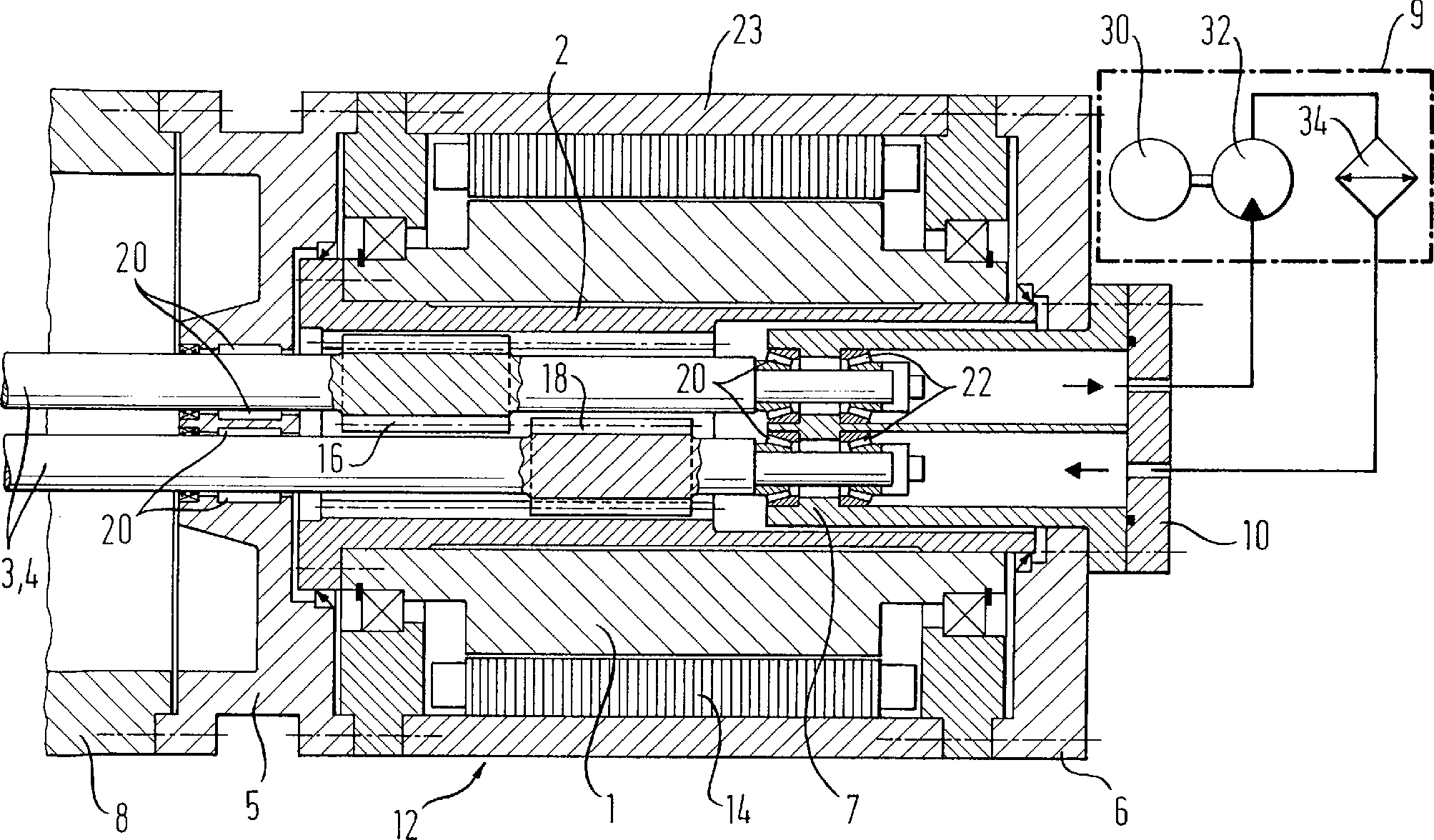
Antriebsvorrichtung für einen gleichsinnig drehenden Mehrschneckenextruder, mit einem in einem Gehäuse (12) aufgenommenen Antriebsmotor, der einen Stator (14) und einen Rotor (1) aufweist, wobei der Rotor (1) mit den Antriebswellen (3, 4) der Extruderschnecken wirkverbunden ist, dadurch gekennzeichnet, dass an dem Rotor (1) eine Verzahnung angeordnet ist, die mit komplementären Verzahnungen (16, 18) an zumindest zwei der Antriebswellen (3, 4) der Extruderschnecken im direkten Eingriff steht.Drive device for a multi-screw extruder rotating in the same direction, with a drive motor accommodated in a housing (12), which has a stator (14) and a rotor (1), the rotor (1) being operatively connected to the drive shafts (3, 4) of the extruder screws , characterized in that a toothing is arranged on the rotor (1) which is in direct engagement with complementary toothing (16, 18) on at least two of the drive shafts (3, 4) of the extruder screws.
Description
Die Erfindung betrifft eine Antriebsvorrichtung für einen gleichsinnig drehenden Mehrwellenextruder gemäß dem Oberbegriff des Anspruchs 1.The invention relates to a drive device for one Multi-shaft extruder rotating in the same direction according to the preamble of the claim 1.
Ein gleichsinnig drehender Mehrschneckenextruder weißt herkömmlicher Weise einen Antriebsmotor, ein Untersetzungsgetriebe und ein Verteilergetriebe auf, welches die Kraft von dem Antriebsmotor auf die Extruderschnecken überträgt.A co-rotating multi-screw extruder know conventional Way a drive motor, a reduction gear and a transfer case which transfers the power from the drive motor to the extruder screws.
Diese konstruktive Ausgestaltung benötigt jedoch einen viel zu großen Platz, verursacht eine sperrige Bauweise und zudem zu hohe Kosten.This constructive design needed however a much too big one Space, causes a bulky construction and also too high costs.
Aus der
Aufgabe der vorliegenden Erfindung ist es, eine einfache und platzsparende Konstruktion für einen gleichsinnig drehenden Mehrschneckenextruder anzugeben.Object of the present invention is a simple and space saving construction for one Specify co-rotating multi-screw extruder.
Diese Aufgabe wird durch eine Antriebsvorrichtung mit den im Anspruch 1 angegebenen Merkmale gelöst.This task is accomplished by a drive device solved with the features specified in claim 1.
Demgemäß wird bei einer Antriebsvorrichtung für einen gleichsinnig drehenden Mehrschneckenextruder gemäß der eingangs genannten Art ein Rotor mit einer Verzahnung vorgesehen, die mit komplimentären Verzahnungen an zumindest zwei der Antriebswellen der Extruderschnecken im direkten Eingriff steht. Wird die Antriebsvorrichtung am Extrudergehäuse angeordnet, dann kämmt also die am Rotor angeordnete Verzahnung direkt mit den an den Antriebswellen vorgesehenen Verzahnungen. Durch diese konstruktive Ausgestaltung wird ein integriertes Verteilergetriebe geschaffen, welches bereits signifikant zu einer Platzeinsparung sowie einer Vereinfachung der Gesamtkonstruktion beiträgt.Accordingly, in a driving device for one co-rotating multi-screw extruder according to the type mentioned a rotor with teeth provided with complementary teeth on at least two of the drive shafts of the extruder screws in direct engagement stands. If the drive device is arranged on the extruder housing, then combs that is, the teeth arranged on the rotor directly with those on the drive shafts provided gears. Through this constructive design an integrated transfer case is created, which already significantly to a space saving and a simplification of the Overall construction contributes.
Gemäß einer besonders bevorzugten Ausführungsform wird als Antriebsmotor ein Hohlwellenmotor vorgesehen, in dessen Hohlraum radial innerhalb des Rotors die Antriebswellen platzsparend aufgenommen werden können. Dies erlaubt nochmals eine kompaktere Bauweise der Antriebsvorrichtung sowie die Verwendung eines Motors mit hohem Drehmoment, der die erforderliche Extrudierleistung in guter Weise erbringen kann.According to a particularly preferred embodiment a hollow shaft motor is provided as the drive motor, in the Cavity radially inside the rotor saves space on the drive shafts can be included. This again allows a more compact design of the drive device and the use of a high torque motor that does the required Can perform extrusion performance in a good manner.
Insbesondere bei einer Verwendung eines Hohlwellenmotors mit einem innenliegenden Rotor, kann dieser mit einer Innenverzahnung versehen werden sein, die mit der komplimentären Verzahnung auf den Antriebswellen der Extruderschnecken bei montierter Antriebsvorrichtung in Eingriff steht. Die Verzahnung auf den Antriebswellen der Extruderschnecken können in Form von Zahnkränzen mit Außenverzahnung ausgebildet sein.Especially when used a hollow shaft motor with an internal rotor, this can be provided with an internal toothing, which with the complementary toothing the drive shafts of the extruder screws with the drive device installed is engaged. The teeth on the drive shafts of the extruder screws can in the form of sprockets with external teeth be trained.
Um sicherzustellen, dass sich die Zahnkränze von verschiedenen Antriebswellen, auch bei dicht kämmenden Extruderschnecken nicht behindern, können diese axial gegeneinander versetzt angeordnet sein.To make sure that the Cassettes of different drive shafts, even with closely meshing ones Not hinder extruder screws, they can axially against each other be staggered.
Gemäß einer bevorzugten Ausführungsform ist die Innenverzahnung selbst nicht unmittelbar am Rotor selbst ausgebildet, sondern an einer Büchse, die wiederum fest mit dem Rotor verbunden ist.According to a preferred embodiment the internal toothing itself is not formed directly on the rotor itself, but on a box that is in turn firmly connected to the rotor.
Gemäß einer weiteren bevorzugten Ausführungsform ist die Antriebsvorrichtung über einen Verbindungsflansch oder eine Verbindungseinrichtung an ein Extrudergehäuse anbringbar. In dem als Flansch ausgebildeten Verbindungselement kann in bevorzugter Weise eine radiale Lagerung der Antriebswellen der Extruderschnecken erfolgen. Eine radiale, sowie eine axiale Lagerung der Extruderschnecken kann darüber hinaus auf der dem Extrudergehäuse gegenüberliegenden Seite der Antriebsvorrichtung mittels eines Enddeckels erfolgen. Dieser Enddeckel kann ein- oder mehrteilig aufgebaut sein.According to another preferred embodiment the drive device is over a connecting flange or a connecting device extruder barrel mountable. In the connecting element designed as a flange can preferably a radial mounting of the drive shafts the extruder screws. A radial as well as an axial Storage of the extruder screws can also be on the opposite of the extruder housing Side of the drive device by means of an end cover. This end cover can be constructed in one or more parts.
Über den Enddeckel – also Kopfseitig der gesamten aufzubauenden Extruderanordnung – kann ferner eine Kühlung und Schmierung des Verteilergetriebes erfolgen. Dazu kann an den Enddeckel ein externes Kühlaggregat angeschlossen werden. Der Enddeckel selbst ist dabei mit entsprechenden Kanälen ausgestattet, die einen Kühlmittelfluss in das Verteilergetriebe hinein sowie aus dem Verteilergetriebe heraus ermöglichen.about the end cover - well Headside of the entire extruder assembly to be built - can also a cooling and lubrication of the transfer case. You can do this at the End cover an external cooling unit be connected. The end cover itself is with appropriate channels equipped with a coolant flow into the transfer case and out of the transfer case enable.
Vorzugsweise wird die vorliegende Erfindung bei einem gleichsinnig drehenden Doppelwellenextruder eingesetzt, wobei als Antriebsmotor ein regelbarer, elektrischer Antrieb verwendet wird.Preferably the present one Invention in a co-rotating twin-screw extruder used, with a controllable, electric as the drive motor Drive is used.
Nachfolgend wird die vorliegende Erfindung anhand der einzigen beigefügten Zeichnung näher erläutert. Die Zeichnung zeigt einen schematische Aufbau einer erfindungsgemäßen Antriebsvorrichtung, die an ein Extrudergehäuse angeflanscht ist.Below is the present Invention explained with reference to the single accompanying drawing. The Drawing shows a schematic structure of a drive device according to the invention, to an extruder housing is flanged.
Das vorliegende Ausführungsbeispiel ist auf einen gleichsinnig drehenden Doppelwellenextruder gerichtet. Jedoch ist dies nicht einschränkend zu verstehen. Die Erfindung kann in gleicher Weise mit gleichsinnig drehenden Mehrschneckenextrudern verwirklicht werden.The present embodiment is aimed at a co-rotating twin-screw extruder. However, this is not restrictive to understand. The invention can in the same way with the same direction rotating multi-screw extruders.
Vorliegend umfasst die erfindungsgemäße Antriebsvorrichtung
ein Gehäuse
Radial innerhalb des Kühlmantels
Das Gehäuse
Jede Antriebswelle
Am – in der Figur – hinteren
Ende der Antriebsvorrichtung ist vorliegend eine dreiteilige Deckeleinheit
mit einem Enddeckel
In dem kombinierten Element aus Einsatz
Insgesamt die sind die Antriebswellen
Der Enddeckel
Beim Betrieb des vorzugsweise regelbaren Antriebsmotors
setzt der Rotor
Überdies ist eine besonders einfache Montage bzw. Demontage der Antriebsvorrichtung möglich. Es muss lediglich die nicht näher dargestellte und beschriebene Befestigung der Antriebsvorrichtung gegenüber dem Extrudergehäuse gelöst werden. Sodann kann die Antriebsvorrichtung einfach abgezogen bzw. im umgekehrten Fall also bei der Montage aufgesteckt werden.moreover is a particularly simple assembly and disassembly of the drive device possible. It only does not need the closer shown and described attachment of the drive device across from the extruder housing solved become. The drive device can then simply be pulled off or in the opposite case, they can be attached during assembly.
Ein separates Verteilergetriebe sowie ein separates Untersetzungsgetriebe ist jedenfalls nicht mehr notwendig.A separate transfer case as well in any case, a separate reduction gear is no longer necessary.
- 11
- Rotorrotor
- 22
- Innenverzahnte Büchseinternal Gear rifle
- 33
- Erste AntriebswelleFirst drive shaft
- 44
- Zweite AntriebswelleSecond drive shaft
- 55
- Verbindungsflanschconnecting flange
- 66
- EnddeckelEnd covers
- 77
- Einsatzcommitment
- 88th
- Extrudergehäuseextruder barrel
- 99
- Externes Kühlaggregatexternal cooling unit
- 1010
- Deckelkopfcover head
- 1212
- Gehäusecasing
- 1414
- Statorstator
- 1616
- Zahnkranz auf erster Antriebswellesprocket on the first drive shaft
- 1818
- Zahnkranz auf zweiter Antriebswellesprocket on the second drive shaft
- 2020
- Radial- und AxiallagerRadial- and thrust bearing
- 2222
- Radiallagerradial bearings
- 2323
- Kühlmantelcooling jacket
- 3030
- Motorengine
- 3232
- Pumpepump
- 3434
- Kühlercooler
Claims (12)
Priority Applications (6)
| Application Number | Priority Date | Filing Date | Title |
|---|---|---|---|
| DE10220552A DE10220552B4 (en) | 2002-05-08 | 2002-05-08 | Drive device for a multi-shaft extruder rotating in the same direction |
| DE50308917T DE50308917D1 (en) | 2002-05-08 | 2003-04-26 | DRIVE DEVICE FOR A MULTI-WHEEL TWIN-WAVE EXTRUDOR |
| AU2003233079A AU2003233079A1 (en) | 2002-05-08 | 2003-04-26 | Drive device for a multi-shaft extruder rotating in the same direction |
| PCT/EP2003/004388 WO2003095178A1 (en) | 2002-05-08 | 2003-04-26 | Drive device for a multi-shaft extruder rotating in the same direction |
| EP03727380A EP1506081B1 (en) | 2002-05-08 | 2003-04-26 | Drive device for a multi-shaft extruder rotating in the same direction |
| US10/980,642 US7182504B2 (en) | 2002-05-08 | 2004-11-03 | Drive apparatus for a multi-shaft extruder rotating in a same direction |
Applications Claiming Priority (1)
| Application Number | Priority Date | Filing Date | Title |
|---|---|---|---|
| DE10220552A DE10220552B4 (en) | 2002-05-08 | 2002-05-08 | Drive device for a multi-shaft extruder rotating in the same direction |
Publications (2)
| Publication Number | Publication Date |
|---|---|
| DE10220552A1 DE10220552A1 (en) | 2003-11-27 |
| DE10220552B4 true DE10220552B4 (en) | 2004-07-15 |
Family
ID=29285210
Family Applications (2)
| Application Number | Title | Priority Date | Filing Date |
|---|---|---|---|
| DE10220552A Expired - Fee Related DE10220552B4 (en) | 2002-05-08 | 2002-05-08 | Drive device for a multi-shaft extruder rotating in the same direction |
| DE50308917T Expired - Lifetime DE50308917D1 (en) | 2002-05-08 | 2003-04-26 | DRIVE DEVICE FOR A MULTI-WHEEL TWIN-WAVE EXTRUDOR |
Family Applications After (1)
| Application Number | Title | Priority Date | Filing Date |
|---|---|---|---|
| DE50308917T Expired - Lifetime DE50308917D1 (en) | 2002-05-08 | 2003-04-26 | DRIVE DEVICE FOR A MULTI-WHEEL TWIN-WAVE EXTRUDOR |
Country Status (5)
| Country | Link |
|---|---|
| US (1) | US7182504B2 (en) |
| EP (1) | EP1506081B1 (en) |
| AU (1) | AU2003233079A1 (en) |
| DE (2) | DE10220552B4 (en) |
| WO (1) | WO2003095178A1 (en) |
Families Citing this family (12)
| Publication number | Priority date | Publication date | Assignee | Title |
|---|---|---|---|---|
| EP1454733A1 (en) * | 2003-02-01 | 2004-09-08 | Reifenhäuser GmbH & Co. Maschinenfabrik | Extrusion apparatus |
| DE10320599B4 (en) * | 2003-05-08 | 2010-04-01 | Siemens Ag | Drive device for plastic extruder with backward removable extruder screw |
| DE102004050450A1 (en) * | 2004-10-16 | 2006-04-20 | Thielenhaus Technologies Gmbh | Geared motor for screw extruder |
| DE102005022739A1 (en) * | 2005-05-13 | 2006-11-16 | Cincinnati Extrusion Gmbh | Drive e.g. for multiple screw extruder, has two screws with first screw connected to drive shaft with electric drive in connection and electric drive has stator and rotor |
| DE102005023032A1 (en) * | 2005-05-13 | 2006-11-23 | Demag Ergotech Gmbh | Electric drive device |
| EP1839840B1 (en) | 2006-03-31 | 2009-12-30 | Coperion GmbH | Drive unit for twin screw machine |
| DE102006024712A1 (en) | 2006-05-26 | 2007-12-06 | Siemens Ag | drive system |
| WO2013183100A1 (en) * | 2012-06-04 | 2013-12-12 | 株式会社栗本鐵工所 | Kneading machine |
| DE102013021902B4 (en) * | 2013-12-26 | 2017-06-14 | HENKE Property UG (haftungsbeschränkt) | Melting pump for building up pressure for pushing plastic melt through a tool |
| KR102396608B1 (en) * | 2016-03-15 | 2022-05-12 | 나이키 이노베이트 씨.브이. | Transmission device for motor-operated tensioning systems for footwear |
| WO2021244772A1 (en) | 2020-06-04 | 2021-12-09 | Sew-Eurodrive Gmbh & Co. Kg | Drive and method for operating a drive |
| CN118855933B (en) * | 2024-09-26 | 2024-12-03 | 常州润渤传动设备有限公司 | Gear box for five-screw extruder |
Citations (1)
| Publication number | Priority date | Publication date | Assignee | Title |
|---|---|---|---|---|
| DE20022605U1 (en) * | 2000-08-09 | 2001-11-29 | Reifenhäuser GmbH & Co. Maschinenfabrik, 53844 Troisdorf | Extrusion device |
Family Cites Families (10)
| Publication number | Priority date | Publication date | Assignee | Title |
|---|---|---|---|---|
| DE846012C (en) * | 1944-04-01 | 1952-08-07 | Dynamit Nobel Ag | Device for producing press mixtures from hardenable plastic masses |
| FR915763A (en) * | 1945-10-12 | 1946-11-18 | Intermediate transmission device by internal toothed gears | |
| US3359826A (en) * | 1965-11-24 | 1967-12-26 | Anger Plastic Gmbh | Driving gearing for plastic extruders |
| DE2619019C3 (en) * | 1976-04-30 | 1979-10-11 | Esde Maschinentechnik Gmbh, 4970 Bad Oeynhausen | Extruder gearbox with two output shafts arranged parallel to the axis |
| DE2801138C3 (en) * | 1978-01-12 | 1981-06-19 | Leistritz Maschinenfabrik Paul Leistritz GmbH, 8500 Nürnberg | Transfer case, especially for twin screw presses |
| DE3237257C2 (en) * | 1982-10-08 | 1985-09-26 | Battenfeld Extrusionstechnik GmbH, 4970 Bad Oeynhausen | Gear for twin screw extruder |
| DE3940833C1 (en) * | 1989-12-11 | 1990-09-27 | Rhodia Ag, 7800 Freiburg, De | |
| DE29805025U1 (en) * | 1998-03-19 | 1999-07-29 | Siemens AG, 80333 München | Production machine with electrical drives for use in the plastics industry |
| DE50002271D1 (en) * | 2000-08-09 | 2003-06-26 | Reifenhaeuser Masch | extruding |
| DE10132002C5 (en) * | 2001-07-03 | 2009-12-31 | Windmöller & Hölscher Kg | Direct drive extruder |
-
2002
- 2002-05-08 DE DE10220552A patent/DE10220552B4/en not_active Expired - Fee Related
-
2003
- 2003-04-26 AU AU2003233079A patent/AU2003233079A1/en not_active Abandoned
- 2003-04-26 EP EP03727380A patent/EP1506081B1/en not_active Expired - Lifetime
- 2003-04-26 DE DE50308917T patent/DE50308917D1/en not_active Expired - Lifetime
- 2003-04-26 WO PCT/EP2003/004388 patent/WO2003095178A1/en not_active Ceased
-
2004
- 2004-11-03 US US10/980,642 patent/US7182504B2/en not_active Expired - Fee Related
Patent Citations (1)
| Publication number | Priority date | Publication date | Assignee | Title |
|---|---|---|---|---|
| DE20022605U1 (en) * | 2000-08-09 | 2001-11-29 | Reifenhäuser GmbH & Co. Maschinenfabrik, 53844 Troisdorf | Extrusion device |
Also Published As
| Publication number | Publication date |
|---|---|
| DE10220552A1 (en) | 2003-11-27 |
| DE50308917D1 (en) | 2008-02-14 |
| AU2003233079A1 (en) | 2003-11-11 |
| US20050063245A1 (en) | 2005-03-24 |
| WO2003095178A1 (en) | 2003-11-20 |
| EP1506081A1 (en) | 2005-02-16 |
| US7182504B2 (en) | 2007-02-27 |
| EP1506081B1 (en) | 2008-01-02 |
Similar Documents
| Publication | Publication Date | Title |
|---|---|---|
| DE10220552B4 (en) | Drive device for a multi-shaft extruder rotating in the same direction | |
| DE102009029716B4 (en) | electric motor | |
| DE4322674C2 (en) | Electric gear motor for a vehicle | |
| DE10230876B3 (en) | Drive device for a plastic processing machine | |
| EP0688090B1 (en) | Motor cooling system | |
| DE102010040399A1 (en) | Housing for receiving an electric drive | |
| EP1182027B1 (en) | Drive for extrusion apparatus | |
| EP0749643B1 (en) | Electric motor | |
| DE102020203459A1 (en) | Transmission oil filter module | |
| EP3899281B1 (en) | Drive device for a motor vehicle | |
| WO2024027988A1 (en) | Electric machine | |
| EP2343254B1 (en) | Drum motor | |
| DE102019118958A1 (en) | Electric drive unit for a motor vehicle | |
| EP1536139A1 (en) | Pump unit with a gear pump and an electric motor | |
| WO2021151598A1 (en) | Electric drive device for a vehicle, and vehicle | |
| DE102020201127A1 (en) | Electric drive of an electrically powered vehicle | |
| EP0432349A2 (en) | Transmission | |
| DE102010061202A1 (en) | vacuum pump | |
| DE202006014565U1 (en) | Oil pump driving equipment for use in e.g. automated gear box of motor vehicle, has electric motor arranged outside of pump housing and drive-connected with internal gear by torque proof drive connection | |
| DE102011003249A1 (en) | Gear assembly for rail vehicle, has driving and driven wheels fixed to housing shell along toothing of wheels for increasing lubricant or oil supply from lubricant inlet to lubricant outlet in circumferential direction | |
| EP3358225B1 (en) | Compact transmission motor assembly | |
| DE1939505A1 (en) | Electrically operated hand tools | |
| AT9633U1 (en) | INJECTION MOLDING MACHINE WITH AT LEAST ONE DIRECT DRIVE | |
| WO2019154682A1 (en) | Electric drive unit for a motor vehicle | |
| DE102008013677A1 (en) | Cooling agent pump for cooling circuit of internal combustion engine of motor vehicle, comprises pump housing, which is formed as integral component, and console is provided, which is stored at internal combustion engine |
Legal Events
| Date | Code | Title | Description |
|---|---|---|---|
| OP8 | Request for examination as to paragraph 44 patent law | ||
| 8363 | Opposition against the patent | ||
| 8327 | Change in the person/name/address of the patent owner |
Owner name: KRAUSS MAFFEI GMBH, 80997 MUENCHEN, DE |
|
| 8327 | Change in the person/name/address of the patent owner |
Owner name: KRAUSSMAFFEI TECHNOLOGIES GMBH, 80997 MUENCHEN, DE |
|
| 8365 | Fully valid after opposition proceedings | ||
| 8339 | Ceased/non-payment of the annual fee |