DE102021131663B4 - FLEXIBLE SHELVING UNIT - Google Patents
FLEXIBLE SHELVING UNIT Download PDFInfo
- Publication number
- DE102021131663B4 DE102021131663B4 DE102021131663.4A DE102021131663A DE102021131663B4 DE 102021131663 B4 DE102021131663 B4 DE 102021131663B4 DE 102021131663 A DE102021131663 A DE 102021131663A DE 102021131663 B4 DE102021131663 B4 DE 102021131663B4
- Authority
- DE
- Germany
- Prior art keywords
- vertical guide
- guide frame
- reinforcement section
- lateral reinforcement
- slot
- Prior art date
- Legal status (The legal status is an assumption and is not a legal conclusion. Google has not performed a legal analysis and makes no representation as to the accuracy of the status listed.)
- Active
Links
Images

Classifications
-
- A—HUMAN NECESSITIES
- A47—FURNITURE; DOMESTIC ARTICLES OR APPLIANCES; COFFEE MILLS; SPICE MILLS; SUCTION CLEANERS IN GENERAL
- A47F—SPECIAL FURNITURE, FITTINGS, OR ACCESSORIES FOR SHOPS, STOREHOUSES, BARS, RESTAURANTS OR THE LIKE; PAYING COUNTERS
- A47F5/00—Show stands, hangers, or shelves characterised by their constructional features
- A47F5/10—Adjustable or foldable or dismountable display stands
-
- A—HUMAN NECESSITIES
- A47—FURNITURE; DOMESTIC ARTICLES OR APPLIANCES; COFFEE MILLS; SPICE MILLS; SUCTION CLEANERS IN GENERAL
- A47B—TABLES; DESKS; OFFICE FURNITURE; CABINETS; DRAWERS; GENERAL DETAILS OF FURNITURE
- A47B57/00—Cabinets, racks or shelf units, characterised by features for adjusting shelves or partitions
- A47B57/06—Cabinets, racks or shelf units, characterised by features for adjusting shelves or partitions with means for adjusting the height of the shelves
- A47B57/26—Cabinets, racks or shelf units, characterised by features for adjusting shelves or partitions with means for adjusting the height of the shelves consisting of clamping means, e.g. with sliding bolts or sliding wedges
-
- A—HUMAN NECESSITIES
- A47—FURNITURE; DOMESTIC ARTICLES OR APPLIANCES; COFFEE MILLS; SPICE MILLS; SUCTION CLEANERS IN GENERAL
- A47B—TABLES; DESKS; OFFICE FURNITURE; CABINETS; DRAWERS; GENERAL DETAILS OF FURNITURE
- A47B57/00—Cabinets, racks or shelf units, characterised by features for adjusting shelves or partitions
- A47B57/04—Cabinets, racks or shelf units, characterised by features for adjusting shelves or partitions with means for adjusting the inclination of the shelves
- A47B57/045—Cantilever shelves
-
- A—HUMAN NECESSITIES
- A47—FURNITURE; DOMESTIC ARTICLES OR APPLIANCES; COFFEE MILLS; SPICE MILLS; SUCTION CLEANERS IN GENERAL
- A47B—TABLES; DESKS; OFFICE FURNITURE; CABINETS; DRAWERS; GENERAL DETAILS OF FURNITURE
- A47B57/00—Cabinets, racks or shelf units, characterised by features for adjusting shelves or partitions
- A47B57/06—Cabinets, racks or shelf units, characterised by features for adjusting shelves or partitions with means for adjusting the height of the shelves
- A47B57/08—Cabinets, racks or shelf units, characterised by features for adjusting shelves or partitions with means for adjusting the height of the shelves consisting of grooved or notched ledges, uprights or side walls
- A47B57/10—Cabinets, racks or shelf units, characterised by features for adjusting shelves or partitions with means for adjusting the height of the shelves consisting of grooved or notched ledges, uprights or side walls the grooved or notched parts being the side walls or uprights themselves
-
- A—HUMAN NECESSITIES
- A47—FURNITURE; DOMESTIC ARTICLES OR APPLIANCES; COFFEE MILLS; SPICE MILLS; SUCTION CLEANERS IN GENERAL
- A47B—TABLES; DESKS; OFFICE FURNITURE; CABINETS; DRAWERS; GENERAL DETAILS OF FURNITURE
- A47B57/00—Cabinets, racks or shelf units, characterised by features for adjusting shelves or partitions
- A47B57/06—Cabinets, racks or shelf units, characterised by features for adjusting shelves or partitions with means for adjusting the height of the shelves
- A47B57/20—Cabinets, racks or shelf units, characterised by features for adjusting shelves or partitions with means for adjusting the height of the shelves consisting of tongues, pins or similar projecting means coacting with openings
- A47B57/22—Cabinets, racks or shelf units, characterised by features for adjusting shelves or partitions with means for adjusting the height of the shelves consisting of tongues, pins or similar projecting means coacting with openings characterised by shape or orientation of opening, e.g. keyhole-shaped
-
- A—HUMAN NECESSITIES
- A47—FURNITURE; DOMESTIC ARTICLES OR APPLIANCES; COFFEE MILLS; SPICE MILLS; SUCTION CLEANERS IN GENERAL
- A47B—TABLES; DESKS; OFFICE FURNITURE; CABINETS; DRAWERS; GENERAL DETAILS OF FURNITURE
- A47B57/00—Cabinets, racks or shelf units, characterised by features for adjusting shelves or partitions
- A47B57/06—Cabinets, racks or shelf units, characterised by features for adjusting shelves or partitions with means for adjusting the height of the shelves
- A47B57/26—Cabinets, racks or shelf units, characterised by features for adjusting shelves or partitions with means for adjusting the height of the shelves consisting of clamping means, e.g. with sliding bolts or sliding wedges
- A47B57/265—Cabinets, racks or shelf units, characterised by features for adjusting shelves or partitions with means for adjusting the height of the shelves consisting of clamping means, e.g. with sliding bolts or sliding wedges clamped in discrete positions, e.g. on tubes with grooves or holes
-
- A—HUMAN NECESSITIES
- A47—FURNITURE; DOMESTIC ARTICLES OR APPLIANCES; COFFEE MILLS; SPICE MILLS; SUCTION CLEANERS IN GENERAL
- A47B—TABLES; DESKS; OFFICE FURNITURE; CABINETS; DRAWERS; GENERAL DETAILS OF FURNITURE
- A47B96/00—Details of cabinets, racks or shelf units not covered by a single one of groups A47B43/00 - A47B95/00; General details of furniture
- A47B96/02—Shelves
- A47B96/027—Cantilever shelves
- A47B96/028—Cantilever shelves characterised by support bracket location means, e.g. fixing means between support bracket and shelf
Landscapes
- Assembled Shelves (AREA)
Abstract
Flexible Regaleinheit (10), umfassend:
einen Tragrahmen (12) mit mindestens einem vertikalen Führungsgestell (14, 16), wobei das mindestens eine vertikale Führungsgestell (14, 16) mindestens einen länglichen Schlitz (32, 36) beinhaltet;
eine Regaleinheit (18), die von dem mindestens einen vertikalen Führungsgestell (14, 16) getragen wird, wobei die Regaleinheit (18) eine Regalplatte (20), die von einem vorderen Verstärkungsabschnitt (22) und mindestens einem seitlichen Verstärkungsabschnitt (24, 26) eingerahmt wird, enthält;
wobei die Regaleinheit (18), wenn sie sich in einer Freigabeposition (26a) befindet, in ausgewählte Aufwärts- und Abwärtspositionen durch vertikale Verschiebung mindestens eines Positionierungsstifts (30, 34), der mit dem mindestens einen seitlichen Verstärkungsabschnitt (24, 26) verbunden ist und sich von diesem erstreckt, bewegbar ist, wobei der Positionierungsstift (30, 34) innerhalb des länglichen Schlitzes (32, 36) positioniert ist und gleitet; und
eine flache Endfläche (64) des mindestens einen seitlichen Verstärkungsabschnitts (24, 26) berührt direkt eine Plattenfläche (70) des mindestens einen vertikalen Führungsgestells (14, 16), wobei sich der mindestens eine seitliche Verstärkungsabschnitt (24, 26) und die Regalplatte (20) in einer horizontalen Position (28) befinden, um die Regaleinheit durch Reibung in der horizontalen Position (28) zu halten;
einen U-förmigen Schlitz (50) in dem mindestens einen seitlichen Verstärkungsabschnitt (24, 26) mit einem ersten Schlitzabschnitt (52) und einem zweiten Schlitzabschnitt (54); und
einen in dem U-förmigen Schlitz (50) verschiebbar angeordneten Anschlagstift (58) und eine mit dem Anschlagstift (58) verbundene Sechskantmutter (60), wobei die Sechskantmutter (60) mehrere flache Flächen (74) umfasst;
wobei ein Reibungswiderstand gegen eine Drehung des mindestens einen seitlichen Verstärkungsabschnitts (24, 26) in der horizontalen Position (28) durch eine manuelle Verschiebung des Anschlagstifts (58) aus dem ersten Schlitzabschnitt (52) und in den zweiten Schlitzabschnitt (54) des U-förmigen Schlitzes (50) erhöht wird, wobei eine der mehreren flachen Flächen (74) der Sechskantmutter (60), die mit dem Anschlagstift (58) verbunden ist, eine ebene Fläche (76) des mindestens einen vertikalen Führungsgestells (14, 16) direkt berührt.

a support frame (12) with at least one vertical guide frame (14, 16), wherein the at least one vertical guide frame (14, 16) includes at least one elongated slot (32, 36);
a shelf unit (18) supported by the at least one vertical guide frame (14, 16), the shelf unit (18) including a shelf panel (20) framed by a front reinforcement section (22) and at least one side reinforcement section (24, 26);
wherein the shelf unit (18), when in a release position (26a), is movable into selected upward and downward positions by vertical displacement of at least one positioning pin (30, 34) connected to and extending from the at least one lateral reinforcement portion (24, 26), the positioning pin (30, 34) being positioned and sliding within the elongated slot (32, 36); and
a flat end surface (64) of the at least one lateral reinforcement section (24, 26) directly contacts a plate surface (70) of the at least one vertical guide frame (14, 16), the at least one lateral reinforcement section (24, 26) and the shelf plate (20) being in a horizontal position (28) to frictionally hold the shelf unit in the horizontal position (28);
a U-shaped slot (50) in the at least one lateral reinforcement section (24, 26) having a first slot section (52) and a second slot section (54); and
a stop pin (58) slidably disposed in the U-shaped slot (50) and a hex nut (60) connected to the stop pin (58), the hex nut (60) comprising a plurality of flat surfaces (74);
wherein a frictional resistance to rotation of the at least one lateral reinforcement section (24, 26) in the horizontal position (28) is increased by manually displacing the stop pin (58) from the first slot section (52) and into the second slot section (54) of the U-shaped slot (50), wherein one of the plurality of flat surfaces (74) of the hex nut (60) connected to the stop pin (58) directly contacts a flat surface (76) of the at least one vertical guide frame (14, 16).
Description
Technisches GebietTechnical field
Die vorliegende Offenbarung bezieht sich auf Regale und Merkmale für die flexible Zusammenstellung von Regalen und die Positionierung von Regalböden.The present disclosure relates to shelves and features for flexible assembly of shelves and positioning of shelves.
Einführungintroduction
Der Bedarf an Regalen in einer Werkstatt kann derzeit durch den Kauf handelsüblicher Standardprodukte gedeckt werden. Diese Produkte sind jedoch in der Regel nicht auf spezifische Bedürfnisse zugeschnitten, wie z. B. die Möglichkeit, aus mehreren verschiedenen Regalabständen zu wählen und die Regale bei Nichtgebrauch zu lagern. Herkömmliche Regalbauverfahren zur Herstellung kundenspezifischer Regale erfordern außerdem eine lange Vorlaufzeit und erhöhen die Kosten der Einheiten.The need for shelving in a workshop can currently be met by purchasing off-the-shelf products. However, these products are typically not tailored to specific needs, such as the ability to choose from several different shelf spacings and to store the shelves when not in use. Conventional shelving construction methods for manufacturing custom shelving also require long lead times and increase unit costs.
Die
Die
Die
Die
Die
Die
Während die derzeitigen Regale ihren Zweck erfüllen, ist es Aufgabe der Erfindung, ein neues und verbessertes System und Verfahren zur Bereitstellung flexibler und kostengünstiger Regale bereitzustellen.While current shelving serves its purpose, it is an object of the invention to provide a new and improved system and method for providing flexible and cost-effective shelving.
Gelöst wird diese Aufgabe durch eine flexible Regaleinheit mit den Merkmalen des Anspruchs 1.This task is solved by a flexible shelving unit with the features of claim 1.
Beschreibung der ErfindungDescription of the invention
Gemäß der Erfindung umfasst eine flexible Regaleinheit einen Tragrahmen mit mindestens einem vertikalen Führungsgestell, wobei das mindestens eine vertikale Führungsgestell einen länglichen Schlitz aufweist. Die Regaleinheit wird von dem mindestens einen vertikalen Führungsgestell getragen. Die Regaleinheit umfasst eine Regalplatte, die von einem vorderen Verstärkungsabschnitt und mindestens einem seitlichen Verstärkungsabschnitt eingerahmt ist. Die Regaleinheit wird, wenn sie sich in einer Freigabeposition befindet, durch vertikale Verschiebung mindestens eines Positionierungsstifts, der mit dem mindestens einen seitlichen Verstärkungsabschnitt verbunden ist und sich von diesem erstreckt, der in dem länglichen Schlitz positioniert ist und gleitet, an ausgewählte Stellen nach oben und unten bewegt. Eine flache Endfläche des mindestens einen seitlichen Verstärkungsabschnitts berührt direkt eine Plattenfläche des mindestens einen vertikalen Führungsgestells, wobei sich der mindestens eine seitliche Verstärkungsabschnitt und die Regalplatte in einer horizontalen Position befinden, um die Regaleinheit durch Reibung in der horizontalen Position zu halten. Die flexible Regaleinheit weist ferner einen U-förmigen Schlitz in dem mindestens einen seitlichen Verstärkungsabschnitt mit eine, ersten Schlitzabschnitt und einem zweiten Schlitzabschnitt auf. Ein Anschlagstift ist verschiebbar in dem U-förmigen Schlitz angeordnet und eine Sechskantmutter ist mit dem Anschlagstift verbunden, wobei die Sechskantmutter mehrere flache Flächen aufweist. Ein Reibungswiderstand gegen die Drehung des mindestens einen seitlichen Verstärkungsabschnitts in der horizontalen Position wird durch eine manuelle Verschiebung des Anschlagsstifts aus dem ersten Schlitzabschnitt heraus und in den zweiten Schlitzabschnitt des U-förmigen Schlitzes hinein erhöht, wobei eine der mehreren flachen Flächen der mit dem Anschlagsstift verbundenen Sechskantmutter eine ebene Fläche des mindestens einen vertikalen Führungsgestells direkt berührt.According to the invention, a flexible shelving unit comprises a support frame with at least one vertical guide frame, wherein the at least one vertical guide frame has an elongated slot. The shelving unit is supported by the at least one vertical guide frame. The shelving unit comprises a shelf panel framed by a front reinforcement section and at least one side reinforcement section. The shelving unit, when in a release position, is moved up and down to selected locations by vertical displacement of at least one positioning pin connected to and extending from the at least one side reinforcement section, which is positioned and slides in the elongated slot. A flat end surface of the at least one side reinforcement section directly contacts a panel surface of the at least one vertical guide frame, wherein the at least one side reinforcement section and the shelf panel are in a horizontal position to frictionally hold the shelving unit in the horizontal position. The flexible shelving unit further comprises a U-shaped slot in the at least one side reinforcement section having a first slot portion and a second slot portion. A stop pin is slidably disposed in the U-shaped slot, and a hex nut is connected to the stop pin, the hex nut having a plurality of flat surfaces. Frictional resistance to rotation of the at least one lateral reinforcement portion in the horizontal position is increased by manually displacing the stop pin out of the first slot portion and into the second slot portion of the U-shaped slot, one of the plurality of flat surfaces of the hex nut connected to the stop pin directly contacting a flat surface of the at least one vertical guide frame.
Gemäß einer Ausführungsform definiert das mindestens eine vertikale Führungsgestell ein erstes vertikales Führungsgestell und ein zweites vertikales Führungsgestell, das parallel zum ersten vertikalen Führungsgestell angeordnet ist, wobei die Regaleinheit von und zwischen dem ersten vertikalen Führungsgestell und dem zweiten vertikalen Führungsgestell getragen wird.According to one embodiment, the at least one vertical guide frame defines a first vertical guide frame and a second vertical guide frame arranged parallel to the first vertical guide frame, wherein the shelf unit is supported by and between the first vertical guide frame and the second vertical guide frame.
Gemäß einer weiteren Ausführungsform definiert der mindestens eine seitliche Verstärkungsabschnitt einen ersten seitlichen Verstärkungsabschnitt, der in Bezug auf die erste vertikale Führungsgestell gleitend angeordnet ist, und einen zweiten seitlichen Verstärkungsabschnitt, der in Bezug auf die zweite vertikale Führungsgestell gleitend angeordnet ist.According to a further embodiment, the at least one lateral reinforcement section defines a first lateral reinforcement section slidably arranged with respect to the first vertical guide frame and a second lateral reinforcement section slidably arranged with respect to the second vertical guide frame.
Gemäß einer weiteren Ausführungsform umfasst der mindestens eine Positionierungsstift einen ersten Positionierungsstift, der mit dem ersten seitlichen Verstärkungsabschnitt verbunden ist und sich von diesem erstreckt und verschiebbar in dem länglichen Schlitz der ersten vertikalen Führungszahnstange angeordnet ist, und einen zweiten Positionierungsstift, der mit dem zweiten seitlichen Verstärkungsabschnitt verbunden ist und sich von diesem erstreckt und verschiebbar in dem länglichen Schlitz des zweiten vertikalen Führungsgestells angeordnet ist.According to a further embodiment, the at least one positioning pin comprises a first positioning pin connected to and extending from the first lateral reinforcement portion and slidably mounted in the elongated slot of the first vertical guide rack, and a second positioning pin connected to and extending from the second lateral reinforcement portion and slidably disposed in the elongated slot of the second vertical guide frame.
Gemäß einer weiteren Ausführungsform umfasst der mindestens eine seitliche Verstärkungsabschnitt einen ersten seitlichen Verstärkungsabschnitt, der winklig zum vorderen Verstärkungsabschnitt ausgerichtet ist, und einen zweiten seitlichen Verstärkungsabschnitt, der winklig zum vorderen Verstärkungsabschnitt ausgerichtet ist.According to a further embodiment, the at least one lateral reinforcement section comprises a first lateral reinforcement section which is angularly aligned with the front reinforcement section and a second lateral reinforcement section which is angularly aligned with the front reinforcement section.
Gemäß einer weiteren Ausführungsform weist mindestens eine der flachen Endflächen des mindestens einen seitlichen Verstärkungsabschnitts und die Plattenfläche des mindestens einen vertikalen Führungsgestells eine Textur auf, um den Reibungskontakt zu verbessern, wobei die Textur mindestens eine der folgenden Eigenschaften aufweist: Abtragung, Vertiefung, Oberflächenaufrauung, Rautenmuster und Kreuzschraffur.According to a further embodiment, at least one of the flat end surfaces of the at least one lateral reinforcing section and the plate surface of the at least one vertical guide frame has a texture to improve the frictional contact, wherein the texture has at least one of the following characteristics: abrasion, depression, surface roughening, diamond pattern and cross-hatching.
Gemäß einer weiteren Ausführungsform geht eine abgerundete Ecke des mindestens einen seitlichen Verstärkungsabschnitts in die flache Endfläche über, wobei die abgerundete Ecke es dem mindestens einen seitlichen Verstärkungsabschnitt ermöglicht, sich nach oben zu drehen, um den mindestens einen seitlichen Verstärkungsabschnitt aus der horizontalen Position zu lösen.According to a further embodiment, a rounded corner of the at least one lateral reinforcement section merges into the flat end surface, wherein the rounded corner allows the at least one lateral reinforcement section to rotate upwards in order to release the at least one lateral reinforcement section from the horizontal position.
Gemäß einer weiteren Ausführungsform umfassen der erste längliche Schlitz und der zweite längliche Schlitz jeweils mehrere winklig ausgerichtete Schlitze, die sich in einem Winkel beta von etwa 15 Grad bis zu etwa 75 Grad in einer Abwärtsrichtung in Bezug auf eine horizontale Ebene erstrecken.According to another embodiment, the first elongated slot and the second elongated slot each comprise a plurality of angularly aligned slots extending at an angle beta of about 15 degrees to about 75 degrees in a downward direction with respect to a horizontal plane.
Gemäß einer weiteren Ausführungsform treten der erste Positionierungsstift, der mit dem ersten seitlichen Verstärkungsabschnitt verbunden ist, und der zweite Positionierungsstift, der mit dem zweiten seitlichen Verstärkungsabschnitt verbunden ist, in die winklig ausgerichteten Schlitze ein, wenn sich die Regaleinheit in der horizontalen Position befindet.According to a further embodiment, the first positioning pin connected to the first lateral reinforcement portion and the second positioning pin connected to the second lateral reinforcement portion enter the angularly aligned slots when the shelf unit is in the horizontal position.
Gemäß einer weiteren Ausführungsform ist ein Regalstauschlitz in einem Winkel gamma im Bereich von etwa 15 Grad bis zu etwa 75 Grad in einer Abwärtsrichtung in Bezug auf eine horizontale Ebene nach unten gerichtet, wobei der Regalstauschlitz in Bezug auf die winklig ausgerichteten Schlitze um eine Längsachse des ersten länglichen Schlitzes und des zweiten länglichen Schlitzes entgegengesetzt gerichtet ist.According to a further embodiment, a shelf storage slot is directed downwardly at an angle gamma in the range of about 15 degrees to about 75 degrees in a downward direction with respect to a horizontal plane, the shelf storage slot being oppositely directed with respect to the angularly oriented slots about a longitudinal axis of the first elongate slot and the second elongate slot.
Gemäß einer weiteren Ausführungsform öffnen sich eine Regalablagekerbe und eine Verstärkungsaufnahmekerbe von einer ebenen Fläche des ersten vertikalen Führungsgestells und des zweiten vertikalen Führungsgestells und sind gemeinsam mit dem Regalstauschlitz ausgerichtet.According to another embodiment, a shelf storage notch and a reinforcement receiving notch open from a flat surface of the first vertical guide frame and the second vertical guide frame and are aligned together with the shelf storage slot.
Gemäß einer weiteren Ausführungsform wird die Regaleinheit nach unten in eine Stauposition gedreht, in der eine Ecke des ersten seitlichen Verstärkungsabschnitts und des zweiten seitlichen Verstärkungsabschnitts in die Regalablagekerbe und die Verstärkungsaufnahmekerbe des ersten vertikalen Führungsgestells und des zweiten vertikalen Führungsgestells eintreten kann, wenn der mit dem ersten seitlichen Verstärkungsabschnitt verbundene erste Fixierstift und der mit dem zweiten seitlichen Verstärkungsabschnitt verbundene zweite Fixierstift in die Regalablagekerbe und die Verstärkungsaufnahmekerbe des ersten vertikalen Führungsgestells und des zweiten vertikalen Führungsgestells eintreten.According to a further embodiment, the shelf unit is rotated downward to a storage position in which a corner of the first lateral reinforcement portion and the second lateral reinforcement portion can enter the shelf storage notch and the reinforcement receiving notch of the first vertical guide frame and the second vertical guide frame when the first fixing pin connected to the first lateral reinforcement portion and the second fixing pin connected to the second lateral reinforcement portion enter the shelf storage notch and the reinforcement receiving notch of the first vertical guide frame and the second vertical guide frame.
Gemäß einer weiteren Ausführungsform berührt eine erste flache Endfläche des ersten seitlichen Verstärkungsabschnitts mit einer ersten Lasche, die sich von der ersten flachen Endfläche nach außen erstreckt, eine Plattenfläche des ersten vertikalen Führungsgestells direkt, und eine zweite flache Endfläche des zweiten seitlichen Verstärkungsabschnitts mit einer zweiten Lasche, die sich von der zweiten flachen Endfläche nach außen erstreckt, berührt eine Plattenfläche des zweiten vertikalen Führungsgestells direkt, wobei die erste Lasche in einem von mehreren aufeinanderfolgend beabstandeten Schlitzen aufgenommen ist, die sich durch die Plattenfläche des ersten vertikalen Führungsgestells erstrecken, und wobei die zweite Lasche in einem von mehreren aufeinanderfolgend beabstandeten Schlitzen aufgenommen ist, die sich durch die Plattenfläche des zweiten vertikalen Führungsgestells erstrecken.According to a further embodiment, a first flat end surface of the first lateral reinforcement portion having a first tab extending outwardly from the first flat end surface directly contacts a plate surface of the first vertical guide frame, and a second flat end surface of the second lateral reinforcement portion having a second tab extending outwardly from the second flat end surface directly contacts a plate surface of the second vertical guide frame, wherein the first tab is received in one of a plurality of successively spaced slots extending through the plate surface of the first vertical guide frame, and wherein the second tab is received in one of a plurality of successively spaced slots extending through the plate surface of the second vertical guide frame.
Gemäß einem Aspekt der Offenbarung umfasst ein Verfahren zur Herstellung einer Regaleinheit: Auswählen von Plattenmaterialien und Verstärkungselementen zur Herstellung von Regalkomponenten; Schneiden der Verstärkungselemente und der Plattenmaterialien in vorgefertigte Formen zur Bildung mehrerer Führungsregale, eines Regalhauptkörpers und einer Regaloberfläche; Biegen des Verstärkungselements in eine Regalhauptkörperform; und Zusammenbauen der Regaleinheit.According to one aspect of the disclosure, a method for manufacturing a shelving unit comprises: selecting plate materials and reinforcement members for manufacturing shelving components; cutting the reinforcement members and the plate materials into prefabricated shapes to form a plurality of guide shelves, a shelf main body, and a shelf surface; bending the reinforcement member into a shelf main body shape; and assembling the shelving unit.
Gemäß einer Ausführungsform des Verfahrens umfasst das Verfahren ferner: das Ausbilden eines gekrümmten Merkmals und einer flachen Kontaktfläche, die das Verstärkungselement definieren, das an einem Ende des Regalhauptkörpers positioniert werden soll; das Erzeugen von verlängerten Laschen an einem Ende des Verstärkungselements; und das Hinzufügen von Schlitzen zu den Regalseitenwänden und einer Rückwand zur Aufnahme der verlängerten Laschen.According to one embodiment of the method, the method further comprises: forming a curved feature and a flat contact surface defining the reinforcing element to be positioned at one end of the shelf main body; creating elongated Tabs at one end of the reinforcement member; and adding slots to the shelf side walls and a back wall to accommodate the extended tabs.
Gemäß einer weiteren Ausführungsform des Verfahrens umfasst das Verfahren ferner das Hinzufügen einer Textur zu vorbestimmten Kontaktflächen zwischen den Verstärkungselementen und den Führungsgestellen.According to a further embodiment of the method, the method further comprises adding a texture to predetermined contact surfaces between the reinforcing elements and the guide frames.
Weitere Anwendungsbereiche werden sich aus der vorliegenden Beschreibung ergeben. Es sollte verstanden werden, dass die Beschreibung und die spezifischen Beispiele nur zur Veranschaulichung dienen und den Umfang der vorliegenden Offenbarung nicht einschränken sollen.Further areas of applicability will become apparent from the present description. It should be understood that the description and specific examples are intended for purposes of illustration only and are not intended to limit the scope of the present disclosure.
Kurzbeschreibung der ZeichnungenBrief description of the drawings
Die hier beschriebenen Figuren dienen nur der Veranschaulichung und sollen den Umfang der vorliegenden Offenbarung in keiner Weise einschränken.
-
1 ist eine perspektivische Ansicht der linken Seite einer flexiblen Regaleinheit gemäß einem beispielhaften Aspekt; -
2 ist eine perspektivische Ansicht der linken Seite der flexiblen Regaleinheit von1 in einer Konfiguration mit verstautem Regal; -
3 ist eine Seitenansicht eines Dreh- und Verriegelungssystems für ein flexibles Regal gemäß einem beispielhaften Aspekt; -
4 ist eine Seitenansicht, die eine axiale Drehung der flexiblen Regaleinheit von3 zeigt; -
5 ist eine Seitenansicht eines anderen Dreh- und Verriegelungssystems für ein flexibles Regal gemäß einem beispielhaften Aspekt; -
6 ist eine Seitenansicht, die eine axiale Drehung der flexiblen Regaleinheit von5 zeigt; -
7 ist eine Seitenansicht eines vertikalen Führungsgestells in einem weiteren beispielhaften Aspekt; -
8 ist eine Seitenansicht eines Systems zur Drehung und Verriegelung von Regalen unter Verwendung des vertikalen Führungsgestells von7 ; -
9 ist eine Seitenansicht eines vertikalen Führungsgestells eines weiteren beispielhaften Aspekts;. -
10 ist eine Seitenansicht eines Systems zum Drehen und Verstauen von Regalen unter Verwendung des vertikalen Führungsgestells von9 ; und -
11 ist ein Flussdiagramm der Verfahrensschritte für den Zusammenbau eines flexiblen Regals der vorliegenden Offenbarung.
-
1 is a perspective view of the left side of a flexible shelving unit according to an example aspect; -
2 is a perspective view of the left side of the flexible shelving unit from1 in a configuration with the shelf stowed away; -
3 is a side view of a rotating and locking system for a flexible shelving unit according to an example aspect; -
4 is a side view showing axial rotation of the flexible shelving unit from3 shows; -
5 is a side view of another rotating and locking system for a flexible shelving unit according to an example aspect; -
6 is a side view showing axial rotation of the flexible shelving unit from5 shows; -
7 is a side view of a vertical guide frame in another exemplary aspect; -
8 is a side view of a system for rotating and locking shelves using the vertical guide frame of7 ; -
9 is a side view of a vertical guide frame of another exemplary aspect;. -
10 is a side view of a system for rotating and storing shelves using the vertical guide frame of9 ; and -
11 is a flowchart of the method steps for assembling a flexible shelf of the present disclosure.
Detaillierte BeschreibungDetailed description
Die folgende Beschreibung ist lediglich beispielhaft und soll die vorliegende Offenbarung, Anwendung oder Verwendung nicht einschränken.The following description is merely exemplary and is not intended to limit the present disclosure, application, or uses.
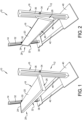
Wie in
Gemäß mehreren Aspekten können Verstärkungselemente und Verstärkungsabschnitte der vorliegenden Offenbarung, wie z. B. der vordere Verstärkungsabschnitt 22, der erste seitliche Verstärkungsabschnitt 24 und der zweite seitliche Verstärkungsabschnitt 26, mit einer beliebigen von mehreren geometrischen Formen ausgebildet werden, um die strukturelle Steifigkeit zu verbessern. Diese geometrischen Formen können rund, halbrund, I-Träger-förmig, L-förmig, rechteckig, Kombinationen der oben genannten Formen und dergleichen sein. Eine hintere Ecke der Regaleinheit 18 kann auch ein Verstärkungselement enthalten, das unterhalb der Regalplatte 20 angeordnet ist und sich über die Breite der Regaleinheit 18 ähnlich wie der vordere Verstärkungsabschnitt 22 erstreckt.According to several aspects, reinforcement members and reinforcement sections of the present disclosure, such as the
Der Tragrahmen 12 kann ferner eine erste Grundplatte 38, die an einem unteren Ende des ersten vertikalen Führungsgestells 14 befestigt ist, und eine zweite Grundplatte 40, die an einem unteren Ende des zweiten vertikalen Führungsgestellt 16 befestigt ist, umfassen, die der flexiblen Regaleinheit 10 Stabilität verleihen. Ein erster Versteifungsbügel 42 und ein zweiter Versteifungsbügel 44 können an der ersten Grundplatte 38 und an der zweiten Grundplatte 40 befestigt werden, um zu verhindern, dass sich das erste vertikale Führungsgestell 14 von dem zweiten vertikalen Führungsgestell 16 wegbewegt.The
Unter Bezugnahme auf
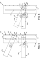
Unter Bezugnahme auf
Die Regaleinheit 18 umfasst einen u-förmigen Schlitz 50 in jedem der seitlichen Verstärkungsabschnitte, wobei aus Gründen der Übersichtlichkeit nur der zweite seitliche Verstärkungsabschnitt 26 dargestellt ist, der einen nach unten gerichteten ersten Schlitzabschnitt 52 umfasst, der über einen Verbindungsschlitzabschnitt 53 mit einem nach unten gerichteten zweiten Schlitzabschnitt 54 verbunden ist, der parallel zum ersten Schlitzabschnitt 52 verläuft. Eine Hilfsstopperbaugruppe 57 ist in einzelnen der U-förmigen Schlitze 50 verschiebbar angeordnet. Die Hilfsstopperbaugruppen 57 umfassen jeweils einen Anschlagsstift 58, der in dem U-förmigen Schlitz 50 verschiebbar angeordnet ist, und eine Sechskantmutter 60, die mit dem Anschlagsstift 58 verbunden ist. Wenn die Regaleinheit 18 für eine Aufwärts- und Abwärtsgleitbewegung freigegeben wird, wie im oberen Teil von
Der zweite seitliche Verstärkungsabschnitt 26 umfasst außerdem eine abgerundete Ecke 62, die in eine flache Endfläche 64 übergeht. Die abgerundete Ecke 62 bietet Spielraum für die Drehung des zweiten seitlichen Verstärkungsabschnitts 26. Durch Drehen des zweiten seitlichen Verstärkungsabschnitts 26 in Bezug auf den zweiten Positionierungsstift 34 wird eine Bodenfläche 66 des zweiten seitlichen Verstärkungsabschnitts 26 von der Freigabeposition 26a, die unter dem Winkel α ausgerichtet ist, in eine horizontale, feststehende Position der Regaleinheit überführt, in der die Bodenfläche 66 mit einer horizontalen Ebene 68 ausgerichtet ist.The second
In der festen Position der Regaleinheit, in der der zweite seitliche Verstärkungsabschnitt 26 horizontal ausgerichtet ist, berührt die flache Endfläche 64 direkt eine Plattenfläche 70 des zweiten vertikalen Führungsgestells 16, die danach einen Reibungswiderstand gegen eine weitere Verschiebung des zweiten seitlichen Verstärkungsabschnitts 26 nach oben oder unten bietet und der Schwerkraft 72 widersteht, die den zweiten seitlichen Verstärkungsabschnitt 26 unter Last nach unten zieht. Dieser Reibungswiderstand wird durch manuelles Verschieben des Anschlagstifts 58 aus dem ersten Schlitzabschnitt 52 und durch den Verbindungsschlitzabschnitt 53 in den zweiten Schlitzabschnitt 54 des U-förmigen Schlitzes 50 verstärkt. Wenn der Anschlagstift 58 im zweiten Schlitzabschnitt 54 positioniert ist, berührt eine von mehreren flachen Flächen 74 der mit dem Anschlagstift 58 verbundenen Sechskantmutter 60 direkt eine ebene Fläche 76 der zweiten vertikalen Führungsgestell 16, die parallel zur Plattenfläche 70 ausgerichtet ist. Dieser direkte Kontakt bietet einen weiteren Widerstand gegen die Drehung des zweiten vertikalen Führungsgestells 16 in Bezug auf den zweiten Positionierungsstift 34.In the fixed position of the shelving unit, with the second
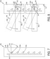
Unter Bezugnahme auf
Unter Bezugnahme auf
Unter Bezugnahme auf
Unter Bezugnahme auf
Unter Bezugnahme auf
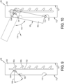
Unter Bezugnahme auf
Unter Bezugnahme auf
Unter weiterer Bezugnahme auf die
Bezug nehmend auf
Das flexible Regal besteht aus Führungsgestellen, Fachböden, Stiften und Anschlägen. Die Fachböden haben Endformen, die aus einer Kurve bestehen, um eine Drehung und ein leichtes Lösen und Einstellen in der Position zu ermöglichen, und eine flache Oberfläche für den Kontakt mit der Regalrückwand und die Selbstverriegelung durch eine Reibungskraft.The flexible shelving system consists of guide rails, shelves, pins, and stops. The shelves have curved end shapes to allow for rotation and easy release and adjustment of position, and a flat surface for contact with the shelf back panel and self-locking through friction.
Die Führungsschienen dienen dazu, dass die Fachböden darin sitzen und sich nach oben/unten bewegen können. Die Regale können Schlitze in den Seitenwänden haben, in die die Fixierstifte der Regalböden eingesetzt werden können, um die Positionen bei Vibrationen zu sichern. Die Regale können Schlitze in der Rückwand haben, in die die Laschen der Fachböden eingesetzt werden können, um eine zusätzliche Verriegelung zu erreichen. Die Führungsregale können auch Schlitze in den Seitenwänden haben, damit der Fachboden herausgezogen, heruntergeklappt und an seinem Platz abgelegt werden kann. Alle Kontaktflächen können zur Erhöhung der Reibung texturiert werden. Die Texturierungsmethoden können Ablation, Dimpling und andere sein.The guide rails allow the shelves to sit in place and move up and down. The shelves can have slots in the side walls into which the shelf locating pins can be inserted to secure the positions in the event of vibration. The shelves can have slots in the back wall into which the shelf tabs can be inserted for additional locking. The guide shelves can also have slots in the side walls to allow the shelf to be pulled out, folded down, and placed back in place. All contact surfaces can be textured to increase friction. Texturing methods can include ablation, dimpling, and others.
Die Konstruktion des vorliegenden Regals umfasst einfache Komponenten wie Fachböden, Fixierstifte, Stopper und Führungsschienen. Das Regal besteht aus einem Hauptkörper, der aus mehreren Verstärkungselementen besteht, und einer Regalfläche aus Metallblech. Die seitlichen Verstärkungselemente des Regalhauptkörpers können eine einzigartige Endform aufweisen, die eine Kurve hat, um Drehung und Einstellung zu ermöglichen, und eine flache Oberfläche, um den Kontakt mit der Regalrückwand zu fördern. Die vorliegende Konstruktion des Regals verfügt über durch Schwerkraft/Gewicht aktivierte Verriegelungsmechanismen für die Regalböden, die Reibungskräfte nutzen, und umfasst auch konstruierte Schlitze in den Führungsregalen, um ein Verrutschen in Gegenwart von Vibrationen zu verhindern.The design of this rack includes simple components such as shelves, locating pins, stoppers, and guide rails. The rack consists of a main body made up of several reinforcement elements and a metal sheet shelf. The side reinforcement elements of the rack main body can have a unique end shape with a curve to allow for rotation and adjustment. a flat surface to promote contact with the shelf back wall. The current shelf design features gravity/weight-activated locking mechanisms for the shelves that utilize frictional forces and also includes engineered slots in the guide shelves to prevent slipping in the presence of vibration.
Die vorliegenden Regale sind mit Schlitzen versehen, durch die der Regalboden herausgezogen und eingesteckt werden kann und in denen der Regalgrundkörper beim Umklappen an seinem Platz bleibt. Das Design des vorliegenden Regals sieht vor, dass alle oder wichtige Kontaktflächen strukturiert sind, um die Reibung zu erhöhen. Die Texturierungsmethoden zur Erhöhung der Reibung können Ablation, Dimpling und andere sein.These shelves are provided with slots through which the shelf can be pulled out and inserted, and in which the shelf body remains in place when folded down. The design of this shelf provides for all or important contact surfaces to be textured to increase friction. Texturing methods for increasing friction can include ablation, dimpling, and others.
Bei der Konstruktion des vorliegenden Regals kann ein Laserschneidesystem verwendet werden, um flexible Regale aus Metallblechen und Verstärkungselementen innerhalb von 20-30 Minuten zu entwerfen und herzustellen.In the construction of this shelving unit, a laser cutting system can be used to design and manufacture flexible shelving units from metal sheets and reinforcement elements within 20-30 minutes.
Ein Regal der vorliegenden Offenbarung bietet mehrere Vorteile. Dazu gehören ein Regalsystem, das aus vordefinierten Formen für die Selbstverriegelung und zusätzlichen Funktionen für die Verriegelung der Regale in Positionen in Gegenwart von Vibrationen besteht. Das vorliegende System bietet auch eine flexible Einstellung der Regalpositionen durch Reibungskraft oder Schlitze. Zusätzliche Schlitze können hinzugefügt werden, damit ein Regalboden heruntergeklappt und in seiner Position verriegelt werden kann, wenn er nicht in Gebrauch ist. Das vorliegende System kann in einer Laserschneidanlage innerhalb von etwa 20-30 Minuten aus Metallblechen hergestellt werden.A shelf of the present disclosure offers several advantages. These include a shelf system consisting of predefined shapes for self-locking and additional features for locking the shelves in position in the presence of vibrations. The present system also offers flexible adjustment of the shelf positions through frictional force or slots. Additional slots can be added to allow a shelf to be folded down and locked in position when not in use. The present system can be manufactured from metal sheets in a laser cutting system within approximately 20-30 minutes.
Claims (7)
Applications Claiming Priority (2)
| Application Number | Priority Date | Filing Date | Title |
|---|---|---|---|
| US17/213,603 | 2021-03-26 | ||
| US17/213,603 US11533992B2 (en) | 2021-03-26 | 2021-03-26 | Flexible shelving unit |
Publications (2)
| Publication Number | Publication Date |
|---|---|
| DE102021131663A1 DE102021131663A1 (en) | 2022-09-29 |
| DE102021131663B4 true DE102021131663B4 (en) | 2025-05-28 |
Family
ID=83192583
Family Applications (1)
| Application Number | Title | Priority Date | Filing Date |
|---|---|---|---|
| DE102021131663.4A Active DE102021131663B4 (en) | 2021-03-26 | 2021-12-01 | FLEXIBLE SHELVING UNIT |
Country Status (3)
| Country | Link |
|---|---|
| US (1) | US11533992B2 (en) |
| CN (1) | CN115120075B (en) |
| DE (1) | DE102021131663B4 (en) |
Families Citing this family (2)
| Publication number | Priority date | Publication date | Assignee | Title |
|---|---|---|---|---|
| US11974665B2 (en) * | 2022-05-24 | 2024-05-07 | Murray Sporting Goods, Llc | Sports ball rack with adjustable rows |
| KR102850337B1 (en) * | 2023-05-11 | 2025-08-27 | 주식회사 쿠스코 | Corner post type system furniture |
Citations (6)
| Publication number | Priority date | Publication date | Assignee | Title |
|---|---|---|---|---|
| DE1127053B (en) * | 1954-08-25 | 1962-04-05 | Evar Wilhelm Bergstroem | Shelf support with T-shaped cross-section |
| DE6911228U (en) * | 1969-03-18 | 1969-08-14 | Doellken & Co Gmbh Fa W | DEVICE FOR SUPPORTING HORIZONTAL SHELVES ADJUSTABLE IN THEIR HIGH POSITION FOR FURNITURE OF ALL KINDS |
| GB2080675A (en) * | 1980-07-30 | 1982-02-10 | Arnold Alan Ralph | Shelving brackets |
| DE202005008282U1 (en) * | 2005-05-27 | 2005-11-10 | Chin Jwu Enterprise Co., Ltd., Chu-Chi | Shelf mounting system comprises C-section rails on wall and shelf brackets with sloping guide surface at rear which is inserted into slot in rail, bracket then being lowered so that transverse rod engages with it |
| US9261305B2 (en) * | 2013-03-07 | 2016-02-16 | Whirlpool Corporation | Shelving assembly for refrigerator compartment |
| US20180103781A1 (en) * | 2016-10-18 | 2018-04-19 | Wal-Mart Stores, Inc. | Shelving system having stowable shelves |
Family Cites Families (64)
| Publication number | Priority date | Publication date | Assignee | Title |
|---|---|---|---|---|
| US1692930A (en) * | 1925-06-17 | 1928-11-27 | Santa Barbara Lumber Company | Foldable service board |
| US1802245A (en) * | 1930-08-26 | 1931-04-21 | Clarence L Foretich | Display stand and shelving |
| US2305629A (en) * | 1938-10-12 | 1942-12-22 | R A Magnuson | Collapsible wardrobe rack |
| US2644591A (en) * | 1948-12-10 | 1953-07-07 | Mcmahan Roy Franklin | Shelving and partition support |
| CH282233A (en) * | 1949-06-07 | 1952-04-15 | Felix Andre | Rack support. |
| US2906486A (en) * | 1953-09-08 | 1959-09-29 | Hirsh Mfg Co Sa | Adjustable angle shelf support |
| US2891759A (en) * | 1955-08-15 | 1959-06-23 | Sr Lawrence S Holmboe | Shore head brace |
| US2936147A (en) * | 1958-06-16 | 1960-05-10 | Bulman Corp | Shelf supporting bracket |
| NL112229C (en) * | 1959-12-04 | |||
| CH393670A (en) * | 1961-03-17 | 1965-06-15 | Wilhelm Bergstrom Evar | Support device |
| US3132609A (en) * | 1961-12-11 | 1964-05-12 | Chesley Ind Inc | Shelf structure |
| US3128074A (en) * | 1962-10-05 | 1964-04-07 | Bro Dart Ind Inc | Metal shel ving bracket |
| GB1127959A (en) * | 1966-05-30 | 1968-09-25 | Worrallo A C | Self-locking bracket |
| US3421458A (en) * | 1967-07-17 | 1969-01-14 | Atlas Metal Ind Inc | Combined hinge mounting and shelf |
| US3570679A (en) * | 1968-09-17 | 1971-03-16 | Howard Displays Inc | Display systems or devices for substantially flat articles |
| US3550891A (en) * | 1968-12-04 | 1970-12-29 | Charles F Scott | Adjustable shelf bracket |
| US3865337A (en) * | 1971-12-27 | 1975-02-11 | Rangine Corp | Shelving arrangement or the like |
| US4274614A (en) * | 1978-05-24 | 1981-06-23 | Worrallo A C | Locking device and the like |
| US4299368A (en) * | 1979-03-19 | 1981-11-10 | Winkler Clifford W | Infinitely adjustable bracket-standard mounting |
| US4383722A (en) * | 1979-11-27 | 1983-05-17 | Leo Weber | Show case, in particular for displaying shoes or the like |
| US4353469A (en) * | 1980-04-04 | 1982-10-12 | Western Electric Co., Inc. | Support shelf for printed circuit boards |
| US4791873A (en) * | 1981-01-09 | 1988-12-20 | Keivan Towfigh | Multipurpose adjustable desk-top |
| US4421289A (en) * | 1982-02-22 | 1983-12-20 | Sp Industries, Inc. | Shelf support |
| US4563722A (en) * | 1984-08-28 | 1986-01-07 | Plug-In Storage Systems, Inc. | Antistatic shelf for electronic circuit boards |
| US4688681A (en) * | 1986-01-21 | 1987-08-25 | Bergeron Paul U | Foot apparel storage assembly |
| US4919282A (en) * | 1987-05-13 | 1990-04-24 | Duff Terry L | Movable gondola shelving with hidden shelf adjustment mechanism |
| NL8701223A (en) * | 1987-05-22 | 1988-12-16 | George Melgers | FURNITURE CONSTRUCTION SYSTEM. |
| US4898286A (en) * | 1988-02-19 | 1990-02-06 | Orlandi Arthur A | Storage system and connector for the same |
| US4934645A (en) * | 1989-03-20 | 1990-06-19 | Rtc Industries, Inc. | Shelving assembly |
| US5199778A (en) * | 1990-01-19 | 1993-04-06 | Matsushita Refrigeration Company | Shelf apparatus for a refrigerator |
| US5388796A (en) * | 1992-08-12 | 1995-02-14 | Phoenix Display Corporation | Standard and bracket support system |
| CH685976A5 (en) * | 1993-02-18 | 1995-11-30 | Adeco Gmbh | Supporting frame. |
| BE1007833A3 (en) * | 1993-12-15 | 1995-10-31 | Rothmans Tobacco Company B V | SHOWCASE OR RACK. |
| US5799588A (en) * | 1996-03-15 | 1998-09-01 | Engel; Zecharya | Shelf system |
| US5924367A (en) * | 1997-04-10 | 1999-07-20 | Rtc Industries, Inc. | Shelf sign system |
| JP3603248B2 (en) * | 1998-01-27 | 2004-12-22 | 株式会社岡村製作所 | Inclined shelf for product display |
| US6675725B2 (en) * | 1998-12-11 | 2004-01-13 | Versatile Products Llc | Shelf and shelf support |
| US20030106475A1 (en) * | 2001-12-10 | 2003-06-12 | E-Make Co., Ltd. | Receiving plate supporting device |
| US6986431B2 (en) * | 2001-12-19 | 2006-01-17 | Koester Metals, Inc. | Transportation and storage cart |
| US6641098B1 (en) * | 2002-05-22 | 2003-11-04 | Med Division Of Hirsh Industries, Inc. | Thin walled shelf fixture |
| TW567781U (en) * | 2002-12-27 | 2003-12-21 | E Make Co Ltd | Support structure of placement plate |
| US7121104B2 (en) * | 2004-09-23 | 2006-10-17 | Delaware Capital Formation, Inc. | Adjustable shelf system for refrigerated case |
| DE102006061152A1 (en) * | 2006-12-22 | 2008-06-26 | BSH Bosch und Siemens Hausgeräte GmbH | The refrigerator |
| US8109579B2 (en) * | 2008-08-24 | 2012-02-07 | Douglas A. English | Adjustment apparatus for sneeze guard |
| US8191487B2 (en) * | 2009-02-25 | 2012-06-05 | Humanscale Corporation | Wall-mounted accessory holder |
| USD622990S1 (en) * | 2009-03-20 | 2010-09-07 | Simplehuman, Llc | Shelving system |
| US8038112B2 (en) * | 2009-04-14 | 2011-10-18 | Knape & Vogt Manufacturing Company | Shelf support bracket and wall standard |
| USD632043S1 (en) * | 2009-11-24 | 2011-02-01 | Diversey, Inc. | Cleaning system trolley |
| CN201879243U (en) * | 2010-11-11 | 2011-06-29 | 崔啸晟 | Multifunctional child bookshelf |
| US20120223041A1 (en) * | 2011-03-04 | 2012-09-06 | Organize-It-All Inc. | Adjustable storage rack |
| US9119471B2 (en) * | 2013-03-14 | 2015-09-01 | Spg International Llc | Support bracket |
| US20140263128A1 (en) * | 2013-03-15 | 2014-09-18 | Robert E. Garrett | Convertible gondola shelving |
| US20150096950A1 (en) * | 2013-10-03 | 2015-04-09 | Zackary Engel | Shelving System With Rotational Functionality |
| WO2015101720A1 (en) * | 2014-01-03 | 2015-07-09 | Suomenselän Jauhemaalaus Oy | Cantilever system and bracket for a cantilever system |
| US9277820B2 (en) * | 2014-04-30 | 2016-03-08 | Wipro Limited | Stabilizing mechanism for a shelf assembly |
| CN106213900A (en) * | 2016-09-29 | 2016-12-14 | 惠州市埃德加科技有限公司 | Display structure |
| US10499733B2 (en) * | 2016-11-15 | 2019-12-10 | Whitmor, Inc. | Shoe rack |
| US10432001B1 (en) * | 2018-05-29 | 2019-10-01 | Vanessa Bellis | Stackable shelf system for charging electrical devices |
| DE102018212377A1 (en) * | 2018-07-25 | 2020-01-30 | BSH Hausgeräte GmbH | Household Storage Device device |
| US10568423B1 (en) * | 2018-09-13 | 2020-02-25 | Target Brands, Inc. | Display unit with shelf |
| CN109589022A (en) * | 2018-10-24 | 2019-04-09 | 徐靓琳 | A kind of detachable supporter for kitchen use |
| US11369215B2 (en) * | 2018-12-17 | 2022-06-28 | Fasteners For Retail, Inc. | Retail shelving system |
| CN210055433U (en) * | 2019-02-14 | 2020-02-14 | 长春亚大汽车零件制造有限公司 | Goods shelf folding device |
| CN210870755U (en) * | 2019-09-23 | 2020-06-30 | 江西左首实业有限公司 | Adjustable ceramic product display rack |
-
2021
- 2021-03-26 US US17/213,603 patent/US11533992B2/en active Active
- 2021-12-01 DE DE102021131663.4A patent/DE102021131663B4/en active Active
- 2021-12-14 CN CN202111528675.XA patent/CN115120075B/en active Active
Patent Citations (6)
| Publication number | Priority date | Publication date | Assignee | Title |
|---|---|---|---|---|
| DE1127053B (en) * | 1954-08-25 | 1962-04-05 | Evar Wilhelm Bergstroem | Shelf support with T-shaped cross-section |
| DE6911228U (en) * | 1969-03-18 | 1969-08-14 | Doellken & Co Gmbh Fa W | DEVICE FOR SUPPORTING HORIZONTAL SHELVES ADJUSTABLE IN THEIR HIGH POSITION FOR FURNITURE OF ALL KINDS |
| GB2080675A (en) * | 1980-07-30 | 1982-02-10 | Arnold Alan Ralph | Shelving brackets |
| DE202005008282U1 (en) * | 2005-05-27 | 2005-11-10 | Chin Jwu Enterprise Co., Ltd., Chu-Chi | Shelf mounting system comprises C-section rails on wall and shelf brackets with sloping guide surface at rear which is inserted into slot in rail, bracket then being lowered so that transverse rod engages with it |
| US9261305B2 (en) * | 2013-03-07 | 2016-02-16 | Whirlpool Corporation | Shelving assembly for refrigerator compartment |
| US20180103781A1 (en) * | 2016-10-18 | 2018-04-19 | Wal-Mart Stores, Inc. | Shelving system having stowable shelves |
Also Published As
| Publication number | Publication date |
|---|---|
| CN115120075A (en) | 2022-09-30 |
| US20220304465A1 (en) | 2022-09-29 |
| CN115120075B (en) | 2024-06-04 |
| DE102021131663A1 (en) | 2022-09-29 |
| US11533992B2 (en) | 2022-12-27 |
Similar Documents
| Publication | Publication Date | Title |
|---|---|---|
| DE69010725T2 (en) | Support arm for a shelf. | |
| EP2238872B1 (en) | System for the production of a multifunction wall which can be mounted on a wall, in particular a room divider, and method for producing and mounting a multifunction wall | |
| DE102008052867A1 (en) | Longitudinal adjustment device for a vehicle seat | |
| WO2003028506A1 (en) | Shelf system for storing and archiving objects | |
| DE1929626A1 (en) | Suspension and carrying system | |
| EP3082509B1 (en) | Drawer wall element with filler element for a drawer wall, and item of furniture | |
| DE102021131663B4 (en) | FLEXIBLE SHELVING UNIT | |
| DE102016110022A1 (en) | Seat rail system for an interior or for a passenger cabin of a means of transport | |
| CH624285A5 (en) | Storage box for sorted small parts which are to be stored | |
| EP2292468A1 (en) | Multi-section moveable loading floor | |
| DE1912881A1 (en) | Seating equipment for vehicles, in particular aircraft | |
| DE2157232B2 (en) | Slideway for longitudinally displaceable vehicle seats, in particular in motor vehicles | |
| DE102023003767A1 (en) | Sliding door fittings and associated sliding door arrangement | |
| DE2709313A1 (en) | STORAGE CABINET FOR DOCUMENTS | |
| DE3325048C2 (en) | Bench with pull-out extension part | |
| DE2848236A1 (en) | HOLDER FOR SHELVES OR DGL. | |
| DE60306113T2 (en) | VEHICLE SEATING RAIL WITH HEIGHT ADJUSTABLE BEARING | |
| CH690018A5 (en) | Telescopic cupboard drawer. | |
| EP3850986A1 (en) | Cupboard pull-out for a cupboard element | |
| DE10218529C1 (en) | Beam for furniture frame has sandwiched middle and outer layers with openings to receive locating pins for assembly of frame | |
| DE102007044785A1 (en) | Table furniture e.g. school desk, has book-end with projection inserted into recess of work plate such that book-end is fastened to plate, and system element running parallel to transverse direction of plate and bent rearwardly | |
| DE10141418C2 (en) | Frame for drawers | |
| DE20007202U1 (en) | Shelf storage | |
| DE202009013636U1 (en) | table | |
| DE403400C (en) | Cabinet with inserted vertical support strips with holes or slots |
Legal Events
| Date | Code | Title | Description |
|---|---|---|---|
| R012 | Request for examination validly filed | ||
| R079 | Amendment of ipc main class |
Free format text: PREVIOUS MAIN CLASS: A47B0057300000 Ipc: A47B0057560000 |
|
| R016 | Response to examination communication | ||
| R018 | Grant decision by examination section/examining division |