Die vorliegende Erfindung betrifft ein Verfahren und ein Steuerungssystem zum Verifizieren und Aktualisieren einer Kamerakalibrierung zur Robotersteuerung.The present invention relates to a method and a control system for verifying and updating a camera calibration for robot control.
Während Automatisierung üblicher wird, werden Roboter in mehr Umgebungen, wie beispielsweise in Lagerhaltungs- und Fertigungsumgebungen, verwendet. Roboter können zum Beispiel verwendet werden, um in einem Warenlager Elemente auf eine Palette zu laden oder davon zu entladen oder Gegenstände von einem Förderband in einem Werk aufzunehmen. Die Bewegung des Roboters kann fest vorgegeben sein oder kann auf einer Eingabe wie einem Bild, das durch eine Kamera in dem Warenlager oder dem Werk aufgenommen wird, basieren. Bei der letzteren Situation kann eine Kalibrierung ausgeführt werden, um eine Eigenschaft der Kamera zu bestimmen und eine Beziehung zwischen der Kamera und einer Umgebung zu bestimmen, in der sich der Roboter befindet. Die Kalibrierung kann als Kamerakalibrierung bezeichnet werden und kann Kamerakalibrierinformationen erzeugen, die verwendet werden, um den Roboter basierend auf durch die Kamera erfasste Bilder zu steuern. Bei einigen Implementierungen kann die Kamerakalibrierung einen Handbetrieb durch eine Person einbeziehen, die Bewegungen des Roboters oder die Kamera manuell steuern kann, um ein Bild des Roboters zu erfassen. Die DE 10 2017 217 142 A1 offenbart Maschinenvisionssysteme und bezieht sich auf die Kalibrierung von Maschinenvisionssystemen durch eine gleichzeitige Verfeinerung der kinematischen Kette der Roboter-/Bewegungsbühnen- und der Hand-Augen-Kalibrierungsparameter. Die DE 11 2011 101 730 B4 bezieht sich auf die Kalibrierung eines Bildverarbeitungssystems und insbesondere auf ein System und ein Verfahren zur Kalibrierung zwischen einem Bildverarbeitungssystem und einem Roboter. Die EP 2 921 267 B2 offenbart ein Robotersystem, ein Kalibrierungsverfahren in einem Robotersystem und ein Verfahren zur Positionskorrektur in einem Robotersystem. Aus der US 10 052 766 B2 sind verschiedene Technologien bekannt, die sich auf die automatische In-Situ-Kalibrierung und Registrierung eines Tiefensensors und eines Roboterarms beziehen, wobei der Tiefensensor und der Roboterarm in einem gemeinsamen Arbeitsbereich arbeiten. Die US 2015 / 0 025 683 A1 betrifft ein Robotersystem, bei dem ein visueller Sensor, wie z. B. eine Kamera, eine Position eines Werkstücks misst, um eine Betriebsposition eines Roboterkörpers zu korrigieren, und ein Kalibrierungsverfahren des Robotersystems zum Kalibrieren des Robotersystems.As automation becomes more common, robots are used in more environments, such as warehouse and manufacturing environments. For example, robots can be used to load and unload items on a pallet in a warehouse, or to pick up items from a conveyor belt in a factory. The movement of the robot can be fixed or can be based on an input such as an image that is recorded by a camera in the warehouse or the factory. In the latter situation, calibration can be performed to determine a property of the camera and to determine a relationship between the camera and an environment in which the robot is located. The calibration can be referred to as camera calibration and can generate camera calibration information that is used to control the robot based on images captured by the camera. In some implementations, camera calibration can include manual operation by a person who can manually control movements of the robot or the camera to capture an image of the robot. The DE 10 2017 217 142 A1 discloses machine vision systems and relates to the calibration of machine vision systems through a simultaneous refinement of the kinematic chain of robot / motion stage and hand-eye calibration parameters. The DE 11 2011 101 730 B4 relates to the calibration of an image processing system and, more particularly, to a system and method for calibration between an image processing system and a robot. The EP 2 921 267 B2 discloses a robot system, a calibration method in a robot system and a method for position correction in a robot system. From the US 10 052 766 B2 Various technologies are known which relate to the automatic in-situ calibration and registration of a depth sensor and a robot arm, the depth sensor and the robot arm working in a common working area. The US 2015/0 025 683 A1 relates to a robotic system in which a visual sensor, such as e.g. B. a camera that measures a position of a workpiece to correct an operating position of a robot body, and a calibration method of the robot system for calibrating the robot system.
Aufgabe der vorliegenden Erfindung ist es, ein Robotersteuersystem, ein Verfahren zum Ausführen einer Kamerakalibrierungsverifizierung zur Robotersteuerung und ein nicht flüchtiges computerlesbares Medium mit darauf gespeicherten Befehlen bereitzustellen, welche Kalibrierverifizierungsinformationen erzeugen, die eine Fähigkeit des Robotersteuersystems erleichtern, einen Roboter basierend auf durch eine Kamera erfasste Bilder zu steuern.The object of the present invention is to provide a robot control system, a method for performing camera calibration verification for robot control and a non-transitory computer readable medium with instructions stored thereon which generate calibration verification information that facilitate an ability of the robot control system to detect a robot based on images captured by a camera to control.
Gelöst werden diese Aufgaben durch ein Robotersteuersystem mit den Merkmalen des Anspruchs 1, ein Verfahren zum Ausführen eines Robotersteuersystems mit den Merkmalen des Anspruchs 14 und ein nicht flüchtiges computerlesbares Medium mit den Merkmalen des Anspruchs 15. Vorteilhafte Ausgestaltungen der Erfindung sind in den jeweiligen Unteransprüchen angegeben.These objects are achieved by a robot control system with the features of claim 1, a method for executing a robot control system with the features of claim 14 and a non-transitory computer-readable medium with the features of claim 15. Advantageous embodiments of the invention are specified in the respective subclaims.
Ein Aspekt der Ausführungsformen hierin betrifft das Ausführen einer Kamerakalibrierungsverifizierung zur Robotersteuerung. Die Kamerakalibrierungsverifizierung kann durch ein Robotersteuersystem ausgeführt werden, das eine Kommunikationsschnittstelle und eine Steuerschaltung umfasst. Die Kommunikationsschnittstelle kann zum Kommunizieren mit einem Roboter mit einer Basis und einem Roboterarm mit einem darauf angeordneten Verifizierungssymbol und zum Kommunizieren mit einer Kamera mit einem Kamerasichtfeld konfiguriert sein. Die Steuerschaltung des Robotersteuersystems kann konfiguriert sein, die Kamerakalibrierungsverifizierung auszuführen durch: a) Ausführen einer ersten Kamerakalibrierung, um Kamerakalibrierinformationen zu bestimmen, b) Ausgeben eines ersten Bewegungsbefehls an die Kommunikationsschnittstelle, wobei die Kommunikationsschnittstelle konfiguriert ist, den ersten Bewegungsbefehl an den Roboter zu kommunizieren, um den Roboterarm zu veranlassen, das Verifizierungssymbol während oder nach der ersten Kamerakalibrierung an einen Ort innerhalb des Kamerasichtfeldes zu bewegen, wobei der Ort ein Referenzort von einem oder mehreren Referenzorten zur Verifizierung der ersten Kamerakalibrierung ist, c) Empfangen eines Bildes des Verifizierungssymbols über die Kommunikationsschnittstelle von der Kamera, die konfiguriert ist, das Bild des Verifizierungssymbols an dem Referenzort zu erfassen, wobei das Bild ein Referenzbild für die Verifizierung ist, d) Bestimmen einer Referenzbildkoordinate für das Verifizierungssymbol, wobei die Referenzbildkoordinate eine Koordinate ist, an der das Verifizierungssymbol in dem Referenzbild erscheint, und e) Ausgeben eines zweiten Bewegungsbefehls, der auf den Kamerakalibrierinformationen basiert, an die Kommunikationsschnittstelle, wobei die Kommunikationsschnittstelle konfiguriert ist, den zweiten Bewegungsbefehl an den Roboter zu kommunizieren, um eine Bewegung des Roboterarms zum Ausführen eines Roboterbetriebs zu bewirken.One aspect of the embodiments herein relates to performing camera calibration verification for robot control. The camera calibration verification can be performed by a robot control system that includes a communication interface and a control circuit. The communication interface can be configured to communicate with a robot having a base and a robot arm with a verification symbol arranged thereon and to communicate with a camera with a camera field of view. The control circuit of the robot control system can be configured to perform the camera calibration verification by: a) performing a first camera calibration to determine camera calibration information, b) issuing a first movement command to the communication interface, the communication interface being configured to communicate the first movement command to the robot, to cause the robot arm to move the verification symbol to a location within the camera's field of view during or after the first camera calibration, the location being a reference location of one or more reference locations for verifying the first camera calibration, c) receiving an image of the verification symbol via the communication interface from the camera configured to capture the image of the verification symbol at the reference location, the image being a reference image for the verification, d) determining a reference image coordinate for the V erification symbol, wherein the reference image coordinate is a coordinate at which the verification symbol appears in the reference image, and e) outputting a second movement command based on the camera calibration information to the communication interface, the communication interface being configured to communicate the second movement command to the robot to cause the robot arm to move to perform a robot operation.
Bei einer Ausführungsform ist die Steuerschaltung konfiguriert, die Verifizierung der Kamerakalibrierung ferner auszuführen durch: f) Erkennen einer Ruhezeit während des Roboterbetriebs, g) Ausgeben eines dritten Bewegungsbefehls an die Kommunikationsschnittstelle, wobei die Kommunikationsschnittstelle konfiguriert ist, den dritten Bewegungsbefehl zum Roboter zu kommunizieren, um den Roboterarm zu veranlassen, das Verifizierungssymbol während der Ruhezeit mindestens an den Referenzort zu bewegen, h) Empfangen eines zusätzlichen Bildes des Verifizierungssymbols von der Kamera über die Kommunikationsschnittstelle, die konfiguriert ist, das zusätzliche Bild des Verifizierungssymbols während der Ruhezeit mindestens am Referenzort zu erfassen, wobei das zusätzliche Bild ein Verifizierungsbild für die Verifizierung ist, i) Bestimmen einer Verifizierungsbildkoordinate, die für die Verifizierung verwendet wird, wobei die Verifizierungsbildkoordinate eine Koordinate ist, an der das Verifizierungssymbol im Verifizierungsbild erscheint, j) Bestimmen eines Abweichungsparameterwerts basierend auf einem Abweichungsbetrag zwischen der Referenzbildkoordinate und der Verifizierungsbildkoordinate, wobei die Referenzbildkoordinate und die Verifizierungsbildkoordinate beide dem Referenzort zugeordnet sind, wobei der Abweichungsparameterwert auf eine Änderung seit der ersten Kamerakalibrierung in der Kamera hinweist, mit der zu kommunizieren die Kommunikationsschnittstelle konfiguriert ist, oder eine Änderung seit der ersten Kamerakalibrierung in einer Beziehung zwischen der Kamera und dem Roboter, mit dem zu kommunizieren die Kommunikationsschnittstelle konfiguriert ist, k) Bestimmen, ob der Wert des Abweichungsparameters einen definierten Schwellenwert überschreitet, und 1) Ausführen einer zweiten Kamerakalibrierung als Reaktion auf eine Bestimmung, dass der Wert des Abweichungsparameters den definierten Schwellenwert überschreitet, um aktualisierte Kamerakalibrierinformationen zu bestimmen.In one embodiment, the control circuit is configured to further carry out the verification of the camera calibration by: f) detecting a rest time during robot operation, g) issuing a third movement command to the communication interface, wherein the communication interface is configured to communicate the third movement command to the robot in order to to cause the robot arm to move the verification symbol to at least the reference location during the rest time, h) receiving an additional image of the verification symbol from the camera via the communication interface which is configured to capture the additional image of the verification symbol during the rest time at least at the reference location, wherein the additional image is a verification image for the verification, i) determining a verification image coordinate used for the verification, the verification image coordinate being a coordinate at which the verification is carried out g symbol appears in the verification image, j) determining a deviation parameter value based on an amount of deviation between the reference image coordinate and the verification image coordinate, the reference image coordinate and the verification image coordinate both being assigned to the reference location, the deviation parameter value indicating a change since the first camera calibration in the camera with the the communication interface is configured to communicate, or a change since the first camera calibration in a relationship between the camera and the robot with which the communication interface is configured to communicate, k) determining whether the value of the deviation parameter exceeds a defined threshold value, and 1) In response to a determination that the value of the deviation parameter exceeds the defined threshold, performing a second camera calibration to have updated camera calibration information timely.
Die vorstehenden und andere Merkmale, Aufgaben und Vorteile der Erfindung werden aus der folgenden Beschreibung von Ausführungsformen, wie sie in den begleitenden Zeichnungen veranschaulicht sind, offensichtlich. Die begleitenden Zeichnungen, die hierin eingeschlossen sind und einen Teil der Beschreibung bilden, dienen ferner dazu, die Prinzipien der der Erfindung zu erklären und einen Fachmann auf dem Gebiet in die Lage zu versetzen, die Erfindung herzustellen und zu verwenden. Die Zeichnungen sind nicht maßstäblich.
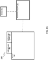
- Die 1A und 1B stellen Blockdiagramme von Systemen dar, bei denen eine Kamerakalibrierungsverifizierung gemäß Ausführungsformen hierin ausgeführt wird.
- 1C stellt ein Blockdiagramm eines Robotersteuersystems dar, das konfiguriert ist, eine Kamerakalibrierungsverifizierung gemäß einer Ausführungsform hierin auszuführen.
- 1D stellt ein Blockdiagramm einer Kamera dar, für die eine Kamerakalibrierung gemäß einer Ausführungsform hierin ausgeführt wird.
- 2 stellt ein System dar, das einen Roboter veranschaulicht, der gemäß einer Ausführungsform hierin basierend auf Kamerakalibrierinformationen, die von der Kamerakalibrierung erlangt sind, gesteuert wird.
- 3 zeigt ein System zur Ausführung einer Kamerakalibrierung, gemäß einer Ausführungsform hierin.
- Die 4A und 4B stellen ein Ablaufdiagramm bereit, das ein Verfahren zum Ausführen einer Kamerakalibrierungsverifizierung gemäß einer Ausführungsform hierin veranschaulicht.
- Die 5A und 5B veranschaulichen ein System, in dem ein Verifizierungssymbol an einem Roboter angeordnet ist, wobei das Verifizierungssymbol verwendet wird, um eine Kamerakalibrierungsverifizierung gemäß einer Ausführungsform hierin auszuführen.
- 5C zeigt ein Beispiel für ein Verifizierungssymbol gemäß einer Ausführungsform hierin.
- Die 6A-6B zeigen Beispiele gemäß einer Ausführungsform hierin von Referenzorten, an denen entsprechende Bilder eines Verifizierungssymbols erfasst werden.
- 7A zeigt ein Beispiel des Bestimmens einer Referenzbildkoordinate gemäß einer Ausführungsform hierin.
- 7B zeigt ein Beispiel des Bestimmens einer Verifizierungsbildkoordinate gemäß einer Ausführungsform hierin.
- 8 veranschaulicht eine beispielhafte Zeitachse für eine Kamerakalibrierungsverifizierung, gemäß einer Ausführungsform hierin.
- 9 stellt ein Ablaufdiagramm bereit, das ein Verfahren zum Ausführen einer Kamerakalibrierungsverifizierung gemäß einer Ausführungsform hierin veranschaulicht.
The foregoing and other features, objects, and advantages of the invention will become apparent from the following description of embodiments as illustrated in the accompanying drawings. The accompanying drawings, which are incorporated herein and form a part of the specification, also serve to explain the principles of the invention and to enable one of ordinary skill in the art to make and use the invention. The drawings are not to scale. - The 1A and 1B FIG. 12 depicts block diagrams of systems in which camera calibration verification is performed in accordance with embodiments herein.
- 1C FIG. 10 illustrates a block diagram of a robotic control system configured to perform camera calibration verification according to an embodiment herein.
- 1D FIG. 10 illustrates a block diagram of a camera for which camera calibration is performed in accordance with an embodiment herein.
- 2 FIG. 10 depicts a system illustrating a robot controlled based on camera calibration information obtained from camera calibration, according to an embodiment herein.
- 3 Figure 12 shows a system for performing camera calibration, according to an embodiment herein.
- The 4A and 4B provide a flow diagram illustrating a method for performing camera calibration verification according to an embodiment herein.
- The 5A and 5B illustrate a system in which a verification icon is placed on a robot, the verification icon being used to perform camera calibration verification according to an embodiment herein.
- 5C Figure 12 shows an example of a verification icon according to an embodiment herein.
- The 6A-6B show examples according to an embodiment herein of reference locations at which corresponding images of a verification symbol are captured.
- 7A Figure 12 shows an example of determining a reference image coordinate according to an embodiment herein.
- 7B Figure 10 shows an example of determining a verification image coordinate according to an embodiment herein.
- 8th FIG. 10 illustrates an exemplary timeline for camera calibration verification, according to an embodiment herein.
- 9 provides a flow diagram illustrating a method for performing camera calibration verification according to an embodiment herein.
Die folgende ausführliche Beschreibung ist ihrer Natur nach lediglich beispielhaft und beabsichtigt nicht, die Erfindung oder die Anmeldung und Verwendungen davon zu begrenzen. Weiterhin besteht keine Absicht, an eine ausdrückliche oder implizite Theorie gebunden zu sein, die in dem vorstehenden technischen Gebiet, dem allgemeinen Stand der Technik, der Kurzdarstellung oder in der folgenden detaillierten Beschreibung dargestellt ist.The following detailed description is merely exemplary in nature and is not intended to limit the invention or the application and uses thereof. Furthermore, there is no intention to be bound by any expressed or implied theory appearing in the preceding technical field, the general state of the art, the summary or the following detailed description.
Hierin beschriebene Ausführungsformen betreffen das Verifizieren und/oder Aktualisieren einer Kamerakalibrierung, die verwendet wird, um einen Roboter zu steuern, wie beispielsweise einen Roboter, der in einem Warenlager, einem Produktionsbetrieb oder in einer anderen Umgebung verwendet wird. Die Kalibrierung kann als Kamerakalibrierung bezeichnet werden und kann durch z.B. ein Robotersteuersystem (auch als Robotersteuerung bezeichnet) ausgeführt werden, um Kalibrierinformationen zu erzeugen, die eine Fähigkeit des Robotersteuersystems erleichtern, den Roboter basierend auf durch die Kamera erfasste (z. B. fotografierte) Bilder zu steuern. Der Roboter kann zum Beispiel verwendet werden, um ein Paket in einem Warenlager aufzunehmen, wobei das Platzieren eines Roboterarm oder einer anderen Komponente des Roboters auf durch die Kamera erfassten Bildern des Pakets basieren kann. In diesem Fall können die Kamerakalibrierinformationen zusammen mit den Bildern des Pakets verwendet werden, um beispielsweise einen Ort und eine Ausrichtung des Pakets relativ zu dem Roboterarm des Roboters zu bestimmen. Die Kamerakalibrierung kann das Bestimmen entsprechender Abschätzungen von intrinsischen Kameraparametern der Kamera (die auch als interne Parameter bezeichnet sein können) und das Bestimmen einer Abschätzung einer Beziehung zwischen der Kamera und ihrer äußeren Umgebung einbeziehen. Ein intrinsischer Parameter der Kamera kann einen oder mehrere Parameterwerte, wie beispielsweise eine Matrix, einen Vektor oder einen skalaren Wert, aufweisen. Weitere Beispiele für einen intrinsischen Parameter sind eine Projektionsmatrix und ein Verzerrungsparameter. In einem Fall kann die Kamerakalibrierung das Bestimmen der Kameraposition in Bezug auf eine feste Position in einer externen Umgebung umfassen, was als Transformationsfunktion ausgedrückt werden kann, welche die Beziehung zwischen der Kamera und der festen Position in der externen Umgebung darstellt. In einigen Fällen kann die Kamerakalibrierung mithilfe eines Kalibriermusters ausgeführt werden, das Musterelemente, die an definierten Orten auf dem Kalibriermuster angeordnet sein können, aufweisen kann. Die Kamera kann ein Bild der Musterelemente des Kalibriermusters (auch als Kalibrierbild bezeichnet) erfassen und die Kamerakalibrierung kann basierend auf dem Vergleichen eines Bildes der Musterelemente mit den definierten Orten der Musterelemente ausgeführt werden. Die Kamerakalibrierung wird in der US 10 369 698 B1 näher erläutert.Embodiments described herein relate to verifying and / or updating a camera calibration used to control a robot, such as a robot used in a warehouse, manufacturing facility, or other environment. The calibration can be referred to as camera calibration and can be performed by, for example, a robot control system (also referred to as a robot controller) to generate calibration information that facilitates an ability of the robot control system to control the robot based on images captured (e.g., photographed) by the camera to control. For example, the robot can be used to pick up a package in a warehouse, where the placement of a robotic arm or other component of the robot can be based on images of the package captured by the camera. In this case, the camera calibration information can be used together with the images of the package, for example to determine a location and an orientation of the package relative to the robot arm of the robot. The camera calibration may involve determining appropriate estimates of intrinsic camera parameters of the camera (which may also be referred to as internal parameters) and determining an estimate of a relationship between the camera and its external environment. An intrinsic parameter of the camera can have one or more parameter values, such as a matrix, a vector or a scalar value. Further examples of an intrinsic parameter are a projection matrix and a distortion parameter. In one case, camera calibration may include determining the camera position with respect to a fixed position in an external environment, which can be expressed as a transformation function representing the relationship between the camera and the fixed position in the external environment. In some cases, the camera calibration can be carried out with the aid of a calibration pattern, which can have pattern elements that can be arranged at defined locations on the calibration pattern. The camera can capture an image of the pattern elements of the calibration pattern (also referred to as a calibration image) and the camera calibration can be carried out based on the comparison of an image of the pattern elements with the defined locations of the pattern elements. The camera calibration is done in the US 10 369 698 B1 explained in more detail.
Wie vorstehend erwähnt, bezieht sich ein Aspekt der vorliegenden Offenbarung auf die Verifizierung, ob eine zu einem früheren Zeitpunkt ausgeführte Kamerakalibrierung auch zu einem späteren Zeitpunkt noch korrekt ist. Die zu einem früheren Zeitpunkt ausgeführte Kamerakalibrierung kann Kamerakalibrierinformationen erzeugen, die eine Eigenschaft der Kamera zu diesem Zeitpunkt widerspiegeln, wie beispielsweise einen intrinsischen Parameter der Kamera oder eine Beziehung zwischen der Kamera und ihrer äußeren Umgebung zu diesem Zeitpunkt. In einigen Fällen kann eine frühere Kamerakalibrierung mit der Zeit an Genauigkeit verlieren, da sich die Eigenschaft der Kamera im Laufe der Zeit ändern kann. In einem ersten Beispiel kann sich ein intrinsischer Parameter der Kamera im Laufe der Zeit ändern. Eine solche Veränderung kann z. B. durch eine Temperaturänderung verursacht werden, welche eine Form eines Gehäuses und/oder einer Linse der Kamera verändert. In einem zweiten Beispiel kann sich eine Beziehung zwischen der Kamera und ihrer äußeren Umgebung im Laufe der Zeit ändern. Die Kamera kann sich beispielsweise in ihrer Position oder Ausrichtung relativ zu z. B. einer Basis des Roboters oder einem Ort in einem Warenlager verschieben. Eine solche Veränderung kann z. B. durch eine Temperaturänderung, die eine Komponente, die zur Befestigung der Kamera verwendet wird, ausdehnt oder zusammenzieht, durch eine Person oder einen anderen Gegenstand, der gegen die Kamera stößt, durch eine Vibration in der äußeren Umgebung der Kamera (z. B. einem Warenlager), durch eine Kraft durch das Eigengewicht der Kamera (d. h. durch Schwerkraft) oder durch einen anderen Faktor verursacht werden. Diese Änderungen können dazu führen, dass die Kamerakalibrierinformationen veraltet sind, und die Verwendung dieser Kamerakalibrierinformationen zur Positionierung eines Roboterarms oder einer anderen Komponente des Roboters kann zu einem späteren Zeitpunkt zu Fehlern führen. Wenn sich eine mit der Kamera verbundene Eigenschaft im Laufe der Zeit geändert hat, aber die Kamerakalibrierinformationen nicht aktualisiert werden, um eine solche Änderung widerzuspiegeln, kann mit anderen Worten der Roboter basierend auf veralteten oder anderweitig falschen Kamerakalibrierinformationen arbeiten und dadurch unerwünschte Fehler im Roboterbetrieb verursachen. Um der Möglichkeit entgegenzuwirken, dass Änderungen bezüglich einer oder mehrerer Eigenschaften der Kamera auftreten können, kann ein Robotersteuersystem automatisch eine Verifizierung durchführen, die detektiert, wenn die Kamerakalibrierinformationen von einer Kamerakalibrierung nicht mehr ausreichend korrekt sind. Das Detektieren eines solchen Zustands kann einen Hinweis auf eine Veränderung bezüglich einer Eigenschaft der Kamera geben. Wenn bei der Verifizierung festgestellt wird, dass die Kamerakalibrierinformationen nicht mehr ausreichend korrekt sind, kann das Robotersteuersystem die Kamerakalibrierung erneut ausführen, um aktualisierte Kamerakalibrierinformationen zu bestimmen, die eine aktuellere Eigenschaft oder Eigenschaften der Kamera widerspiegeln können. Die aktualisierten Kamerakalibrierinformationen können zum Steuern der Platzierung des Roboterarms oder eines anderen Aspekts des Roboterbetriebs verwendet werden. Dementsprechend wird eine automatische Kamerakalibrierungsverifizierung und/oder eine Aktualisierung der Kamerakalibrierung ausgeführt, um sicherzustellen, dass der Roboter basierend auf korrekten Informationen über eine oder mehrere mit der Kamera verbundene Eigenschaften arbeitet.As mentioned above, one aspect of the present disclosure relates to the verification of whether a camera calibration performed at an earlier point in time is still correct at a later point in time. The camera calibration performed at an earlier point in time can generate camera calibration information that reflects a property of the camera at that point in time, such as an intrinsic parameter of the camera or a relationship between the camera and its external environment at that point in time. In some cases, a previous camera calibration may lose accuracy over time as the characteristics of the camera can change over time. In a first example, an intrinsic parameter of the camera can change over time. Such a change can e.g. B. caused by a temperature change, which changes a shape of a housing and / or a lens of the camera. In a second example, a relationship between the camera and its external environment can change over time. The camera can, for example, in its position or orientation relative to z. B. move a base of the robot or a location in a warehouse. Such a change can e.g. B. by a change in temperature that expands or contracts a component used to mount the camera, by a person or other object striking the camera, by a vibration in the external environment of the camera (e.g. a warehouse), a force caused by the weight of the camera (i.e. gravity), or some other factor. These changes could render the camera calibration information out of date, and using this camera calibration information to position a robot arm or other component of the robot could lead to errors at a later date. In other words, if a property associated with the camera has changed over time, but the camera calibration information is not updated to reflect such a change, the robot may operate based on outdated or otherwise incorrect camera calibration information, causing undesirable errors in the robot's operation. In order to counteract the possibility that changes in one or more properties of the camera can occur, a robot control system can automatically carry out a verification which detects when the camera calibration information from a camera calibration is no longer sufficiently correct. The detection of such a condition can give an indication of a change in a property of the camera. If the verification determines that the camera calibration information is no longer sufficiently correct, the robotic control system can rerun the camera calibration to determine updated camera calibration information that may reflect a more recent property or properties of the camera. The updated camera calibration information can be used to control the placement of the robotic arm or a other aspect of robot operation. Accordingly, an automatic camera calibration verification and / or an update of the camera calibration is performed to ensure that the robot is operating based on correct information about one or more properties associated with the camera.
Ein Aspekt der Ausführungsformen hierin betrifft die Verifizierung einer Kamerakalibrierung für eine Kamera durch Vergleichen eines von der Kamera erfassten Referenzbildes mit einem von der Kamera erfassten Verifizierungsbild. In einigen Fällen kann das Referenzbild ein Bild eines Objekts sein, das erfasst wurde, als das Objekt zu einem früheren Zeitpunkt an einem bestimmten Ort ist, und das Verifizierungsbild kann ein Bild des Objekts sein, das zu einem späteren Zeitpunkt an dem gleichen Ort erfasst wurde. Bei der Verifizierung kann bestimmt werden, ob es eine zu große Abweichung zwischen dem Referenzbild und dem Verifizierungsbild gibt, wie beispielsweise ob die Abweichung einen bestimmten Schwellenwert überschreitet. In einigen Implementierungen kann das Objekt ein Verifizierungssymbol sein. Spezifischer kann ein Roboterarm oder eine andere Komponente des Roboters ein Verifizierungssymbol aufweisen, das zur Kamerakalibrierungsverifizierung verwendet wird. Sowohl das Referenzbild als auch das Verifizierungsbild können das Verifizierungssymbol erfassen oder anderweitig umfassen, und das Robotersteuersystem kann die zwei Bilder durch Vergleichen eines Erscheinungsbildes des Verifizierungssymbols in dem Referenzbild mit einem Erscheinungsbild des Verifizierungssymbols in dem Verifizierungsbild vergleichen. Nachdem das Robotersteuersystem beispielsweise eine Kamerakalibrierung ausgeführt hat, die zu einem bestimmten Zeitpunkt Kamerakalibrierinformationen erzeugt, kann das Robotersteuersystem den Roboterarm (z. B. über einen Bewegungsbefehl) derart steuern, dass das Verifizierungssymbol an eine Reihe von vordefinierten Orten innerhalb des Sichtfelds der Kamera (auch als Kamerasichtfeld der Kamera bezeichnet) bewegt wird, wobei diese Orte als eine Reihe von Referenzorten für die Verifizierung verwendet werden können. Die Kamera kann entsprechende Referenzbilder des Verifizierungssymbols an der Reihe von Referenzorten erfassen. In einigen Fällen können die Referenzbilder unmittelbar nach der Kamerakalibrierung erfasst werden. Die Bewegung des Roboterarms, oder insbesondere ein Bewegungsbefehl, der zur Bewegung des Roboterarms verwendet wird, kann auf den Kamerakalibrierinformationen von der gerade ausgeführten Kamerakalibrierung basieren oder unabhängig von den Kamerakalibrierinformationen sein. In einigen Fällen können die Referenzbilder erfasst werden, bevor der Roboter den Roboterbetrieb beginnt. Nachdem die Referenzbilder erfasst wurden, kann der Roboter als bereit angesehen werden, einen Roboterbetrieb zur Ausführung einer Aufgabe zu beginnen, und das Robotersteuersystem kann z. B. die Positionierung des Roboterarms basierend auf anschließend von der Kamera erfassten Bildern steuern.One aspect of the embodiments herein relates to the verification of a camera calibration for a camera by comparing a reference image captured by the camera with a verification image captured by the camera. In some cases, the reference image may be an image of an object captured when the object was in a particular location earlier, and the verification image may be an image of the object captured in the same location at a later time . During the verification, it can be determined whether there is too great a deviation between the reference image and the verification image, such as, for example, whether the deviation exceeds a certain threshold value. In some implementations, the object can be a verification icon. More specifically, a robot arm or other component of the robot may have a verification icon that is used for camera calibration verification. Both the reference image and the verification image can capture or otherwise include the verification symbol, and the robotic control system can compare the two images by comparing an appearance of the verification symbol in the reference image with an appearance of the verification symbol in the verification image. After the robot control system has performed a camera calibration, for example, which generates camera calibration information at a certain point in time, the robot control system can control the robot arm (e.g. via a movement command) in such a way that the verification symbol is in a number of predefined locations within the field of view of the camera (including referred to as the camera's field of view), and these locations can be used as a set of reference locations for verification. The camera can capture corresponding reference images of the verification symbol at the series of reference locations. In some cases, the reference images can be captured immediately after camera calibration. The movement of the robot arm, or in particular a movement command that is used to move the robot arm, can be based on the camera calibration information from the camera calibration that has just been carried out, or it can be independent of the camera calibration information. In some cases, the reference images can be captured before the robot starts robot operation. After the reference images have been captured, the robot can be considered ready to start robot operation to perform a task, and the robot control system can e.g. B. control the positioning of the robot arm based on images subsequently captured by the camera.
Wie vorstehend erwähnt, können die Referenzbilder mit anschließend erfassten Verifizierungsbildern verglichen werden. Bei einer Ausführungsform können die Verifizierungsbilder während einer oder mehrerer Ruhezeiten erfasst werden, die von dem Robotersteuersystem detektiert werden. Insbesondere kann der Roboter zu Beginn des Roboterbetriebs mit der Ausführung von Roboteraufgaben beginnen (z. B. durch Interaktion mit Paketen oder anderen Objekten). Während der Roboter den Roboterbetrieb ausführt, kann das Robotersteuersystem eine oder mehrere Ruhezeiten für den Roboter erkennen. In einigen Fällen kann die Ruhezeit ein Zeitraum sein, in dem der Roboter während des Roboterbetriebs frei von der Ausführung einer Roboteraufgabe ist. In einigen Fällen kann das Robotersteuersystem den Roboterbetrieb basierend auf dem Detektieren oder anderweitigen Antizipieren von Objekten, mit denen der Roboter interagieren muss, planen und eine Ruhezeit basierend auf dem Detektieren oder anderweitigen Antizipieren der Abwesenheit von Objekten, mit denen der Roboter interagieren muss, detektieren.As mentioned above, the reference images can be compared with subsequently acquired verification images. In one embodiment, the verification images may be captured during one or more rest periods that are detected by the robotic control system. In particular, at the beginning of robot operation, the robot can begin performing robot tasks (e.g. by interacting with packages or other objects). While the robot is performing the robot operation, the robot control system can detect one or more rest periods for the robot. In some cases, the idle time can be a period of time during which the robot is free from performing a robot task. In some cases, the robot control system may schedule robot operation based on detecting or otherwise anticipating objects with which the robot must interact and detect a rest time based on detecting or otherwise anticipating the absence of objects with which the robot must interact.
Während der bzw. den Ruhezeit(en) kann das Robotersteuersystem den Roboterarm oder andere Komponenten des Roboters (z. B. über einen Bewegungsbefehl) derart steuern, dass er sich zu den Referenzorten bewegt und (z. B. über einen Kamerabefehl) an jedem der Referenzorte ein entsprechendes Verifizierungsbild erfasst. Wenn der Roboter ein Verifizierungssymbol aufweist, kann das Robotersteuersystem den Roboterarm spezifischer steuern, um das Verifizierungssymbol zu den Referenzorten zu bewegen und die Verifizierungsbilder zu erfassen. Anschließend kann das Robotersteuersystem feststellen, wie stark die entsprechenden Verifizierungsbilder von entsprechenden Referenzbildern an entsprechenden Referenzpunkten abweichen. In einigen Fällen kann die Abweichung zwischen den Verifizierungsbildern und entsprechenden Referenzbildern als Abweichungsparameter ausgedrückt werden. Wenn ein Wert des Abweichungsparameters (auch als ein Abweichungsparameterwert bezeichnet) einen definierten Schwellenwert für den Abweichungsparameter (der auch als definierter Abweichungsschwellenwert bezeichnet werden kann) überschreitet, kann das Robotersteuersystem eine zusätzliche Kamerakalibrierung durchführen, um aktualisierte Kamerakalibrierinformationen für die Kamera zu bestimmen. Wenn ein Abweichungsparameterwert den definierten Abweichungsschwellenwert überschreitet, kann diese Bedingung anzeigen, dass die Verwendung alter Kamerakalibrierinformationen zu einer unerwünschten Fehlermenge im Roboterbetrieb führen kann. Daher kann in einigen Fällen der Roboterbetrieb pausiert oder gestoppt werden, während die zusätzliche Kalibrierung ausgeführt wird (die Pause kann als eine weitere Ruhezeit angesehen werden). Nachdem die zusätzliche Kalibrierung abgeschlossen ist, kann ein neuer Satz von Referenzbildern erfasst werden, und der Roboterbetrieb kann mit den aktualisierten Kamerakalibrierinformationen fortgesetzt werden. Während einer oder mehrerer anschließender Ruhezeiten kann ein neuer Satz von Verifizierungsbildern erfasst werden und das Robotersteuersystem kann die Verifizierung der zusätzlichen Kamerakalibrierung durch Vergleichen des neuen Satzes von Referenzbildern mit dem neuen Satz von Verifizierungsbildern ausführen.During the rest period (s), the robot control system can control the robot arm or other components of the robot (e.g. via a movement command) in such a way that it moves to the reference locations and at each (e.g. via a camera command) of the reference locations captures a corresponding verification image. When the robot has a verification icon, the robot control system can more specifically control the robot arm to move the verification icon to the reference locations and capture the verification images. The robot control system can then determine how much the corresponding verification images deviate from corresponding reference images at corresponding reference points. In some cases, the deviation between the verification images and corresponding reference images can be expressed as a deviation parameter. If a value of the deviation parameter (also referred to as a deviation parameter value) exceeds a defined threshold value for the deviation parameter (which can also be referred to as a defined deviation threshold), the robot control system can perform an additional camera calibration to determine updated camera calibration information for the camera. When a deviation parameter value exceeds the defined deviation threshold, this condition can indicate that using old camera calibration information can lead to an undesirable amount of error in robot operation. Therefore, in in some cases robot operation may be paused or stopped while the additional calibration is in progress (the pause can be viewed as another rest period). After the additional calibration is complete, a new set of reference images can be captured and robot operation can continue with the updated camera calibration information. During one or more subsequent rest periods, a new set of verification images can be captured and the robotic control system can perform the verification of the additional camera calibration by comparing the new set of reference images with the new set of verification images.
Wie vorstehend erwähnt, kann das Robotersteuersystem eine zusätzliche Kamerakalibrierung ausführen, wenn ein Abweichungsparameterwert den definierten Abweichungsschwellenwert überschreitet. Wenn der Abweichungsparameterwert den Abweichungsschwellenwert nicht überschreitet, kann der Roboterbetrieb nach einer Ruhezeit fortgesetzt werden, ohne dass das Robotersteuersystem eine zusätzliche Kalibrierung ausführt. In diesem Szenario kann die Kamera an den entsprechenden Referenzstandorten während einer oder mehrerer späterer Ruhezeiten einen neuen Satz von Verifizierungsbildern erfassen. Wenn der neue Satz von Verifizierungsbildern erfasst ist, kann das Robotersteuersystem erneut eine Kamerakalibrierungsverifizierung ausführen, indem es bestimmt, wie sehr der neue Satz von Verifizierungsbildern von den entsprechenden Referenzbildern an den entsprechenden Referenzorten abweicht.As mentioned above, the robot control system can perform an additional camera calibration if a deviation parameter value exceeds the defined deviation threshold value. If the deviation parameter value does not exceed the deviation threshold value, the robot operation can be continued after a rest period without the robot control system performing additional calibration. In this scenario, the camera can capture a new set of verification images at the appropriate reference locations during one or more subsequent rest periods. When the new set of verification images is captured, the robot control system can again perform camera calibration verification by determining how much the new set of verification images deviates from the corresponding reference images at the corresponding reference locations.
Wie vorstehend erwähnt, kann der Roboterarm ein Verifizierungssymbol, wie beispielsweise ein Ringmuster, aufweisen und das Verifizierungssymbol kann von den Referenzbildern und den Verifizierungsbildern erfasst oder anderweitig darin enthalten sein. Bei einer Ausführungsform kann das Robotersteuersystem eine Abweichung zwischen den Referenzbildern und den entsprechenden Verifizierungsbildern basierend auf entsprechenden Orten, an denen das Verifizierungssymbol in den Referenzbildern erscheint, und basierend auf entsprechenden Orten, an denen das Verifizierungssymbol in den Verifizierungsbildern erscheint, bestimmen. Das Robotersteuersystem kann beispielsweise eine Referenzbildkoordinate für jeden Referenzort bestimmen. Die Referenzbildkoordinate für einen bestimmten Ort kann eine Koordinate sein, an der das Verifizierungssymbol in einem Referenzbild erscheint, das erfasst wurde, als das Verifizierungssymbol an diesem Referenzort platziert wurde. Insbesondere kann die Referenzbildkoordinate mit einem bestimmten Referenzort verbunden sein und sich auf eine Bildkoordinate beziehen, an der ein Verifizierungssymbol in einem Referenzbild erscheint, wobei das Referenzbild von einer Kamera erfasst wurde, als das Verifizierungssymbol an diesem Referenzort platziert wurde. In dem vorstehenden Beispiel kann sich die Bildkoordinate auf eine Koordinate in einem Bild, wie beispielsweise eine Pixelkoordinate, beziehen. Wenn das Robotersteuersystem anschließend das Verifizierungssymbol wieder an einem bestimmten Referenzort platziert und ein entsprechendes Verifizierungsbild erhält, kann das Robotersteuersystem eine Verifizierungsbildkoordinate bestimmen. Die Verifizierungsbildkoordinate kann auch mit dem Referenzort verbunden sein und sich auf eine Bildkoordinate (z. B. eine Pixelkoordinate) beziehen, an der das Verifizierungssymbol im Verifizierungsbild erscheint, wobei das Verifizierungsbild von der Kamera erfasst wurde, als das Verifizierungssymbol am Referenzort platziert wurde. Das Robotersteuersystem kann die mit einem bestimmten Referenzort verbundene Referenzbildkoordinate mit einer mit dem gleichen Referenzort verbundenen Verifizierungsbildkoordinate vergleichen. Dieser Vergleich kann für jeden Referenzort ausgeführt werden, an dem ein Verifizierungsbild und ein Referenzbild erfasst wurden.As mentioned above, the robot arm can have a verification symbol, such as a ring pattern, and the verification symbol can be captured from or otherwise contained in the reference images and the verification images. In one embodiment, the robot control system may determine a deviation between the reference images and the corresponding verification images based on respective locations where the verification symbol appears in the reference images and based on corresponding locations where the verification symbol appears in the verification images. The robot control system can, for example, determine a reference image coordinate for each reference location. The reference image coordinate for a particular location may be a coordinate at which the verification symbol appears in a reference image captured when the verification symbol was placed at that reference location. In particular, the reference image coordinate can be linked to a specific reference location and relate to an image coordinate at which a verification symbol appears in a reference image, the reference image being captured by a camera when the verification symbol was placed at this reference location. In the above example, the image coordinate can refer to a coordinate in an image, such as a pixel coordinate. If the robot control system then places the verification symbol again at a certain reference location and receives a corresponding verification image, the robot control system can determine a verification image coordinate. The verification image coordinate can also be associated with the reference location and refer to an image coordinate (e.g. a pixel coordinate) at which the verification symbol appears in the verification image, the verification image being captured by the camera when the verification symbol was placed at the reference location. The robot control system can compare the reference image coordinate associated with a certain reference location with a verification image coordinate associated with the same reference location. This comparison can be carried out for each reference location at which a verification image and a reference image were acquired.
In einem Fall kann eine Referenzbildkoordinate, an der ein Verifizierungssymbol in einem Referenzbild erscheint, eine Koordinate eines Zentrums des Verifizierungssymbols in dem Referenzbild sein (was auch als Zentrumskoordinate des Verifizierungssymbols in dem Referenzbild bezeichnet wird). In ähnlicher Weise kann eine Verifizierungsbildkoordinate, an der das Verifizierungssymbol in einem Verifizierungsbild erscheint, eine Koordinate eines Zentrums des Verifizierungssymbols in dem Verifizierungsbild sein (was auch als Zentrumskoordinate des Verifizierungssymbols in dem Verifizierungsbild bezeichnet wird). Für jeden Referenzort, an dem sich der Roboterarm und/oder das Verifizierungssymbol bei der Erfassung eines entsprechenden Verifizierungsbildes befand, kann das Robotersteuersystem eine Abweichung zwischen der mit dem Referenzort verbundenen Referenzbildkoordinate und der mit dem gleichen Referenzort verbundenen Verifizierungsbildkoordinate bestimmen. Wenn der Roboterarm und/oder das Verifizierungssymbol an mehreren Referenzorten platziert wurde, kann das Robotersteuersystem für die mehreren Referenzorte entsprechende Abweichungsbeträge zwischen entsprechenden Referenzbildkoordinaten und entsprechenden Verifizierungsbildkoordinaten bestimmen. Das Robotersteuersystem kann ferner einen Wert eines Abweichungsparameters bestimmen, der auf den entsprechenden Abweichungsbeträgen zwischen den Referenzbildkoordinaten und den entsprechenden Verifizierungsbildkoordinaten für entsprechende Referenzorte basiert.In one case, a reference image coordinate at which a verification symbol appears in a reference image may be a coordinate of a center of the verification symbol in the reference image (which is also referred to as a center coordinate of the verification symbol in the reference image). Similarly, a verification image coordinate at which the verification symbol appears in a verification image may be a coordinate of a center of the verification symbol in the verification image (which is also referred to as a center coordinate of the verification symbol in the verification image). For each reference location at which the robot arm and / or the verification symbol was when a corresponding verification image was captured, the robot control system can determine a deviation between the reference image coordinate associated with the reference location and the verification image coordinate associated with the same reference location. If the robot arm and / or the verification symbol have been placed at a plurality of reference locations, the robot control system can determine corresponding deviation amounts between corresponding reference image coordinates and corresponding verification image coordinates for the plurality of reference locations. The robot control system may further determine a value of a deviation parameter based on the respective deviation amounts between the reference image coordinates and the respective verification image coordinates for respective reference locations.
In einem Fall kann das Verifizierungssymbol mehrere Formen umfassen, die konzentrisch zueinander sind, sodass sich die entsprechenden Mitten der mehreren Formen im Verifizierungssymbol am gleichen oder im Wesentlichen dem gleichen Ort befinden. Das Verifizierungssymbol kann zum Beispiel ein Ringmuster sein, das zwei oder mehr konzentrische Kreise umfasst. Wenn in einigen Fällen die Referenzbildkoordinate eines Verifizierungssymbols eine Mittenkoordinate des Verifizierungssymbols in einem Referenzbild ist, kann das Robotersteuersystem eine Mittenkoordinate des Verifizierungssymbols basierend auf entsprechenden Mittenkoordinaten der mehreren Formen in dem Referenzbild bestimmen, wobei die Mittenkoordinate einer bestimmten Form eine Koordinate eines Zentrums dieser Form ist. Wenn das Verifizierungssymbol ein Ringmuster ist, kann die Mittenkoordinate des Ringmusters in einem Referenzbild als Mittelwert einer Mittenkoordinate eines ersten Kreises, der das Ringmuster bildet, und einer Mittenkoordinate eines zweiten Kreises, der das Ringmuster in dem Referenzbild bildet, bestimmt werden. In ähnlicher Weise kann eine Mittenkoordinate eines Verifizierungssymbols in einem Verifizierungsbild basierend auf den entsprechenden Mittenkoordinaten der mehreren Formen, die das Verifizierungssymbol im Verifizierungsbild bilden, bestimmt werden. In einigen Fällen kann die Verwendung mehrerer Formen zum Bilden des Verifizierungssymbols eine Genauigkeit der Verifizierung verbessern. Beispielsweise kann die Verwendung der entsprechenden Mittenkoordinaten der mehreren Formen in einem Bild zum Bestimmen einer Mittenkoordinate des Verifizierungssymbols eine Robustheit der Verifizierung gegenüber Bildrauschen verbessern. Wenn ein Bild des Verifizierungssymbols Bildrauschen umfasst, kann das Bildrauschen insbesondere eine Genauigkeit verringern, mit der das Robotersteuersystem eine Mittenkoordinate einer bestimmten Form des Verifizierungssymbols detektiert. Wenn die Mittenkoordinate dieser Form jedoch mit einer Mittenkoordinate einer anderen Form gemittelt wird, um eine Mittenkoordinate des Verifizierungssymbols zu bestimmen, kann die gemittelte Mittenkoordinate eine Auswirkung des Bildrauschens reduzieren. Dadurch kann eine Genauigkeit bei der Bestimmung der Mittenkoordinate des Verifizierungssymbols verbessert werden.In one case, the verification symbol may include multiple shapes that are concentric with each other such that the respective centers of the multiple shapes in the verification symbol are at or near the same are essentially the same location. For example, the verification symbol can be a ring pattern that includes two or more concentric circles. In some cases, when the reference image coordinate of a verification symbol is a center coordinate of the verification symbol in a reference image, the robot control system can determine a center coordinate of the verification symbol based on corresponding center coordinates of the plurality of shapes in the reference image, the center coordinate of a certain shape being a coordinate of a center of that shape. When the verification symbol is a ring pattern, the center coordinate of the ring pattern in a reference image can be determined as an average of a center coordinate of a first circle forming the ring pattern and a center coordinate of a second circle forming the ring pattern in the reference image. Similarly, a center coordinate of a verification symbol in a verification image can be determined based on the corresponding center coordinates of the plurality of shapes that make up the verification symbol in the verification image. In some cases, using multiple shapes to form the verification symbol can improve verification accuracy. For example, using the corresponding center coordinates of the plurality of shapes in an image to determine a center coordinate of the verification symbol can improve robustness of the verification against image noise. In particular, when an image of the verification symbol includes image noise, the image noise can reduce an accuracy with which the robot control system detects a center coordinate of a certain shape of the verification symbol. However, when the center coordinate of this shape is averaged with a center coordinate of another shape to determine a center coordinate of the verification symbol, the averaged center coordinate can reduce an effect of the image noise. As a result, accuracy in determining the center coordinate of the verification symbol can be improved.
In einem Fall kann das Verifizierungssymbol mehrere Regionen mit unterschiedlichen entsprechenden Farben aufweisen, wobei entsprechende Bereiche der mehreren Regionen ein bestimmtes und definiertes Verhältnis aufweisen können. Beispielsweise kann das Verifizierungssymbol eine erste Region mit einer ersten Farbe (z. B. schwarz) und eine zweite Region mit einer zweiten Farbe (z. B. weiß) aufweisen, wobei ein Verhältnis eines Bereichs der ersten Region zu einem Bereich der zweiten Region definiert oder anderweitig bekannt ist. Das eindeutige Verhältnis kann die Identifizierung des Verifizierungssymbols in einem Bild erleichtern, insbesondere wenn das Bild andere Merkmale, wie beispielsweise Punkte eines Kalibriermusters, erfasst oder anderweitig umfasst. Der Roboterarm, der das Verifizierungssymbol bewegt, kann beispielsweise auch das Kalibriermuster auf dem Roboterarm angeordnet aufweisen. Das Robotersteuersystem kann das Verhältnis verwenden, um das Verifizierungssymbol von den Punkten des Kalibriermusters zu unterscheiden. Da das Verhältnis der Bereiche der verschiedenen Regionen des Verifizierungssymbols als ein eindeutiges Verhältnis definiert ist, kann das Robotersteuersystem das Verifizierungssymbol in einem Bild basierend auf dem definierten Verhältnis identifizieren. Bei der Identifizierung des in einem Bild erscheinenden Verifizierungssymbols kann das Robotersteuersystem das Verifizierungssymbol von dem Kalibriermuster oder einem anderen Merkmal basierend auf dem definierten Verhältnis unterscheiden. In einigen Fällen kann das Verifizierungssymbol im Bild als ein Teil des Bildes identifiziert werden, der die mehreren Regionen mit unterschiedlichen entsprechenden Farben aufweist und das definierte Verhältnis zwischen entsprechenden Bereichen der mehreren Regionen aufweist. Wenn das Robotersteuersystem oder ein anderes System oder eine Vorrichtung bestimmt, dass ein bestimmter Teil des Bildes nicht mehrere Regionen mit jeweils unterschiedlichen Farben aufweist, oder dass entsprechende Bereiche der mehreren Regionen ein anderes als das definierte Verhältnis aufweisen, kann das Robotersteuersystem bestimmen, dass der Teil des Bildes nicht das Verifizierungssymbol ist.In one case, the verification symbol can have a plurality of regions with different corresponding colors, wherein corresponding areas of the plurality of regions can have a certain and defined relationship. For example, the verification symbol can have a first region with a first color (e.g. black) and a second region with a second color (e.g. white), wherein a ratio of an area of the first region to an area of the second region defines or otherwise known. The unique relationship can facilitate the identification of the verification symbol in an image, in particular if the image captures or otherwise includes other features, such as points of a calibration pattern. The robot arm that moves the verification symbol can, for example, also have the calibration pattern arranged on the robot arm. The robot control system can use the ratio to distinguish the verification symbol from the points of the calibration pattern. Since the ratio of the areas of the various regions of the verification symbol is defined as a unique ratio, the robot control system can identify the verification symbol in an image based on the defined ratio. In identifying the verification symbol appearing in an image, the robot control system can distinguish the verification symbol from the calibration pattern or other feature based on the defined relationship. In some cases, the verification symbol in the image can be identified as a part of the image having the plurality of regions with different corresponding colors and having the defined relationship between corresponding areas of the plurality of regions. If the robotic control system or another system or device determines that a certain part of the image does not have multiple regions each having different colors, or that corresponding areas of the multiple regions have a different ratio than the defined ratio, the robotic control system can determine that the part of the image is not the verification icon.
In einem Fall kann das Robotersteuersystem die Verifizierung basierend auf einer den Roboter umgebenden Temperatur ausführen. Das Robotersteuersystem kann beispielsweise den definierten Abweichungsschwellwert basierend auf der Temperatur anpassen (d. h., einen neuen Wert für den Abweichungsschwellwert definieren). Eine Temperatur kann beispielsweise verschiedene Teile in der Kamera und/oder im Roboter beeinflussen, da einige Materialien empfindlich sein und/oder sich basierend auf einer Temperatur ausdehnen/zusammenziehen können. Eine Temperaturänderung kann bewirken, dass sich ein oder mehrere intrinsische Parameter der Kamera ändern und/oder dass sich die Beziehung zwischen der Kamera und ihrer äußeren Umgebung ändert. Bei einer Ausführungsform kann der Abweichungsschwellenwert derart eingestellt werden, dass er einen ersten Wert aufweist, wenn die Temperatur außerhalb eines definierten Bereichs liegt, während der Abweichungsschwellenwert derart eingestellt werden kann, dass er einen zweiten Wert aufweist, der niedriger ist als der erste Wert, wenn die Temperatur innerhalb des definierten Bereichs liegt. Wenn die Temperatur z. B. innerhalb eines definierten normalen Betriebstemperaturbereichs liegt (z. B. innerhalb von 10 Grad der Raumtemperatur), dann kann der Abweichungsschwellenwert der erste Wert sein. Wenn die Temperatur außerhalb des normalen Betriebstemperaturbereichs liegt, dann kann der Abweichungsschwellenwert den zweiten Wert niedriger aufweisen als der erste Wert. Der zweite Wert kann niedriger als der erste Wert sein, sodass eine zusätzliche Kamerakalibrierung leichter ausgelöst werden kann, wenn die Temperatur außerhalb des normalen Betriebsbereichs liegt, da die Temperatur außerhalb des normalen Betriebstemperaturbereichs mit größerer Wahrscheinlichkeit Änderungen an der Kamera oder ihrer Beziehung zur äußeren Umgebung und daher wahrscheinlicher Fehler beim Roboterbetrieb mit alten Kamerakalibrierinformationen verursachen kann.In one case, the robot control system can perform the verification based on a temperature surrounding the robot. The robot control system can, for example, adjust the defined deviation threshold value based on the temperature (ie, define a new value for the deviation threshold value). For example, a temperature can affect different parts in the camera and / or in the robot, as some materials are sensitive and / or can expand / contract based on temperature. A change in temperature can cause one or more intrinsic parameters of the camera to change and / or to change the relationship between the camera and its external environment. In one embodiment, the deviation threshold can be set to have a first value when the temperature is outside a defined range, while the deviation threshold can be set to have a second value that is lower than the first value when the temperature is within the defined range. If the temperature is e.g. B. is within a defined normal operating temperature range (e.g. within 10 degrees of room temperature), then the deviation threshold can be the first value. If the temperature is outside the normal operating temperature range, then the deviation threshold can have the second value lower than the first value. The second value can be lower than the first value, so that an additional camera calibration can be triggered more easily if the temperature is outside The temperature outside of the normal operating temperature range is more likely to cause changes to the camera or its relationship to the external environment and therefore more likely to cause errors in robot operation with old camera calibration information.
Bei einer Ausführungsform kann die Kamerakalibrierungsverifizierung auf nur einem einzigen Referenzort beruhen. Alternativ kann die Kamerakalibrierungsverifizierung auf mehreren Referenzorten beruhen. Bei den Referenzstandorten kann es sich um beliebige Orte im Sichtfeld einer Kamera oder um spezifische definierte Orte handeln. Die Referenzorte können beispielsweise als Orte auf einer Fläche von mindestens einer imaginären Kugel definiert werden, die in Bezug auf die Kamera konkav ist. An jedem Referenzort in diesem Szenario kann der Roboterarm derart gesteuert werden, dass er das Verifizierungssymbol positioniert, sodass das Verifizierungssymbol tangential zur Fläche der mindestens einen imaginären Kugel positioniert wird, während es der Kamera zugewandt ist. Durch diese Positionierung kann das Verifizierungssymbol vielleicht besser fotografiert oder anderweitig frontal von der Kamera erfasst werden (wobei das Verifizierungssymbol direkt der Kamera zugewandt ist), sodass ein Bild des Verifizierungssymbols eher einer Draufsicht als einer perspektivischen Ansicht des Verifizierungssymbols ähnelt. Wenn das Verifizierungssymbol beispielsweise ein Ringmuster ist, kann die Positionierung des Ringmusters tangential zur Fläche der imaginären Kugel ermöglichen, dass das resultierende Bild des Ringmusters immer noch kreisförmig anstatt elliptisch erscheint. Das resultierende Bild kann weniger oder keine perspektivische Verzerrung aufweisen (relativ zu einem Szenario, in dem das Ringmuster im Bild elliptisch erscheint). Die fehlende perspektivische Verzerrung kann eine genaue Bestimmung einer Mittenkoordinate des Ringmusters erleichtern. In einigen Fällen können die Referenzorte auf mehrere imaginäre Kugeln aufgeteilt sein, die alle in Bezug auf die Kamera konkav sind. Die mehreren imaginären Kugeln können ein gemeinsames Zentrum aufweisen und unterschiedlich groß sein, sodass jede imaginäre Kugel eine sphärische Fläche aufweist, die einen anderen entsprechenden Abstand von der Kamera aufweist. In einigen Fällen kann die Kamera ein gemeinsames Zentrum für alle imaginären Kugeln sein.In one embodiment, the camera calibration verification may be based on only a single reference location. Alternatively, the camera calibration verification can be based on multiple reference locations. The reference locations can be any locations in the field of view of a camera or specific, defined locations. The reference locations can be defined, for example, as locations on a surface of at least one imaginary sphere that is concave with respect to the camera. At each reference location in this scenario, the robotic arm can be controlled to position the verification symbol so that the verification symbol is positioned tangent to the surface of the at least one imaginary sphere while facing the camera. This positioning may allow the verification icon to be better photographed or otherwise viewed head-on by the camera (with the verification icon facing directly towards the camera) so that an image of the verification icon will resemble a top view rather than a perspective view of the verification icon. For example, if the verification symbol is a ring pattern, positioning the ring pattern tangent to the face of the imaginary sphere may allow the resulting image of the ring pattern to still appear circular rather than elliptical. The resulting image may have less or no perspective distortion (relative to a scenario where the ring pattern in the image appears elliptical). The lack of perspective distortion can facilitate an accurate determination of a central coordinate of the ring pattern. In some cases, the reference locations can be divided into several imaginary spheres, all of which are concave with respect to the camera. The plurality of imaginary spheres can have a common center and can be of different sizes such that each imaginary sphere has a spherical surface that is a different corresponding distance from the camera. In some cases the camera can be a common center for all imaginary spheres.
1A zeigt ein Blockdiagramm eines Roboterbetriebssystems 100 (auch als System 100 bezeichnet) zur Ausführung einer automatischen Kamerakalibrierung und einer automatischen Kamerakalibrierungsverifizierung. Das Roboterbetriebssystem 100 umfasst einen Roboter 150, ein Robotersteuersystem 110 (das auch als Robotersteuerung bezeichnet wird) und eine Kamera 170. Bei einer Ausführungsform kann sich das System 100 in einem Warenlager, einem Produktionsbetrieb oder in anderen Räumlichkeiten befinden. Das Robotersteuersystem 110 kann konfiguriert sein, eine Kamerakalibrierung auszuführen, die nachstehend ausführlicher beschrieben wird, um Kalibrierinformationen zu bestimmen, die später verwendet werden, um den Roboter 150 derart zu steuern, dass er einen Roboterbetrieb, wie z. B. das Aufnehmen von Paketen im Warenlager, ausführt. Das Robotersteuersystem 110 kann darüber hinaus derart konfiguriert sein, dass es eine Kamerakalibrierungsverifizierung durchführt, die ebenfalls weiter unten näher erörtert wird, um zu verifizieren, ob die Kamerakalibrierinformationen noch ausreichend genau sind. In einigen Fällen ist das Robotersteuersystem 110 konfiguriert, die Kamerakalibrierung auszuführen und den Roboter 150 zu steuern, um einen Roboterbetrieb basierend auf den Kamerakalibrierinformationen auszuführen. In einigen Fällen kann das Robotersteuersystem 110 eine einzelne Vorrichtung bilden (z. B. eine einzelne Konsole oder ein einzelner Computer), die mit dem Roboter 150 und der Kamera 170 kommuniziert. In einigen Fällen kann das Robotersteuersystem 110 mehrere Vorrichtungen umfassen. 1A Figure 3 shows a block diagram of a robot operating system 100 (also as a system 100 for performing automatic camera calibration and automatic camera calibration verification. The robot operating system 100 includes a robot 150 , a robot control system 110 (also known as a robot controller) and a camera 170 . In one embodiment, the system can 100 are in a warehouse, production facility or other premises. The robot control system 110 may be configured to perform camera calibration, described in more detail below, to determine calibration information that will later be used to identify the robot 150 in such a way that it can operate a robot, e.g. B. the picking up of packages in the warehouse. The robot control system 110 can also be configured to perform a camera calibration verification, also discussed in more detail below, to verify that the camera calibration information is still sufficiently accurate. In some cases the robot control system is 110 configured to perform camera calibration and the robot 150 to perform a robot operation based on the camera calibration information. In some cases the robot control system can 110 form a single device (e.g. a single console or a single computer) that works with the robot 150 and the camera 170 communicates. In some cases the robot control system can 110 comprise multiple devices.
In einigen Fällen kann das Robotersteuersystem 110 zum Ausführen der Kamerakalibrierung und/oder Überprüfung der Kamerakalibrierung vorgesehen sein und kann die aktuellsten Kamerakalibrierinformationen an ein anderes Steuersystem kommunizieren (das auch als eine andere Steuerung bezeichnet wird, die nicht gezeigt ist), das dann den Roboter 150 steuert, um einen Roboterbetrieb basierend auf den aktuellsten Kamerakalibrierinformationen auszuführen. Der Roboter 150 kann basierend auf Bildern, die durch die Kamera 170 erfasst werden, und auf den Kamerakalibrierinformationen positioniert werden. Insbesondere kann das Robotersteuersystem 110 in einer Ausführungsform derart konfiguriert sein, dass es basierend auf den Bildern und den Kamerakalibrierinformationen Bewegungsbefehle erzeugt und die Bewegungsbefehle an den Roboter 150 zu kommunizieren, um die Bewegung seines Roboterarms zu steuern. In einigen Fällen ist das Robotersteuersystem 110 konfiguriert, die Kamerakalibrierungsverifizierung während einer Ruhezeit des Roboterbetriebs auszuführen. In einigen Fällen ist das Robotersteuersystem 110 konfiguriert, die Verifizierung während der Ausführung eines Roboterbetriebs mit dem Roboter 150 auszuführen.In some cases the robot control system can 110 for performing the camera calibration and / or checking the camera calibration and can communicate the latest camera calibration information to another control system (also referred to as another controller, not shown) which then controls the robot 150 controls to perform a robot operation based on the latest camera calibration information. The robot 150 can be based on images taken by the camera 170 and positioned on the camera calibration information. In particular, the robot control system 110 In one embodiment, it can be configured to generate movement commands based on the images and the camera calibration information, and the movement commands to the robot 150 to communicate to control the movement of his robotic arm. In some cases the robot control system is 110 configured to perform camera calibration verification during a rest period of robot operation. In some cases the robot control system is 110 configured to perform verification while performing a robot operation with the robot 150 to execute.
Bei einer Ausführungsform kann das Robotersteuersystem 110 konfiguriert sein, über eine verdrahtete oder drahtlose Kommunikation mit dem Roboter 150 und der Kamera 170 zu kommunizieren. Das Robotersteuersystem 110 kann zum Beispiel konfiguriert sein, mit dem Roboter 150 und/oder der Kamera 170 über eine RS-232-Schnittstelle, eine universelle serielle Bus- (USB) -Schnittstelle, eine Ethernetschnittstelle, eine BluetoothⓇ-Schnittstelle, eine IEEE 802.11-Schnittstelle oder jede Kombination davon zu kommunizieren. Bei einer Ausführungsform kann das Robotersteuersystem 110 konfiguriert sein, mit dem Roboter 150 und/oder der Kamera 170 über einen lokalen Computerbus, wie beispielsweise einen Peripheral Component Interconnect- (PCI) -Bus zu kommunizieren.At In one embodiment, the robot control system 110 configured via wired or wireless communication with the robot 150 and the camera 170 to communicate. The robot control system 110 can for example be configured with the robot 150 and / or the camera 170 Communicate via an RS-232 interface, a universal serial bus (USB) interface, an Ethernet interface, a BluetoothⓇ interface, an IEEE 802.11 interface or any combination thereof. In one embodiment, the robotic control system can 110 be configured with the robot 150 and / or the camera 170 communicate over a local computer bus such as a Peripheral Component Interconnect (PCI) bus.
Bei einer Ausführungsform kann das Robotersteuersystem 110 separat von dem Roboter 150 sein und mit dem Roboter über die vorstehend beschriebene drahtlose oder verdrahtete Verbindung kommunizieren. Das Robotersteuersystem 110 kann zum Beispiel ein Einzelcomputer sein, der konfiguriert ist, mit dem Roboter 150 und der Kamera 170 über eine verdrahtete Verbindung oder eine drahtlose Verbindung zu kommunizieren. Bei einer Ausführungsform kann das Robotersteuersystem 110 ein wesentlicher Bestandteil des Roboters 150 sein und mit anderen Komponenten des Roboters 150 über den vorstehend erörterten lokalen Computer-Bus kommunizieren. In einigen Fällen kann das Robotersteuersystem 110 ein zugeordnetes Steuersystem sein (das auch als zugeordnete Steuerung bezeichnet wird), welches nur den Roboter 150 steuert. In anderen Fällen kann das Robotersteuersystem 110 konfiguriert sein, mehrere Roboter einschließlich des Roboters 150 zu steuern. Bei einer Ausführungsform befinden sich das Robotersteuersystem 110, der Roboter 150 und die Kamera 170 in den gleichen Räumlichkeiten (z. B. einem Warenlager). Bei einer Ausführungsform kann sich das Robotersteuersystem 110 entfernt von dem Roboter 150 und der Kamera 170 befinden und es kann konfiguriert sein, mit dem Roboter 150 und der Kamera 170 über eine Netzwerkverbindung (z. B. eine lokale Netzwerk- (LAN) -Verbindung) zu kommunizieren.In one embodiment, the robotic control system can 110 separate from the robot 150 and communicate with the robot via the wireless or wired connection described above. The robot control system 110 can for example be a single computer configured with the robot 150 and the camera 170 communicate over a wired connection or a wireless connection. In one embodiment, the robotic control system can 110 an integral part of the robot 150 his and with other components of the robot 150 communicate over the local computer bus discussed above. In some cases the robot control system can 110 be a dedicated control system (also known as a dedicated controller) that only controls the robot 150 controls. In other cases, the robot control system 110 configured multiple robots including the robot 150 to control. In one embodiment, the robotic control system is located 110 , the robot 150 and the camera 170 in the same premises (e.g. a warehouse). In one embodiment, the robotic control system can 110 away from the robot 150 and the camera 170 located and it can be configured with the robot 150 and the camera 170 Communicate over a network connection (e.g. a local area network (LAN) connection).
Bei einer Ausführungsform kann das Robotersteuersystem 110 konfiguriert sein, Bilder eines Kalibriermusters 160 und/oder eines am Roboter 150 angeordneten Verifizierungssymbols 165 (z. B. an einem Roboterarm des Roboters) von der Kamera 170 abzurufen oder anderweitig zu empfangen. In einigen Fällen kann das Robotersteuersystem 110 konfiguriert sein, die Kamera 170 zu steuern, um solche Bilder zu erfassen. Das Robotersteuersystem 110 kann beispielsweise konfiguriert sein, einen Kamerabefehl zu erzeugen, der bewirkt, dass die Kamera 170 ein Bild in einem Sichtfeld der Kamera 170 (das auch als Kamerasichtfeld bezeichnet wird) erfasst und den Kamerabefehl über die verdrahtete oder drahtlose Verbindung an die Kamera 170 kommuniziert. Der gleiche Befehl kann bewirken, dass die Kamera 170 das Bild auch an das Robotersteuersystem 110 oder genereller an eine Speichervorrichtung kommuniziert, die durch das Robotersteuersystem 110 zugänglich ist. Das Robotersteuersystem 110 kann alternativ einen weiteren Kamerabefehl erzeugen, der bewirkt, dass die Kamera 170 nach dem Empfangen des Kamerabefehls ein Bild bzw. Bilder, die es erfasst hat, an das Robotersteuersystem 110 kommuniziert. Bei einer Ausführungsform kann die Kamera 170 ein Bild in ihrem Kamerasichtfeld entweder periodisch oder als Reaktion auf eine definierte Triggerbedingung automatisch erfassen, ohne einen Kamerabefehl vom Robotersteuersystem 110 zu benötigen. Bei einer derartigen Ausführungsform kann die Kamera 170 auch konfiguriert sein, das Bild an das Robotersteuersystem 110 oder genereller an eine Speichervorrichtung, die durch das Robotersteuersystem 110 zugänglich ist, automatisch, ohne einen Kamerabefehl von dem Robotersteuersystem 110, zu kommunizieren.In one embodiment, the robotic control system can 110 be configured, images of a calibration pattern 160 and / or one on the robot 150 arranged verification symbol 165 (e.g. on a robot arm of the robot) from the camera 170 retrieve or otherwise receive. In some cases the robot control system can 110 be configured the camera 170 to control to capture such images. The robot control system 110 For example, it can be configured to generate a camera command that causes the camera 170 an image in a field of view of the camera 170 (also known as the camera's field of view) and the camera command over the wired or wireless connection to the camera 170 communicates. The same command can cause the camera 170 the image also to the robot control system 110 or more generally communicated to a storage device maintained by the robot control system 110 is accessible. The robot control system 110 can alternatively generate another camera command that causes the camera 170 after receiving the camera command, an image or images that it has captured to the robot control system 110 communicates. In one embodiment, the camera 170 Capture an image in your camera's field of view either periodically or automatically in response to a defined trigger condition, without a camera command from the robot control system 110 to need. In such an embodiment, the camera 170 also be configured to send the image to the robot control system 110 or more generally to a storage device maintained by the robot control system 110 is accessible, automatically, without a camera command from the robot control system 110 , to communicate.
Bei einer Ausführungsform kann das Robotersteuersystem 110 konfiguriert sein, eine Bewegung des Roboters 150 über Bewegungsbefehle zu steuern, die durch das Robotersteuersystem 110 erzeugt und über die verdrahtete oder drahtlose Verbindung an den Roboter 150 kommuniziert werden. Der Roboter 150 kann derart konfiguriert sein, dass eines oder beide von dem Kalibriermuster 160 und dem Verifizierungssymbol 165 auf dem Roboter 150 vorhanden sind. 1B zeigt zum Beispiel ein Roboterbetriebssystem 100A, bei dem das Verifizierungssymbol 165 ohne das Vorhandensein des Kalibriermusters 160 von 1A an dem Roboter 150 angeordnet ist. In einem Fall kann das Verifizierungssymbol 165 ein Teil des Roboters 150 sein und dauerhaft an dem Roboter 150 angeordnet sein. Das Verifizierungssymbol 165 kann beispielsweise dauerhaft auf den Roboter 150 lackiert oder Teil eines Aufklebers oder einer Tafel sein, die dauerhaft am Roboter 150 angebracht ist. In einem anderen Fall kann das Verifizierungssymbol 165 eine separate Komponente sein, die an dem Roboter 150 angebracht und davon entfernt werden kann. Das Verifizierungssymbol 165 kann dauerhaft auf dem Roboter 150 angeordnet sein oder kann eine separate Komponente sein, die daran angebracht ist und von dem Roboter 150 entfernt werden kann.In one embodiment, the robotic control system can 110 be configured to move the robot 150 to be controlled via movement commands issued by the robot control system 110 generated and via the wired or wireless connection to the robot 150 communicated. The robot 150 can be configured to use either or both of the calibration pattern 160 and the verification symbol 165 on the robot 150 available. 1B shows, for example, a robot operating system 100A with the verification symbol 165 without the presence of the calibration pattern 160 of 1A on the robot 150 is arranged. In one case, the verification icon 165 part of the robot 150 and permanently on the robot 150 be arranged. The verification symbol 165 can for example permanently on the robot 150 painted or part of a sticker or board that is permanent on the robot 150 is appropriate. In another case, the verification icon 165 be a separate component attached to the robot 150 can be attached and removed from it. The verification symbol 165 can be permanent on the robot 150 or may be a separate component attached thereto and from the robot 150 can be removed.
Bei einer Ausführungsform können die einzigen Bilder, die in dem System 100 verwendet werden, um den Roboter 150 zu steuern, diejenigen sein, die durch die Kamera 170 erfasst werden. Bei einer weiteren Ausführungsform kann das System 100 mehrere Kameras umfassen und der Roboter 150 kann durch Bilder von den mehreren Kameras gesteuert werden.In one embodiment, the only images that are in the system 100 used to be the robot 150 to control, be the ones through the camera 170 are recorded. In another embodiment, the system 100 include multiple cameras and the robot 150 can be controlled by images from the multiple cameras.
1B veranschaulicht ferner eine Ausführungsform, bei der das Robotersteuersystem 110 mit einer Benutzerschnittstellenvorrichtung 180 kommuniziert. Die Benutzerschnittstellenvorrichtung 180 kann derart konfiguriert sein, dass sie eine Schnittstelle zu einem Bediener des Roboters 150 bildet, wie beispielsweise einem Mitarbeiter in einem Warenlager, in dem sich der Roboter 150 befindet. Die Benutzerschnittstellenvorrichtung 180 kann z. B. ein Tablet- oder Desktop-Computer umfassen, der eine Benutzerschnittstelle bereitstellt, die Informationen in Zusammenhang mit dem Roboterbetrieb 150 anzeigt. Wie vorstehend erwähnt, kann das Robotersteuersystem 110 derart konfiguriert sein, dass es detektiert, wenn ein Abweichungsparameterwert einen definierten Abweichungsschwellenwert überschreitet. Bei einer Ausführungsform kann die Benutzerschnittstellenvorrichtung 180 einen Alarm oder eine andere Warnung ausgeben, um den Bediener über den Wert des den definierten Abweichungsschwellenwert überschreitenden Abweichungsparameters zu informieren. 1B further illustrates an embodiment in which the robotic control system 110 with a user interface device 180 communicates. The user interface device 180 can be configured to interface with an operator of the robot 150 forms, such as an employee in a warehouse in which the robot is 150 is located. The User interface device 180 can e.g. B. comprise a tablet or desktop computer that provides a user interface, the information related to the robot operation 150 indicates. As mentioned above, the robot control system can 110 be configured such that it detects when a deviation parameter value exceeds a defined deviation threshold value. In one embodiment, the user interface device 180 issue an alarm or other warning to inform the operator of the value of the deviation parameter exceeding the defined deviation threshold.
1C stellt ein Blockdiagramm des Robotersteuersystems 110 dar. Wie in dem Blockdiagramm veranschaulicht, umfasst das Robotersteuersystem 110 eine Steuerschaltung 111, eine Kommunikationsschnittstelle 113 und ein nicht flüchtiges computerlesbares Medium 115 (z. B. Speicher). Bei einer Ausführungsform kann die Steuerschaltung 111 einen oder mehrere Prozessoren, eine programmierbare Logikschaltung (PLC) oder eine programmierbare logische Anordnung (PLA), ein feldprogrammierbares Gate-Array (FPGA), eine anwendungsspezifische integrierte Schaltung (ASIC) oder irgendeine andere Steuerschaltung umfassen. 1C Figure 10 shows a block diagram of the robot control system 110 As illustrated in the block diagram, the robot control system comprises 110 a control circuit 111 , a communication interface 113 and a non-transitory computer readable medium 115 (e.g. memory). In one embodiment, the control circuit 111 one or more processors, a programmable logic circuit (PLC) or a programmable logic arrangement (PLA), a field programmable gate array (FPGA), an application specific integrated circuit (ASIC), or any other control circuit.
Bei einer Ausführungsform kann die Kommunikationsschnittstelle 113 eine oder mehrere Komponenten umfassen, die konfiguriert sind, mit der Kamera 170 von 1A oder 1B und dem Roboter 150 von 1A oder 1B zu kommunizieren. Die Kommunikationsschnittstelle 113 kann zum Beispiel eine Kommunikationsschaltung umfassen, die konfiguriert ist, Kommunikation über ein verdrahtetes oder drahtloses Protokoll auszuführen. Die Kommunikationsschaltung kann als Beispiel einen RS-232-Port-Controller, einen USB-Controller, einen Ethernet-Controller, einen BluetoothⓇ-Controller, einen PCI-Bus-Controller, jede andere Kommunikationsschaltung oder eine Kombination davon umfassen. Bei einer Ausführungsform kann die Steuerschaltung 111 derart konfiguriert sein, dass sie einen Bewegungsbefehl (z. B. einen Motorbewegungsbefehl) erzeugt und den Bewegungsbefehl an die Kommunikationsschnittstelle 113 ausgibt. Bei dieser Ausführungsform kann die Kommunikationsschnittstelle 113 derart konfiguriert sein, dass sie den Bewegungsbefehl an den Roboter 150 kommuniziert, um die Bewegung eines Roboterarms oder einer anderen Komponente des Roboters 150 zu steuern. Bei einer Ausführungsform kann die Steuerschaltung 111 konfiguriert sein, einen Kamerabefehl zu erzeugen und den Kamerabefehl (z. B. Bilderfassungsbefehl) an die Kommunikationsschnittstelle 113 auszugeben. Bei dieser Ausführungsform kann die Kommunikationsschnittstelle 113 derart konfiguriert sein, dass sie den Kamerabefehl an die Kamera 170 kommuniziert, um die Kamera 170 derart zu steuern, dass sie ein Objekt im Sichtfeld der Kamera fotografiert oder anderweitig ein Bild davon erfasst. Bei einer Ausführungsform kann die Kommunikationsschnittstelle 113 konfiguriert sein, ein Bild oder andere Daten von der Kamera 170 zu empfangen, und die Steuerschaltung 111 kann konfiguriert sein, das Bild von der Kommunikationsschnittstelle 113 zu empfangen.In one embodiment, the communication interface can 113 include one or more components that are configured with the camera 170 of 1A or 1B and the robot 150 of 1A or 1B to communicate. The communication interface 113 For example, may include communication circuitry configured to carry out communication over a wired or wireless protocol. The communication circuit may include, for example, an RS-232 port controller, a USB controller, an Ethernet controller, a Bluetooth® controller, a PCI bus controller, any other communication circuit, or a combination thereof. In one embodiment, the control circuit 111 be configured such that it generates a movement command (e.g. a motor movement command) and the movement command to the communication interface 113 issues. In this embodiment, the communication interface 113 be configured to send the move command to the robot 150 communicates to the movement of a robotic arm or other component of the robot 150 to control. In one embodiment, the control circuit 111 be configured to generate a camera command and the camera command (e.g. image capture command) to the communication interface 113 to spend. In this embodiment, the communication interface 113 be configured to send the camera command to the camera 170 communicates to the camera 170 in such a way that it photographs an object in the camera's field of view or otherwise captures an image of it. In one embodiment, the communication interface can 113 be configured to take a picture or other data from the camera 170 to receive, and the control circuit 111 can be configured the image of the communication interface 113 to recieve.
Bei einer Ausführungsform kann das nicht flüchtige computerlesbare Medium 115 einen Computerspeicher umfassen. Der Computerspeicher kann z.B. dynamischen Random Access Memory (DRAM), integrierten Festkörperspeicher und/oder ein Festplattenlaufwerk (HDD) umfassen. In einigen Fällen kann die Kamerakalibrierung durch computerausführbare Befehle (z. B. Computercode), die auf dem nicht flüchtigen computerlesbaren Medium 115 gespeichert sind, implementiert sein. In solchen Fällen kann die Steuerschaltung 111 einen oder mehrere Prozessoren umfassen, die zum Ausführen der computerausführbaren Befehle konfiguriert sind, um eine Kamerakalibrierungsverifizierung auszuführen (z. B. die in den 4A, 4B und 9 veranschaulichten Schritte).In one embodiment, the non-transitory computer readable medium can 115 comprise a computer memory. The computer memory can include, for example, dynamic random access memory (DRAM), integrated solid-state memory and / or a hard disk drive (HDD). In some cases, camera calibration can be performed by computer-executable instructions (e.g., computer code) residing on the non-transitory computer-readable medium 115 are stored, be implemented. In such cases, the control circuit 111 comprise one or more processors configured to execute the computer-executable instructions to perform camera calibration verification (e.g., those described in FIGS 4A , 4B and 9 illustrated steps).
1D zeigt ein Blockdiagramm der Kamera 170, die eine oder mehrere Linsen 171, einen Bildsensor 173 und eine Kommunikationsschnittstelle 175 umfasst. Die Kommunikationsschnittstelle 175 kann konfiguriert sein, mit dem Robotersteuersystem 110 von 1A, 1B oder 1C zu kommunizieren, und sie kann der Kommunikationsschnittstelle 113 von 1C des Robotersteuersystems 110 ähnlich sein. Bei einer Ausführungsform können die eine oder die mehreren Linsen 171 Licht fokussieren, das von außerhalb der Kamera 170 auf den Bildsensor 173 fällt. Bei einer Ausführungsform kann der Bildsensor 173 ein Pixelarray umfassen, das konfiguriert ist, ein Bild über entsprechende Pixelintensitätswerte darzustellen. Der Bildsensor 173 kann einen ladungsträgergekoppelten Vorrichtungs- (CCD) - Sensor, einen komplementären Metalloxidhalbleiter- (CMOS) -Sensor, einen Quantenbildsensor (QIS) oder irgendeinen anderen Bildsensor umfassen. 1D Figure 3 shows a block diagram of the camera 170 who have one or more lenses 171 , an image sensor 173 and a communication interface 175 includes. The communication interface 175 can be configured with the robot control system 110 of 1A , 1B or 1C to communicate, and they can be the communication interface 113 of 1C of the robot control system 110 be similar to. In one embodiment, the one or more lenses 171 Focus light coming from outside the camera 170 on the image sensor 173 falls. In one embodiment, the image sensor 173 comprise an array of pixels configured to represent an image via corresponding pixel intensity values. The image sensor 173 may include a charge coupled device (CCD) sensor, a complementary metal oxide semiconductor (CMOS) sensor, a quantum image sensor (QIS), or any other image sensor.
Die Kamerakalibrierung kann wie vorstehend angegeben ausgeführt werden, um die Steuerung eines Roboters basierend auf durch eine Kamera erfasste Bilder zu erleichtern. Zum Beispiel stellt 2 ein Roboterbetriebssystem 200 dar (das auch als System 200 bezeichnet wird), in dem die Bilder verwendet werden, um einen Roboter 250 zu steuern, einen Roboterbetrieb, wie ein Aufnehmen eines Objekts 292 in einem Warenlager, auszuführen. Das System 200 kann insbesondere eine Ausführungsform des Systems 100 von 1A sein und umfasst eine Kamera 270, den Roboter 250 und das Robotersteuersystem 110. Die Kamera 270 kann eine Ausführungsform der Kamera 170 von 1A, 1B oder 1D sein und der Roboter 250 kann eine Ausführungsform des Roboters 150 von 1A oder 1B sein. Die Kamera 270 kann konfiguriert sein, ein Bild des Objekts 292 (z. B. ein Paket zum Versand), das auf einem Förderband 293 in dem Warenlager angeordnet ist, zu erfassen, und das Robotersteuersystem 110 kann konfiguriert sein, den Roboter 250 zu steuern, um das Objekt 292 aufzunehmen. Wenn sich ein oder mehrere Objekte auf dem Förderband 293 befinden, kann das Robotersteuersystem 110 konfiguriert sein, die Bewegung des Roboters 250 zur Aufnahme der Objekte zu planen. Das Robotersteuersystem 110 kann in einigen Fällen konfiguriert sein, eine Ruhezeit für den Roboterbetrieb zu detektieren, indem es detektiert, wenn sich keine Objekte auf dem Förderband 293 befinden, oder wenn sich keine Objekte auf dem Förderband 293 befinden, die sich in Reichweite des Roboters 250 befinden.The camera calibration can be performed as stated above to facilitate control of a robot based on images captured by a camera. For example poses 2 a robot operating system 200 dar (also as a system 200 is referred to) in which the images are used to represent a robot 250 to control a robot operation, such as picking up an object 292 in a warehouse. The system 200 can in particular an embodiment of the system 100 of 1A and includes a camera 270 , the robot 250 and the robot control system 110 . The camera 270 can an embodiment of the camera 170 of 1A , 1B or 1D his and the robot 250 can be an embodiment of the robot 150 of 1A or 1B be. The camera 270 can be configured to take a picture of the object 292 (e.g. a package for shipping) that is on a conveyor belt 293 located in the warehouse, and the robot control system 110 can be configured the robot 250 to control to the object 292 to record. When there is one or more objects on the conveyor belt 293 the robot control system 110 be configured the movement of the robot 250 plan to accommodate the objects. The robot control system 110 can in some cases be configured to detect a dormant time for robot operation by detecting when there are no objects on the conveyor belt 293 or when there are no objects on the conveyor belt 293 that are within reach of the robot 250 are located.
Bei der Ausführungsform von 2 kann der Roboter 250 eine Basis 252 und einen Roboterarm aufweisen, der relativ zur Basis 252 beweglich ist. Insbesondere kann der Roboterarm mehrere Glieder 254A bis 254E und eine an dem Glied 254E befestigte Roboterhand 255 umfassen. Die mehreren der Glieder 254A bis 254E können relativ zueinander drehbar sein und/oder können prismatische Glieder sein, die in Bezug zueinander linear beweglich sind. Da 2 den Roboter 250 einbezieht, der zum Aufnehmen von Objekten verwendet wird, kann die Roboterhand 255 die Greifer 255A und 255B umfassen, die zum Greifen des Objekts 292 verwendet werden. Bei einer Ausführungsform kann das Robotersteuersystem 110 konfiguriert sein, einen Bewegungsbefehl zu kommunizieren, um eines oder mehrere der Glieder 254A bis 254E zu drehen. Der Bewegungsbefehl kann ein Low-Level-Befehl, wie Motorbewegungsbefehle, oder ein High-Level-Befehl sein. Wenn der Bewegungsbefehl von dem Robotersteuersystem 110 ein High-Level-Befehl ist, kann der Roboter 150 konfiguriert sein, den High-Level-Befehl in einen Low-Level-Befehl umzuwandeln.In the embodiment of 2 can the robot 250 One Base 252 and having a robotic arm relative to the base 252 is movable. In particular, the robot arm can have several links 254A to 254E and one on the limb 254E attached robotic hand 255 include. The multiple of the limbs 254A to 254E may be rotatable relative to one another and / or may be prismatic members that are linearly movable with respect to one another. There 2 the robot 250 that is used to pick up objects, the robotic hand can 255 the grippers 255A and 255B include those for gripping the object 292 be used. In one embodiment, the robotic control system can 110 be configured to communicate a movement command to one or more of the limbs 254A to 254E to turn. The move command can be a low level command, such as motor move commands, or a high level command. When the movement command from the robot control system 110 is a high-level command, the robot can 150 be configured to convert the high-level command into a low-level command.
Bei einer Ausführungsform beschreiben die von der Kamerakalibrierung bestimmten Kamerakalibrierinformationen eine Beziehung zwischen der Kamera 270 und dem Roboter 250 oder insbesondere eine Beziehung zwischen der Kamera 270 und einem Weltpunkt 294, der relativ zur Basis 252 des Roboters 250 stationär ist. Der Weltpunkt 294 kann eine Welt oder eine andere Umgebung darstellen, in der sich der Roboter 250 befindet, und kann jeder imaginäre Punkt sein, der relativ zur Basis 252 stationär ist. Die Kamerakalibrierinformationen können mit anderen Worten Informationen umfassen, die eine Beziehung zwischen der Kamera 270 und dem Weltpunkt 294 beschreiben. Bei einer Ausführungsform kann diese Beziehung einen Ort der Kamera 270 relativ zu dem Weltpunkt 294 sowie eine Ausrichtung der Kamera 270 relativ zu einer Referenzausrichtung für den Roboter 250 bezeichnen. Die vorstehende Beziehung zwischen der Kamera 270 und dem Weltpunkt 294 kann als Kamera-zu-Welt-Beziehung bezeichnet werden und kann zur Darstellung einer Beziehung zwischen der Kamera 270 und dem Roboter 250 verwendet werden. In einigen Fällen kann die Kamera-zu-Welt-Beziehung verwendet werden, eine Beziehung zwischen der Kamera 270 und dem Objekt 292 (auch als Kamera-zu-Objekt-Beziehung bezeichnet) und eine Beziehung zwischen dem Objekt 292 und dem Weltpunkt 294 (auch als Objekt-zu-Welt-Beziehung bezeichnet) zu bestimmen. Die Kamera-zu-Objekt-Beziehung und die Objekt-zu-Welt-Beziehung können verwendet werden, um den Roboter 250 zu steuern und das Objekt 292 aufzunehmen.In one embodiment, the camera calibration information determined by the camera calibration describes a relationship between the camera 270 and the robot 250 or in particular a relationship between the camera 270 and a world point 294 that is relative to the base 252 of the robot 250 is stationary. The world point 294 can represent a world or other environment in which the robot is 250 and can be any imaginary point relative to the base 252 is stationary. In other words, the camera calibration information may include information relating to a relationship between the camera 270 and the world point 294 describe. In one embodiment, this relationship can include a location of the camera 270 relative to the world point 294 as well as an orientation of the camera 270 relative to a reference orientation for the robot 250 describe. The above relationship between the camera 270 and the world point 294 can be referred to as a camera-to-world relationship and can be used to represent a relationship between the camera 270 and the robot 250 be used. In some cases the camera-to-world relationship can be used, a relationship between the camera 270 and the object 292 (also known as a camera-to-object relationship) and a relationship between the object 292 and the world point 294 (also known as the object-to-world relationship). The camera-to-object relationship and the object-to-world relationship can be used to control the robot 250 to control and the object 292 to record.
Bei einer Ausführungsform können die Kamerakalibrierinformationen einen intrinsischen Parameter der Kamera 270 beschreiben, wobei der intrinsische Parameter jeder Parameter sein kann, dessen Wert von einem Ort und einer Ausrichtung der Kamera 270 unabhängig ist. Die intrinsischen Kameraparameter können eine Eigenschaft der Kamera 270, wie beispielsweise ihre Brennweite, eine Größe ihres Bildsensors oder einen Linsenverzerrungseffekt, der durch die Kamera 270 eingeführt wird, charakterisieren.In one embodiment, the camera calibration information can be an intrinsic parameter of the camera 270 describe, where the intrinsic parameter can be any parameter, its value from a location and an orientation of the camera 270 is independent. The intrinsic camera parameters can be a property of the camera 270 such as their focal length, a size of their image sensor or a lens distortion effect caused by the camera 270 is introduced, characterize.
Ein Beispiel, das eine detaillierte Struktur eines Beispiels eines Roboters 350 zeigt, ist in 3 dargestellt, die ein Roboterbetriebssystem 300 darstellt, welches das Robotersteuersystem 110 in Kommunikation mit einer Kamera 370 und dem Roboter 350 umfasst. Die Kamera 370 kann entsprechend eine Ausführungsform der Kamera 170/270 von 1A, 1B, 1D oder 2 sein und der Roboter 350 kann entsprechend eine Ausführungsform des Roboters 150/250 von 1A, 1B oder 2 sein. Die Kamera 370 kann in der Lage sein, Bilder innerhalb eines Sichtfeldes 330 zu erfassen. Der Roboter 350 kann eine Basis 352 und einen relativ zur Basis 352 beweglichen Roboterarm umfassen. Der Roboterarm umfasst ein oder mehrere Glieder, wie beispielsweise die Glieder 354A bis 354E, und eine Roboterhand 355. Bei einer Ausführungsform können die Glieder 354A-354E drehbar aneinander angebracht sein. Das Glied 354A kann zum Beispiel an der Roboterbasis 352 mittels einer Verbindung 356A drehbar angebracht sein. Die verbleibenden Glieder 354B bis 354E können mittels der Verbindungen 356B bis 356E drehbar aneinander angebracht sein. Bei einer Ausführungsform kann die Basis 352 verwendet werden, um den Roboter 350 an z. B. einem Einbaurahmen oder einer Einbaufläche (z. B. dem Boden eines Warenlagers) anzubringen. Bei einer Ausführungsform kann der Roboter 350 mehrere Motoren umfassen, die konfiguriert sind, den Roboterarm durch Drehen der Glieder 354A bis 354E zu bewegen. Einer der Motoren kann zum Beispiel konfiguriert sein, das erste Glied 354A in Bezug zu der Verbindung 356A und der Basis 302 zu drehen, wie es mit dem punktierten Pfeil in 3 gezeigt ist. Ähnlich können andere Motoren der mehreren Motoren konfiguriert sein, die Glieder 354B bis 354E zu drehen. Die mehreren Motoren können durch das Robotersteuersystem 110 gesteuert werden. 3 zeigt ferner die Roboterhand 355, die fest an dem fünften Glied 354E angeordnet ist. Die Roboterhand 355 kann ein Kalibriermuster 320 aufweisen, sodass das Robotersteuersystem 110 Bilder des Kalibriermusters 320 über die Kamera 370 aufnehmen und eine Kamerakalibrierung basierend auf den erfassten Bildern des Kalibriermusters 320 ausführen kann. Das Robotersteuersystem 110 kann beispielsweise den Roboterarm derart bewegen, dass sich das Kalibriermuster 320 innerhalb des Kamerasichtfeldes 330 befindet und für die Kamera 370 sichtbar ist, wenn die Kamera 370 zur Erfassung der Bilder des Kalibriermusters 320 (auch als Kalibrierbilder bezeichnet) verwendet wird. Nachdem die Kamerakalibrierung erfolgt ist, kann die Roboterhand 355 entfernt und durch eine andere Roboterhand ersetzt werden, wie beispielsweise eine Roboterhand, auf der ein Verifizierungssymbol angebracht ist, wie es nachfolgend näher beschrieben wird.An example showing a detailed structure of an example of a robot 350 shows is in 3 illustrated having a robot operating system 300 represents which the robot control system 110 in communication with a camera 370 and the robot 350 includes. The camera 370 can accordingly be an embodiment of the camera 170/270 of 1A , 1B , 1D or 2 his and the robot 350 can accordingly be an embodiment of the robot 150/250 of 1A , 1B or 2 be. The camera 370 may be able to take pictures within a field of view 330 capture. The robot 350 can be a base 352 and one relative to the base 352 include movable robotic arm. The robotic arm includes one or more links, such as the links 354A to 354E , and a robotic hand 355 . In one embodiment, the members 354A-354E be rotatably attached to each other. The Member 354A can for example at the robot base 352 by means of a connection 356A be rotatably mounted. The remaining links 354B to 354E can by means of the connections 356B to 356E be rotatably attached to each other. In one embodiment, the base 352 used to be the robot 350 at z. B. to attach a mounting frame or a mounting surface (z. B. the floor of a warehouse). In one embodiment, the robot can 350 comprise several motors that are configured to rotate the robot arm of the limbs 354A to 354E to move. For example, one of the motors can be configured, the first link 354A in relation to the compound 356A and the base 302 to rotate as indicated by the dotted arrow in 3 is shown. Similarly, other motors of the plurality of motors can be configured, the links 354B to 354E to turn. The multiple motors can be controlled by the robot control system 110 being controlled. 3 also shows the robot hand 355 that is firmly attached to the fifth link 354E is arranged. The robot hand 355 can be a calibration pattern 320 have so that the robot control system 110 Images of the calibration pattern 320 about the camera 370 record and a camera calibration based on the captured images of the calibration pattern 320 can perform. The robot control system 110 can for example move the robot arm in such a way that the calibration pattern 320 within the camera's field of view 330 located and for the camera 370 is visible when the camera 370 for capturing the images of the calibration pattern 320 (also known as calibration images) is used. After the camera calibration is done, the robot hand can 355 removed and replaced with a different robotic hand, such as a robotic hand with a verification symbol attached, as described in more detail below.
Wie vorstehend erwähnt, kann die Kamerakalibrierungsverifizierung gemäß einer Ausführungsform den Vergleich einer Referenzbildkoordinate, an der ein Verifizierungssymbol in einem Referenzbild erscheint, mit einer Verifizierungsbildkoordinate, an der das Verifizierungssymbol in einem Verifizierungsbild erscheint, einbeziehen. Der Vergleich kann eine Abweichung zwischen der Verifizierungsbildkoordinate und der Referenzbildkoordinate bestimmen und die Abweichung kann dazu verwendet werden, zu bestimmen, ob eine zusätzliche Kamerakalibrierung ausgeführt werden soll. Das Verifizierungsbild kann während einer Ruhezeit eines Roboterbetriebs erfasst werden. Die 4A und 4B stellen Ablaufdiagramme dar, die ein Verfahren 400 zur Kamerakalibrierungsverifizierung gemäß einer Ausführungsform veranschaulichen. Bei einer Ausführungsform kann das Verfahren 400 durch die Steuerschaltung 111 des Robotersteuersystems 110 ausgeführt werden. Wie vorstehend erwähnt, kann das Robotersteuersystem 110 die Kommunikationsschnittstelle 113 von 1C umfassen, die zur Kommunikation mit dem Roboter 150 von 1A oder 1B und mit der Kamera 170 von 1A, 1B oder 1D konfiguriert ist. Bei einer Ausführungsform kann der Roboter eine Basis (z. B. die Basis 252 von 2 oder die Basis 352 von 3) und einen Roboterarm (z. B. den Roboterarm von 2 oder 3) mit einem daran angeordneten Verifizierungssymbol aufweisen, wobei der Roboterarm relativ zur Basis beweglich ist.As mentioned above, according to one embodiment, camera calibration verification may involve comparing a reference image coordinate at which a verification icon appears in a reference image with a verification image coordinate at which the verification icon appears in a verification image. The comparison can determine a deviation between the verification image coordinate and the reference image coordinate, and the deviation can be used to determine whether an additional camera calibration should be carried out. The verification image can be captured during a rest period of robot operation. The 4A and 4B represent flow charts showing a procedure 400 for camera calibration verification according to one embodiment. In one embodiment, the method can 400 by the control circuit 111 of the robot control system 110 are executed. As mentioned above, the robot control system can 110 the communication interface 113 of 1C include those needed to communicate with the robot 150 of 1A or 1B and with the camera 170 of 1A , 1B or 1D is configured. In one embodiment, the robot can have a base (e.g., the base 252 of 2 or the base 352 of 3 ) and a robot arm (e.g. the robot arm from 2 or 3 ) with a verification symbol arranged thereon, wherein the robot arm is movable relative to the base.
Eine beispielhafte Umgebung, in der das Verfahren 400 ausgeführt wird, ist in 5A und 5B dargestellt, die ein Roboterbetriebssystem 500/500A darstellen, die jeweils das Robotersteuersystem 110 in Kommunikation mit der Kamera 570 und einen Roboter 550 umfassen. Die Kamera 570 kann eine Ausführungsform der Kamera 170/270/370 von 1, 2 beziehungsweise 3 sein und der Roboter 550 kann eine Ausführungsform des Roboters 150/250/350 von 1A, 1B, 2 beziehungsweise 3 sein. Der Roboter 550 kann eine Basis 552 und einen relativ zur Basis 552 beweglichen Roboterarm umfassen. Der Roboterarm umfasst ein oder mehrere Glieder, wie beispielsweise die Glieder 554A bis Glied 554E. Bei einer Ausführungsform können die Glieder 554A-554E drehbar aneinander angebracht sein. Zum Beispiel kann das Glied 554A an der Roboterbasis 552 drehbar befestigt sein. Die verbleibenden Glieder 554B bis 554E können mittels mehrerer Verbindungen drehbar aneinander angebracht sein. Bei einer Ausführungsform kann die Basis 552 verwendet werden, um den Roboter 552 an z. B. einem Einbaurahmen oder einer Einbaufläche (z. B. dem Boden eines Warenlagers) anzubringen. Der Roboter 550 kann in ähnlicher Weise wie der Roboter 350 von 3 arbeiten. Der Roboter 550 kann beispielsweise mehrere Motoren umfassen, die konfiguriert sind, den Roboterarm durch Drehen der Glieder 554A-554E relativ zueinander zu bewegen. Der Roboterarm kann außerdem eine Roboterhand umfassen, die an dem Glied 554E befestigt ist. 5A zeigt zum Beispiel eine erste Roboterhand 555, eine zweite Roboterhand 557 und eine dritte Roboterhand 559, die jeweils an das fünfte Glied 554E angebracht und davon abgenommen werden können. Die Roboterhand 555/557/559 kann z. B. einen Greifer oder eine Saugvorrichtung umfassen, die konfiguriert ist, Objekte (z. B. 582A, 582B, 582C) von einem Förderband 573 aufzunehmen. Wenn die Roboterhand 555/557/559 an dem fünften Glied 554E befestigt ist, kann die Befestigung auf gemischte Weise vorhanden sein. Das Anbringen und Lösen kann manuell oder automatisch erfolgen. In einem Beispiel kann das fünfte Glied 554E an der ersten Roboterhand 555 befestigt sein, wie es in 5A und 5B dargestellt ist, und das Robotersteuersystem 110 kann den Roboter 550 derart steuern, dass das fünfte Glied 554E die erste Roboterhand 555 freigibt und das fünfte Glied 554E an der zweiten Roboterhand 557 befestigt wird. Bei einer anderen Ausführungsform kann das fünfte Glied 554E dauerhaft an einer Roboterhand (z. B. Roboterhand 559) befestigt sein.An exemplary environment in which the procedure 400 is running is in 5A and 5B illustrated having a robot operating system 500 / 500A each represent the robot control system 110 in communication with the camera 570 and a robot 550 include. The camera 570 can be an embodiment of the camera 170/270/370 of 1 , 2 respectively 3 and the robot 550 can be an embodiment of the robot 150/250/350 of 1A , 1B , 2 be 3 respectively. The robot 550 can be a base 552 and one relative to the base 552 include movable robotic arm. The robotic arm includes one or more links, such as the links 554A up to limb 554E . In one embodiment, the members 554A-554E be rotatably attached to each other. For example, the limb 554A at the robot base 552 be rotatably attached. The remaining links 554B to 554E can be rotatably attached to one another by means of several connections. In one embodiment, the base 552 used to be the robot 552 at z. B. to attach a mounting frame or a mounting surface (z. B. the floor of a warehouse). The robot 550 can be done in a similar way to the robot 350 of 3 work. The robot 550 For example, it may include multiple motors configured to drive the robotic arm by rotating the links 554A-554E move relative to each other. The robotic arm can also include a robotic hand attached to the limb 554E is attached. 5A shows, for example, a first robot hand 555 , a second robotic hand 557 and a third robotic hand 559 each attached to the fifth link 554E attached and detached from it. The robot hand 555/557/559 can e.g. B. comprise a gripper or a suction device that is configured to pick up objects (e.g. 582A , 582B , 582C ) from a conveyor belt 573 to record. When the robot hand 555/557/559 on the fifth link 554E is attached, the attachment may be in mixed ways. Attachment and detachment can be done manually or automatically. In one example, the fifth link 554E on the first robot hand 555 be attached as it is in 5A and 5B and the robot control system 110 can the robot 550 so control that the fifth link 554E the first robotic hand 555 releases and the fifth link 554E on the second robot hand 557 is attached. In another embodiment, the fifth link 554E permanently on a robot hand (e.g. robot hand 559 ) be attached.
Bei einer Ausführungsform kann der Roboter 550 ein daran angeordnetes Verifizierungssymbol 530 aufweisen. In einigen Fällen kann das Verifizierungssymbol 530 dauerhaft am Roboter 550 angeordnet sein. In einigen Fällen kann das Verifizierungssymbol 530 an einem Roboterarm des Roboters 550, wie beispielsweise an einem der Glieder 554A-554E, oder an einer Roboterhand angeordnet sein. Beispielsweise zeigt 5A das Verifizierungssymbol 530, das auf der ersten Roboterhand 555 und der dritten Roboterhand 559 angeordnet ist, während 5B das Verifizierungssymbol 530 angeordnet an dem Glied 554E darstellt. Das Verifizierungssymbol 530 kann direkt auf den Roboter 550 lackiert oder an dem Roboter 550 z. B. durch einen Aufkleber oder eine flache Tafel angebracht sein. In dem in 5A dargestellten Beispiel kann die zweite Roboterhand 557 oder die dritte Roboterhand 559 zur Ausführung der Kamerakalibrierung verwendet werden, da sie jeweils ein entsprechendes Kalibriermuster 520/527 aufweist, während die erste Roboterhand 555 oder die dritte Roboterhand 559 zur Kamerakalibrierungsverifizierung verwendet werden kann, da sie jeweils ein entsprechendes Verifizierungssymbol 530 aufweist.In one embodiment, the robot can 550 a verification symbol arranged on it 530 exhibit. In some cases the verification icon 530 permanently on the robot 550 be arranged. In some cases the verification icon 530 on a robot arm of the robot 550 such as on one of the links 554A-554E , or be arranged on a robot hand. For example shows 5A the verification icon 530 that is on the first robotic hand 555 and the third robotic hand 559 is arranged while 5B the verification icon 530 arranged on the limb 554E represents. The verification symbol 530 can directly on the robot 550 painted or on the robot 550 z. B. be attached by a sticker or a flat board. In the in 5A The example shown can be the second robot hand 557 or the third robot hand 559 can be used to perform the camera calibration, as they each have a corresponding calibration pattern 520 / 527 has while the first robot hand 555 or the third robot hand 559 can be used for camera calibration verification as each has a corresponding verification icon 530 having.
Unter erneuter Bezugnahme auf 4A kann bei einer Ausführungsform das Verfahren 400 mit Schritt 401 beginnen, in dem die Steuerschaltung 111 eine erste Kamerakalibrierung ausführt, um mit der Kamera verbundene Kamerakalibrierinformationen zu bestimmen (z. B. Kamera 170/270/370/570 von 1, 2, 3 beziehungsweise 5). Insbesondere können die Kamerakalibrierinformationen Kamerakalibrierwerte für die Kamera umfassen. Bei dieser Ausführungsform kann die Steuerschaltung 111 die erste Kamerakalibrierung basierend auf Bildern eines Kalibriermusters (auch Kalibrierbilder genannt) ausführen.Referring again to FIG 4A in one embodiment, the method 400 with step 401 begin in which the control circuit 111 performs an initial camera calibration to determine camera calibration information associated with the camera (e.g., camera 170/270/370/570 of 1 , 2 , 3 or 5). In particular, the camera calibration information can include camera calibration values for the camera. In this embodiment, the control circuit 111 carry out the first camera calibration based on images of a calibration pattern (also called calibration images).
Um beispielsweise die erste Kamerakalibrierung auszuführen, kann der Roboter 550 von 5A an der zweiten Roboterhand 557 mit dem Kalibriermuster 520 oder der dritten Roboterhand 559 mit dem Kalibriermuster 527 angebracht werden. 3 zeigt eine ähnliche Umgebung, in der die erste Kamerakalibrierung ausgeführt werden kann. Während dieses Schritts kann die erste Roboterhand 555 von dem fünften Glied 554E, bei dem das Kalibriermuster 320 zur Ausführung der Kamerakalibrierung verwendet wird, abgelöst sein. Die erste Kamerakalibrierung kann vor dem Beginn eines Roboterbetriebs ausgeführt werden. Der Roboterbetrieb kann beispielsweise mit einer Roboteraufgabe wie der ersten Roboterhand 555, die mit einem ersten Objekt 582A auf einem Förderband interagiert, beginnen. Während der ersten Kamerakalibrierung kann der Roboter 550 mit der zweiten Roboterhand 557 ausgestattet sein. Das Robotersteuersystem 110 kann den Roboterarm des Roboters 550 über Bewegungsbefehle derart steuern, dass das Kalibriermuster 520 an verschiedene Orte innerhalb eines Kamerasichtfeldes 510 der Kamera 570 bewegt und entsprechende Bilder des Kalibriermusters 520 an diesen Orten erfasst werden. Das Robotersteuersystem 110 kann die erste Kamerakalibrierung ausführen, um die Kamerakalibrierinformationen für die Kamera 570 basierend auf den erfassten Bildern des Kalibriermusters 520 zu bestimmen. Die Kalibrierinformationen können als Beispiel Informationen umfassen, die eine Beziehung zwischen der Kamera 570 und dem Roboter 550 beschreiben. In einem Beispiel können die Kamerakalibrierinformationen die intrinsischen Parameter der Kamera 570 beschreiben. Die Kamerakalibrierung wird in der US 10 369 698 B1 näher erläutert.For example, to perform the first camera calibration, the robot can 550 of 5A on the second robot hand 557 with the calibration pattern 520 or the third robot hand 559 with the calibration pattern 527 be attached. 3 shows a similar environment in which the first camera calibration can be performed. During this step, the first robot hand can 555 from the fifth link 554E , in which the calibration pattern 320 used to perform camera calibration. The first camera calibration can be performed before starting any robot operation. The robot operation can, for example, with a robot task such as the first robot hand 555 that with a first object 582A interacting on a conveyor belt, begin. During the first camera calibration, the robot can 550 with the second robot hand 557 be equipped. The robot control system 110 can use the robot arm of the robot 550 control via movement commands in such a way that the calibration pattern 520 to different locations within a camera field of view 510 the camera 570 moved and corresponding images of the calibration pattern 520 be recorded in these locations. The robot control system 110 can perform the first camera calibration to get the camera calibration information for the camera 570 based on the captured images of the calibration pattern 520 to determine. The calibration information may include, for example, information relating to a relationship between the camera 570 and the robot 550 describe. In one example, the camera calibration information can be the intrinsic parameters of the camera 570 describe. The camera calibration is done in the US 10 369 698 B1 explained in more detail.
Unter erneuter Bezugnahme auf 4A kann das Verfahren 400 ferner den Schritt 403 umfassen, in dem die Steuerschaltung 111 den Roboterarm derart steuert, dass das Verifizierungssymbol (z. B. 530 von 5) während oder nach der ersten Kamerakalibrierung an einen Ort innerhalb eines Kamerasichtfelds (z. B. 510) der Kamera (z. B. 570) bewegt wird, indem ein erster Bewegungsbefehl an die Kommunikationsschnittstelle 113 des Robotersteuersystems 110 ausgegeben wird. Die Kommunikationsschnittstelle 113 kann konfiguriert sein, den Bewegungsbefehl an den Roboter zu kommunizieren, um den Roboterarm zu veranlassen, das Verifizierungssymbol (z. B. 530) während oder nach der ersten Kamerakalibrierung an den Ort innerhalb des Kamerasichtfelds (z. B. 510) zu bewegen. Der Bewegungsbefehl kann auch bewirken, dass der Roboterarm das Verifizierungssymbol derart ausrichtet, dass es der Kamera zugewandt ist (z. B. 570), oder genereller, dass es für die Kamera sichtbar ist. Der Ort kann als Referenzort eines oder mehrerer Referenzorte zur Verifizierung der ersten Kamerakalibrierung verwendet werden. Wenn der Verifizierungsprozess beispielsweise Bilder des Verifizierungssymbols im Laufe der Zeit erfasst, kann die Steuerschaltung 111 den Roboterarm derart steuern, dass das Verifizierungssymbol (z. B. 530) beständig an dem gleichen oder an mehreren Orten positioniert wird, sodass der eine oder die mehreren Orte als ein oder mehrere Referenzorte verwendet werden können. Darüber hinaus kann der Verifizierungsprozess, wie nachstehend in Bezug auf die Schritte 405 bis 459 beschrieben, spätere Bilder des Verifizierungssymbols mit einem Satz früherer Bilder des Verifizierungssymbols (z. B. 530) vergleichen, z. B. mit Bildern, die unmittelbar nach der ersten Kamerakalibrierung erlangt wurden. Die späteren Bilder können als Verifizierungsbilder verwendet werden, während die Bilder, mit denen die späteren Bilder verglichen werden, als Referenzbilder verwendet werden können.Referring again to FIG 4A can do the procedure 400 also the step 403 include in which the control circuit 111 controls the robot arm in such a way that the verification symbol (e.g. 530 of 5 ) during or after the first camera calibration to a location within a camera's field of view (e.g. 510 ) the camera (e.g. 570 ) is moved by sending a first movement command to the communication interface 113 of the robot control system 110 is issued. The communication interface 113 can be configured to communicate the move command to the robot to cause the robot arm to display the verification icon (e.g. 530 ) during or after the first camera calibration to the location within the camera's field of view (e.g. 510 ) to move. The move command can also cause the robot arm to orient the verification icon so that it faces the camera (e.g. 570 ), or more generally that it is visible to the camera. The location can be used as a reference location for one or more reference locations for verifying the first camera calibration. For example, if the verification process captures images of the verification icon over time, the control circuit may 111 control the robot arm in such a way that the verification symbol (e.g. 530 ) is consistently positioned at the same or multiple locations so that the one or more locations can be used as one or more reference locations. In addition, the verification process can be as follows in relation to the steps 405 to 459 later images of the verification symbol with a set of earlier images of the verification symbol (e.g. 530 ) compare, e.g. B. with images that were obtained immediately after the first camera calibration. The later images can be used as verification images, while the images with which the later images are compared can be used as reference images.
In Schritt 405 kann die Steuerschaltung 111 über die Kommunikationsschnittstelle 113 von der Kamera (z. B. 170/270/370/570) ein Bild des Verifizierungssymbols (z. B. 530) empfangen (z. B. abrufen), wobei das Bild ein Referenzbild für die Verifizierung ist. Das Bild kann von der Kamera erfasst worden sein, während sich das Verifizierungssymbol am Referenzort befindet oder befand. Bei einer Ausführungsform kann die Kommunikationsschnittstelle 113 zunächst das Referenzbild von der Kamera empfangen, und die Steuerschaltung 111 kann dann das Referenzbild von der Kommunikationsschnittstelle 113 empfangen. Bei einer Ausführungsform wird Schritt 405 ausgeführt, ohne dass die Steuerschaltung 111 einen Kamerabefehl für die Kamera erzeugt. Bei einer Ausführungsform kann der Schritt 405 beinhalten, dass die Steuerschaltung 111 einen Kamerabefehl erzeugt und den Kamerabefehl über die Kommunikationsschnittstelle 113 an die Kamera kommuniziert. Der Kamerabefehl kann die Kamera derart steuern, dass sie ein Bild des Verifizierungssymbols am Referenzort erfasst.In step 405 can control circuit 111 via the communication interface 113 from the camera (e.g. 170/270/370/570 ) an image of the verification symbol (e.g. 530 ) receive (e.g. retrieve), the image being a reference image for verification. The image may have been captured by the camera while the verification symbol was or was at the reference location. In one embodiment, the communication interface can 113 first receive the reference image from the camera, and the control circuit 111 can then take the reference image from the communication interface 113 receive. In one embodiment will step 405 executed without the control circuit 111 generates a camera command for the camera. In one embodiment, the step 405 that involve the control circuit 111 a camera command is generated and the camera command is generated via the communication interface 113 communicates to the camera. The camera command can control the camera to capture an image of the verification symbol at the reference location.
Die 5A bis 6B veranschaulichen Aspekte der Schritte 403 und 405. Bei der Ausführungsform von 5A kann die zweite Roboterhand 557 durch die dritte Roboterhand 559, an der das Verifizierungssymbol 530 angeordnet ist, ersetzt werden, nachdem die erste Kamerakalibrierung z. B. mit der zweiten Roboterhand 557 ausgeführt wurde. In diesem Fall steuert das Robotersteuersystem 110 den Roboterarm des Roboters 550 (z. B. mittels einem oder mehrerer Bewegungsbefehle), um das Verifizierungssymbol 530 an einen oder mehrere Referenzorte innerhalb des Kamerasichtfelds 510 der Kamera 570 zu bewegen. Der eine oder die mehreren Referenzorte können jeden beliebigen Ort innerhalb des Sichtfelds der Kamera 510 umfassen oder können eine Reihe von einem oder mehreren spezifischen Orten sein, wie beispielsweise Orte, die auf der Fläche einer imaginären Kugel angeordnet sind, wie es nachstehend näher beschrieben wird. In einem anderen Fall kann bei der Ausführungsform von 5B das Robotersteuersystem 110 während oder nach der ersten Kamerakalibrierung den Roboterarm derart steuern, dass das Verifizierungssymbol 530 an einen oder mehrere Referenzorte innerhalb des Kamerasichtfelds 510 bewegt wird. In diesem Fall kann der eine oder die mehreren Referenzorte jeden Ort umfassen, an dem das Verifizierungssymbol 530 (zusammen mit dem Kalibriermuster 520) während der ersten Kamerakalibrierung fotografiert wurde, oder es kann eine Reihe von einem oder mehreren spezifischen Orten sein, an die das Verifizierungssymbol 530 nach der ersten Kamerakalibrierung bewegt wird. Das Robotersteuersystem 110 kann die Bewegung des Roboterarms des Roboters 550 in diesem Schritt mit der Führung der Kamera 570 basierend auf den aus der ersten Kamerakalibrierung erlangten Kamerakalibrierinformationen steuern oder kann dies ohne eine solche Führung tun. Bei einer Ausführungsform können die Referenzorte definierte Orte sein, die in einer lokalen oder entfernten Speichervorrichtung gespeichert sind und abgerufen werden können. Sie können in Form von Koordinaten (z. B. kartesischen Koordinaten) oder als Motorbefehle zum Drehen der Glieder 554A bis 554E oder auf andere Weise gespeichert sein.The 5A to 6B illustrate aspects of the steps 403 and 405 . In the embodiment of 5A can the second robot hand 557 by the third robot hand 559 at which the verification symbol 530 is arranged to be replaced after the first camera calibration z. B. with the second robot hand 557 was executed. In this case, the robot control system controls 110 the robot arm of the robot 550 (e.g. by means of one or more movement commands) to the verification symbol 530 to one or more reference locations within the camera's field of view 510 the camera 570 to move. The one or more reference locations can be any location within the field of view of the camera 510 or may be a series of one or more specific locations, such as locations located on the face of an imaginary sphere, as further described below. In another case, in the embodiment of 5B the robot control system 110 during or after the first camera calibration control the robot arm in such a way that the verification symbol 530 to one or more reference locations within the camera's field of view 510 is moved. In this case, the one or more reference locations can include any location where the verification symbol 530 (together with the calibration sample 520 ) was photographed during the initial camera calibration, or it can be a series of one or more specific locations that the verification icon 530 is moved after the first camera calibration. The robot control system 110 can move the robot arm of the robot 550 in this step with the guidance of the camera 570 based on the camera calibration information obtained from the first camera calibration, or can do so without such guidance. In one embodiment, the reference locations can be defined locations that are stored in a local or remote storage device and can be accessed. They can be in the form of coordinates (e.g. Cartesian coordinates) or as motor commands to rotate the limbs 554A to 554E or stored in some other way.
Bei einer Ausführungsform können der eine oder die mehreren Referenzorte, an die der Roboterarm das Verifizierungssymbol (z. B. 530) bewegt, mehrere Referenzorte umfassen, wobei jeder der mehreren Referenzorte ein Ort ist, der auf einer Fläche einer imaginären Kugel angeordnet ist, die in Bezug auf die Kamera konkav ist. Bei einer solchen Ausführungsform kann die Steuerschaltung 111 ferner konfiguriert sein, den Roboterarm so zu steuern, dass er das Verifizierungssymbol derart bewegt, dass es an jedem Referenzort der mehreren Referenzorte die Oberfläche der imaginären Kugel tangiert. Beispielsweise kann, wie in 6A und 6B dargestellt, das Robotersteuersystem 110 den Roboterarm des Roboters 550 derart steuern, dass er das Verifizierungssymbol 530 an die Referenzorte 610A bis 6101 bewegt, und die Kamera 570 derart steuern, dass sie an jedem der Referenzorte 610A bis 6101 ein entsprechendes Referenzbild erfasst. Die Referenzorte 610A bis 6101 in 6A und 6B können auf mehrere imaginäre Kugeln innerhalb des Kamerasichtfelds 510 aufgeteilt sein. Die Referenzorte 610A und 610B können auf einer ersten Kugelfläche 621 einer ersten imaginären Kugel 620 angeordnet sein, wo sich die erste Kugelfläche 621 innerhalb des Kamerasichtfelds 510 befindet. Die Referenzorte 610C, 610D und 610E können auf einer zweiten Kugelfläche 631 einer zweiten imaginären Kugel 630 angeordnet sein, wo sich die zweite Kugelfläche 631 innerhalb des Kamerasichtfelds 510 befindet. Die Referenzorte 610F, 610G, 610H und 6101 können auf einer dritten Kugelfläche 641 einer dritten imaginären Kugel 640 angeordnet sein, wo sich die dritte Kugelfläche 641 innerhalb des Kamerasichtfelds 510 befindet. Wie in den 6A und 6B veranschaulicht, sind die erste, zweite und dritte Kugelfläche 621, 631 und 641 in Bezug auf die Kamera 570 konkav. Obwohl die Beispiele in den 6A und 6B drei Kugelflächen zeigen, die auf drei Kugeln basieren, kann eine Anzahl verschiedener Kugelflächen, auf denen Referenzorte angeordnet sein können, größer als drei oder kleiner als drei sein. Bei einer Ausführungsform kann die Kamera 570 ein Zentrum jeder der imaginären Kugeln 620, 630, 640 sein.In one embodiment, the one or more reference locations to which the robotic arm places the verification icon (e.g. 530 ) includes multiple reference locations, each of the multiple reference locations being a location located on a surface of an imaginary sphere that is concave with respect to the camera. In such an embodiment, the control circuit 111 be further configured to control the robot arm to move the verification symbol such that it is tangent to the surface of the imaginary sphere at each reference location of the plurality of reference locations. For example, as in 6A and 6B shown, the robot control system 110 the robot arm of the robot 550 control so that it has the verification symbol 530 to the reference locations 610A to 6101 moves, and the camera 570 control so that they are at each of the reference locations 610A to 6101 captured a corresponding reference image. The reference locations 610A to 6101 in 6A and 6B can point to several imaginary spheres within the camera's field of view 510 be divided. The reference locations 610A and 610B can on a first spherical surface 621 a first imaginary sphere 620 be arranged where the first spherical surface 621 within the camera's field of view 510 is located. The reference locations 610C , 610D and 610E can on a second spherical surface 631 a second imaginary sphere 630 be arranged where the second spherical surface 631 within the camera's field of view 510 is located. The reference locations 610F , 610G , 610H and 6101 can on a third spherical surface 641 a third imaginary sphere 640 be arranged where the third spherical surface 641 within the camera's field of view 510 is located. As in the 6A and 6B illustrated are the first, second and third spherical surfaces 621 , 631 and 641 in terms of the camera 570 concave. Although the examples in the 6A and 6B show three spherical surfaces based on three spheres, a number of different spherical surfaces on which reference locations can be arranged can be greater than three or less than three. In one embodiment, the camera 570 a center of each of the imaginary spheres 620 , 630 , 640 be.
Bei einer Ausführungsform, wie in 6A und 6B veranschaulicht, kann das Robotersteuersystem 110, wenn das Verifizierungssymbol 530 an einen Referenzort bewegt wird, den Roboterarm des Roboters 550 (z. B. über einen Bewegungsbefehl) derart steuern, dass das Verifizierungssymbol 530 tangential zur Kugelfläche positioniert wird, auf welcher der Referenzort angeordnet ist. 6B veranschaulicht beispielsweise, dass das Verifizierungssymbol 530 die zweite Kugelfläche 631 am Referenzort 610D tangiert. Insbesondere kann das Verifizierungssymbol 530 auf einer flachen Ebene (z. B. auf einem Aufkleber) angeordnet sein und die flache Ebene des Verifizierungssymbols 530 kann tangential zur zweiten Kugelfläche 631 am Referenzort 610D sein.In one embodiment, as in 6A and 6B illustrated, the robot control system can 110 when the verification icon 530 is moved to a reference location, the robot arm of the robot 550 Control (e.g. via a movement command) in such a way that the verification symbol 530 is positioned tangentially to the spherical surface on which the reference location is arranged. 6B For example, illustrates the verification icon 530 the second spherical surface 631 at the reference location 610D affects. In particular, the verification symbol 530 be arranged on a flat plane (e.g. on a sticker) and the flat plane of the verification symbol 530 can be tangential to the second spherical surface 631 at the reference location 610D be.
Bei einer Ausführungsform ist die Steuerschaltung 111 konfiguriert, den Roboterarm zu steuern, das Verifizierungssymbol (z. B. 530) derart zu bewegen, dass es direkt der Kamera zugewandt ist, wenn das Verifizierungssymbol an einen Referenzort bewegt wird. Beispielsweise kann, wie in 6A dargestellt, das Robotersteuersystem 110 den Roboterarm des Roboters 550 steuern, das Verifizierungssymbol 530 derart zu bewegen, dass es direkt der Kamera 570 zugewandt ist, wenn das Verifizierungssymbol 530 zum Referenzort 610D bewegt wird. In diesem Beispiel kann das Robotersteuersystem 110 die Roboterhand 555 drehen, sodass das Verifizierungssymbol 530 direkt der Kamera 570 zugewandt ist. In einigen Fällen kann das Verifizierungssymbol direkt der Kamera 570 zugewandt sein, indem es tangential zu einer sphärischen Fläche im Sichtfeld der Kamera 510 ist. Wenn das Verifizierungssymbol 530 direkt der Kamera 570 zugewandt ist, kann die Kamera 570 in der Lage sein, das Verifizierungssymbol 530 frontal zu fotografieren, sodass in einem resultierenden Bild des Verifizierungssymbols 530 kein oder ein reduzierter perspektivischer Effekt auftritt.In one embodiment, the control circuit is 111 configured to control the robot arm, the verification icon (e.g. 530 ) so that it is directly facing the camera when the verification symbol is moved to a reference location. For example, as in 6A shown, the robot control system 110 the robot arm of the robot 550 control, the verification icon 530 move in such a way that it is directly facing the camera 570 is facing when the verification icon 530 to the reference location 610D is moved. In this example, the robot control system 110 the robot hand 555 Rotate so that the verification icon 530 directly from the camera 570 is facing. In some cases the verification icon can be directly on the camera 570 be facing by being tangent to a spherical surface in the camera's field of view 510 is. When the verification icon 530 directly from the camera 570 facing can the camera 570 be able to see the verification icon 530 photograph frontally so that in a resulting image of the verification symbol 530 no or a reduced perspective effect occurs.
Bei einer Ausführungsform umfasst das Verifizierungssymbol (z. B. 530) einen ersten Bereich mit einer ersten Farbe und einen zweiten Bereich mit einer zweiten Farbe, wobei ein Verhältnis eines Bereichs der ersten Region zu einem Bereich der zweiten Region definiert und in einem nicht flüchtigen, computerlesbaren Medium (z. B. Speichervorrichtung) des Robotersteuersystems 110 gespeichert ist. Bei einer solchen Ausführungsform kann die Steuerschaltung 111 konfiguriert sein, das Verifizierungssymbol in einem Referenzbild oder einem Verifizierungsbild basierend auf dem definierten Verhältnis zu identifizieren. Zum Beispiel kann, wie in 5C veranschaulicht, das Verifizierungssymbol 530 eine erste Region 531 umfassen, die ringförmig ist und eine erste Farbe aufweist (z. B. eine schwarze Region), und eine zweite Region 533 (z. B. eine weiße Region), die von der ersten Region 531 umschlossen ist und eine zweite Farbe aufweist. Das Verhältnis eines Bereichs der ersten Region 531 in Schwarz zu einem Bereich der zweiten Region 533 in Weiß im Verifizierungssymbol 530 kann ein eindeutiger definierter Wert sein. Durch Analyse der Farben innerhalb eines erfassten Bildes kann das Robotersteuersystem 110 in der Lage sein, einen Teil des Bildes zu identifizieren, der dem Verifizierungssymbol 530 entspricht, durch Bestimmen, ob dieser Teil eine ringförmige Region aufweist, die eine kreisförmige Region umschließt, und ob ein Verhältnis zwischen einem Bereich des ringförmigen Bereichs und einem Bereich des kreisförmigen Bereichs dem definierten Verhältnis entspricht. Dies kann es dem Robotersteuersystem 110 ermöglichen, das Verifizierungssymbol 530 von anderen in einem Bild erfassten Merkmalen zu unterscheiden. Zum Beispiel kann der Roboter 550 wie in 5A veranschaulicht derart eingestellt sein, dass er die dritte Roboterhand 559 verwendet, die eine Kombination von einem Kalibriermuster 527 und einem Verifizierungssymbol 530 aufweist. In diesem Beispiel kann ein Referenzbild sowohl das Verifizierungssymbol 530 als auch das Kalibriermuster 527 zeigen. In diesem Beispiel kann das Kalibriermuster 527 kein Ringmuster oder Ringmuster mit einem anderen als dem vorstehend beschriebenen definierten Verhältnis aufweisen. Die Steuerschaltung 111 kann bestimmen, ob ein Teil des Referenzbildes das Verifizierungssymbol 530 oder das Kalibriermuster 527 ist, durch Bestimmen, ob der Teil des Referenzbildes eine erste Bildregion mit der ersten Farbe und eine zweite Bildregion mit der zweiten Farbe aufweist, und ob ein Verhältnis zwischen einem Bereich der ersten Bildregion und einem Bereich der zweiten Bildregion gleich dem definierten Verhältnis ist.In one embodiment, the verification icon (e.g. 530 ) a first area having a first color and a second area having a second color, defining a ratio of an area of the first region to an area of the second region, and in a non-transitory, computer-readable medium (e.g., storage device) of the robot control system 110 is stored. In such an embodiment, the control circuit 111 be configured to identify the verification symbol in a reference image or a verification image based on the defined relationship. For example, as in 5C illustrates the verification icon 530 a first region 531 that is ring-shaped and has a first color (e.g., a black region) and a second region 533 (for example, a white region) by the first region 531 is enclosed and has a second color. The ratio of an area of the first region 531 in black to an area of the second region 533 in white in the verification symbol 530 can be a clearly defined value. By analyzing the colors within a captured image, the robot control system can 110 be able to identify part of the image that corresponds to the verification symbol 530 corresponds by determining whether this part has an annular region enclosing a circular region and whether a ratio between an area of the annular area and an area of the circular area corresponds to the defined ratio. It can do this to the robot control system 110 enable the verification icon 530 to distinguish from other features captured in an image. For example, the robot can 550 as in 5A illustrated to be set so that he is the third robot hand 559 uses a combination of a calibration pattern 527 and a verification symbol 530 having. In this example, a reference image can have both the verification symbol 530 as well as the calibration pattern 527 demonstrate. In this example the calibration pattern 527 do not have a ring pattern or a ring pattern with any other than the defined ratio described above. The control circuit 111 can determine whether part of the reference image has the verification symbol 530 or the calibration pattern 527 is by determining whether the part of the reference image has a first image region having the first color and a second image region having the second color, and whether a ratio between an area of the first image region and an area of the second image region is equal to the defined ratio.
In einigen Fällen kann das Robotersteuersystem 110 bestimmen, ob ein bestimmter Teil eines erfassten Bildes einen ersten Bereich mit einer ersten Farbe und einen zweiten Bereich mit einer zweiten Farbe aufweist und ob ein Verhältnis zwischen einem Bereich der ersten Region und einem Bereich der zweiten Region innerhalb eines definierten Bereichs liegt. Bei einem Beispiel kann das Robotersteuersystem 110, wenn das definierte Verhältnis 1,5 beträgt, bestimmen, dass die bestimmte Region dem Verifizierungssymbol 530 entspricht, wenn das Verhältnis in der bestimmten Region in einen Bereich zwischen 1,4 und 1,6 fällt. Die beiden Farben der ersten und zweiten Region sind nicht auf die Farben Schwarz und Weiß beschränkt und können beliebige zwei verschiedene Farben sein, die vom Robotersteuersystem 110 unterschieden werden können.In some cases the robot control system can 110 determine whether a certain part of a captured image has a first area with a first color and a second area with a second color and whether a ratio between an area of the first region and an area of the second region is within a defined range. In one example, the robotic control system 110 If the defined ratio is 1.5, determine that the particular region corresponds to the verification symbol 530 if the ratio falls in the range between 1.4 and 1.6 in the particular region. The two colors of the first and second regions are not limited to black and white and can be any two different colors used by the robot control system 110 can be distinguished.
Bei einem Aspekt kann das Verifizierungssymbol (z. B. 530) eine erste Form und eine zweite Form umfassen, die konzentrisch zueinander sind, wobei sich die entsprechenden Mitten der ersten Form und der zweiten Form im Wesentlichen am gleichen Ort befinden. Das Verifizierungssymbol kann zum Beispiel die Form eines kreisförmigen Rings aufweisen, der einen ersten und einen zweiten Kreis umfasst, die konzentrisch zueinander sind. Insbesondere kann das Verifizierungssymbol 530 wie in 5C veranschaulicht eine erste Form 535 (z. B. äußerer Kreis) und eine zweite Form 537 (z. B. innerer Kreis) umfassen. Die erste Form 535 und die zweite Form 537 können konzentrisch zueinander sein, sodass ein Zentrum der ersten Form 535 und ein Zentrum der zweiten Form 537 sich im Wesentlichen am gleichen Ort befinden. Wenn sich beispielsweise ein Zentrum der ersten Form 535 bei einer Koordinate
und ein Zentrum der zweiten Form 537 bei einer Koordinate
befindet, können die Koordinate
und die Koordinate
im Wesentlichen gleich sein.In one aspect, the verification symbol (e.g. 530 ) comprise a first shape and a second shape that are concentric with each other, with the respective centers of the first shape and the second shape being at substantially the same location. For example, the verification symbol may be in the form of a circular ring comprising first and second circles that are concentric with one another. In particular, the verification symbol 530 as in 5C illustrates a first form 535 (e.g. outer circle) and a second shape 537 (e.g. inner circle). The first form 535 and the second form 537 can be concentric to each other, making a center of the first shape 535 and a center of the second shape 537 are essentially in the same place. For example, if there is a center of the first shape 535 at a coordinate and a center of the second shape 537 at a coordinate can be the coordinate and the coordinate essentially be the same.
Unter Bezugnahme auf 4A kann das Verfahren 400 ferner den Schritt 407 umfassen, in dem die Steuerschaltung 111 eine Referenzbildkoordinate für das Verifizierungssymbol bestimmt, wobei die Referenzbildkoordinate eine Koordinate ist, an der das Verifizierungssymbol (z. B. 530) im Referenzbild erscheint. Zum Beispiel kann wie in 6A veranschaulicht ein Bild des Verifizierungssymbols 530 am Referenzort 610D erfasst und als Referenzbild verwendet werden. Das Verifizierungssymbol 530 kann innerhalb des Referenzbildes an einer bestimmten Koordinate erscheinen, die als Referenzbildkoordinate bezeichnet werden kann.With reference to 4A can do the procedure 400 also the step 407 include in which the control circuit 111 determines a reference image coordinate for the verification symbol, the reference image coordinate being a coordinate at which the verification symbol (e.g. 530 ) appears in the reference image. For example, as in 6A illustrates an image of the verification icon 530 at the reference location 610D captured and used as a reference image. The verification symbol 530 can appear within the reference image at a certain coordinate, which can be referred to as the reference image coordinate.
Bei einer Ausführungsform kann wie vorstehend beschrieben das Verifizierungssymbol (z. B. 530) eine erste Form und eine zweite Form umfassen, die konzentrisch zueinander sind, wobei sich entsprechende Mitten der ersten Form und der zweiten Form im Wesentlichen am gleichen Ort befinden. Bei einer solchen Ausführung kann die Steuerschaltung 111 in Schritt 407 konfiguriert sein, die Referenzbildkoordinate für ein solches Verifizierungssymbol zu bestimmen durch: Bestimmen einer ersten Koordinate eines Zentrums der ersten Form im Referenzbild, Bestimmen einer zweiten Koordinate eines Zentrums der zweiten Form im Referenzbild und Bestimmen der Referenzbildkoordinate als ein Mittelwert der ersten Koordinate und der zweiten Koordinate im Referenzbild.In one embodiment, the verification symbol (e.g. 530 ) comprise a first shape and a second shape that are concentric with each other with respective centers of the first shape and the second shape being at substantially the same location. In such an embodiment, the control circuit 111 in step 407 be configured to determine the reference image coordinate for such a verification symbol by: determining a first coordinate of a center of the first shape in the reference image, determining a second coordinate of a center of the second shape in the reference image and determining the reference image coordinate as an average of the first coordinate and the second coordinate in the reference image.
Beispielsweise zeigt 7A ein Referenzbild 710, das an einem Referenzort N (wobei N eine ganze Zahl ist) der Referenzorte erfasst wurde. Das Referenzbild 710 umfasst einen Verifizierungsabschnitt 730, der ein Bildabschnitt im Referenzbild 710 ist, der das Verifizierungssymbol 530 von 5A, 5B oder 5C zeigt. Das Robotersteuersystem 110 von 1A oder 1B kann konfiguriert sein, aus dem Verifizierungsabschnitt 730 eine erste Form 735 (z. B. Außenkreis) zu identifizieren, die gleich der ersten Form 535 des Verifizierungssymbols 530 von 5C ist oder im Wesentlichen gleich ist. Das Robotersteuersystem 110 kann konfiguriert sein, aus dem Verifizierungsabschnitt 730 eine zweite Form 737 (z. B. Innenkreis) zu identifizieren, die gleich der zweiten Form 537 des Verifizierungssymbols 530 in 5C oder im Wesentlichen gleich ist. Anschließend kann das Robotersteuersystem 110 für den Referenzort N eine erste Koordinate
eines Zentrums der ersten Form 735 (d. h. eine Mittenkoordinate der ersten Form 735), die im Referenzbild 710 gezeigt ist, und eine zweite Koordinate
eines Zentrums der zweiten Form 737 (d. h. eine Mittenkoordinate der zweiten Form 737), die im Referenzbild 710 gezeigt ist, bestimmen. Um die Referenzbildkoordinate
für das Referenzbild 710 als Ganzes zu bestimmen, wobei das Referenzbild 710 dem Verifizierungssymbol 530 an dem Referenzort N entspricht, kann das Robotersteuersystem 110 einen Mittelwert der ersten Koordinate
und der zweiten Koordinate
im Referenzbild 710 wie folgt berechnen:
For example shows 7A a reference image 710 recorded at a reference location N (where N is an integer) of the reference locations. The reference image 710 includes a verification section 730 , which is an image section in the reference image 710 is that of the verification icon 530 of 5A , 5B or 5C shows. The robot control system 110 of 1A or 1B can be configured from the verification section 730 a first form 735 Identify (e.g. outer circle) that is equal to the first shape 535 of the verification symbol 530 of 5C is or is substantially the same. The robot control system 110 can be configured from the verification section 730 a second form 737 Identify (e.g. inner circle) that is equal to the second shape 537 of the verification symbol 530 in 5C or is essentially the same. Then the robot control system can 110 a first coordinate for the reference location N. a center of the first form 735 (ie a center coordinate of the first shape 735 ) in the reference image 710 and a second coordinate a center of the second shape 737 (ie a center coordinate of the second shape 737 ) in the reference image 710 is shown. To the reference image coordinate for the reference image 710 as a whole to be determined, the reference image 710 the verification symbol 530 at the reference location N, the robot control system 110 an average of the first coordinate and the second coordinate in the reference image 710 calculate as follows:
Bei einer Ausführungsform kann die Referenzbildkoordinate für das Verifizierungssymbol dessen Mittenkoordinate sein, und das Bestimmen der Mittenkoordinate des Verifizierungssymbols 530 basierend auf den entsprechenden Mittenkoordinaten der ersten Form 735 und der zweiten Form 735 kann die Robustheit des Verifizierungsprozesses gegenüber Bildrauschen verbessern. Bildrauschen kann z. B. zu Fehlern bei der Bestimmung einer Mittenkoordinate für die erste Form 735 führen, aber nicht bei der Bestimmung der Mittenkoordinate für die zweite Form 737. In einigen Fällen kann die zweite Form 737 in Wirklichkeit den gleichen Mittenort wie die erste Form 735 aufweisen, aber Bildrauschen kann bewirken, dass die Mittenkoordinate der zweiten Form 737 in einem Bild anders erscheint als die Mittenkoordinate der ersten Form 735. In diesem Szenario kann das einfache Verwenden der Mittenkoordinate der zweiten Form 737 als die Mittenkoordinate des Verifizierungssymbols 530 zu einer unerwünschten Fehlermenge führen. Die Fehlermenge kann reduziert werden, indem ein Mittelwert der Mittenkoordinate für die erste Form 735 und die Mittenkoordinate für die zweite Form 737 als die Mittenkoordinate des Verifizierungssymbols 530 verwendet wird.In one embodiment, the reference image coordinate for the verification symbol can be its center coordinate, and the determination of the center coordinate of the verification symbol 530 based on the corresponding center coordinates of the first shape 735 and the second form 735 can improve the robustness of the verification process against image noise. Image noise can e.g. B. to errors in determining a center coordinate for the first shape 735 lead, but not when determining the center coordinate for the second shape 737 . In some cases it can be the second form 737 in reality the same center as the first form 735 have, but image noise can cause the center coordinate of the second shape 737 appears different in an image than the center coordinate of the first shape 735 . In this scenario, simply using the center coordinate of the second shape 737 as the center coordinate of the verification symbol 530 lead to an undesirable amount of errors. The amount of error can be reduced by taking an average of the center coordinate for the first shape 735 and the center coordinate for the second shape 737 as the center coordinate of the verification symbol 530 is used.
Bei einer Ausführungsform können der eine oder die mehreren vorstehend erörterten Referenzorte mehrere Referenzorte sein, die jeweils mehreren Referenzbildkoordinaten entsprechen. Bei dieser Ausführungsform kann die Referenzbildkoordinate eine von mehreren Referenzbildkoordinaten sein. Zum Beispiel kann es, wie in 6A und 6B veranschaulicht, mehrere Referenzorte geben, wie beispielsweise die Referenzorte 610A bis 610I, an die das Verifizierungssymbol 530 bewegt oder anderweitig platziert wird. Für jeden der Referenzorte 610A bis 6101 des Verifizierungssymbols 530 kann das Robotersteuersystem 110 ein entsprechendes Referenzbild abrufen oder anderweitig empfangen, das von der Kamera 570 des Verifizierungssymbols 530 an dieser Position erfasst wurde, und kann eine entsprechende Referenzbildkoordinate bestimmen, die angibt, wo das Verifizierungssymbol 530 in dem entsprechenden Referenzbild erscheint.In one embodiment, the one or more reference locations discussed above may be multiple reference locations each corresponding to multiple reference image coordinates. In this embodiment, the reference image coordinate can be one of a plurality of reference image coordinates. For example, as in 6A and 6B illustrated, give several reference locations, such as the reference locations 610A to 610I to which the verification symbol 530 moved or otherwise placed. For each of the reference locations 610A to 6101 of the verification symbol 530 can the robot control system 110 retrieve or otherwise receive a corresponding reference image from the camera 570 of the verification symbol 530 was captured at this position and can determine a corresponding reference image coordinate that indicates where the verification symbol 530 appears in the corresponding reference image.
Unter erneuter Bezugnahme auf 4A kann das Verfahren 400 ferner den Schritt 409 umfassen, in dem die Steuerschaltung 111 basierend auf den Kamerakalibrierinformationen die Bewegung des Roboterarms steuert, um einen Roboterbetrieb auszuführen. Bei einer Ausführungsform kann dieser Schritt einbeziehen, dass die Steuerschaltung 111 einen zweiten Bewegungsbefehl erzeugt, der auf den Kamerakalibrierinformationen basiert, und den zweiten Bewegungsbefehl an die Kommunikationsschnittstelle 113 ausgibt. Die Kommunikationsschnittstelle 113 kann wiederum den zweiten Bewegungsbefehl an den Roboter kommunizieren, um die Bewegung des Roboterarms zu steuern. Wie in 5A dargestellt, steuert das Robotersteuersystem 110 nach der ersten Kamerakalibrierung beispielsweise den Roboter 550, um einen Roboterbetrieb auszuführen, der Roboteraufgaben wie das Aufnehmen von Objekten 582A, 582B und 582C einbezieht. Die Bewegung des Roboters 550 kann auf den von der ersten Kamerakalibrierung erlangten Kamerakalibrierinformationen und auf den von der Kamera 570 erfassten Bildern der Objekte 582A, 582B, 582C basieren.Referring again to FIG 4A can do the procedure 400 also the step 409 include in which the control circuit 111 controls the movement of the robot arm based on the camera calibration information to perform a robot operation. In one embodiment, this step may involve the control circuit 111 generates a second movement command based on the camera calibration information and the second movement command to the communication interface 113 issues. The communication interface 113 can in turn communicate the second movement command to the robot in order to control the movement of the robot arm. As in 5A shown controls the robot control system 110 after the first camera calibration, for example, the robot 550 to perform a robot operation that performs robot tasks such as picking up objects 582A , 582B and 582C involves. The movement of the robot 550 can access the camera calibration information obtained from the initial camera calibration and that from the camera 570 captured images of the objects 582A , 582B , 582C based.
In Schritt 411 detektiert die Steuerschaltung 111 eine Ruhezeit während des Roboterbetriebs. Bei einem Aspekt kann die Ruhezeit des Roboters ein Zeitraum sein, während dem der Roboter während des Roboterbetriebs frei von der Ausführung einer Roboteraufgabe ist. Wenn der Roboterbetrieb auf dem Aufnehmen von Objekten von dem Förderband 573 basiert, kann in einigen Fällen die Ruhezeit auf einer Abwesenheit von Objekten auf dem Förderband 573 basieren. Insbesondere kann das Förderband 573 von dem Roboterarm erreichbar sein und die Steuerschaltung 111 ist konfiguriert, die Ruhezeit zu detektieren, indem sie bestimmt, dass sich keine Objekte auf dem Förderband 573 befinden oder dass ein Abstand zwischen dem Roboter 550 und einem nahesten Objekt auf dem Förderband 573 einen definierten Abstandsschwellenwert überschreitet. In einigen Fällen kann die Steuerschaltung 111 ein Signal empfangen, das anzeigt, dass eine Ruhezeit bevorsteht, wobei das Signal von einer anderen Vorrichtung oder einer anderen Komponente empfangen werden kann, die den Roboterbetrieb überwacht. Wie in 5A veranschaulicht, kann das Robotersteuersystem 110 beispielsweise eine Ruhezeit zwischen einer Roboteraufgabe, bei der das zweite Objekt 582B aufgenommen wird, und einer Roboteraufgabe, bei der das dritte Objekt 582C aufgenommen wird, während des Roboterbetriebs detektieren, da ein großer Abstand zwischen dem zweiten Objekt 582B und dem dritten Objekt 582C existiert. Während dieser Ruhezeit, nachdem der Roboter 550 das zweite Objekt 582B aufgenommen umfasst, kann er eine Ruhezeit haben, in der er frei von der Ausführung einer Roboteraufgabe ist, da das Objekt 582C für den Roboter 550 noch nicht erreichbar ist. In einem Beispiel kann das Robotersteuersystem 110 die Ruhezeit erkennen, wenn kein Objekt auf dem Förderband 573 für den Roboter 550 erreichbar ist, und/oder wenn das Robotersteuersystem 110 bestimmt, dass ein Abstand zwischen dem Roboter 550 und dem nächstliegenden Objekt (z. B. dem dritten Objekt 582C) vorgeschaltet auf dem Förderband 573 einen bestimmten Schwellenwert überschreitet.In step 411 the control circuit detects 111 a rest period during robot operation. In one aspect, the robot idle time may be a period of time during which the robot is free from performing a robot task while the robot is operating. When the robot operates on picking up objects from the conveyor belt 573 In some cases, the idle time may be based on an absence of objects on the conveyor belt 573 based. In particular, the conveyor belt 573 be accessible from the robot arm and the control circuit 111 is configured to detect the idle time by determining that there are no objects on the conveyor belt 573 or that there is a gap between the robot 550 and a closest object on the conveyor belt 573 exceeds a defined distance threshold. In some cases the control circuit can 111 receive a signal indicating that a rest period is imminent, which signal may be received by another device or component that is monitoring robot operation. As in 5A illustrated, the robot control system can 110 for example, a rest period between a robot task in which the second object 582B is recorded, and a robot task in which the third object 582C is recorded, detect during the robot operation, as a large distance between the second object 582B and the third object 582C exists. During this rest period after the robot 550 the second object 582B included, he can have a rest period in which he is free from performing a robot task because the object 582C for the robot 550 is not yet available. In one example, the robot control system can 110 Detect the idle time when there is no object on the conveyor belt 573 for the robot 550 is reachable, and / or when the robot control system 110 that determines a distance between the robot 550 and the closest object (e.g. the third object 582C) upstream on the conveyor belt 573 exceeds a certain threshold.
Unter erneuter Bezugnahme auf 4A und 4B kann das Verfahren 400 ferner einen Schritt 451 umfassen, bei dem die Steuerschaltung 111 den Roboterarm derart steuert, dass er das Verifizierungssymbol 530 während der Ruhezeit mindestens zu dem in Schritt 403 verwendeten Referenzort bewegt (der zur Erfassung des Referenzbildes verwendet wurde). Bei einer Ausführungsform kann Schritt 451 einbeziehen, dass die Steuerschaltung 111 einen dritten Bewegungsbefehl erzeugt und den dritten Bewegungsbefehl an die Kommunikationsschnittstelle 113 ausgibt. Die Kommunikationsschnittstelle 113 kann konfiguriert sein, die dritte Bewegung dann an den Roboter zu kommunizieren, um den Roboterarm dazu zu veranlassen, sich basierend auf dem Bewegungsbefehl zu bewegen. In einigen Fällen kann der dritte Bewegungsbefehl einen Satz gespeicherter Motorbefehle umfassen, die dem Referenzort entsprechen. In einigen Fällen kann der dritte Bewegungsbefehl basierend auf den Kamerakalibrierinformationen von Schritt 401 erzeugt werden. In anderen Fällen beruht der dritte Bewegungsbefehl in Schritt 451 nicht auf den Kamerakalibrierinformationen von Schritt 401.Referring again to FIG 4A and 4B can do the procedure 400 also a step 451 include where the control circuit 111 controls the robot arm in such a way that it displays the verification symbol 530 during the rest period at least to that in step 403 used reference location (which was used to acquire the reference image). In one embodiment, step 451 involve that control circuit 111 a third movement command is generated and the third movement command is sent to the communication interface 113 issues. The communication interface 113 may then be configured to then communicate the third movement to the robot to cause the robot arm to move based on the movement command. In some cases, the third move command may include a set of stored motor commands that correspond to the reference location. In some cases, the third move command may be based on the camera calibration information from step 401 be generated. In other cases, the third movement command is based in step 451 not on the camera calibration information from step 401 .
In Schritt 453 ruft die Steuerschaltung 111 ein zusätzliches Bild des Verifizierungssymbols (z. B. 530) von der Kamera (z. B. 570) während der Ruhezeit ab oder empfängt es anderweitig, wobei das zusätzliche Bild ein Verifizierungsbild für die Verifizierung ist und ein Bild des Verifizierungssymbols mindestens an dem Referenzort während der Ruhezeit ist. Das heißt, das Verifizierungsbild für den Referenzort wird erfasst, während sich das Verifizierungssymbol (z. B. 530) am Referenzort befindet oder befunden hat. Bei einer Ausführungsform bezieht Schritt 453 ein, dass die Steuerschaltung 111 einen Kamerabefehl erzeugt, der die Kamera (z. B. 570) steuert, um das Verifizierungsbild zu erfassen. Die Steuerschaltung 111 kann den Kamerabefehl an die Kommunikationsschnittstelle 113 ausgeben, die den Kamerabefehl an die Kamera (z. B. 570) kommunizieren kann. Bei einer Ausführungsform kann Schritt 451 einbeziehen, den Roboterarm derart zu steuern, dass er das Verifizierungssymbol an mehrere Referenzorte bewegt, und mehrere entsprechende von der Kamera erfasste Verifizierungsbilder zu empfangen. Wie in den 6A und 6B veranschaulicht, kann das Robotersteuersystem 110 während einer Ruhezeit den Roboterarm des Roboters 550 steuern, um das Verifizierungssymbol 530 an einen der Referenzorte 610A bis 6101 zu bewegen und ein Bild des Verifizierungssymbols 530 an dem Ort als ein Verifizierungsbild zu erfassen. Wenn die Ruhezeit noch nicht abgelaufen ist, oder insbesondere, wenn ein ausreichender Zeitraum in der Ruhezeit verbleibt, kann das Robotersteuersystem 110 den Roboterarm des Roboters 550 derart steuern, dass das Verifizierungssymbol 530 an einen anderen der Referenzorte 610A bis 6101 bewegt wird und ein Bild des Verifizierungssymbols 530 an diesem anderen Ort als ein weiteres Verifizierungsbild erfasst wird. Wenn die Ruhezeit endet, kann das Robotersteuersystem 110 das Erfassen von Verifizierungsbildern beenden. Daher kann das Robotersteuersystem 110 während jeder Ruhezeit den Roboterarm des Roboters 550 steuern, das Verifizierungssymbol 530 an einen oder mehrere der Referenzorte 610A bis 6101 zu bewegen und an jedem der Referenzorte 610A bis 6101 ein Verifizierungsbild zu erfassen.In step 453 calls the control circuit 111 an additional image of the verification symbol (e.g. 530 ) from the camera (e.g. 570 ) during the idle time or otherwise receives it, wherein the additional image is a verification image for the verification and an image of the verification symbol at least on the Reference location during the rest period. That is, the verification image for the reference location is captured while the verification symbol (e.g. 530 ) is or has found at the reference location. In one embodiment, step relates 453 one that the control circuit 111 generates a camera command that the camera (e.g. 570 ) controls to capture the verification image. The control circuit 111 can send the camera command to the communication interface 113 output that sends the camera command to the camera (e.g. 570 ) can communicate. In one embodiment, step 451 involve controlling the robotic arm to move the verification icon to multiple reference locations and receiving multiple corresponding verification images captured by the camera. As in the 6A and 6B illustrated, the robot control system can 110 the robot arm during a rest period 550 control to the verification icon 530 to one of the reference locations 610A to 6101 move and take a picture of the verification icon 530 at the location as a verification image. If the rest period has not yet expired, or in particular if a sufficient period of time remains in the rest period, the robot control system can 110 the robot arm of the robot 550 control so that the verification icon 530 to another of the reference locations 610A to 6101 is moved and an image of the verification icon 530 is captured at this other location as a further verification image. When the rest period ends, the robot control system can 110 stop capturing verification images. Therefore, the robot control system can 110 the robot arm during each rest period 550 control, the verification icon 530 to one or more of the reference locations 610A to 6101 to move and at each of the reference locations 610A to 6101 capture a verification image.
Unter erneuter Bezugnahme auf 4B kann das Verfahren 400 ferner den Schritt 455 umfassen, in dem die Steuerschaltung 111 eine für die Verifizierung verwendete Verifizierungsbildkoordinate bestimmt, wobei die Verifizierungsbildkoordinate eine Koordinate ist, an der das Verifizierungssymbol im Verifizierungsbild erscheint. Wenn das Verifizierungssymbol (z. B. 530) zu mehreren Referenzorten (z. B. 610A bis 610I) bewegt wird, kann die Kamera (z. B. 570) mehrere Verifizierungsbilder aufnehmen, die jeweils den mehreren Referenzorten entsprechen, und die Steuerschaltung 111 kann mehrere Verifizierungsbildkoordinaten bestimmen, die jeweils den mehreren Verifizierungsbildern entsprechen und jeweils den mehreren Referenzorten entsprechen. Die mehreren Verifizierungsbilder können von der Kamera (z. B. 570) in einer einzigen Ruhezeit (z. B. wenn die einzige Ruhezeit ausreichend lang ist, um dem Roboterarm die Bewegung des Verifizierungssymbols (z. B. 530) an alle der Referenzorte 610A bis 610I zu ermöglichen) oder in mehreren verschiedenen Ruhezeiten (z. B. wenn jede der Ruhezeiten nicht lang genug ist, damit der Roboterarm das Verifizierungssymbol 530 an alle der Referenzorte 610A bis 6101 bewegen kann) erfasst werden.Referring again to FIG 4B can do the procedure 400 also the step 455 include in which the control circuit 111 determines a verification image coordinate used for the verification, the verification image coordinate being a coordinate at which the verification symbol appears in the verification image. If the verification symbol (e.g. 530 ) to several reference locations (e.g. 610A to 610I ) is moved, the camera (e.g. 570 ) take a plurality of verification images each corresponding to the plurality of reference locations and the control circuit 111 can determine a plurality of verification image coordinates each corresponding to the plurality of verification images and each corresponding to the plurality of reference locations. The multiple verification images can be captured by the camera (e.g. 570 ) in a single rest period (e.g. if the single rest period is long enough to allow the robot arm to move the verification symbol (e.g. 530 ) to all of the reference locations 610A to 610I to allow) or in several different rest periods (e.g. if each of the rest periods is not long enough for the robot arm to display the verification symbol 530 to all of the reference locations 610A to 6101 can move).
Bei einer Ausführungsform kann die Verifizierungsbildkoordinate auf ähnliche Weise wie bei der Referenzbildkoordinate bestimmt werden. Die Verifizierungsbildkoordinate kann beispielsweise eine Mittenkoordinate des Verifizierungssymbols (z. B. 530) sein und als ein Mittelwert einer Mittenkoordinate einer ersten Form des Verifizierungssymbols (z. B. 530) und einer Mittenkoordinate einer zweiten Form des Verifizierungssymbols im Verifizierungsbild (z. B. 760) bestimmt werden. Beispielsweise zeigt 7B ein Verifizierungsbild 760, das am Referenzort N der Referenzorte erfasst wurde. Das Verifizierungsbild 760 zeigt einen Verifizierungsabschnitt 780, der ein Bildabschnitt in dem Verifizierungsbild 760 ist, der das Verifizierungssymbol 530 zeigt. Das Robotersteuersystem 110 kann von dem Verifizierungsabschnitt 780 eine erste Form 785 identifizieren, die gleich der ersten Form 585 des Verifizierungssymbols 530 von 5C oder im Wesentlichen gleich ist. Das Robotersteuersystem 110 kann ferner von dem Verifizierungsabschnitt 780 eine zweite Form 787 identifizieren, die gleich oder im Wesentlichen gleich der zweiten Form 587 des Verifizierungssymbols 530 ist. Das Robotersteuersystem 110 kann ferner konfiguriert sein, eine Mittenkoordinate
der ersten Form 785, die im Verifizierungsabschnitt 780 des Verifizierungsbildes 760 gezeigt wird, und eine Mittenkoordinate
der zweiten Form 787, die im Verifizierungsabschnitt 780 des Verifizierungsbildes 760 gezeigt wird, zu bestimmen. Das Robotersteuersystem 110 kann ferner die Verifizierungsbildkoordinate
für das Verifizierungsbild 760 als einen Mittelwert der Mittenkoordinate der ersten Form 785 und der Mittenkoordinate der zweiten Form 787 im Verifizierungsbild 760 wie folgt bestimmen:
In one embodiment, the verification image coordinate can be determined in a manner similar to the reference image coordinate. The verification image coordinate can, for example, be a center coordinate of the verification symbol (e.g. 530 ) and as an average of a center coordinate of a first form of the verification symbol (e.g. 530 ) and a center coordinate of a second form of the verification symbol in the verification image (e.g. 760 ) can be determined. For example shows 7B a verification picture 760 that was recorded at the reference location N of the reference locations. The verification picture 760 shows a verification section 780 that is an image portion in the verification image 760 is that of the verification icon 530 shows. The robot control system 110 can from the verification section 780 a first form 785 identify the same as the first shape 585 of the verification symbol 530 of 5C or is essentially the same. The robot control system 110 can also from the verification section 780 a second form 787 identify the same or substantially the same as the second shape 587 of the verification symbol 530 is. The robot control system 110 can also be configured to have a center coordinate the first form 785 that is in the verification section 780 of the verification image 760 is shown, and a center coordinate the second form 787 that is in the verification section 780 of the verification image 760 is shown to determine. The robot control system 110 can also be the verification image coordinate for the verification picture 760 as an average of the center coordinate of the first shape 785 and the center coordinate of the second shape 787 in the verification image 760 determine as follows:
Unter erneuter Bezugnahme auf 4B kann das Verfahren 400 ferner den Schritt 457 umfassen, in dem die Steuerschaltung 111 einen Abweichungsparameterwert basierend auf einem Abweichungsbetrag zwischen der Referenzbildkoordinate von Schritt 403 und der Verifizierungsbildkoordinate von Schritt 455 bestimmt, wobei die Referenzbildkoordinate und die Verifizierungsbildkoordinate beide mit dem Referenzort N verknüpft sind. In einem Beispiel kann die Abweichung zwischen der Referenzbildkoordinate und der Verifizierungsbildkoordinate ein Abstand zwischen der Referenzbildkoordinate und der Verifizierungsbildkoordinate sein. Da die Referenzbildkoordinate am Referenzort N als
und die Verifizierungsbildkoordinate am Referenzort N als (uverify_N, vverify_N) ausgedrückt wird, kann eine Abweichung (z. B. Abstand) am Referenzort N beispielsweise als
ausgedrückt werden.Referring again to FIG 4B can do the procedure 400 also the step 457 include in which the control circuit 111 a deviation parameter value based on a deviation amount between the reference image coordinate of step 403 and the verification image coordinate of step 455 determined, the reference image coordinate and the verification image coordinate both being linked to the reference location N. In one example, the deviation between the reference image coordinate and the verification image coordinate may be a distance between the reference image coordinate and the verification image coordinate. Since the reference image coordinate at the reference location N as and the verification image coordinate at the reference location N is expressed as (u verify_N, v verify_N ), a deviation (e.g., distance) at the reference location N can be, for example, as be expressed.
Wie vorstehend beschrieben, kann bei einem Aspekt, bei dem der eine oder die mehreren Referenzorte mehrere Referenzorte sind, die Steuerschaltung 111 konfiguriert sein, die mehreren Verifizierungsbildkoordinaten zu bestimmen, die jeweils den mehreren Referenzorten entsprechen, an denen die vorstehend beschriebene Verifizierungsbildkoordinate eine der mehreren Verifizierungsbildkoordinaten ist. Bei einem solchen Aspekt basiert der Abweichungsparameterwert auf entsprechenden Abweichungsbeträgen zwischen den mehreren Referenzbildkoordinaten und den mehreren Verifizierungsbildkoordinaten für die mehreren Referenzorte, wobei sich jeder Abweichungsbetrag der entsprechenden Abweichungsbeträge befindet zwischen: (a) einer Referenzbildkoordinate, die einem entsprechenden Referenzort der mehreren Referenzorte entspricht und (b) einer Verifizierungsbildkoordinate, die dem gleichen Referenzort entspricht. Die mehreren Verifizierungsbildkoordinaten können entsprechende Koordinaten sein, an denen das Verifizierungssymbol in mehreren Verifizierungsbildern erscheint, wobei das vorstehend erörterte Verifizierungsbild eines der mehreren Verifizierungsbilder ist. Die Steuerschaltung 111 kann konfiguriert sein, die Kamera derart zu steuern, dass sie alle der mehreren Verifizierungsbilder in einer Ruhezeit erfasst, und/oder sie kann konfiguriert sein, die Kamera derart zu steuern, dass sie die mehreren Verifizierungsbilder in verschiedenen Ruhezeiten erfasst.As described above, in one aspect where the one or more reference locations are multiple reference locations, the control circuit 111 be configured to determine the plurality of verification image coordinates each corresponding to the plurality of reference locations at which the verification image coordinate described above is one of the plurality of verification image coordinates. In such an aspect, the deviation parameter value is based on corresponding deviation amounts between the plurality of reference image coordinates and the plurality of verification image coordinates for the plurality of reference locations, wherein each deviation amount of the respective deviation amounts is between: (a) a reference image coordinate corresponding to a corresponding reference location of the plurality of reference locations and (b ) a verification image coordinate that corresponds to the same reference location. The plurality of verification image coordinates may be corresponding coordinates at which the verification symbol appears in a plurality of verification images, with the verification image discussed above being one of the plurality of verification images. The control circuit 111 can be configured to control the camera to capture all of the plurality of verification images in one rest period, and / or it can be configured to control the camera to capture the plurality of verification images in different rest periods.
Wenn es beispielsweise mehrere Referenzorte gibt, wie in den 6A und 6B gezeigt, kann das Robotersteuersystem 110 mehrere entsprechende Referenzbildkoordinaten bestimmen, die den mehreren Referenzorten entsprechen und mehrere entsprechende Verifizierungsbildkoordinaten bestimmen, die den mehreren Referenzorten entsprechen und entsprechende Abweichungsbeträge zwischen den mehreren Referenzbildkoordinaten und den mehreren Verifizierungsbildkoordinaten bestimmen. Der Abweichungsparameterwert kann auf den entsprechenden Abweichungsbeträgen zwischen den mehreren Referenzbildkoordinaten und den mehreren Verifizierungsbildkoordinaten basieren. Der Abweichungsparameter kann zum Beispiel wie folgt ein Mittelwert der entsprechenden Abweichungsbeträge sein.
For example, if there are multiple reference locations, as in the 6A and 6B shown, the robot control system can 110 determine a plurality of corresponding reference image coordinates that correspond to the plurality of reference locations and determine a plurality of corresponding verification image coordinates that correspond to the plurality of reference locations and determine corresponding deviation amounts between the plurality of reference image coordinates and the plurality of verification image coordinates. The deviation parameter value may be based on the respective deviation amounts between the plurality of reference image coordinates and the plurality of verification image coordinates. The deviation parameter can, for example, be an average value of the corresponding deviation amounts as follows.
In dem vorstehenden Ausdruck kann sich N auf den N-ten Referenzort beziehen, während sich M auf eine Gesamtanzahl an Referenzorten beziehen kann.In the above expression, N may refer to the Nth reference location, while M may refer to a total number of reference locations.
Unter Bezugnahme auf 4B kann das Verfahren 400 ferner den Schritt 459 umfassen, in dem die Steuerschaltung 111 bestimmt, ob der Abweichungsparameterwert einen definierten Schwellenwert (der auch als definierter Abweichungsschwellenwert bezeichnet werden kann) überschreitet. Die Steuerschaltung 111 kann ferner in Schritt 461 als Reaktion auf eine Bestimmung, dass der Abweichungsparameterwert den definierten Schwellenwert überschreitet, eine zweite Kamerakalibrierung ausführen, um aktualisierte Kamerakalibrierinformationen für die Kamera zu bestimmen. Der Abweichungsparameterwert, der den definierten Schwellenwert überschreitet, kann beispielsweise anzeigen, dass die Kamerakalibrierinformationen der Kamera veraltet sind und/oder wahrscheinlich eine unerwünschte Anzahl an Fehlern bei einem Roboterbetrieb verursachen. Wenn der Abweichungsparameterwert den definierten Schwellenwert überschreitet, kann daher eine zweite Kamerakalibrierung für die Kamera erfolgen, um die Kamerakalibrierinformationen für die Kamera zu aktualisieren (z. B. 570). Die zweite Kamerakalibrierung verwendet möglicherweise die gleichen Techniken wie die erste Kamerakalibrierung, kann aber auf Bildern basieren, die erst kürzlich von der Kamera erfasst wurden. In einem Beispiel kann der Roboterbetrieb gestoppt oder pausiert werden, wenn Schritt 459 anzeigt, dass der Abweichungsparameterwert den definierten Schwellenwert überschreitet, und dann mit der Ausführung der zweiten Kamerakalibrierung fortgesetzt werden, was mit der Erfassung von Bildern für die zweite Kamerakalibrierung beginnen kann. Nachdem die zweite Kamerakalibrierung abgeschlossen ist und die Kamerakalibrierinformationen für die Kamera aktualisiert wurden, kann das Robotersteuersystem 110 den Roboterbetrieb unter Verwendung der aktualisierten Kamerakalibrierinformationen wieder aufnehmen.With reference to 4B can do the procedure 400 also the step 459 include in which the control circuit 111 determines whether the deviation parameter value exceeds a defined threshold (which can also be referred to as a defined deviation threshold). The control circuit 111 can also be done in step 461 in response to a determination that the deviation parameter value exceeds the defined threshold, perform a second camera calibration to determine updated camera calibration information for the camera. For example, the deviation parameter value that exceeds the defined threshold may indicate that the camera's camera calibration information is out of date and / or likely to cause an undesirable number of errors in robot operation. Therefore, if the deviation parameter value exceeds the defined threshold, a second camera calibration can be performed for the camera to update the camera calibration information for the camera (e.g. 570 ). The second camera calibration may use the same techniques as the first camera calibration, but it can be based on images recently captured by the camera. In one example, robot operation can be stopped or paused when step 459 indicates that the variance parameter value exceeds the defined threshold, and then executing the second camera calibration, which can begin capturing images for the second camera calibration. After the second camera calibration is complete and the camera calibration information for the camera is updated, the robot control system can 110 resume robot operation using the updated camera calibration information.
Bei einer Ausführungsform kann die Steuerschaltung 111 als Reaktion auf die Bestimmung, dass der Abweichungsparameterwert den definierten Schwellenwert nicht überschreitet, konfiguriert sein, den Roboter derart zu steuern, dass er den Roboterbetrieb nach der Ruhezeit fortsetzt, ohne eine zusätzliche Kamerakalibrierung auszuführen (z. B. durch Ausgabe eines vierten Bewegungsbefehls an den Roboter über die Kommunikationsschnittstelle). Ein solcher Zustand kann anzeigen, dass die Kamerakalibrierinformationen von Schritt 401 immer noch ausreichend genau sind, und dass der Roboterbetrieb ohne eine unerwünschte Anzahl an Fehlern fortgesetzt werden kann.In one embodiment, the control circuit 111 in response to the determination that the deviation parameter value does not exceed the defined threshold value, be configured to control the robot such that it continues the robot operation after the rest period without performing an additional camera calibration (e.g. by issuing a fourth movement command to the Robot via the communication interface). Such a condition may indicate that the camera calibration information is from step 401 are still sufficiently accurate and that robot operation can continue without an undesirable number of errors.
Bei einer Ausführungsform kann die Steuerschaltung 111 konfiguriert sein, die Temperatur einer Umgebung, in der sich der Roboter befindet, zu bestimmen und mindestens eines von dem definierten Abweichungsschwellenwert (auch als Neudefinieren des Abweichungsschwellenwerts bezeichnet) oder den Kamerakalibrierinformationen für die Kamera basierend auf der gemessenen Temperatur anzupassen. Zum Beispiel kann die Steuerschaltung 111 die Temperatur der Umgebung bestimmen, indem sie die Temperatur misst oder Temperaturdaten von einer anderen Vorrichtung oder Komponente empfängt. Bei einer solchen Ausführungsform kann die Steuerschaltung 111 konfiguriert sein, den definierten Schwellenwert basierend auf der gemessenen Temperatur anzupassen, durch: Einstellen des definierten Schwellenwerts, sodass er einen ersten Wert aufweist, wenn die gemessene Temperatur außerhalb eines definierten Bereichs liegt; und Einstellen des Schwellenwerts, sodass er einen zweiten Wert aufweist, der niedriger als der erste Wert ist, wenn die gemessene Temperatur innerhalb des definierten Bereichs liegt. Beispielsweise kann eine übermäßig hohe oder übermäßig niedrige Temperatur Veränderungen in der Kamera verursachen. Insbesondere kann eine Temperaturänderung die intrinsischen Parameter der Kamera beeinflussen. Die Komponenten in der Kamera können sich beispielsweise ausdehnen, wenn die Temperatur steigt, und sich zusammenziehen, wenn die Temperatur sinkt, was sich auf die intrinsischen Parameter der Kamera auswirken kann. Daher kann es vorteilhaft sein, den definierten Abweichungsschwellenwert basierend auf der Temperatur oder dem Ausmaß der Temperaturänderung anzupassen. Wenn sich die Temperatur beispielsweise in einem Bereich einer normalen Betriebstemperatur befindet (z. B. ein definierter Bereich um die Raumtemperatur herum), dann kann der definierte Abweichungsschwellenwert niedriger sein, da die Temperatur die Kamera nicht nachteilig beeinflusst. Wenn sich andererseits die Temperatur außerhalb des Bereichs einer normalen Betriebstemperatur befindet, kann der Abweichungsschwellenwert höher sein, da eine kalte oder heiße Temperatur die Kamera nachteilig beeinflusst. In einem alternativen Beispiel kann der Abweichungsschwellenwert mit einem niedrigeren Wert definiert werden, wenn sich die Temperatur außerhalb einer normalen Betriebstemperatur befindet, um häufiger eine zusätzliche Kamerakalibrierung auszulösen. In diesem Beispiel kann der Abweichungsschwellenwert auf einen höheren Wert festgelegt werden, wenn sich die Temperatur innerhalb der normalen Betriebstemperatur befindet, um weniger häufig eine zusätzliche Kamerakalibrierung auszulösen.In one embodiment, the control circuit 111 be configured to determine the temperature of an environment in which the robot is located and to adjust at least one of the defined deviation threshold (also referred to as redefining the deviation threshold) or the camera calibration information for the camera based on the measured temperature. For example, the control circuit 111 determine the temperature of the environment by measuring the temperature or receiving temperature data from another device or component. In such an embodiment, the control circuit 111 be configured to adjust the defined threshold based on the measured temperature by: adjusting the defined threshold to have a first value when the measured temperature is outside a defined range; and setting the threshold value to have a second value that is lower than the first value when the measured temperature is within the defined range. For example, an excessively high or excessively low temperature can cause changes in the camera. In particular, a change in temperature can influence the intrinsic parameters of the camera. For example, the components in the camera can expand when the temperature increases and contract when the temperature decreases, which can affect the intrinsic parameters of the camera. It can therefore be advantageous to adapt the defined deviation threshold value based on the temperature or the extent of the temperature change. For example, if the temperature is in a range of normal operating temperature (e.g. a defined range around room temperature), then the defined deviation threshold value can be lower, since the temperature does not adversely affect the camera. On the other hand, if the temperature is outside the range of a normal operating temperature, the deviation threshold may be higher because a cold or hot temperature will adversely affect the camera. In an alternative example, the deviation threshold can be defined with a lower value if the temperature is outside of a normal operating temperature in order to trigger additional camera calibration more frequently. In this example, the deviation threshold can be set to a higher value when the temperature is within normal operating temperature in order to trigger additional camera calibration less frequently.
8 zeigt eine beispielhafte Zeitachse 800, in der die Kamerakalibrierung und die Kamerakalibrierungsverifizierung ausgeführt werden. Bevor ein Roboterbetrieb beginnt, führt das Robotersteuersystem 110 von 1A oder 1B die erste Kamerakalibrierung aus, um die Kamerakalibrierinformationen für die Kamera (z. B. Kamera 570 von 5A oder 5B) während eines Kalibrierzeitraums 811 zu bestimmen. Nachdem die erste Kamerakalibrierung abgeschlossen ist, erfasst das Robotersteuersystem 110 Referenzbilder des Verifizierungssymbols (z. B. Verifizierungssymbol 530) an verschiedenen Referenzorten und bestimmt während eines Referenzerfassungszeitraums 813 Referenzbildkoordinaten, an denen das Verifizierungssymbol in entsprechenden Referenzbildern (z. B. Referenzbild 710 von 7A) erscheint. Der Roboterbetrieb kann nach dem Ende des Referenzerfassungszeitraums 813 nach der Bestimmung der Referenzbildkoordinaten beginnen. 8th shows an exemplary timeline 800 where camera calibration and camera calibration verification are performed. Before a robot operation begins, the robot control system performs 110 of 1A or 1B the first camera calibration to display the camera calibration information for the camera (e.g. camera 570 of 5A or 5B) during a calibration period 811 to determine. After the first camera calibration is complete, the robot control system captures 110 Reference images of the verification symbol (e.g. verification symbol 530 ) at different reference locations and determined during a reference recording period 813 Reference image coordinates at which the verification symbol in corresponding reference images (e.g. reference image 710 of 7A) appears. The robot can operate after the end of the reference detection period 813 begin after determining the reference image coordinates.
Nach dem Beginn des Roboterbetriebs, während eines Aufgabenzeitraums 815, steuert das Robotersteuersystem 110 den Roboter (z. B. Roboter 550 von 5A oder 5B) derart, dass er eine oder mehrere Roboteraufgaben ausführt und daher, bei einer Ausführungsform, möglicherweise nicht in der Lage ist, Verifizierungsbilder zu sammeln (z. B. Verifizierungsbild 760 von 7B). Das Robotersteuersystem 110 detektiert eine Ruhezeit 817, während der der Roboter nach dem Aufgabenzeitraum 815 frei von der Ausführung einer Roboteraufgabe ist. Daher erfasst das Robotersteuersystem 110 während der Ruhezeit 817 entsprechend ein oder mehrere Verifizierungsbilder des Verifizierungssymbols an einer ersten Reihe von einem oder mehreren Orten (z. B. 610A-610B) der Referenzorte. Nach dem Ende der Ruhezeit 817, während eines Aufgabenzeitraums 819, nimmt das Robotersteuersystem 110 die Steuerung des Roboters wieder auf, um eine oder mehrere Roboteraufgaben auszuführen, und sammelt daher möglicherweise keine Verifizierungsbilder. Das Robotersteuersystem 110 detektiert eine Ruhezeit 821, während der der Roboter nach dem Aufgabenzeitraum 817 frei von der Ausführung einer Roboteraufgabe ist. Während der Ruhezeit 821 erfasst das Robotersteuersystem 110 entsprechend ein oder mehrere Verifizierungsbilder des Verifizierungssymbols an einer zweiten Reihe von einem oder mehreren Orten (z. B. 610C-610E) der Referenzorte. Nach der Ruhezeit 821, während einer Roboteraufgabenperiode 823, nimmt das Robotersteuersystem 110 die Steuerung des Roboters wieder auf, um eine oder mehrere Roboteraufgaben auszuführen, und sammelt daher möglicherweise keine Verifizierungsbilder. Das Robotersteuersystem 110 detektiert eine Ruhezeit 825, während der der Roboter nach dem Aufgabenzeitraum 823 frei von der Ausführung einer Roboteraufgabe ist. Während der Ruhezeit 825 erfasst das Robotersteuersystem 110 entsprechend ein oder mehrere Verifizierungsbilder des Verifizierungssymbols an einer dritten Reihe von einem oder mehreren Orten (z. B. 610F-610I) der Referenzorte.After the robot starts operating, during a task period 815 , controls the robot control system 110 the robot (e.g. robot 550 of 5A or 5B) such that it is performing one or more robotic tasks and therefore, in one embodiment, may not be able to collect verification images (e.g., verification image 760 of 7B) . The robot control system 110 detects a rest period 817 during which the robot after the task period 815 is free from performing a robot task. Therefore, the robot control system detects 110 during the rest period 817 correspondingly one or more verification images of the verification symbol in a first row of one or more locations (e.g. 610A-610B ) of the reference locations. After the end of the rest period 817 , during a task period 819 , adopts the robot control system 110 the control of the robot again to one or perform multiple robot tasks, and therefore may not collect verification images. The robot control system 110 detects a rest period 821 during which the robot after the task period 817 is free from performing a robot task. During the rest period 821 captures the robot control system 110 corresponding one or more verification images of the verification symbol in a second row of one or more locations (e.g. 610C-610E ) of the reference locations. After the rest period 821 , during a robot task period 823 , adopts the robot control system 110 regains control of the robot to perform one or more robot tasks and therefore may not collect verification images. The robot control system 110 detects a rest period 825 during which the robot after the task period 823 is free from performing a robot task. During the rest period 825 captures the robot control system 110 corresponding one or more verification images of the verification symbol in a third row of one or more locations (e.g. 610F-610I ) of the reference locations.
Die Verifizierungsbilder (z. B. 760), die während der Ruhezeiten 817, 821 und 825 erfasst werden, können an entsprechend unterschiedlichen Orten der Referenzorte erfasst werden. Die erste, zweite und dritte Reihe von einem oder mehreren Orten können sich beispielsweise voneinander unterscheiden und können sich an den Orten nicht überlappen. Ferner kann das Robotersteuersystem 110 während der Ruhezeit 825 bestimmen, dass die Verifizierungsbilderfassung abgeschlossen ist, was anzeigen kann, dass eine ausreichende Anzahl an Verifizierungsbildern zur Kamerakalibrierungsverifizierung erfasst wurde. Bei einer Ausführungsform kann das Robotersteuersystem 110 bestimmen, dass die Verifizierungsbilderfassung abgeschlossen ist, wenn an allen Referenzorten (z. B. 610A-610I) Verifizierungsbilder erfasst wurden. Bei einer Ausführungsform kann das Robotersteuersystem 110 bestimmen, dass die Verifizierungsbilderfassung abgeschlossen ist, wenn eine Anzahl der Verifizierungsbilder eine definierte Sollanzahl erreicht.The verification images (e.g. 760 ) during rest periods 817 , 821 and 825 can be recorded at different locations of the reference locations. For example, the first, second and third rows of one or more locations can differ from one another and cannot overlap at the locations. Furthermore, the robot control system 110 during the rest period 825 determine that the verification image acquisition is complete, which may indicate that a sufficient number of verification images have been acquired for camera calibration verification. In one embodiment, the robotic control system can 110 determine that verification image capture is complete when all reference locations (e.g. 610A-610I ) Verification images were captured. In one embodiment, the robotic control system can 110 determine that the verification image acquisition is complete when a number of the verification images reaches a defined target number.
Nach der Bestimmung, dass die Verifizierungsbilderfassung abgeschlossen ist, bestimmt das Robotersteuersystem 110 die Verifizierungsbildkoordinaten, an denen das Verifizierungssymbol in den entsprechenden Verifizierungsbildern erscheint. Anschließend bestimmt das Robotersteuersystem 110 einen Abweichungsparameterwert, der auf den entsprechenden Abweichungsbeträgen der Verifizierungsbildkoordinaten von den Referenzbildkoordinaten basiert. Wenn der Abweichungsparameter einen definierten Schwellenwert überschreitet, führt das Robotersteuersystem 110 eine weitere Kamerakalibrierung aus. In diesem Beispiel überschreitet der Abweichungsparameter jedoch den definierten Schwellenwert nicht, sodass das Robotersteuersystem 110 während einer Aufgabendauer 827 nach der Ruhezeit 825 fortfährt, eine Roboteraufgabe auszuführen, ohne eine zusätzliche Kamerakalibrierung auszuführen.After determining that the verification image acquisition is complete, the robot control system determines 110 the verification image coordinates at which the verification symbol appears in the corresponding verification images. The robot control system then determines 110 a deviation parameter value based on the respective deviation amounts of the verification image coordinates from the reference image coordinates. If the deviation parameter exceeds a defined threshold value, the robot control system leads 110 another camera calibration. In this example, however, the deviation parameter does not exceed the defined threshold value, so the robot control system 110 during a task duration 827 after the rest period 825 continues to perform a robot task without performing additional camera calibration.
9 zeigt ein beispielhaftes Ablaufdiagramm 900, das einen Verifizierungsprozess in Bezug auf die Zeitachse in 8 zeigt. In Schritt 901 führt das Robotersteuersystem 110 von 1A, 1B oder 1C die erste Kamerakalibrierung der Kamera aus (z. B. Kamera 570 von 5A oder 5B), um die Kamerakalibrierinformationen der Kamera zu bestimmen. In Schritt 903 steuert das Robotersteuersystem 110 den Roboter (z. B. Roboter 550 von 5A oder 5B), um das Verifizierungssymbol (z. B. Verifizierungssymbol 530 von 5A oder 5B) an Referenzorte zu bewegen, und erfasst mittels der Kamera entsprechende Instanzen der Referenzbilder (z. B. Referenzbild 710 von 7A) des Verifizierungssymbols an entsprechenden Referenzorten. In Schritt 905 beginnt das Robotersteuersystem 110 einen Roboterbetrieb des Roboters basierend auf den Kamerakalibrierinformationen, die von der ersten Kamerakalibrierung erlangt wurden. 9 shows an exemplary flow chart 900 which has a verification process related to the timeline in 8th shows. In step 901 runs the robot control system 110 of 1A , 1B or 1C the first camera calibration of the camera (e.g. camera 570 of 5A or 5B) to determine the camera's camera calibration information. In step 903 controls the robot control system 110 the robot (e.g. robot 550 of 5A or 5B) to select the verification icon (e.g. verification icon 530 of 5A or 5B) to move to reference locations, and uses the camera to capture corresponding instances of the reference images (e.g. reference image 710 of 7A) the verification symbol at appropriate reference locations. In step 905 the robot control system begins 110 a robot operation of the robot based on the camera calibration information obtained from the first camera calibration.
In Schritt 907 detektiert das Robotersteuersystem 110 eine Ruhezeit während des Roboterbetriebs. In Schritt 909 steuert das Robotersteuersystem 110 den Roboter (z. B. Roboter 550 von 5A oder 5B), sodass er das Verifizierungssymbol (z. B. das Verifizierungssymbol 530 von 5A oder 5B) während der Ruhezeit an einen oder mehrere Orte der Referenzorte bewegt und mittels der Kamera ein oder mehrere Verifizierungsbilder (z. B. das Verifizierungsbild 760 von 7B) entsprechend an dem einen oder den mehreren Orten der Referenzorte erfasst. In einigen Fällen kann das Robotersteuersystem 110 den Roboter derart steuern, dass er das Verifizierungssymbol an so viele Referenzorte bewegt, wie es die Dauer der Ruhezeit zulässt. In Schritt 911 bestimmt das Robotersteuersystem 110, ob eine Gesamtzahl der erfassten Verifizierungsbilder eine definierte Sollanzahl erreicht hat. Wenn die Gesamtanzahl der erfassten Verifizierungsbilder die Sollanzahl nicht erreicht hat, versucht das Robotersteuersystem 110, eine weitere nachfolgende Ruhezeit während des Roboterbetriebs zu detektieren, indem es zu Schritt 907 zurückkehrt, um weitere Verifizierungsbilder zu erfassen.In step 907 detects the robot control system 110 a rest period during robot operation. In step 909 controls the robot control system 110 the robot (e.g. robot 550 of 5A or 5B) so that he has the verification icon (e.g. the verification icon 530 of 5A or 5B) moved to one or more locations of the reference locations during the rest period and one or more verification images (e.g. the verification image 760 of 7B) recorded accordingly at the one or more locations of the reference locations. In some cases the robot control system can 110 control the robot in such a way that it moves the verification symbol to as many reference locations as the duration of the rest period allows. In step 911 determines the robot control system 110 whether a total number of the recorded verification images has reached a defined target number. If the total number of verification images captured has not reached the target number, the robot control system tries 110 to detect another subsequent idle time during robot operation by going to step 907 returns to capture more verification images.
Wenn die Gesamtanzahl der erfassten Verifizierungsbilder die Sollanzahl erreicht hat, führt das Robotersteuersystem 110 in Schritt 913 eine Kamerakalibrierungsverifizierung basierend auf den Referenzbildern (z. B. 710) und den Verifizierungsbildern (z. B. 760) aus. Die Kamerakalibrierungsverifizierung erzeugt einen Abweichungsparameter. In Schritt 915 bestimmt das Robotersteuersystem 110, ob der Abweichungsparameter einen definierten Schwellenwert überschreitet. Wenn der Abweichungsparameter den Schwellenwert nicht überschreitet, kann das Robotersteuersystem 110 die Gesamtanzahl der erfassten Verifizierungsbilder in Schritt 919 auf Null zurücksetzen und den Roboterbetrieb nach der Ruhezeit fortsetzen, während es versucht, eine weitere Ruhezeit zu detektieren, um einen neuen Satz von Verifizierungsbildern zu erfassen, indem es zu Schritt 907 zurückkehrt.When the total number of verification images captured has reached the target number, the robot control system leads 110 in step 913 a camera calibration verification based on the reference images (e.g. 710 ) and the verification images (e.g. 760 ) out. The camera calibration verification generates a deviation parameter. In step 915 determines the robot control system 110 , if he Deviation parameter exceeds a defined threshold. If the deviation parameter does not exceed the threshold, the robot control system can 110 the total number of verification images captured in step 919 Reset to zero and continue robot operation after the sleep time while it tries to detect another sleep time to capture a new set of verification images by going to step 907 returns.
Wenn der Abweichungsparameter den Schwellenwert überschreitet, kann das Robotersteuersystem 110 den Roboterbetrieb stoppen und eine zweite Kamerakalibrierung ausführen (Schritt 917). Nach der zweiten Kamerakalibrierung bei 917 kann das Robotersteuersystem 110 die Gesamtanzahl der erfassten Verifizierungsbilder bei 921 auf Null zurücksetzen. Nach Schritt 921 kann das Ablaufdiagramm zu Schritt 903 zurückkehren, wo das Robotersteuersystem 110 den Roboter (z. B. 550) derart steuert, dass er das Verifizierungssymbol (z. B. 530) an die Referenzorte bewegt und mittels der Kamera (z. B. 570) einen neuen Satz von Referenzbildern (z. B. 710) des Verifizierungssymbols an den entsprechenden Referenzorten erfasst, sodass der neue Satz von Referenzbildern später zur Verifizierung verwendet werden kann.If the deviation parameter exceeds the threshold, the robot control system can 110 stop robot operation and perform a second camera calibration (step 917 ). After the second camera calibration at 917 can the robot control system 110 the total number of verification images captured 921 reset to zero. After step 921 can step the flowchart too 903 return to where the robot control system 110 the robot (e.g. 550 ) controls in such a way that it displays the verification symbol (e.g. 530 ) moved to the reference locations and using the camera (e.g. 570 ) a new set of reference images (e.g. 710 ) of the verification symbol is recorded at the corresponding reference locations so that the new set of reference images can later be used for verification.
Ausführungsform 1 betrifft ein Robotersteuersystem, das eine Kommunikationsschnittstelle umfasst, die konfiguriert ist, mit einem Roboter mit einer Basis und einem Roboterarm mit einem darauf angeordneten Verifizierungssymbol und mit einer Kamera mit einem Kamerasichtfeld zu kommunizieren. Das Robotersteuersystem umfasst ferner eine Steuerschaltung, die konfiguriert ist, eine erste Kamerakalibrierung auszuführen, um die mit der Kamera verbundenen Kamerakalibrierinformationen zu bestimmen. Die Steuerschaltung ist ferner konfiguriert: a) den Roboterarm derart zu steuern, dass er das Verifizierungssymbol während oder nach der ersten Kamerakalibrierung an einen Ort innerhalb des Kamerasichtfeldes bewegt, indem ein erster Bewegungsbefehl an den Roboter über die Kommunikationsschnittstelle ausgegeben wird, wobei der Ort ein Referenzort von einem oder mehreren Referenzorten zur Verifizierung der ersten Kamerakalibrierung ist, b) ein Bild des Verifizierungssymbols von der Kamera über die Kommunikationsschnittstelle zu empfangen, wobei die Kamera konfiguriert ist, das Bild des Verifizierungssymbols an dem Referenzort zu erfassen, wobei das Bild ein Referenzbild für die Verifizierung ist, c) eine Referenzbildkoordinate für die Verifizierung zu bestimmen, wobei die Referenzbildkoordinate eine Koordinate ist, an der das Verifizierungssymbol in dem Referenzbild erscheint; d) basierend auf den Kamerakalibrierinformationen die Bewegung des Roboterarms zur Ausführung eines Roboterbetriebs zu steuern, indem ein zweiter Bewegungsbefehl, der auf den Kamerakalibrierinformationen basiert, über die Kommunikationsschnittstelle an den Roboter ausgegeben wird; e) eine Ruhezeit während des Roboterbetriebs zu detektieren; f) den Roboterarm zu steuern, um das Verifizierungssymbol während der Ruhezeit mindestens an den Referenzort zu bewegen, indem ein dritter Bewegungsbefehl über die Kommunikationsschnittstelle an den Roboter ausgegeben wird; g) ein zusätzliches Bild des Verifizierungssymbols von der Kamera über die Kommunikationsschnittstelle während der Ruhezeit zu empfangen, wobei die Kamera konfiguriert ist, das zusätzliche Bild des Verifizierungssymbols mindestens am Referenzort zu erfassen, wobei das zusätzliche Bild ein Verifizierungsbild für die Verifizierung ist; h) eine Verifizierungsbildkoordinate, die für die Verifizierung verwendet wird, zu bestimmen, wobei die Verifizierungsbildkoordinate eine Koordinate ist, an der das Verifizierungssymbol in dem Verifizierungsbild erscheint; i) einen Abweichungsparameterwert basierend auf einem Abweichungsbetrag zwischen der Referenzbildkoordinate und der Verifizierungsbildkoordinate zu bestimmen, wobei die Referenzbildkoordinate und die Verifizierungsbildkoordinate beide mit dem Referenzort verbunden sind, wobei der Abweichungsparameterwert eine Änderung in der Kamera seit der ersten Kamerakalibrierung oder eine Änderung in einer Beziehung zwischen der Kamera und dem Roboter seit der ersten Kamerakalibrierung anzeigt, j) zu bestimmen, ob der Abweichungsparameterwert einen definierten Schwellenwert überschreitet, und k) als Reaktion auf eine Bestimmung, dass der Abweichungsparameterwert den definierten Schwellenwert überschreitet, eine zweite Kamerakalibrierung auszuführen, um aktualisierte Kamerakalibrierinformationen zu bestimmen.Embodiment 1 relates to a robot control system that includes a communication interface configured to communicate with a robot having a base and a robot arm with a verification icon placed thereon and with a camera with a camera field of view. The robotic control system further includes a control circuit configured to perform a first camera calibration to determine the camera calibration information associated with the camera. The control circuit is further configured: a) to control the robot arm in such a way that it moves the verification symbol to a location within the camera field of view during or after the first camera calibration by issuing a first movement command to the robot via the communication interface, the location being a reference location of one or more reference locations for verification of the first camera calibration, b) receiving an image of the verification symbol from the camera via the communication interface, wherein the camera is configured to capture the image of the verification symbol at the reference location, the image being a reference image for the Verification is to c) determine a reference image coordinate for the verification, the reference image coordinate being a coordinate at which the verification symbol appears in the reference image; d) based on the camera calibration information, controlling the movement of the robot arm to perform a robot operation by outputting a second movement command based on the camera calibration information to the robot via the communication interface; e) detect a rest period during robot operation; f) controlling the robot arm in order to move the verification symbol to at least the reference location during the rest period by issuing a third movement command to the robot via the communication interface; g) to receive an additional image of the verification symbol from the camera via the communication interface during the idle time, the camera being configured to capture the additional image of the verification symbol at least at the reference location, the additional image being a verification image for the verification; h) determine a verification image coordinate used for verification, the verification image coordinate being a coordinate at which the verification symbol appears in the verification image; i) determine a deviation parameter value based on an amount of deviation between the reference image coordinate and the verification image coordinate, the reference image coordinate and the verification image coordinate both being associated with the reference location, the deviation parameter value being a change in the camera since the first camera calibration or a change in a relationship between the Since the first camera calibration, indicating to the camera and the robot, j) determine whether the deviation parameter value exceeds a defined threshold, and k) in response to a determination that the deviation parameter value exceeds the defined threshold, perform a second camera calibration to determine updated camera calibration information .
Die Ausführungsform 2 umfasst das Robotersteuersystem von Ausführungsform 1, wobei die Steuerschaltung konfiguriert ist, als Reaktion auf eine Bestimmung, dass der Abweichungsparameterwert den definierten Schwellenwert nicht überschreitet, den Roboter zu steuern, den Roboterbetrieb nach der Ruhezeit fortzusetzen, ohne eine zusätzliche Kamerakalibrierung auszuführen, indem er über die Kommunikationsschnittstelle einen vierten Bewegungsbefehl an den Roboter ausgibt.Embodiment 2 includes the robot control system of Embodiment 1, wherein the control circuit is configured, in response to a determination that the deviation parameter value does not exceed the defined threshold value, to control the robot to continue the robot operation after the rest period without performing additional camera calibration by it outputs a fourth movement command to the robot via the communication interface.
Die Ausführungsform 3 umfasst das Robotersteuersystem von Ausführungsform 1 oder 2, wobei der eine oder die mehreren Referenzorte mehrere Referenzorte sind, die jeweils mehreren Referenzbildkoordinaten entsprechen, wobei die Referenzbildkoordinate eine der mehreren Referenzbildkoordinaten ist. Bei dieser Ausführungsform ist die Steuerschaltung ferner konfiguriert, mehrere Verifizierungsbildkoordinaten zu bestimmen, die jeweils den mehreren Referenzorten entsprechen, wobei die Verifizierungsbildkoordinate eine der mehreren Verifizierungsbildkoordinaten ist, und wobei der Abweichungsparameterwert auf entsprechenden Abweichungsbeträgen zwischen den mehreren Referenzbildkoordinaten und den mehreren Verifizierungsbildkoordinaten für die mehreren Referenzorte basiert, wobei sich jeder Abweichungsbetrag der entsprechenden Abweichungsbeträge befindet zwischen: (a) einer Referenzbildkoordinate, die einem entsprechenden Referenzort der mehreren Referenzorte entspricht, und (b) einer Verifizierungsbildkoordinate, die dem gleichen Referenzort entspricht.Embodiment 3 includes the robot control system of Embodiment 1 or 2, wherein the one or more reference locations are multiple reference locations each corresponding to multiple reference image coordinates, the reference image coordinate being one of the multiple reference image coordinates. In this embodiment, the control circuit is further configured to determine a plurality of verification image coordinates each corresponding to the plurality of reference locations, the verification image coordinate being one of the plurality of verification image coordinates, and the deviation parameter value at corresponding ones Deviation amounts between the plurality of reference image coordinates and the plurality of verification image coordinates for the plurality of reference locations, wherein each deviation amount of the corresponding deviation amounts is between: (a) a reference image coordinate that corresponds to a corresponding reference location of the plurality of reference locations, and (b) a verification image coordinate that is the same Reference location.
Ausführungsform 4 umfasst das Robotersteuersystem von Ausführungsform 3, wobei die mehreren Verifizierungsbildkoordinaten entsprechende Koordinaten sind, an denen das Verifizierungssymbol in mehreren Verifizierungsbildern erscheint, wobei das Verifizierungsbild eines der mehreren Verifizierungsbilder ist, und wobei die Steuerschaltung konfiguriert ist, die Kamera zu steuern, alle der mehreren Verifizierungsbilder in der Ruhezeit zu erfassen.Embodiment 4 includes the robot control system of Embodiment 3, wherein the plurality of verification image coordinates are corresponding coordinates at which the verification symbol appears in a plurality of verification images, the verification image being one of the plurality of verification images, and wherein the control circuit is configured to control the camera, all of the plurality Capture verification images during rest time.
Ausführungsform 5 umfasst das Robotersteuersystem von Ausführungsform 3, wobei die mehreren Verifizierungsbildkoordinaten entsprechende Koordinaten sind, an denen das Verifizierungssymbol in mehreren Verifizierungsbildern erscheint, wobei das Verifizierungsbild eines der mehreren Verifizierungsbilder ist, und wobei die Steuerschaltung konfiguriert ist, die Kamera derart zu steuern, dass sie die mehreren Verifizierungsbilder in verschiedenen Ruhezeiten erfasst, wobei die Ruhezeit eine der verschiedenen Ruhezeiten ist.Embodiment 5 includes the robot control system of Embodiment 3, wherein the plurality of verification image coordinates are corresponding coordinates at which the verification symbol appears in a plurality of verification images, wherein the verification image is one of the plurality of verification images, and wherein the control circuit is configured to control the camera to be captures the multiple verification images at different rest periods, the rest period being one of the various rest periods.
Ausführungsform 6 umfasst das Robotersteuersystem von einer der Ausführungsformen 1 bis 5, wobei das Verifizierungssymbol eine erste Region mit einer ersten Farbe und eine zweite Region mit einer zweiten Farbe umfasst, wobei ein Verhältnis eines Bereichs der ersten Region zu einem Bereich der zweiten Region definiert und in einer Speichervorrichtung des Robotersteuersystems als ein definiertes Verhältnis gespeichert ist.Embodiment 6 comprises the robot control system of any one of Embodiments 1 to 5, wherein the verification symbol comprises a first region with a first color and a second region with a second color, a ratio of an area of the first region to an area of the second region being defined and in a storage device of the robot control system is stored as a defined relationship.
Ausführungsform 7 umfasst das Robotersteuersystem von Ausführungsform 6, wobei die Steuerschaltung konfiguriert ist, das Verifizierungssymbol im Referenzbild oder im Verifizierungsbild basierend auf dem definierten Verhältnis zu identifizieren.Embodiment 7 includes the robot control system of Embodiment 6, wherein the control circuit is configured to identify the verification symbol in the reference image or in the verification image based on the defined relationship.
Ausführungsform 8 umfasst das Robotersteuersystem der Ausführungsform 7, wobei der Roboterarm ein darauf angeordnetes Kalibriermuster aufweist, wobei das Referenzbild das Verifizierungssymbol und das Kalibriermuster umfasst, wobei die Steuerschaltung konfiguriert ist, zu bestimmen, ob ein Teil des Referenzbildes das Verifizierungssymbol oder das Kalibriermuster ist, durch Bestimmen, ob der Teil des Referenzbildes eine erste Bildregion mit der ersten Farbe und eine zweite Bildregion mit der zweiten Farbe aufweist, und ob ein Verhältnis zwischen einem Bereich der ersten Bildregion und einem Bereich der zweiten Bildregion gleich dem definierten Verhältnis ist.Embodiment 8 includes the robot control system of Embodiment 7, wherein the robot arm has a calibration pattern disposed thereon, the reference image including the verification symbol and the calibration pattern, the control circuit being configured to determine whether a part of the reference image is the verification symbol or the calibration pattern Determining whether the part of the reference image has a first image region with the first color and a second image region with the second color, and whether a ratio between an area of the first image region and an area of the second image region is equal to the defined ratio.
Ausführungsform 9 umfasst das Robotersteuersystem von einer der Ausführungsformen 1 bis 8, wobei das Verifizierungssymbol eine erste Form und eine zweite Form umfasst, die konzentrisch zueinander sind, wobei sich die entsprechenden Mitten der ersten Form und der zweiten Form im Wesentlichen am gleichen Ort befinden.Embodiment 9 includes the robot control system of any one of Embodiments 1 to 8, wherein the verification symbol includes a first shape and a second shape that are concentric with each other with the respective centers of the first shape and the second shape being at substantially the same location.
Ausführungsform 10 umfasst das Robotersteuersystem der Ausführungsform 9, wobei die Steuerschaltung konfiguriert ist, die Referenzbildkoordinate zu bestimmen durch: a) Bestimmen einer ersten Koordinate eines Zentrums der ersten Form im Referenzbild; b) Bestimmen einer zweiten Koordinate eines Zentrums der zweiten Form im Referenzbild; und c) Bestimmen der Referenzbildkoordinate als ein Mittelwert der ersten Koordinate und der zweiten Koordinate im Referenzbild. In dieser Ausführungsform ist die Steuerschaltung derart konfiguriert, dass sie die Verifizierungsbildkoordinate bestimmt durch: d) Bestimmen einer ersten Koordinate eines Zentrums der ersten Form im Verifizierungsbild; e) Bestimmen einer zweiten Koordinate eines Zentrums der zweiten Form im Verifizierungsbild; und f) Bestimmen der Verifizierungsbildkoordinate als ein Mittelwert der ersten Koordinate und der zweiten Koordinate im Verifizierungsbild.Embodiment 10 includes the robot control system of Embodiment 9, wherein the control circuit is configured to determine the reference image coordinate by: a) determining a first coordinate of a center of the first shape in the reference image; b) determining a second coordinate of a center of the second shape in the reference image; and c) determining the reference image coordinate as a mean value of the first coordinate and the second coordinate in the reference image. In this embodiment, the control circuit is configured to determine the verification image coordinate by: d) determining a first coordinate of a center of the first shape in the verification image; e) determining a second coordinate of a center of the second shape in the verification image; and f) determining the verification image coordinate as an average of the first coordinate and the second coordinate in the verification image.
Die Ausführungsform 11 umfasst das Robotersteuersystem von einer der Ausführungsformen 1 bis 10, wobei die Steuerschaltung konfiguriert ist, das Verifizierungssymbol im Referenzbild oder im Verifizierungsbild durch Identifizieren eines kreisförmigen Rings zu identifizieren, wobei das Verifizierungssymbol als der kreisförmige Ring geformt ist.Embodiment 11 includes the robot control system of any one of Embodiments 1 to 10, wherein the control circuit is configured to identify the verification symbol in the reference image or in the verification image by identifying a circular ring, the verification symbol being shaped as the circular ring.
Ausführungsform 12 umfasst das Robotersteuersystem von einer der Ausführungsformen 1 bis 11, wobei die Steuerschaltung ferner konfiguriert ist, eine Temperatur einer Umgebung zu bestimmen, in der sich der Roboter befindet, und mindestens eines von dem definierten Schwellenwert oder den Kamerakalibrierinformationen basierend auf der gemessenen Temperatur anzupassen.Embodiment 12 comprises the robot control system of any one of Embodiments 1 to 11, wherein the control circuit is further configured to determine a temperature of an environment in which the robot is located and to adjust at least one of the defined threshold value or the camera calibration information based on the measured temperature .
Ausführungsform 13 umfasst das Robotersteuersystem der Ausführungsform 12, wobei die Steuerschaltung konfiguriert ist, den definierten Schwellenwert basierend auf der Temperatur anzupassen durch: Einstellen des definierten Schwellenwerts, sodass er einen ersten Wert aufweist, wenn die Temperatur außerhalb eines definierten Bereichs liegt; und Einstellen des Schwellenwerts, sodass er einen zweiten Wert aufweist, der niedriger als der erste Wert ist, wenn die Temperatur innerhalb des definierten Bereichs liegt.Embodiment 13 includes the robot control system of Embodiment 12, wherein the control circuit is configured to adjust the defined threshold based on the temperature by: setting the defined threshold to have a first value when the temperature is outside a defined range; and setting the threshold value to have a second value that is lower than the first value when the temperature is within the defined range.
Ausführungsform 14 umfasst das Robotersteuersystem von einer der Ausführungsformen 1 bis 13, wobei der eine oder die mehreren Referenzorte, an die die Steuerschaltung konfiguriert ist, zu veranlassen, dass das Verifizierungssymbol mittels des Roboterarms bewegt wird, mehrere Referenzorte umfassen, die auf einer Fläche einer Kugel angeordnet sind, die in Bezug auf die Kamera konkav ist.Embodiment 14 includes the robot control system of any one of Embodiments 1 to 13, wherein the one or more reference locations to which the control circuit is configured to cause the verification symbol to be moved by means of the robot arm include a plurality of reference locations located on a surface of a sphere are arranged, which is concave with respect to the camera.
Ausführungsform 15 umfasst das Robotersteuersystem von Ausführungsform 14, wobei die Steuerschaltung ferner konfiguriert ist, den Roboterarm zu steuern, sodass das Verifizierungssymbol derart bewegt wird, dass es an jedem Referenzort der mehreren Referenzorte die Oberfläche der Kugel tangiert.Embodiment 15 includes the robot control system of embodiment 14, wherein the control circuit is further configured to control the robot arm so that the verification symbol is moved such that it is tangent to the surface of the sphere at each reference location of the plurality of reference locations.
Ausführungsform 16 umfasst das Robotersteuersystem von einer der Ausführungsformen 1 bis 15, wobei die Steuerschaltung konfiguriert ist, den Roboterarm derart zu steuern, dass er das Verifizierungssymbol bewegt, sodass es direkt der Kamera zugewandt ist, wenn das Verifizierungssymbol zum Referenzort bewegt wird.Embodiment 16 includes the robot control system of any one of Embodiments 1 to 15, wherein the control circuit is configured to control the robot arm to move the verification icon so that it directly faces the camera when the verification icon is moved to the reference location.
Ausführungsform 17 umfasst das Robotersteuersystem von einer der Ausführungsformen 1 bis 16, wobei die Steuerschaltung konfiguriert ist, die Ruhezeit des Roboterbetriebs zu detektieren, indem sie einen Zeitraum detektiert, während dem der Roboter während des Roboterbetriebs frei von der Ausführung einer Roboteraufgabe ist.Embodiment 17 includes the robot control system of any one of Embodiments 1 to 16, wherein the control circuit is configured to detect the idle time of the robot operation by detecting a period during which the robot is free from performing a robot task during the robot operation.
Ausführungsform 18 umfasst das Robotersteuersystem von Ausführungsform 17, wobei die Steuerschaltung konfiguriert ist, den Roboterarm zu steuern, mit Objekten auf einem Förderband zu interagieren, das von dem Roboterarm erreicht werden kann, wobei die Steuerschaltung konfiguriert ist, die Ruhezeit zu detektieren, indem sie detektiert, dass sich auf dem Förderband kein Objekt befindet, oder indem sie detektiert, dass ein Abstand zwischen dem Roboter und einem nächstliegenden Objekt auf dem Förderband einen definierten Abstandsschwellenwert überschreitet.Embodiment 18 includes the robot control system of embodiment 17, wherein the control circuit is configured to control the robot arm to interact with objects on a conveyor belt that can be reached by the robot arm, wherein the control circuit is configured to detect the idle time by detecting that there is no object on the conveyor belt, or by detecting that a distance between the robot and a closest object on the conveyor belt exceeds a defined distance threshold.