DE102018009815B4 - Imaging device comprising a visual sensor for capturing the image of a workpiece - Google Patents

Imaging device comprising a visual sensor for capturing the image of a workpiece Download PDF

Info

Publication number
DE102018009815B4
DE102018009815B4 DE102018009815.0A DE102018009815A DE102018009815B4 DE 102018009815 B4 DE102018009815 B4 DE 102018009815B4 DE 102018009815 A DE102018009815 A DE 102018009815A DE 102018009815 B4 DE102018009815 B4 DE 102018009815B4
Authority
DE
Germany
Prior art keywords
image
workpiece
images
robot
camera
Prior art date
Legal status (The legal status is an assumption and is not a legal conclusion. Google has not performed a legal analysis and makes no representation as to the accuracy of the status listed.)
Active
Application number
DE102018009815.0A
Other languages
German (de)
Other versions
DE102018009815A9 (en
DE102018009815A1 (en
Inventor
Yuta Namiki
Current Assignee (The listed assignees may be inaccurate. Google has not performed a legal analysis and makes no representation or warranty as to the accuracy of the list.)
Fanuc Corp
Original Assignee
Fanuc Corp
Priority date (The priority date is an assumption and is not a legal conclusion. Google has not performed a legal analysis and makes no representation as to the accuracy of the date listed.)
Filing date
Publication date
Application filed by Fanuc Corp filed Critical Fanuc Corp
Publication of DE102018009815A1 publication Critical patent/DE102018009815A1/en
Publication of DE102018009815A9 publication Critical patent/DE102018009815A9/en
Application granted granted Critical
Publication of DE102018009815B4 publication Critical patent/DE102018009815B4/en
Active legal-status Critical Current
Anticipated expiration legal-status Critical

Links

Images

Classifications

    • BPERFORMING OPERATIONS; TRANSPORTING
    • B25HAND TOOLS; PORTABLE POWER-DRIVEN TOOLS; MANIPULATORS
    • B25JMANIPULATORS; CHAMBERS PROVIDED WITH MANIPULATION DEVICES
    • B25J19/00Accessories fitted to manipulators, e.g. for monitoring, for viewing; Safety devices combined with or specially adapted for use in connection with manipulators
    • B25J19/02Sensing devices
    • B25J19/021Optical sensing devices
    • B25J19/023Optical sensing devices including video camera means
    • BPERFORMING OPERATIONS; TRANSPORTING
    • B25HAND TOOLS; PORTABLE POWER-DRIVEN TOOLS; MANIPULATORS
    • B25JMANIPULATORS; CHAMBERS PROVIDED WITH MANIPULATION DEVICES
    • B25J9/00Programme-controlled manipulators
    • B25J9/16Programme controls
    • B25J9/1694Programme controls characterised by use of sensors other than normal servo-feedback from position, speed or acceleration sensors, perception control, multi-sensor controlled systems, sensor fusion
    • B25J9/1697Vision controlled systems
    • HELECTRICITY
    • H04ELECTRIC COMMUNICATION TECHNIQUE
    • H04NPICTORIAL COMMUNICATION, e.g. TELEVISION
    • H04N23/00Cameras or camera modules comprising electronic image sensors; Control thereof
    • H04N23/50Constructional details
    • H04N23/54Mounting of pick-up tubes, electronic image sensors, deviation or focusing coils
    • HELECTRICITY
    • H04ELECTRIC COMMUNICATION TECHNIQUE
    • H04NPICTORIAL COMMUNICATION, e.g. TELEVISION
    • H04N23/00Cameras or camera modules comprising electronic image sensors; Control thereof
    • H04N23/57Mechanical or electrical details of cameras or camera modules specially adapted for being embedded in other devices
    • HELECTRICITY
    • H04ELECTRIC COMMUNICATION TECHNIQUE
    • H04NPICTORIAL COMMUNICATION, e.g. TELEVISION
    • H04N23/00Cameras or camera modules comprising electronic image sensors; Control thereof
    • H04N23/90Arrangement of cameras or camera modules, e.g. multiple cameras in TV studios or sports stadiums

Landscapes

  • Engineering & Computer Science (AREA)
  • Multimedia (AREA)
  • Signal Processing (AREA)
  • Robotics (AREA)
  • Mechanical Engineering (AREA)
  • Manipulator (AREA)
  • Image Analysis (AREA)
  • Length Measuring Devices By Optical Means (AREA)

Abstract

Bildgebungsvorrichtung, umfassend:
einen zum Erfassen eines ersten Bildes eines Werkstücks (38) ausgebildeten Sichtsensor (6);
eine zum Bewegen des Werkstücks oder des Sichtsensors, um eine relative Position des Werkstücks bzw. des Sichtsensors in Bezug zueinander zu ändern, ausgebildete Bewegungsvorrichtung (1, 7); und
eine zum Verarbeiten des ersten Bildes (61a, 61b, 61c) ausgebildete Bildverarbeitungsvorrichtung (2, 8); wobei
die Bildverarbeitungsvorrichtung eine zum Speichern eines Satzes aus erstem Bild und einer Position der Bewegungsvorrichtung zum Zeitpunkt des Erfassens des ersten Bildes ausgebildete Speichereinheit (56) umfasst,
eine am Werkstück definierte Erfassungsfläche (75) und eine als eine Position der Bewegungsvorrichtung dienende Sollposition vorab ermittelt und in der Speichereinheit gespeichert werden,
der Sichtsensor eine Mehrzahl von ersten Bildern erfasst, so dass sich relative Positionen des Sichtsensor in Bezug auf das Werkstück voneinander unterscheiden, und
die Bildverarbeitungsvorrichtung umfasst:
eine zum Umwandeln der Mehrzahl der ersten Bilder in eine Mehrzahl von zweiten Bildern (62a, 62b, 62c), wenn angenommen wird, dass Bilder an der Sollposition erfasst werden, auf der Basis der Position der Bewegungsvorrichtung zum Zeitpunkt des Erfassens des Bildes des ersten Bildes ausgebildete Bildumwandlungseinheit (53);
eine zum Erzeugen eines zusammengesetztes Bildes (63), in dem die Mehrzahl der zweiten Bilder zusammengesetzt sind, ausgebildete Zusammensetzungseinheit (54); und
eine zum Durchführen einer Erfassung und/oder Prüfung des Werkstücks auf der Erfassungsfläche auf der Basis des zusammengesetzten Bildes ausgebildete Einheit (55) zum Verarbeiten von zusammengesetzten Bildern.

Figure DE102018009815B4_0000
Imaging device comprising:
a visual sensor (6) configured to capture a first image of a workpiece (38);
a movement device (1, 7) designed to move the workpiece or the visual sensor in order to change a relative position of the workpiece or the visual sensor with respect to each other; and
an image processing device (2, 8) designed to process the first image (61a, 61b, 61c); wherein
the image processing device comprises a storage unit (56) designed to store a set of the first image and a position of the movement device at the time of capturing the first image,
a detection area (75) defined on the workpiece and a target position serving as a position of the movement device are determined in advance and stored in the storage unit,
the visual sensor captures a plurality of first images so that relative positions of the visual sensor with respect to the workpiece differ from one another, and
the image processing device comprises:
an image conversion unit (53) configured to convert the plurality of first images into a plurality of second images (62a, 62b, 62c) when images are assumed to be captured at the target position, based on the position of the moving device at the time of capturing the image of the first image;
a composition unit (54) configured to generate a composite image (63) in which the plurality of second images are composed; and
a composite image processing unit (55) configured to perform detection and/or inspection of the workpiece on the detection surface on the basis of the composite image.
Figure DE102018009815B4_0000

Description

Die vorliegende Erfindung betrifft eine Bildgebungsvorrichtung, die einen Sichtsensor zum Erfassen eines Bildes eines Werkstücks umfasst.The present invention relates to an imaging device comprising a vision sensor for capturing an image of a workpiece.

Der Stand der Technik kennt ein Robotersystem, in dem eine Hand, die an einem Roboter befestigt ist, ein Werkstück erfasst, um das Werkstück zu transportieren. Wenn der Roboter ein Werkstück mit der Hand greift, kann das Werkstück an einer Position gegriffen werden, die von einer gewünschten Position abweicht. Ferner kennt der Stand der Technik ein Robotersystem, in dem ein Vorgangswerkzeug an einem Roboter befestigt ist, um einen vorgegebenen Vorgang an einem an einem Montagetisch befestigten Werkstück durchzuführen. Zum Zeitpunkt der Befestigung des Werkstücks am Montagetisch kann die Position des Werkstücks von einer gewünschten Position abweichen. Bei solch einem Robotersystem ist vorzugsweise ein genaues Wissen über die Positionsabweichung des vom Roboter gegriffenen Werkstücks in der Hand oder die Positionsabweichung des am Montagetisch befestigten Werkstücks vorhanden.The prior art knows a robot system in which a hand attached to a robot grasps a workpiece to transport the workpiece. When the robot grasps a workpiece by hand, the workpiece may be grasped at a position deviating from a desired position. Further, the prior art knows a robot system in which an operation tool is attached to a robot to perform a predetermined operation on a workpiece attached to an assembly table. At the time of attaching the workpiece to the assembly table, the position of the workpiece may deviate from a desired position. In such a robot system, it is preferable to have accurate knowledge of the positional deviation of the workpiece in the hand grasped by the robot or the positional deviation of the workpiece attached to the assembly table.

Zusätzlich ergeben sich aus dem Stand der Technik Dokumente, die jeweils einen Teilaspekt der obigen Problemstellung adressieren.In addition, the state of the art provides documents that each address a partial aspect of the above problem.

Das Dokument US 9 429 418 B2 offenbart eine Informationverarbeitungsmethode und eine Informationsverbeitungsvorrichtung. Hierbei wird ein Mehransichtsbild aus verschiedenen einzeln Bildern zusammengesetzt.The document US 9 429 418 B2 discloses an information processing method and an information processing device. A multi-view image is composed of several individual images.

Das Dokument JP 2011 - 136 377 A offenbart eine Methode und Gerät zur Robotersteuerung. Dabei wird anhand einer visuell gesteuerten Servokontrolle der Robert auf ein aus dem Blickfeld der Kamera geratenen Werkstück gerichtet.The document JP 2011 - 136 377 A reveals a method and device for controlling robots. Using a visually controlled servo control, the robot is directed at a workpiece that is out of the camera's field of view.

Die Offenlegungsschrift DE 10 2013 021 917 A1 offenbart eine Robotersystemanzeigevorrichtung zur grafischen Anzeige eines Robotersystems, um eine Anordnungsbeziehung unter einem Roboter, einer peripheren Ausstattung und einem Sehsinnsensor zu prüfen.The disclosure document EN 10 2013 021 917 A1 discloses a robot system display device for graphically displaying a robot system to check an arrangement relationship among a robot, peripheral equipment, and a visual sensor.

Das Dokument DE 20 2011 009 814 A1 offenbart ein Robotersystem mit visuellem Sensor, der den Roboter anhand von Positionsinformation eines Werkstücks ansteuert, die von einem optischen Sensor erfasst werden.The document EN 20 2011 009 814 A1 discloses a robot system with a visual sensor that controls the robot based on position information of a workpiece detected by an optical sensor.

Das Dokument EP 2 544 867 B1 offenbart eine Informationsverarbeitungsvorrichtung und Verfahren zu deren Steuerung. Dabei wird die Vorrichtung und das Verfahren genutzt, um für einen mit einer Bildgebungseinrichtung ausgestatteten Roboter eine Anordnung von Komponenten einzustellen. Das europäische Patent EP 1 043 126 B1 offenbart ein Verfahren zum Erzeugen eines Lernmodells, welches genutzt werden kann, um die Position und Gesten eines Objekts mittels Mustervergleich zu detektieren.
Seit kurzem werden von einer Kamera erfasste Bilder zum Erfassen der Positionsabweichung, die auftritt, wenn der Roboter ein Werkstück mit der Hand greift, oder der Positionsabweichung eines am Montagetisch befestigten Werkstücks verwendet. Beispielsweise ist die Kamera am Endteil des Arms des Roboters befestigt. Wenn die Position des auf dem Montagetisch angeordneten Werkstücks gemessen wird, erfasst die Kamera ein Bild des Werkstücks. Die Position des Werkstücks auf dem Montagetisch kann auf der Basis von Bildern des Werkstücks erfasst werden (beispielsweise JP 2015 - 160 264 A und JP 2003 - 305 675 A ).
The document EP 2 544 867 B1 discloses an information processing device and method for controlling it. The device and the method are used to set an arrangement of components for a robot equipped with an imaging device. The European patent EP 1 043 126 B1 discloses a method for generating a learning model that can be used to detect the position and gestures of an object using pattern matching.
Recently, images captured by a camera have been used to detect the positional deviation that occurs when the robot grasps a workpiece by hand or the positional deviation of a workpiece fixed on the assembly table. For example, the camera is attached to the end part of the arm of the robot. When the position of the workpiece placed on the assembly table is measured, the camera captures an image of the workpiece. The position of the workpiece on the assembly table can be detected based on images of the workpiece (for example, JP 2015 - 160 264 A and JP 2003 - 305 675 A ).

Somit kann es als technische Aufgabe angesehen werden, eine Verbesserung in der Bestimmung der Positionsabweichung zwischen gewünschter Position und Position des zu erfassenden Werkstücks zu erreichen.Thus, it can be considered a technical task to achieve an improvement in the determination of the position deviation between the desired position and the position of the workpiece to be detected.

Zum Erfassen des am Montagetisch befestigten Werkstücks oder des vom Roboter getragenen Werkstücks kann ein Sichtsensor an einer vorgegebenen Position angeordnet sein, um das Bild des Werkstücks zu erfassen. Zum Erfassen des Werkstücks vom vom Sichtsensor erfassten Bild kann das Merkmal wie die Kontur des Werkstücks verwendet werden. Je nach Bedingung, unter der das Bild erfasst wird, ist aber das Bild gegebenenfalls nicht klar und das Bild, das zum Erfassen des Werkstücks geeignet ist, wird gegebenenfalls nicht erzielt. Beispielsweise kann sich die Stärke oder Richtung des Sonnenlichts ändern, das durch ein Fenster eines Gebäudes einfällt, oder es kann sich die Stärke oder Richtung o. Ä. der in einem Gebäude angeordneten Beleuchtung ändern. Das heißt es kann sich die Stärke oder Richtung des Umgebungslichts in einigen Fällen ändern.To detect the workpiece fixed on the assembly table or the workpiece carried by the robot, a vision sensor may be arranged at a predetermined position to detect the image of the workpiece. To detect the workpiece from the image detected by the vision sensor, the feature such as the outline of the workpiece may be used. However, depending on the condition under which the image is detected, the image may not be clear and the image suitable for detecting the workpiece may not be obtained. For example, the intensity or direction of sunlight entering through a window of a building may change, or the intensity or direction, etc. of lighting arranged in a building may change. That is, the intensity or direction of ambient light may change in some cases.

Wenn sich die Stärke oder Richtung des Umgebungslichts ändern, ändert sich die Helligkeit der Oberfläche des Werkstücks, das von einer Kamera erfasst werden soll, was zu einer Verringerung des Kontrastes des Bildes führen kann. Alternativ nimmt bei einem glänzenden Werkstück die Helligkeit aufgrund der normalen Lichtreflexion auf der Oberfläche des Werkstücks im Übermaß zu, was dazu führen kann, dass das Merkmal, etwa die Kontur des Werkstücks, nicht im Bild erscheinen kann. Das heißt es kann eine Lichthofbildung im Bild auftreten. Wenn ein Abschnitt, der das Merkmal, etwa die Kontur, umfasst, nicht im Bild angezeigt wird, kann das Werkstück nicht erfasst werden oder es können Zustände der Oberfläche des Werkstücks nicht ordnungsgemäß gemessen werden.When the strength or direction of the ambient light changes, the brightness of the surface of the workpiece to be captured by a camera changes, which may result in a reduction in the contrast of the image. Alternatively, for a glossy workpiece, the brightness increases excessively due to normal light reflection on the surface of the workpiece, which may result in the feature, such as the contour of the workpiece, not being able to appear in the image. That is, halation may occur in the image. If a portion including the feature, such as the contour, is not displayed in the image, the workpiece cannot be captured or it may Conditions of the surface of the workpiece cannot be measured properly.

Eine Bildgebungsvorrichtung nach einem Aspekt der vorliegenden Offenbarung umfasst einen Sichtsensor, der ein erstes Bild eines Werkstücks erfasst, und eine Bewegungsvorrichtung, die das Werkstück oder den Sichtsensor bewegt, um eine relative Position des Werkstücks bzw. des Sichtsensors in Bezug aufeinander zu ändern. Die Bildgebungsvorrichtung umfasst eine Bildverarbeitungsvorrichtung, die das erste Bild verarbeitet. Die Bildverarbeitungsvorrichtung umfasst eine Speichereinheit, die einen Satz aus erstem Bild und einer Position der Bewegungsvorrichtung zum Zeitpunkt des Erfassens des ersten Bildes speichert. Eine Erfassungsfläche, die am Werkstück definiert ist, und eine Sollposition, die als eine Position der Bewegungsvorrichtung, werden vorab festgelegt und in der Speichereinheit gespeichert. Der Sichtsensor erfasst eine Mehrzahl von ersten Bildern, so dass sich relative Positionen des Sichtsensor in Bezug auf das Werkstück voneinander unterscheiden. Die Bildverarbeitungsvorrichtung umfasst eine Bildumwandlungseinheit, welche die Mehrzahl der ersten Bilder in eine Mehrzahl von zweiten Bildern, wenn angenommen wird, dass Bilder an der Sollposition erfasst werden, auf der Basis der Position der Bewegungsvorrichtung zum Zeitpunkt des Erfassens des Bildes des ersten Bildes umwandelt. Die Bildverarbeitungsvorrichtung umfasst eine Zusammensetzungseinheit, die ein zusammengesetztes Bild erzeugt, in dem die Mehrzahl der zweiten Bilder zusammengesetzt sind. Die Bildverarbeitungsvorrichtung umfasst eine Einheit zum Verarbeiten von zusammengesetzten Bildern, die eine Erfassung und/oder Prüfung des Werkstücks auf der Erfassungsfläche auf der Basis des zusammengesetzten Bildes durchführt.An imaging device according to an aspect of the present disclosure includes a vision sensor that captures a first image of a workpiece, and a moving device that moves the workpiece or the vision sensor to change a relative position of the workpiece or the vision sensor with respect to each other. The imaging device includes an image processing device that processes the first image. The image processing device includes a storage unit that stores a set of the first image and a position of the moving device at the time of capturing the first image. A detection area defined on the workpiece and a target position defined as a position of the moving device are set in advance and stored in the storage unit. The vision sensor captures a plurality of first images so that relative positions of the vision sensor with respect to the workpiece are different from each other. The image processing device includes an image conversion unit that converts the plurality of first images into a plurality of second images when images are assumed to be captured at the target position, based on the position of the moving device at the time of capturing the image of the first image. The image processing apparatus includes a composition unit that generates a composite image in which the plurality of second images are composed. The image processing apparatus includes a composite image processing unit that performs detection and/or inspection of the workpiece on the detection surface on the basis of the composite image.

Eine Bildgebungsvorrichtung gemäß einem weiteren Aspekt der vorliegenden Offenbarung umfasst eine Mehrzahl von Sichtsensoren, die jeweils ein erstes Bild eines Werkstück erfassen, ein ersten Fixierungsteil, der das Werkstück fixiert, und einen zweiten Fixierungsteil, der einen Sichtsensor fixiert. Die Bildgebungsvorrichtung umfasst eine Bildverarbeitungsvorrichtung, die das erste Bild verarbeitet. Die Mehrzahl der Sichtsensoren ist so angeordnet, dass die Bilder des Werkstücks von Positionen erfasst werden, die sich voneinander unterscheiden. Die Bildverarbeitungsvorrichtung umfasst eine Speichereinheit, die einen Satz aus von der Mehrzahl der Sichtsensoren erfasstem ersten Bild und Positionen der Sichtsensoren, welche die ersten Bilder erfassen, speichert. Eine Erfassungsfläche, die am Werkstück definiert ist, und eine Erfassungsposition, die als die Position der Sichtsensors dient, verwendet zum Erfassen des Werkstücks, werden vorab ermittelt und in der Speichereinheit gespeichert. Die Bildverarbeitungsvorrichtung umfasst eine Bildumwandlungseinheit, welche die Mehrzahl der von der Mehrzahl der Sichtsensoren erfassten ersten Bilder in eine Mehrzahl von zweiten Bildern, wenn angenommen wird, dass die Bilder an der Erfassungsposition erfasst werden, auf der Basis der Position von jedem der Sichtsensoren umwandelt. Die Bildverarbeitungsvorrichtung umfasst eine Zusammensetzungseinheit, die ein zusammengesetztes Bild erzeugt, in dem die Mehrzahl der zweiten Bilder zusammengesetzt sind. Die Bildverarbeitungsvorrichtung umfasst eine Einheit zum Verarbeiten von zusammengesetzten Bildern, die eine Erfassung und/oder Prüfung des Werkstücks auf der Erfassungsfläche auf der Basis des zusammengesetzten Bildes durchführt.

  • 1 zeigt eine Seitenansicht eines ersten Robotersystems gemäß einer Ausführungsform.
  • 2 zeigt ein Blockdiagramm eines Robotersystems gemäß der Ausführungsform.
  • 3 zeigt eine Seitenansicht eines Roboters zum Darstellen der Bewegung einer Kamera im ersten Robotersystem.
  • 4 zeigt eine Seitenansicht einer Kamera und eines Werkstücks zum Darstellen einer Erfassungsposition der Kamera.
  • 5 zeigt ein Diagramm von durch ein Steuergerät zu verarbeitenden Bildern.
  • 6 zeigt eine Seitenansicht der Kamera und die Erfassungsfläche zum Darstellen der Beziehung zwischen Pixeln in einem aktuell erfassten ersten Bild und Pixeln in einem zweiten Bild zum Zeitpunkt der Annahme, dass die Kamera an einer Erfassungsposition angeordnet ist.
  • 7 zeigt ein Diagramm zum Darstellen von durch Vergrößern des ersten Bildes, das aktuell erfasst wurde, ermittelten Pixeln.
  • 8 zeigt ein erläuterndes Diagramm in Bezug auf ein Verfahren zum Berechnen von Pixelwerten im zweiten Bild zum Zeitpunkt der Annahme, dass das Bild an der Erfassungsposition erfasst wird.
  • 9 zeigt eine Seitenansicht eines zweiten Robotersystems gemäß der Ausführungsform.
  • 10 zeigt eine weitere Seitenansicht des zweiten Robotersystems der Ausführungsform.
  • 11 zeigt eine Seitenansicht eines Fördersystems gemäß der Ausführungsform.
  • 12 zeigt ein Blockdiagramm des Fördersystems gemäß der Ausführungsform.
  • 13 zeigt eine Seitenansicht einer Bildgebungsvorrichtung gemäß der Ausführungsform.
  • 14 zeigt ein Blockdiagramm zum Darstellen der Bildgebungsvorrichtung gemäß der Ausführungsform.
An imaging device according to another aspect of the present disclosure includes a plurality of vision sensors each capturing a first image of a workpiece, a first fixing part that fixes the workpiece, and a second fixing part that fixes a vision sensor. The imaging device includes an image processing device that processes the first image. The plurality of vision sensors are arranged so that the images of the workpiece are captured from positions different from each other. The image processing device includes a storage unit that stores a set of first images captured by the plurality of vision sensors and positions of the vision sensors capturing the first images. A detection area defined on the workpiece and a detection position serving as the position of the vision sensor used to capture the workpiece are determined in advance and stored in the storage unit. The image processing device includes an image conversion unit that converts the plurality of first images captured by the plurality of vision sensors into a plurality of second images, assuming that the images are captured at the detection position, based on the position of each of the vision sensors. The image processing device includes a composition unit that generates a composite image in which the plurality of second images are composed. The image processing device includes a composite image processing unit that performs detection and/or inspection of the workpiece on the detection surface based on the composite image.
  • 1 shows a side view of a first robot system according to an embodiment.
  • 2 shows a block diagram of a robot system according to the embodiment.
  • 3 shows a side view of a robot for illustrating the movement of a camera in the first robot system.
  • 4 shows a side view of a camera and a workpiece to illustrate a detection position of the camera.
  • 5 shows a diagram of images to be processed by a control unit.
  • 6 shows a side view of the camera and the detection area for illustrating the relationship between pixels in a currently captured first image and pixels in a second image at the time of assuming that the camera is located at a detection position.
  • 7 shows a diagram representing pixels determined by magnifying the first image currently captured.
  • 8th is an explanatory diagram relating to a method of calculating pixel values in the second image at the time of assuming that the image is captured at the capture position.
  • 9 shows a side view of a second robot system according to the embodiment.
  • 10 shows another side view of the second robot system of the embodiment.
  • 11 shows a side view of a conveyor system according to the embodiment.
  • 12 shows a block diagram of the conveyor system according to the embodiment.
  • 13 shows a side view of an imaging device according to the embodiment.
  • 14 is a block diagram showing the imaging apparatus according to the embodiment.

Nachfolgend ist eine Bildgebungsvorrichtung gemäß einer Ausführungsform in Bezug auf 1 bis 14 beschrieben. Die Bildgebungsvorrichtung gemäß der vorliegenden Ausführungsform erfasst und/oder prüft ein Werkstück auf der Basis eines von einem Sichtsensor erfassten Bildes.The following is an imaging device according to an embodiment with respect to 1 to 14 The imaging apparatus according to the present embodiment detects and/or inspects a workpiece based on an image captured by a vision sensor.

1 zeigt eine schematische Ansicht eines ersten Robotersystems gemäß der vorliegenden Ausführungsform. 2 zeigt ein Blockdiagramm eines Robotersystems gemäß der vorliegenden Ausführungsform. Gemäß 1 und 2 umfasst ein Robotersystem 3 eine Hand 5, die ein Werkstück 38 greift, und einen Roboter 1, der die Hand 5 bewegt. Das Robotersystem 3 umfasst ein Steuergerät 2, welches das Robotersystem 3 steuert. Ferner umfasst das Robotersystem 3 einen Montagetisch 95, auf dem das Werkstück 38 montiert ist. 1 shows a schematic view of a first robot system according to the present embodiment. 2 shows a block diagram of a robot system according to the present embodiment. According to 1 and 2 a robot system 3 comprises a hand 5 which grips a workpiece 38 and a robot 1 which moves the hand 5. The robot system 3 comprises a control device 2 which controls the robot system 3. Furthermore, the robot system 3 comprises an assembly table 95 on which the workpiece 38 is mounted.

Die Hand 5 gemäß der vorliegenden Ausführungsform ist ein Endeffektor, der das Werkstück 38 greift und loslässt. Der am Roboter 1 befestigte Endeffektor ist nicht auf diese Form beschränkt und es kann ein beliebiges Vorgangswerkzeug verwendet werden, das für den Vorgang geeignet ist, den das Robotersystem 3 durchführt. Beispielsweise kann als Endeffektor ein Vorgangswerkzeug zum Schweißen oder ein Vorgangswerkzeug zum Anbringen eines Dichtmaterials an der Oberfläche des Werkstücks o. Ä. verwendet werden. Ferner ist gegebenenfalls nur eine Kamera 6 an einem Handende des Roboters 1 befestigt, ohne dass ein Vorgangswerkzeug am Handende des Roboters 1 befestigt ist.The hand 5 according to the present embodiment is an end effector that grips and releases the workpiece 38. The end effector attached to the robot 1 is not limited to this form, and any operation tool suitable for the operation that the robot system 3 performs may be used. For example, an operation tool for welding or an operation tool for applying a sealing material to the surface of the workpiece or the like may be used as the end effector. Further, only a camera 6 may be attached to a hand end of the robot 1 without an operation tool being attached to the hand end of the robot 1.

Der Roboter 1 gemäß der vorliegenden Ausführungsform ist ein Gelenkroboter umfassend eine Mehrzahl von Gelenken 18. Der Roboter 1 umfasst einen Oberarm 11 und einen Unterarm 12. Der Unterarm 12 wird von einer Drehbasis 13 gestützt. Die Drehbasis 13 wird von einer Basis 14 gestützt. Der Roboter 1 umfasst ein Handgelenk 15, das mit einem Endabschnitt des Oberarms 11 verbunden ist. Das Handgelenk 15 umfasst einen Flansch 16 zum Befestigen der Hand 5. Ein Bestandteil des Roboters 1 ist so ausgebildet, dass er sich um eine vorgegebene Antriebsachse dreht. Die Form des Roboters ist nicht auf solche eine Form beschränkt und es kann ein beliebiger Roboter verwendet werden, der das Vorgangswerkzeug bewegen kann.The robot 1 according to the present embodiment is an articulated robot including a plurality of joints 18. The robot 1 includes an upper arm 11 and a lower arm 12. The lower arm 12 is supported by a rotary base 13. The rotary base 13 is supported by a base 14. The robot 1 includes a wrist 15 connected to an end portion of the upper arm 11. The wrist 15 includes a flange 16 for attaching the hand 5. A component of the robot 1 is formed to rotate about a predetermined drive axis. The shape of the robot is not limited to such a shape, and any robot that can move the operation tool can be used.

Der Roboter 1 gemäß der vorliegenden Ausführungsform umfasst eine Roboterantriebsvorrichtung 21, die Bestandteile wie den Oberarm 11 antreibt. Die Roboterantriebsvorrichtung 21 umfasst Antriebsmotoren, die den Oberarm 11, den Unterarm 12, die Drehbasis 13 und das Handgelenk 15 antreiben. Richtungen der entsprechenden Bestandteile des Roboters 1 ändern sich am Gelenk 18, wobei sich die Position und die Ausrichtung des Roboters 1 ändern. Die Hand 5 umfasst eine Handantriebsvorrichtung 22, welche die Hand 5 antreibt. Die Handantriebsvorrichtung 22 gemäß der vorliegenden Ausführungsform treibt die Hand 5 durch pneumatischen Druck an. Die Handantriebsvorrichtung 22 umfasst eine Pneumatikpumpe und ein Magnetventil zum Versorgen von Zylindern mit Druckluft.The robot 1 according to the present embodiment includes a robot driving device 21 that drives components such as the upper arm 11. The robot driving device 21 includes drive motors that drive the upper arm 11, the lower arm 12, the rotary base 13, and the wrist 15. Directions of the respective components of the robot 1 change at the joint 18, changing the position and orientation of the robot 1. The hand 5 includes a hand driving device 22 that drives the hand 5. The hand driving device 22 according to the present embodiment drives the hand 5 by pneumatic pressure. The hand driving device 22 includes a pneumatic pump and a solenoid valve for supplying compressed air to cylinders.

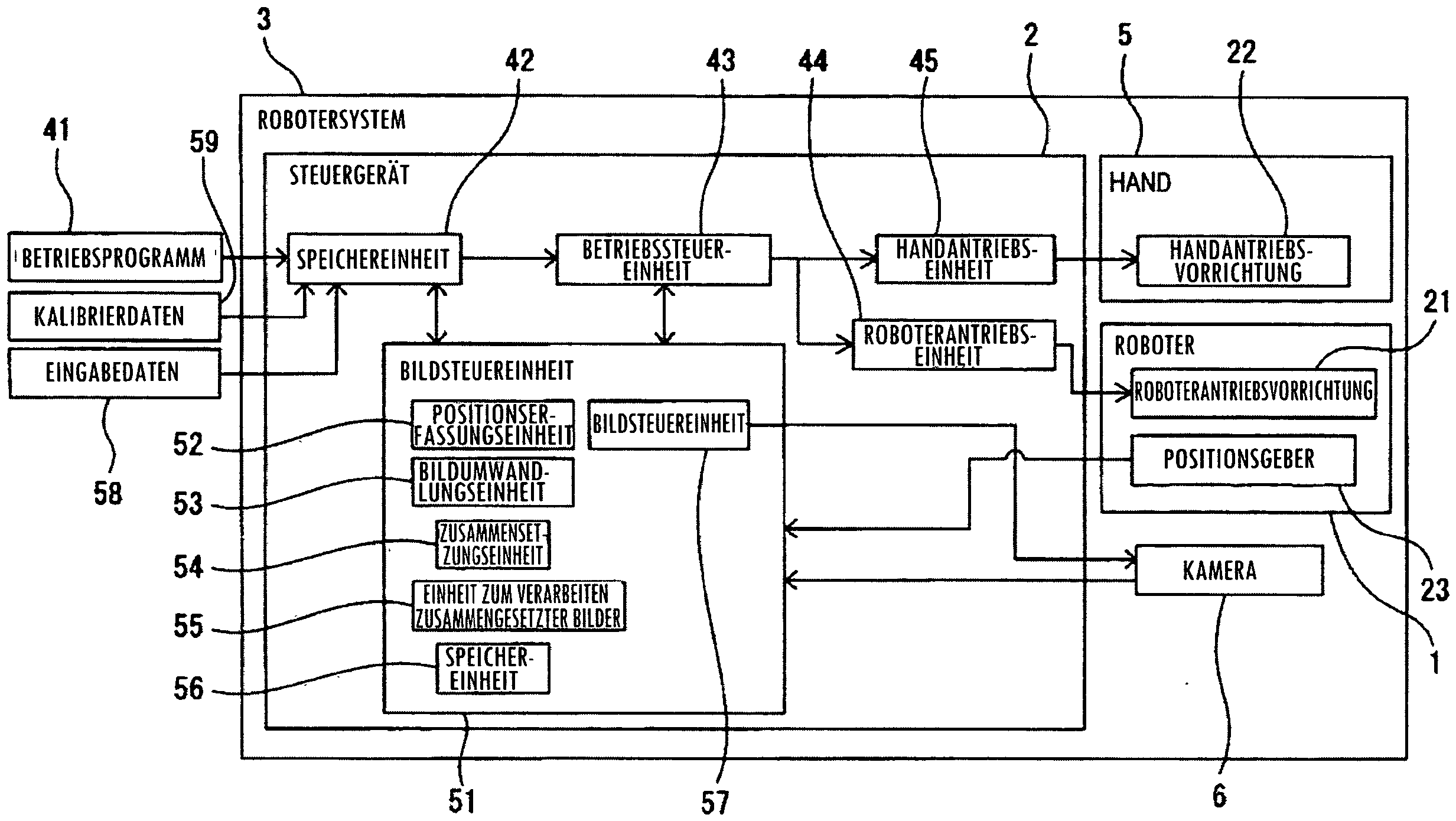
Das Steuergerät 2 steuert den Roboter 1 und die Hand 5. Das Steuergerät 2 umfasst eine arithmetische Verarbeitungsvorrichtung (Rechner) mit einer CPU (Central Processing Unit) und ein RAM (Random Access memory) und ein ROM (Read Only Memory) u. Ä., die über einen Bus mit der CPU verbunden sind. Der Roboter 1 wird gemäß Betätigungsbefehlen vom Steuergerät 2 angetrieben. Der Roboter 1 transportiert das Werkstück 38 automatisch gemäß einem Betriebsprogramm 41. Die Roboterantriebsvorrichtung 21 und die Handantriebsvorrichtung 22 werden vom Steuergerät 2 gesteuert.The controller 2 controls the robot 1 and the hand 5. The controller 2 includes an arithmetic processing device (computer) having a CPU (Central Processing Unit) and a RAM (Random Access Memory) and a ROM (Read Only Memory) and the like connected to the CPU via a bus. The robot 1 is driven according to operation commands from the controller 2. The robot 1 automatically transports the workpiece 38 according to an operation program 41. The robot drive device 21 and the hand drive device 22 are controlled by the controller 2.

Das Betriebsprogramm 41, das vorab zum Betreiben des Roboters 1 vorbereitet wurde, wird am Steuergerät 2 eingegeben. Das Betriebsprogramm 41 wird in einer Speichereinheit 42 gespeichert. Eine Betriebssteuereinheit 43 sendet einen Betätigungsbefehl an eine Roboterantriebseinheit 44 zum Antreiben des Roboters 1 gemäß dem Betriebsprogramm 41. Die Roboterantriebseinheit 44 umfasst eine elektrische Schaltung zum Antrieb von Antriebsmotoren und versorgt die Roboterantriebsvorrichtung 21 mit Strom gemäß Betätigungsbefehlen.The operation program 41 prepared in advance for operating the robot 1 is input to the controller 2. The operation program 41 is stored in a storage unit 42. An operation control unit 43 sends an operation command to a robot drive unit 44 to drive the robot 1 according to the operation program 41. The robot drive unit 44 includes an electric circuit for driving drive motors and supplies the robot drive device 21 with power according to operation commands.

Ferner sendet die Betriebssteuereinheit 43 einen Betätigungsbefehl zum Antreiben der Handantriebsvorrichtung 22 an eine Handantriebseinheit 45. Die Handantriebseinheit 45 umfasst eine elektrische Schaltung zum Antrieb der Pneumatikpumpe u. Ä. und versorgt die Pneumatikpumpe u. Ä. mit Strom gemäß Betätigungsbefehlen.Further, the operation control unit 43 sends an operation command for driving the manual driving device 22 to a manual driving unit 45. The manual driving unit 45 includes an electric circuit for driving the pneumatic pump and the like, and supplies the pneumatic pump and the like with power according to operation commands.

Der Roboter 1 umfasst einen Zustandsgeber zum Erfassen einer Position und einer Ausrichtung des Roboters 1. Der Zustandsgeber gemäß der vorliegenden Ausführungsform umfasst einen Positionsgeber 23, der an einem Antriebsmotor für jede Antriebsachse der Roboterantriebsvorrichtung 21 befestigt ist. Beispielsweise kann der Positionsgeber 23 Drehwinkel zum Zeitpunkt, zu dem der Antriebsmotor der Roboterantriebsvorrichtung 21 angetrieben wird, erfassen. Die Position und die Ausrichtung des Roboters 1 werden von der Ausgabe vom Positionsgeber 23 erfasst. Der Zustandsgeber ist nicht auf den Positionsgeber, der am Antriebsmotor befestigt ist, beschränkt und es kann ein beliebiger Geber verwendet werden, der die Position und die Ausrichtung des Roboters 1 erfassen kann.The robot 1 includes a state sensor for detecting a position and an orientation of the robot 1. The state sensor according to the present embodiment includes a position sensor 23 attached to a drive motor for each drive axis of the robot drive device 21. For example, the position sensor 23 can detect rotation angles at the time the drive motor of the robot drive device 21 is driven. The position and the orientation of the robot 1 are detected from the output from the position sensor 23. The state sensor is not limited to the position sensor attached to the drive motor, and any sensor may be used. which can detect the position and orientation of robot 1.

Ein Referenzkoordinatensystem 71, das sich nicht bewegt, wenn sich die Position und die Ausrichtung des Roboters 1 ändern, ist im Robotersystem 3 eingerichtet. Im in 1 dargestellten Beispiel ist der Ursprung des Referenzkoordinatensystems 71 in der Basis 14 des Roboters 1 angeordnet. Das Referenzkoordinatensystem 71 wird ebenfalls als Weltkoordinatensystem bezeichnet. Im Referenzkoordinatensystem 71 ist die Position des Ursprungs festgelegt und die Richtung von jeder Koordinatenachse ist ebenfalls festgelegt. Weder die Position noch die Ausrichtung des Referenzkoordinatensystems 71 ändern sich, selbst wenn sich die Position und die Ausrichtung des Roboters 1 ändern. Das Referenzkoordinatensystem 71 weist eine X-Achse, eine Y-Achse und eine Z-Achse auf, die jeweils als eine Koordinatenachse dienen und senkrecht zueinander sind. Ferner ist eine W-Achse als eine Koordinatenachse um die X-Achse festgelegt. Eine P-Achse ist als eine Koordinatenachse um die Y-Achse festgelegt. Eine R-Achse ist als eine Koordinatenachse um die Z-Achse festgelegt.A reference coordinate system 71, which does not move when the position and orientation of the robot 1 change, is set up in the robot system 3. In 1 In the example shown, the origin of the reference coordinate system 71 is located in the base 14 of the robot 1. The reference coordinate system 71 is also called a world coordinate system. In the reference coordinate system 71, the position of the origin is fixed, and the direction of each coordinate axis is also fixed. Neither the position nor the orientation of the reference coordinate system 71 changes even if the position and orientation of the robot 1 change. The reference coordinate system 71 has an X-axis, a Y-axis, and a Z-axis, each serving as a coordinate axis and being perpendicular to each other. Further, a W-axis is set as a coordinate axis around the X-axis. A P-axis is set as a coordinate axis around the Y-axis. An R-axis is set as a coordinate axis around the Z-axis.

Ferner ist ein Flanschkoordinatensystem 72 auf einer Fläche der Oberfläche des Flansches 16, auf dem die Hand 5 befestigt ist, festgelegt. Das Flanschkoordinatensystem 72 wird ebenfalls als Handenden-Koordinatensystem bezeichnet. Der Ursprung des Flanschkoordinatensystems 72 ist auf der Drehachse des Flanschs 16 angeordnet. Das Flanschkoordinatensystem 72 weist eine X-Achse, eine Y-Achse und eine Z-Achse auf, die senkrecht zueinander sind. Ferner weist das Flanschkoordinatensystem 72 eine W-achse um die X-Achse, eine P-Achse um die Y-Achse und eine R-Achse um die Z-Achse auf. Wenn sich die Position und die Ausrichtung des Roboters 1 ändern, ändern sich ebenfalls die Position des Ursprungs des Flanschkoordinatensystems 72 und die Ausrichtung des Koordinatensystems in Verbindung mit dem Flansch 16. Durch Umwandeln von Koordinatenwerten des Flanschkoordinatensystems 72 durch eine Matrix können Koordinatenwerte des Referenzkoordinatensystems 71 berechnet werden. Ferner können durch Umwandeln von Koordinatenwerten des Referenzkoordinatensystems 71 durch eine Matrix Koordinatenwerte des Flanschkoordinatensystems 72 berechnet werden.Further, a flange coordinate system 72 is set on a face of the surface of the flange 16 on which the hand 5 is attached. The flange coordinate system 72 is also called a hand end coordinate system. The origin of the flange coordinate system 72 is located on the rotation axis of the flange 16. The flange coordinate system 72 has an X-axis, a Y-axis and a Z-axis which are perpendicular to each other. Further, the flange coordinate system 72 has a W-axis around the X-axis, a P-axis around the Y-axis and an R-axis around the Z-axis. When the position and orientation of the robot 1 change, the position of the origin of the flange coordinate system 72 and the orientation of the coordinate system in connection with the flange 16 also change. By converting coordinate values of the flange coordinate system 72 by a matrix, coordinate values of the reference coordinate system 71 can be calculated. Furthermore, by converting coordinate values of the reference coordinate system 71 by a matrix, coordinate values of the flange coordinate system 72 can be calculated.

Das Robotersystem 3 gemäß der vorliegenden Ausführungsform umfasst eine Bildgebungsvorrichtung, die ein Erfassen und/oder Prüfen des Werkstücks 38 durchführt. Beim ersten Robotersystem 3 wird die Position des Werkstücks 38 auf dem Montagetisch 95 erfasst, bevor die Hand 5 das Werkstück 38 greift. Die Bildgebungsvorrichtung umfasst die Kamera 6, die als ein Sichtsensor dient, der ein erstes Bild des Werkstücks 38 erfasst. Das erste Bild ist ein Bild, das durch aktuelles Erfassen des Bildes des Werkstücks 38 unter Verwendung der Kamera 6 ermittelt wird. Die Kamera 6 gemäß der vorliegenden Ausführungsform ist eine Kamera, die ein zweidimensionales Bild erfasst. Die Kamera 6 wird vom Roboter 1 gestützt. Die Kamera 6 ist durch ein Stützelement am Handgelenk 15 befestigt. Die Kamera 6 ist am Roboter 1 befestigt, so dass das Bild des Werkstücks 38 erfasst werden kann, wenn der Roboter 1 seine Position und Ausrichtung ändert.The robot system 3 according to the present embodiment includes an imaging device that performs detection and/or inspection of the workpiece 38. In the first robot system 3, the position of the workpiece 38 on the assembly table 95 is detected before the hand 5 grips the workpiece 38. The imaging device includes the camera 6 serving as a vision sensor that captures a first image of the workpiece 38. The first image is an image obtained by actually capturing the image of the workpiece 38 using the camera 6. The camera 6 according to the present embodiment is a camera that captures a two-dimensional image. The camera 6 is supported by the robot 1. The camera 6 is attached to the wrist 15 through a support member. The camera 6 is attached to the robot 1 so that the image of the workpiece 38 can be captured when the robot 1 changes its position and orientation.

Die Bildgebungsvorrichtung gemäß der vorliegenden Ausführungsform umfasst eine Bewegungsvorrichtung, die das Werkstück 38 und die Kamera 6 so bewegt, dass sich eine relative Position des Werkstücks bzw. der Kamera in Bezug aufeinander ändert. Beim Robotersystem 3 dient der Roboter 1 als Bewegungsvorrichtung und die Kamera 6 ist am Handende des Roboters 1 montiert. Wenn sich die Position und die Ausrichtung des Roboters 1 ändern, ändern sich ebenfalls die Position und die Ausrichtung der Kamera 6. Ferner dient der Montagetisch 95 als ein Fixierungsteil zum Fixieren des Werkstücks 38.The imaging device according to the present embodiment includes a moving device that moves the workpiece 38 and the camera 6 so that a relative position of the workpiece and the camera with respect to each other changes. In the robot system 3, the robot 1 serves as a moving device, and the camera 6 is mounted on the hand end of the robot 1. When the position and orientation of the robot 1 change, the position and orientation of the camera 6 also change. Further, the mounting table 95 serves as a fixing part for fixing the workpiece 38.

Die Bildgebungsvorrichtung umfasst eine Bildverarbeitungsvorrichtung, die das vom Sichtsensor erfasste erste Bild verarbeitet. Beim Robotersystem 3 gemäß der vorliegenden Ausführungsform dient das Steuergerät 2 als Bildverarbeitungsvorrichtung. Das Steuergerät 2 umfasst eine Bildsteuereinheit 51. Die Bildsteuereinheit 51 umfasst eine Bildgebungssteuereinheit 57, die an die Kamera 6 einen Befehl zum Erfassen eines Bildes sendet. Die Bildsteuereinheit 51 weist eine Funktion zum Verarbeiten eines von der Kamera 6 erfassten ersten Bildes auf. Die Bildsteuereinheit 51 umfasst eine Speichereinheit 56, die Informationen zur Bildgebung des Werkstücks 38 speichert.The imaging device includes an image processing device that processes the first image captured by the vision sensor. In the robot system 3 according to the present embodiment, the controller 2 serves as an image processing device. The controller 2 includes an image control unit 51. The image control unit 51 includes an imaging control unit 57 that sends a command to the camera 6 to capture an image. The image control unit 51 has a function of processing a first image captured by the camera 6. The image control unit 51 includes a storage unit 56 that stores information for imaging the workpiece 38.

3 zeigt eine Seitenansicht des Roboters zur Darstellung der Bewegung der Kamera, wenn das Bild des Werkstücks erfasst wird. Wenn sich die Position und die Ausrichtung des Roboters 1 ändern, ändern sich die Position und die Ausrichtung der Kamera 6. Die Kamera 6 kann an einer beliebigen Position angeordnet sein, an der das Bild des Werkstücks 38 erfasst werden kann. Beim ersten Robotersystem 3 werden die Bilder des Werkstücks 38 an einer Mehrzahl von vorgegebenen Positionen der Kamera 6 erfasst. Die Kamera 6 erfasst eine Mehrzahl von ersten Bildern an verschiedenen Bildgebungspositionen. Beim in 3 dargestellten Beispiel erfasst die Kamera 6 das Bild des Werkstücks 38 an der Position P6a. Anschließend, nachdem der Roboter 1 die Kamera 6 von der Position P6a zur Position P6B bewegt wie durch den Pfeil 91 angegeben, erfasst die Kamera 6 das Bild des Werkstücks 38. 3 shows a side view of the robot to illustrate the movement of the camera when the image of the workpiece is captured. When the position and orientation of the robot 1 change, the position and orientation of the camera 6 change. The camera 6 can be arranged at any position where the image of the workpiece 38 can be captured. In the first robot system 3, the images of the workpiece 38 are captured at a plurality of predetermined positions of the camera 6. The camera 6 captures a plurality of first images at different imaging positions. In the first 3 In the example shown, the camera 6 captures the image of the workpiece 38 at the position P6a. Then, after the robot 1 moves the camera 6 from the position P6a to the position P6B as indicated by the arrow 91, the camera 6 captures the image of the workpiece 38.

Ferner, nachdem der Roboter 1 die Kamera 6 zur Position P6c bewegt wie durch den Pfeil 92 angegeben, erfasst die Kamera 6 das Bild des Werkstücks 38. Auf diese Weise wird eine Mehrzahl von ersten Bildern des Werkstücks 38 erfasst, so dass sich eine Mehrzahl von relativen Positionen der Kamera 6 in Bezug auf das Werkstück 38 voneinander unterscheidet. Die Mehrzahl der Positionen P6a, P6b, P6c der Kamera 6, an der die ersten Bilder erfasst werden, sind vorgegeben. Ferner sind die Positionen und die Ausrichtungen des Roboters 1, die den Positionen P6a, P6b, P6c entsprechen, im Betriebsprogramm 41 festgelegt. Die Kamera 6 erfasst eine Mehrzahl von ersten Bildern an einer Mehrzahl von vorgegebenen Positionen und Ausrichtungen des Roboters 1.Further, after the robot 1 moves the camera 6 to the position P6c as indicated by the arrow 92, the camera 6 captures the image of the workpiece 38. In this way, a plurality of first images of the workpiece 38 are captured so that a plurality of relative positions of the camera 6 with respect to the workpiece 38 are different from each other. The plurality of positions P6a, P6b, P6c of the camera 6 at which the first images are captured are predetermined. Further, the positions and the orientations of the robot 1 corresponding to the positions P6a, P6b, P6c are set in the operation program 41. The camera 6 captures a plurality of first images at a plurality of predetermined positions and orientations of the robot 1.

Die Kamera 6 kann eine Mehrzahl von ersten Bildern erfassen, ohne die Mehrzahl der Positionen und Ausrichtungen des Roboters 1 vorzugeben. Beispielsweise kann die Ausgangsposition der Kamera 6 als die Position P6a festgelegt werden und die Position der Kamera 6 nach dem Bewegen kann als Position P6b festgelegt werden. Die Bilder des Werkstücks 38 können in konstanten Zeitintervallen während der Zeit, in der die Kamera 6 von der Position P6a zur Position P6b bewegt wird, während der Roboter 1 angetrieben wird, erfasst werden. In solch einem Fall ist es erforderlich, dass die Positionen und die Ausrichtungen des Roboters 1 zum Zeitpunkt, zu dem die Kamera 6 die ersten Bilder erfasst, mit den entsprechenden ersten Bildern verknüpft werden, um einen Satz aus erstem Bild und der Position und der Ausrichtung des Roboters 1 zu bilden, und dieser Satz wird in der Speichereinheit 56 gespeichert. Zwar werden hier die Position und die Ausrichtung des Roboters 1 gespeichert; aber die Ausführung ist nicht hierauf beschränkt. Die Position und die Ausrichtung der Kamera 6 oder eine andere Position, die auf der Basis der Position und der Ausrichtung des Roboters 1 berechnet werden können, kann in der Speichereinheit 56 gespeichert werden.The camera 6 may capture a plurality of first images without specifying the plurality of positions and attitudes of the robot 1. For example, the initial position of the camera 6 may be set as the position P6a, and the position of the camera 6 after moving may be set as the position P6b. The images of the workpiece 38 may be captured at constant time intervals during the time the camera 6 is moved from the position P6a to the position P6b while the robot 1 is driven. In such a case, it is necessary that the positions and attitudes of the robot 1 at the time the camera 6 captures the first images are linked to the corresponding first images to form a set of the first image and the position and attitude of the robot 1, and this set is stored in the storage unit 56. Although the position and attitude of the robot 1 are stored here, the embodiment is not limited to this. The position and orientation of the camera 6 or another position that can be calculated based on the position and orientation of the robot 1 can be stored in the storage unit 56.

4 zeigt eine Seitenansicht zum Erläutern der Positionen der Kamera, an denen die Bilder des Werkstücks erfasst werden, und der Position der Kamera, die einem zum Erfassen des Werkstücks verwendeten Bild entspricht. In der vorliegenden Ausführungsform wird eine zum Erfassen des Werkstücks 38 verwendete Erfassungsfläche 75 vorab am Werkstück 38 definiert. Die Bildsteuereinheit 51 erfasst die Position des Werkstücks 38 auf der Erfassungsfläche 75. Die Erfassungsfläche 75 kann so festgelegt werden, dass sie sich entlang der Fläche eines Teils des Werkstücks 38 erstreckt. Insbesondere kann die Erfassungsfläche 75 so festgelegt werden, dass sie die Fläche eines Teils des Werkstücks 38 umfasst. Die Bildsteuereinheit 51 verwendet auf dieser Fläche gezeigte Merkmalspunkte oder Helligkeitswerte, um eine Erfassung und/oder Prüfung des Werkstücks 38 durchzuführen. Die Erfassungsfläche 75 kann im Referenzkoordinatensystem 71 ausgedrückt werden. Informationen über die Erfassungsfläche 75 werden in der Speichereinheit 56 gespeichert. Es können verschiedene Abschnitte für die Merkmalspunkte verwendet werden und bei der vorliegenden Ausführungsform werden Randpunkte als Merkmalspunkte verwendet. Die Randpunkte sind Punkte, an denen der Stärkegradient im Bild groß ist, und können zum Ermitteln der Form der Kontur des Werkstücks 38 verwendet werden. Das Verfahren zum Extrahieren von Randpunkten entspricht dem Stand der Technik und daher wird auf eine Erläuterung von diesem verzichtet. 4 shows a side view for explaining the positions of the camera at which the images of the workpiece are captured and the position of the camera corresponding to an image used to capture the workpiece. In the present embodiment, a detection area 75 used to capture the workpiece 38 is defined in advance on the workpiece 38. The image control unit 51 captures the position of the workpiece 38 on the detection area 75. The detection area 75 may be set to extend along the surface of a part of the workpiece 38. Specifically, the detection area 75 may be set to include the surface of a part of the workpiece 38. The image control unit 51 uses feature points or brightness values shown on this area to perform detection and/or inspection of the workpiece 38. The detection area 75 may be expressed in the reference coordinate system 71. Information about the detection area 75 is stored in the storage unit 56. Various portions may be used for the feature points, and in the present embodiment, edge points are used as the feature points. The edge points are points where the intensity gradient in the image is large, and can be used to determine the shape of the contour of the workpiece 38. The method of extracting edge points is in accordance with the prior art, and therefore, explanation thereof is omitted.

Die Positionen, an denen die Kamera 6 erste Bilder erfasst, sind die Positionen P6a, P6b, P6c. Wiederum wird eine Erfassungsposition P6D, die eine Position der Kamera 6 ist, an der das Werkstück 38 erfasst wird, vorab ermittelt. Die Erfassungsposition P6D ist eine von einem Bediener festgelegte imaginäre Position. Die Erfassungsposition P6D kann auf eine beliebige Position festgelegt werden, an der die Kamera 6 das Bild des Werkstücks 38 erfassen kann. Ferner werden die Position und Ausrichtung des Roboters 1, die zum Anordnen der Kamera 6 an der Erfassungsposition 6d verwendet werden, als Sollposition der Bewegungsvorrichtung vorgegeben. Die Position und die Ausrichtung des Roboters 1 werden in der Speichereinheit 56 gespeichert. Informationen über die Erfassungsposition P6d der Kamera 6 können durch Verwenden des Referenzkoordinatensystems 71 in der Speichereinheit 56 gespeichert werden. Die Erfassungsposition P6d ist nicht auf eine imaginäre Position beschränkt und es kann eine Position aus Positionen der Kamera 6 ausgewählt werden, an denen eine Mehrzahl von ersten Bildern erfasst wird.The positions at which the camera 6 captures first images are positions P6a, P6b, P6c. Again, a detection position P6D, which is a position of the camera 6 at which the workpiece 38 is captured, is determined in advance. The detection position P6D is an imaginary position set by an operator. The detection position P6D can be set to any position at which the camera 6 can capture the image of the workpiece 38. Further, the position and orientation of the robot 1 used to arrange the camera 6 at the detection position 6d are set as a target position of the moving device. The position and orientation of the robot 1 are stored in the storage unit 56. Information about the detection position P6d of the camera 6 can be stored in the storage unit 56 by using the reference coordinate system 71. The detection position P6d is not limited to an imaginary position, and a position may be selected from positions of the camera 6 at which a plurality of first images are detected.

5 zeigt eine schematische Ansicht zum Erläutern eines in der vorliegenden Ausführungsform erfassten erstens Bildes und von Verarbeitungen des ersten Bildes. Gemäß 2, 4 und 5 erfasst die Kamera 6 erste Bilder 61a, 61b, 61c an den Positionen P6a, P6b, P6c. Das erste Bild 61a ist ein von der Kamera 6 an der Position P6a erfasstes Bild, das erste Bild 61b ist ein von der Kamera 6 an der Position P6b erfasstes Bild und das erste Bild 61c ist ein von der Kamera 6 an der Position P6c erfasstes Bild. Anschließend wandelt die Bildsteuereinheit 51 die ersten Bilder 61a, 61b, 61c jeweils in zweite Bilder 62a, 62b, 62c um, wenn sie an der Erfassungsposition P6d erfasst werden, wie durch den Pfeil 93 angegeben. 5 shows a schematic view for explaining a first image acquired in the present embodiment and processings of the first image. According to 2 , 4 and 5 the camera 6 captures first images 61a, 61b, 61c at the positions P6a, P6b, P6c. The first image 61a is an image captured by the camera 6 at the position P6a, the first image 61b is an image captured by the camera 6 at the position P6b, and the first image 61c is an image captured by the camera 6 at the position P6c. Then, the image control unit 51 converts the first images 61a, 61b, 61c into second images 62a, 62b, 62c, respectively, when they are captured at the capture position P6d, as indicated by the arrow 93.

Die zweiten Bilder 62a, 62b, 62c sind unter der Annahme, dass das Werkstück 38, das in den von der Kamera 6 erfassten ersten Bilder 61a, 61b, 61c dargestellt ist, von der Erfassungsposition P6d erfasst wird, ermittelte Bilder. Das zweite Bild 62a ist ein durch Umwandeln des erstens Bildes 61a in dieses ermitteltes Bild, das zweite Bild 62b ist ein durch Umwandeln des ersten Bildes 61b in dieses ermitteltes Bild und das zweite Bild 62c ist ein durch Umwandeln des ersten Bildes 61c in dieses ermitteltes Bild.The second images 62a, 62b, 62c are images obtained under the assumption that the workpiece 38 shown in the first images 61a, 61b, 61c captured by the camera 6 is captured from the capture position P6d. The second image 62a is an image obtained by converting the first image 61a into this, the second image 62b is an image obtained by converting the first image 61b into this, and the second image 62c is an image obtained by converting the first image 61c into this.

Anschließend setzt die Bildsteuereinheit 51 die Mehrzahl der zweiten Bilder 62a, 62b, 62c zusammen, um ein zusammengesetztes Bild 63 zu erzeugen wie durch den Pfeil 94 angegeben. Einige Randpunkte des Werkstücks 38 können in den ersten Bildern 61a, 61b, 61c, die aktuell erfasst wurden, unklar sein. Beispielsweise kann die Linie der Kontur des Werkstücks 38 aufgrund des Auftretens einer Lichthofbildung an einem Abschnitt 65 des ersten Bildes 61b, das aktuell erfasst wurde, unklar sein. Auch in solch einem Fall kann der unklare Abschnitt durch Erzeugen des zusammengesetzten Bildes 63 ausgeschlossen werden.Then, the image control unit 51 assembles the plurality of second images 62a, 62b, 62c to generate a composite image 63 as indicated by the arrow 94. Some edge points of the workpiece 38 may be unclear in the first images 61a, 61b, 61c that have been currently acquired. For example, the line of the contour of the workpiece 38 may be unclear due to the occurrence of halation at a portion 65 of the first image 61b that has been currently acquired. Also in such a case, the unclear portion can be excluded by generating the composite image 63.

Somit kann die Bildsteuereinheit 51 die Position des Werkstücks 38 genau erfassen. Danach korrigiert die Betriebssteuereinheit 43 die Position und die Ausrichtung des Roboters 1 auf der Basis der Position des Werkstücks 38. Diese Steuerung ermöglicht der Hand 5 das Greifen des Werkstücks 38.Thus, the image control unit 51 can accurately detect the position of the workpiece 38. Then, the operation control unit 43 corrects the position and orientation of the robot 1 based on the position of the workpiece 38. This control enables the hand 5 to grip the workpiece 38.

Nachfolgend ist in Bezug auf 2 bis 5 eine Steuerung der vorliegenden Ausführungsform ausführlich beschrieben. Der Bediener führt vorab eine Kalibrierung der Kamera 6 durch. Es wird angenommen, dass Kalibrierdaten 59 ermittelt werden, um eine Beziehung zwischen einem Kamerakoordinatensystem, das als Basis für die Messverarbeitung durch die Kamera 6 dient, und dem Referenzkoordinatensystem herzustellen. Die Kalibrierdaten 59 werden in der Speichereinheit 42 gespeichert. Die Bildsteuereinheit 51 ermittelt die Kalibrierdaten 59 von der Speichereinheit 42 und speichert diese in der Speichereinheit 56. Die Kalibrierdaten 59 umfassen intrinsische Parameter umfassend Informationen beispielsweise zur Brennweite der Kamera 6 und Verzerrung einer Linse. Ferner umfassen die Kalibrierdaten 59 extrinsische Parameter umfassend eine relative Positionsbeziehung des Flanschkoordinatensystems 72 in Bezug auf das Bildkoordinatensystem 73 im von der Kamera 6 erfassten ersten Bild.The following is with regard to 2 until 5 a control of the present embodiment will be described in detail. The operator performs calibration of the camera 6 in advance. It is assumed that calibration data 59 is acquired to establish a relationship between a camera coordinate system, which serves as a basis for measurement processing by the camera 6, and the reference coordinate system. The calibration data 59 is stored in the storage unit 42. The image control unit 51 acquires the calibration data 59 from the storage unit 42 and stores it in the storage unit 56. The calibration data 59 includes intrinsic parameters including information on, for example, the focal length of the camera 6 and distortion of a lens. Furthermore, the calibration data 59 includes extrinsic parameters including a relative positional relationship of the flange coordinate system 72 with respect to the image coordinate system 73 in the first image captured by the camera 6.

Ferner gibt der Bediener Eingabedaten 58 am Steuergerät 2 ein. Die Eingabedaten 58 werden in der Speichereinheit 42 gespeichert. Die Bildsteuereinheit 51 ermittelt die Eingabedaten 58 von der Speichereinheit 42 und speichert diese in der Speichereinheit 56. Die Eingabedaten 58 umfassen Informationen zur Erfassungsfläche 75. Die Erfassungsfläche 75 kann auf einer ebenen Fläche festgelegt werden.Furthermore, the operator inputs input data 58 on the control unit 2. The input data 58 is stored in the storage unit 42. The image control unit 51 obtains the input data 58 from the storage unit 42 and stores it in the storage unit 56. The input data 58 includes information on the detection area 75. The detection area 75 can be set on a flat surface.

Alternativ kann die Erfassungsfläche 75 eine Kurve umfassen oder kann durch Verbinden einer Mehrzahl von Polygonen miteinander gebildet werden.Alternatively, the detection area 75 may comprise a curve or may be formed by connecting a plurality of polygons together.

Die Erfassungsfläche 75 gemäß der vorliegenden Ausführungsform wird vorab von einem Bediener festgelegt. Die Erfassungsfläche ist nicht auf diesen Modus beschränkt und es kann auch eine vorgegebene Fläche des Werkstücks durch Verwenden eines anderen Sensors gemessen werden und eine Erfassungsfläche wird so festgelegt, dass sie diese vorgegebene Fläche umfasst.The detection area 75 according to the present embodiment is set in advance by an operator. The detection area is not limited to this mode, and a predetermined area of the workpiece may be measured by using another sensor, and a detection area is set to include this predetermined area.

Ferner gibt der Bediener vor, welche Position des Bildes verwendet wird, um ein zusammengesetztes Bild zu erzeugen, das am Ende zu erzeugen ist. Die Eingabedaten 58 umfassen die Position und die Ausrichtung des Roboters 1, um die Kamera 6 an der Erfassungsposition P6d zum Erfassen der Position des Werkstücks 38 anzuordnen. Für ein Bild, das der Erfassungsposition P6d entspricht, können Bedingungen verwendet werden, die sich von Bildgebungsbedingungen unterscheiden, wenn das Bild des Werkstücks 38 aktuell erfasst wird. Beispielsweise können für ein Bild, das der Erfassungsposition P6d entspricht, Werte festgelegt werden, die sich von denen, die verwendet werden, wenn ein Bild aktuell erfasst wird, in Bezug auf Brennweite, Blickwinkel, Pixelzahl, Linsenverzerrung u. Ä. der Kamera unterscheiden. Diese Informationsteile können in den Eingabedaten 58 enthalten sein.Furthermore, the operator specifies which position of the image is used to generate a composite image to be finally generated. The input data 58 includes the position and orientation of the robot 1 to arrange the camera 6 at the detection position P6d for detecting the position of the workpiece 38. For an image corresponding to the detection position P6d, conditions different from imaging conditions when the image of the workpiece 38 is actually detected may be used. For example, for an image corresponding to the detection position P6d, values different from those used when an image is actually detected may be set in terms of the focal length, angle of view, number of pixels, lens distortion, and the like of the camera. These pieces of information may be included in the input data 58.

Die Position und die Ausrichtung des Roboters 1 zum Erfassen des ersten Bildes werden vorab im Betriebsprogramm 41 festgelegt. Gemäß dem Betriebsprogramm 41 ändert die Betriebssteuereinheit 43 die Position und die Ausrichtung des Roboters 1, um das Bild des Werkstücks 38 zu erfassen. Die Bildgebungssteuereinheit 57 sendet an die Kamera 6 einen Befehl zum Erfassen des Bildes des Werkstücks 38, wenn der Roboter 1 die Position und die Ausrichtung erreicht, die vorgegeben wurden. Die Kamera 6 erfasst Bilder des Werkstücks 38 an einer Mehrzahl von vorgegebenen Positionen P6a, P6b, P6c. In 3 werden zwar die ersten Bilder 61a, 61b, 61c an den Positionen P6a, P6b, P6c erfasst; aber die Ausführungsform ist nicht hierauf beschränkt und es können zwei oder mehr erste Bilder von beliebigen Positionen erfasst werden. Für die Position der Kamera 6, die das Bild des Werkstücks 38 erfasst kann eine beliebige Position gewählt werden, an der das Werkstück 38 im Sichtfeld der Kamera 6 liegt. Auf diese Weise werden die Bilder des Werkstücks 38 von einer Mehrzahl von Blickpunkten erfasst.The position and orientation of the robot 1 for capturing the first image are set in advance in the operation program 41. According to the operation program 41, the operation control unit 43 changes the position and orientation of the robot 1 to capture the image of the workpiece 38. The imaging control unit 57 sends a command to the camera 6 to capture the image of the workpiece 38 when the robot 1 reaches the position and orientation that have been specified. The camera 6 captures images of the workpiece 38 at a plurality of specified positions P6a, P6b, P6c. In 3 the first images 61a, 61b, 61c are captured at the positions P6a, P6b, P6c; however, the embodiment is not limited to this and two or more first images can be captured from any positions. Any position at which the workpiece 38 lies in the field of view of the camera 6 can be selected for the position of the camera 6 that captures the image of the workpiece 38. In this way, the images of the workpiece 38 are captured from a plurality of viewpoints.

Im in 3 dargestellten Beispiel wird zwar eine Mehrzahl von Antriebsachsen des Roboters 1 angetrieben; die Ausführungsform ist aber nicht hierauf beschränkt und es kann eine einzelne Antriebsachse betrieben werden, um die Position der Kamera 6 zu ändern. Durch Verwenden dieser Steuerung wird ein Fehler verhindert, der auftritt, wenn der Bestandteil des Roboters 1 an der Antriebsachse in Betrieb ist. Ferner ist, obgleich sich die Richtung der Kamera 6 (Richtung der optischen Achse) im in 3 dargestellten Beispiel ändert, die Ausführungsform nicht hierauf beschränkt und es kann ein paralleles Verschieben der Kamera 6 ohne Ändern der Richtung der Kamera 6 durchgeführt werden.In 3 In the example shown, a plurality of drive axes of the robot 1 are driven; however, the embodiment is not here and a single drive axis can be operated to change the position of the camera 6. By using this control, an error that occurs when the component of the robot 1 on the drive axis is operated is prevented. Furthermore, although the direction of the camera 6 (optical axis direction) in the 3 example shown, the embodiment is not limited to this and a parallel movement of the camera 6 can be carried out without changing the direction of the camera 6.

Die Bildsteuereinheit 51 umfasst eine Positionserfassungseinheit 52, die eine relative Position der Kamera 6 in Bezug auf das Werkstück 38 ermittelt. Die Positionserfassungseinheit 52 ermittelt die Position und die Ausrichtung des Roboters 1, wenn das Bild des Werkstücks 38 erfasst wird. Die Positionserfassungseinheit 52 berechnet die Position der Kamera 6, wenn das Bild des Werkstücks 38 erfasst wird, auf der Basis der Position und der Ausrichtung des Roboters 1 und der Kalibrierdaten 59. Die Speichereinheit 56 speichert eine Mehrzahl der von der Kamera 6 an einer Mehrzahl von Positionen erfassten ersten Bilder. Ferner speichert die Speichereinheit 56 einen Satz aus Position und Ausrichtung des Roboters 1, wenn das erste Bild erfasst wird, und das erste Bild.The image control unit 51 includes a position detection unit 52 that detects a relative position of the camera 6 with respect to the workpiece 38. The position detection unit 52 detects the position and orientation of the robot 1 when the image of the workpiece 38 is detected. The position detection unit 52 calculates the position of the camera 6 when the image of the workpiece 38 is detected based on the position and orientation of the robot 1 and the calibration data 59. The storage unit 56 stores a plurality of the first images detected by the camera 6 at a plurality of positions. Further, the storage unit 56 stores a set of the position and orientation of the robot 1 when the first image is detected and the first image.

Das Bildsteuergerät 51 umfasst eine Bildumwandlungseinheit 53, die eine Mehrzahl der von der Kamera 6 erfassten ersten Bilder 61a, 61b, 61c in eine Mehrzahl der zweiten Bilder 62a, 62b, 62c, wenn angenommen wird, dass die Bilder an der Erfassungsposition P6d erfasst werden, auf der Basis der relativen Position der Kamera 6 in Bezug auf die Erfassungsfläche 75 umwandelt. In diesem Beispiel wandelt die Bildumwandlungseinheit 53 die ersten Bilder 61a, 61b, 61c auf der Basis der Positionen und der Ausrichtungen des Roboters 1 um, wenn die Bilder des Werkstücks 38 erfasst werden, wobei die Position und die Ausrichtung so gespeichert werden, dass sie mit den ersten Bildern 61a, 61b, 61c verknüpft werden. Die Bildumwandlungseinheit 53 führt eine Umwandlung in zweite Bilder 62a, 62b, 62c des Werkstücks 38 durch, von denen jedes ermittelt wird, wenn angenommen wird, dass in den ersten Bildern 61a, 61b, 61c enthaltene Werkstücke 38 jeweils an der Sollposition des Roboters 1 erfasst werden, die der Erfassungsposition P6d entspricht. Die zweiten Bilder 62a, 62b, 62c können als von der gleichen imaginären Position erfasste imaginäre Bilder bezeichnet werden. Nachfolgend ist ein Prozess beschrieben, in dem die ersten Bilder 61a, 61b, 61c, die aktuell in 5 erfasst werden, in ein zweites Bild 62a beim Erfassen an der Erfassungsposition P6d umgewandelt werden.The image control device 51 includes an image conversion unit 53 that converts a plurality of the first images 61a, 61b, 61c captured by the camera 6 into a plurality of the second images 62a, 62b, 62c, assuming that the images are captured at the capture position P6d, based on the relative position of the camera 6 with respect to the capture surface 75. In this example, the image conversion unit 53 converts the first images 61a, 61b, 61c based on the positions and the orientations of the robot 1 when the images of the workpiece 38 are captured, and the position and the orientation are stored so as to be associated with the first images 61a, 61b, 61c. The image conversion unit 53 performs conversion into second images 62a, 62b, 62c of the workpiece 38, each of which is obtained when it is assumed that workpieces 38 included in the first images 61a, 61b, 61c are respectively detected at the target position of the robot 1 corresponding to the detection position P6d. The second images 62a, 62b, 62c may be referred to as imaginary images detected from the same imaginary position. A process in which the first images 61a, 61b, 61c currently in 5 captured are converted into a second image 62a when captured at the capture position P6d.

6 zeigt eine Seitenansicht zum Erläutern der Sichtlinie der Kamera, wenn das erste Bild aktuell erfasst wird, und die Sichtlinie der an der Erfassungsposition angeordneten Kamera. 6 zeigt die an der Position P6c angeordnete Kamera 6, an der die Bildgebung aktuell durchgeführt wird, und die an der Erfassungsposition P6d angeordnete Kamera 6. Es können Bildgebungsflächen 76c, 76d im Blickwinkel der Kamera 6 festgelegt werden. Die Bildgebungsflächen 76c, 76d simulieren jeweils eine Fläche eines Bildsensors, etwa eines CCD-(Charge-Coupled-Device-)Sensors und eines CMOS-(Complementary-Metal-Oxide-Semiconductor-)Sensors, die in der Kamera 6 angeordnet sind. 6 shows a side view to explain the line of sight of the camera when the first image is currently captured and the line of sight of the camera located at the capture position. 6 shows the camera 6 arranged at the position P6c at which the imaging is currently performed and the camera 6 arranged at the capture position P6d. Imaging areas 76c, 76d can be defined in the angle of view of the camera 6. The imaging areas 76c, 76d each simulate an area of an image sensor, such as a CCD (charge-coupled device) sensor and a CMOS (complementary metal oxide semiconductor) sensor, which are arranged in the camera 6.

Wie im ersten Bild 61c in 5 dargestellt kann ein Bildkoordinatensystem 73 im von der Kamera 6 erfassten Bild festgelegt werden. Das Bildkoordinatensystem 73 ist ein zweidimensionales Koordinatensystem im erfassten Bild, wobei eine vorgegebene Position der Ursprung von diesem ist. Das Bildkoordinatensystem 73 weist eine X-Achse und eine Y-Achse auf, die senkrecht zueinander sind. Eine Position im Bild kann durch Verwenden des Koordinatenwerts des Bildkoordinatensystems 73 spezifiziert werden. Ferner kann das Bildkoordinatensystem 73 auf den Bildgebungsflächen 76c, 76d festgelegt werden.As in the first picture 61c in 5 As shown, an image coordinate system 73 can be set in the image captured by the camera 6. The image coordinate system 73 is a two-dimensional coordinate system in the captured image, with a predetermined position being the origin thereof. The image coordinate system 73 has an X-axis and a Y-axis that are perpendicular to each other. A position in the image can be specified by using the coordinate value of the image coordinate system 73. Further, the image coordinate system 73 can be set on the imaging surfaces 76c, 76d.

Wenn die Kalibrierdaten 59 auf der Kamera 6 ermittelt wurden und ein dreidimensionaler Punkt (nachfolgend als Betrachtungspunkt bezeichnet) im Referenzkoordinatensystem 71 vorgegeben wurde, kann die Position des dreidimensionalen Punkt auf dem Bild, das heißt des zweidimensionalen Punkts im Bildkoordinatensystem 73, berechnet werden. Ferner kann, wenn ein zweidimensionaler Punkt, der als ein Bild an einem vorgegebenen Betrachtungspunkt dient, im Bildkoordinatensystem 73 vorgegeben ist, die Sichtlinie (dreidimensionale gerade Linie, die durch den Betrachtungspunkt und den Brennpunkt der Kamera 6 läuft) im Referenzkoordinatensystem 71 berechnet werden. Wenn ein Punkt im ersten Bild 61c ausgewählt wird, kann die Kamera 6 eine Sichtlinie 77c entsprechend dem einen Punkt und sich von der Kamera 6 erstreckend berechnet werden. Die Sichtlinie 77C kann durch Verwenden des Flanschkoordinatensystems 72 ausgedrückt werden.When the calibration data 59 has been acquired on the camera 6 and a three-dimensional point (hereinafter referred to as a viewpoint) has been specified in the reference coordinate system 71, the position of the three-dimensional point on the image, that is, the two-dimensional point in the image coordinate system 73, can be calculated. Further, when a two-dimensional point serving as an image at a specified viewpoint is specified in the image coordinate system 73, the line of sight (three-dimensional straight line passing through the viewpoint and the focal point of the camera 6) can be calculated in the reference coordinate system 71. When a point in the first image 61c is selected, the camera 6 can calculate a line of sight 77c corresponding to the one point and extending from the camera 6. The line of sight 77C can be expressed by using the flange coordinate system 72.

Das heißt auf der Basis eines beliebigen Punkts im Bildkoordinatensystem 73 kann die Sichtlinie 77c der Kamera 6 im Flanschkoordinatensystem 72 ermittelt werden. Ferner können auf der Basis der Position und Ausrichtung des Roboters 1 die Position des Ursprungs des Flanschkoordinatensystems 72 und die Ausrichtung des Flanschkoordinatensystems 72 im Referenzkoordinatensystem 71 ermittelt werden. Somit kann die im Flanschkoordinatensystem 72 ausgedrückte Sichtlinie 77c in die im Referenzkoordinatensystem 71 ausgedrückte Sichtlinie 77C umgewandelt werden.That is, based on any point in the image coordinate system 73, the line of sight 77c of the camera 6 in the flange coordinate system 72 can be determined. Furthermore, based on the position and orientation of the robot 1, the position of the origin of the flange coordinate system 72 and the orientation of the flange coordinate system 72 in the reference coordinate system 71 can be determined. Thus, the line of sight 77c expressed in the flange coordinate system 72 can be converted into the line of sight 77c expressed in the reference coordinate system 71. coordinate system 71 expressed line of sight 77C.

Wenn hingegen ein Punkt im Referenzkoordinatensystem 71 festgelegt wird, kann die Sichtlinie 77c im Referenzkoordinatensystem 71 berechnet werden. Ferner kann auf der Basis der Sichtlinie 77c im Referenzkoordinatensystem 71 eine Position des entsprechenden Punkts im Bildkoordinatensystem 73 berechnet werden.On the other hand, when a point is specified in the reference coordinate system 71, the line of sight 77c in the reference coordinate system 71 can be calculated. Furthermore, based on the line of sight 77c in the reference coordinate system 71, a position of the corresponding point in the image coordinate system 73 can be calculated.

Nachfolgend sind in Bezug auf 4 bis 6 als Beispiel ein erstes Bild 61c entsprechend der Position P6c und ein zweites Bild 62c nach der Umwandlung beschrieben. Die Bildumwandlungseinheit 53 wählt den Mittelpunkt in einem beliebigen Pixel im zweiten Bild 62c aus, bei dem angenommen wird, das es von der an der Erfassungsposition P6d angeordneten Kamera 6 erfasst wird. Beispielsweise wählt die Bildumwandlungseinheit 53 einen Punkt 64b aus, welcher der Mittelpunkt in einem Pixel ist. Die Bildumwandlungseinheit 53 berechnet die im Flanschkoordinatensystem 72 ausgedrückte Sichtlinie 77d auf der Basis der Position des Punkts 64b im Bildkoordinatensystem 73. Ferner berechnet die Bildumwandlungseinheit 53 die im Referenzkoordinatensystem 71 ausgedrückte Sichtlinie 77d.The following are in relation to 4 to 6 For example, a first image 61c corresponding to the position P6c and a second image 62c after conversion are described. The image conversion unit 53 selects the center point in any pixel in the second image 62c which is assumed to be captured by the camera 6 arranged at the capture position P6d. For example, the image conversion unit 53 selects a point 64b which is the center point in a pixel. The image conversion unit 53 calculates the line of sight 77d expressed in the flange coordinate system 72 based on the position of the point 64b in the image coordinate system 73. Further, the image conversion unit 53 calculates the line of sight 77d expressed in the reference coordinate system 71.

Die Bildumwandlungseinheit 53 berechnet einen Schnittpunkt 78 zwischen der Sichtlinie 77d und der Erfassungsfläche 75. Die Position dieses Schnittpunkts 78 kann im Referenzkoordinatensystem 71 ausgedrückt werden. Anschließend berechnet die Bildumwandlungseinheit 53 die durch den Schnittpunkt 78 laufende Sichtlinie 77c in Verbindung mit der an der Position P6c angeordneten Kamera 6, an der die Bildgebung aktuell durchgeführt wird. Die Bildumwandlungseinheit 53 ändert die im Referenzkoordinatensystem 71 ausgedrückte Sichtlinie 77c in die im Flanschkoordinatensystem 72 ausgedrückte Sichtlinie 77c um. Ferner berechnet die Bildumwandlungseinheit 53 die Position im Bildkoordinatensystem 73 auf der Bildgebungsfläche 76c, an die Bildgebung aktuell durchgeführt wird, auf der Basis der Sichtlinie 77c. Auf diese Weise kann die Position des Punkts 64a im ersten Bild 61c berechnet werden.The image conversion unit 53 calculates an intersection point 78 between the line of sight 77d and the detection surface 75. The position of this intersection point 78 can be expressed in the reference coordinate system 71. Then, the image conversion unit 53 calculates the line of sight 77c passing through the intersection point 78 in connection with the camera 6 arranged at the position P6c where imaging is currently performed. The image conversion unit 53 changes the line of sight 77c expressed in the reference coordinate system 71 into the line of sight 77c expressed in the flange coordinate system 72. Further, the image conversion unit 53 calculates the position in the image coordinate system 73 on the imaging surface 76c where imaging is currently performed based on the line of sight 77c. In this way, the position of the point 64a in the first image 61c can be calculated.

7 zeigt eine vergrößerte Ansicht zum Darstellen eines ersten Bildes, das aktuell erfasst wird. 7 zeigt Pixel 85a, 85b, 85c in der Nachbarschaft des Punkts 64a, der dem Punkt 64b im zweiten Bild 62c entspricht. Die Position des Punkts 64a dient als entsprechende Position, die dem Mittelpunkt 64b des Pixels im zweiten Bild 62c an der Erfassungsposition P6d entspricht. Der Punkt 64a ist im Pixel 85a umfassend den Mittelpunkt 81a angeordnet. Somit kann die Bildumwandlungseinheit 53 einen Wert eines Pixels, von dem die Mitte der Punkts 64b im zweiten Bild 62c ist, auf einen Pixelwert des Pixels 85a im ersten Bild 61c festlegen. Der Wert des Pixels stellt einen Wert betreffend Leuchtdichte oder Farbe des Pixels dar oder er kann gegebenenfalls die Helligkeit verwenden. 7 shows a zoomed view to show a first image that is currently being captured. 7 shows pixels 85a, 85b, 85c in the vicinity of the point 64a corresponding to the point 64b in the second image 62c. The position of the point 64a serves as a corresponding position corresponding to the center 64b of the pixel in the second image 62c at the detection position P6d. The point 64a is located in the pixel 85a including the center 81a. Thus, the image conversion unit 53 can set a value of a pixel, the center of which is the point 64b in the second image 62c, to a pixel value of the pixel 85a in the first image 61c. The value of the pixel represents a value related to luminance or color of the pixel, or it may use brightness as appropriate.

Die Bildumwandlungseinheit 53 führt die Berechnung des Pixelwerts im zweiten Bild 62c für alle im zweiten Bild 62c enthaltene Pixel durch. Durch Verwenden dieser Steuerung kann die Bildumwandlungseinheit 53 das zweite Bild 62c erzeugen.The image conversion unit 53 performs the calculation of the pixel value in the second image 62c for all pixels included in the second image 62c. By using this control, the image conversion unit 53 can generate the second image 62c.

Wenn eine Position im ersten Bild 61c, die einer Position im zweiten Bild 62c entspricht, außerhalb des Bereichs des ersten Bildes 61c liegt, kann ein vorgegebener Wert für den Wert des Pixels im zweiten Bild 62c festgelegt werden. Im Beispiel des zweiten Bildes 62c in 5 wird, wenn kein entsprechendes Pixel im ersten Bild 61c, das von der Kamera 6 erfasst wird, vorhanden ist, die Helligkeit des Pixels im zweiten Bild 62c auf Null festgelegt. Das heißt der Pixelwert wird so festgelegt, dass er im zweiten Bild 62c schwarz ist.If a position in the first image 61c that corresponds to a position in the second image 62c is outside the range of the first image 61c, a predetermined value can be set for the value of the pixel in the second image 62c. In the example of the second image 62c in 5 if there is no corresponding pixel in the first image 61c captured by the camera 6, the brightness of the pixel in the second image 62c is set to zero. That is, the pixel value is set to be black in the second image 62c.

Ferner kann zum genauen Ermitteln des Pixelwerts der Pixelwert des Pixels 85b, 85c in der Nachbarschaft des Pixels 85a umfassend den Punkt 64a im ersten Bild 61c zum Berechnen des Pixelwerts des Pixels im zweiten Bild 62c verwendet werden. In der vorliegenden Ausführungsform wird eine lineare Interpolation zwischen Pixelwerten einer Mehrzahl von Pixeln 85b, 85c in der Nähe des Punkts 64a und dem Pixelwert des Pixels 85a umfassend den Punkt 64a durchgeführt, wodurch der Wert des Pixels umfassend den Punkt 64b im zweiten Bild 62c berechnet wird.Furthermore, in order to accurately determine the pixel value, the pixel value of the pixel 85b, 85c in the vicinity of the pixel 85a comprising the point 64a in the first image 61c may be used to calculate the pixel value of the pixel in the second image 62c. In the present embodiment, linear interpolation is performed between pixel values of a plurality of pixels 85b, 85c in the vicinity of the point 64a and the pixel value of the pixel 85a comprising the point 64a, thereby calculating the value of the pixel comprising the point 64b in the second image 62c.

Die Bildumwandlungseinheit 53 ermittelt die Position des Punkts 64a in Bezug auf den Mittelpunkt 81a im Pixel 85a. Im in 7 dargestellten Beispiel ist der Punkt 64a rechts vom Mittelpunkt 81a angeordnet und ist niedriger als der Mittelpunkt 81a angeordnet. Die Bildumwandlungseinheit 53 wählt das Pixel 85b und das Pixel 85c als zwei Pixel aus, die am nächsten zum Punkt 64a sind.The image conversion unit 53 determines the position of the point 64a with respect to the center 81a in the pixel 85a. In 7 In the example shown, the point 64a is located to the right of the center point 81a and is located lower than the center point 81a. The image conversion unit 53 selects the pixel 85b and the pixel 85c as two pixels closest to the point 64a.

8 zeigt ein Diagramm zum Erläutern einer angewendeten Interpolation, wenn der Wert des Pixels im zweiten Bild berechnet wird. Die Mittelpunkte 81a, 81b, 81c der entsprechenden Pixel 85a, 85b, 85c werden im Bildkoordinatensystem 73 umfassend die X-Achse und die Y-Achse festgelegt. Ferner wird eine Koordinatenachse, die Bezug zu Pixelwerten steht, so festgelegt, dass sie senkrecht zur X-Achse und zur Y-Achse ist. Die Bildumwandlungseinheit 53 berechnet eine Ebene 82, die durch die Pixelwerte der entsprechenden Mittelpunkte 81a, 81b, 81c läuft. Die Bildumwandlungseinheit 53 berechnet eine Linie, die sich vom Punkt 64a erstreckt und senkrecht zur Ebene umfassend die X-Achse und die Y-Achse ist. Die Bildumwandlungseinheit 53 berechnet einen Schnittpunkt 83 zwischen dieser Linie und der Ebene 82. Die Bildumwandlungseinheit 53 kann den Pixelwert des Schnittpunkts 83 als Pixelwert des Pixels umfassend den Punkt 64b im zweiten Bild 62c verwenden. 8th shows a diagram for explaining an interpolation applied when calculating the value of the pixel in the second image. The center points 81a, 81b, 81c of the respective pixels 85a, 85b, 85c are set in the image coordinate system 73 comprising the X-axis and the Y-axis. Further, a coordinate axis related to pixel values is set to be perpendicular to the X-axis and the Y-axis. The image conversion unit 53 calculates a plane 82 passing through the pixel values of the respective center points 81a, 81b, 81c. The image conversion unit 53 calculates a line extending from the point 64a and perpendicular to the plane comprising the X-axis and the Y-axis. The image conversion unit 53 calculates an intersection point 83 between this line and the plane 82. The image conversion unit 53 may use the pixel value of the intersection point 83 as the pixel value of the pixel comprising the point 64b in the second image 62c.

Wie zuvor beschrieben kann die Kamera 6 eine Mehrzahl von ersten Bildern erfassen, in denen sich die Positionen für die Bildgebung voneinander unterscheiden. Die Bildumwandlungseinheit 53 wandelt die Mehrzahl der ersten Bilder um, um eine Mehrzahl der zweiten Bilder zu erzeugen, die der Erfassungsposition entsprechen. Die Bildumwandlungseinheit 53 berechnet die entsprechenden Positionen in den ersten Bildern, die Pixeln in zweiten Bildern entsprechen. Die Bildumwandlungseinheit 53 kann den Wert des Pixels im zweiten Bild auf der Basis des Werts des Pixels umfassend die entsprechende Position im ersten Bild und des Werts des Pixels angrenzend an das Pixel umfassend die entsprechende Position berechnen. Durch Anwenden dieser Steuerung kann der Pixelwert genauer im Bild nach der Umwandlung berechnet werden.As described above, the camera 6 may capture a plurality of first images in which the positions for imaging are different from each other. The image conversion unit 53 converts the plurality of first images to generate a plurality of second images corresponding to the capture position. The image conversion unit 53 calculates the corresponding positions in the first images that correspond to pixels in second images. The image conversion unit 53 may calculate the value of the pixel in the second image based on the value of the pixel including the corresponding position in the first image and the value of the pixel adjacent to the pixel including the corresponding position. By applying this control, the pixel value can be calculated more accurately in the image after conversion.

Ferner kann wie zuvor beschrieben die Bildumwandlungseinheit 53 den Wert des Bildes im zweiten Bild durch Interpolation oder Extrapolation auf der Basis des Werts des Pixels umfassend eine entsprechende Position und von Werten einer Mehrzahl von Pixeln in der Nähe der entsprechenden Position berechnen. Durch Anwenden dieser Steuerung kann der Pixelwert des Pixels im zweiten Bild auf eine genauere Weise berechnet werden, selbst die entsprechende Position nicht mit der Mittel des Pixels im ersten Bild übereinstimmt. In der zuvor beschriebenen Ausführungsform werden zwar Pixelwerte von zwei Pixeln verwendet, die am nächsten zur entsprechenden Position sind; die Ausführungsform ist aber nicht hierauf beschränkt und es können Pixelwerte von drei oder mehr Pixeln verwendet werden, die nahe der entsprechenden Position sind.Furthermore, as described above, the image conversion unit 53 can calculate the value of the image in the second image by interpolation or extrapolation based on the value of the pixel including a corresponding position and values of a plurality of pixels near the corresponding position. By applying this control, the pixel value of the pixel in the second image can be calculated in a more accurate manner even if the corresponding position does not coincide with the average of the pixel in the first image. In the embodiment described above, although pixel values of two pixels closest to the corresponding position are used, the embodiment is not limited to this, and pixel values of three or more pixels close to the corresponding position may be used.

Gemäß 2 und 5 kann die Bildumwandlungseinheit 53 zweite Bilder 62a, 62b, 62c auf der Basis der ersten Bilder 61a, 61b, 61c, die aktuell erfasst werden, erzeugen, so dass diese Erfassungspositionen entsprechen.According to 2 and 5 the image conversion unit 53 may generate second images 62a, 62b, 62c based on the first images 61a, 61b, 61c currently being captured so that they correspond to capture positions.

Die Bildsteuereinheit 51 umfasst eine Zusammensetzungseinheit 54, die eine Mehrzahl von zweiten Bildern 62a, 62b, 62c zusammensetzt, die von der Bildumwandlungseinheit 53 umgewandelt werden, um ein zusammengesetztes Bild 63 zu erzeugen, das dem Bild entspricht, das an der Erfassungsposition erfasst wird. Die Zusammensetzungseinheit 54 setzt die Mehrzahl der zweiten Bilder 62a, 62b, 62c zusammen, um das zusammengesetzte Bild 63 wie durch den Pfeil 94 angegeben zu erzeugen.The image control unit 51 includes a composing unit 54 that composes a plurality of second images 62a, 62b, 62c converted by the image converting unit 53 to generate a composite image 63 corresponding to the image captured at the capture position. The composing unit 54 composes the plurality of second images 62a, 62b, 62c to generate the composite image 63 as indicated by the arrow 94.

Die Zusammensetzungseinheit 54 berechnet den Wert des im zusammengesetzten Bild 63 enthaltenen Pixels auf der Basis von Werten von in den zweiten Bildern 62a, 62b, 62c enthaltenen Pixeln. Die Zusammensetzungseinheit 54 wählt ein Pixel aus, von dem der Mittelpunkt ein Punkt 64c im zusammengesetzten Bild 63 ist. Ferner kann die Zusammensetzungseinheit 54 den Durchschnittswert von Werten von Pixeln in den zweiten Bildern 62a, 62b, 62c, wobei die Pixel jeweils den Punkt 64c als Mitte hiervon aufweisen, für den Wert des Pixels des Punkts 64c im zusammengesetzten Bild 63 festlegen. Alternativ kann die Zusammensetzungseinheit 54 den minimalen Wert oder den maximalen Wert von Pixelwerten in den zweiten Bildern 62a, 62b, 62c für den Wert des Pixels im zusammengesetzten Bild 63 festlegen. Beispielsweise kann durch Verwenden des Durchschnittswerts, des Medianwerts oder des minimalen Werts von Werten von Pixeln in den zweiten Bildern 62a, 62b, 62c der Wert des Pixels eines unklaren Abschnitts aufgrund einer Lichthofbildung ausgeschlossen werden. Ferner kann die Zusammensetzungseinheit 54 die Statistik von Werten von Pixeln in der Mehrzahl der von der Bildumwandlungseinheit 53 umgewandelten zweiten Bilder 62a, 62b, 62c für den Wert des Pixels im zusammengesetzten Bild 63 festlegen.The composing unit 54 calculates the value of the pixel included in the composite image 63 based on values of pixels included in the second images 62a, 62b, 62c. The composing unit 54 selects a pixel whose center is a point 64c in the composite image 63. Further, the composing unit 54 may set the average value of values of pixels in the second images 62a, 62b, 62c, each of which has the point 64c as the center thereof, for the value of the pixel of the point 64c in the composite image 63. Alternatively, the composing unit 54 may set the minimum value or the maximum value of pixel values in the second images 62a, 62b, 62c for the value of the pixel in the composite image 63. For example, by using the average value, the median value, or the minimum value of values of pixels in the second images 62a, 62b, 62c, the value of the pixel of an unclear portion due to halation can be excluded. Further, the composing unit 54 can set the statistics of values of pixels in the plurality of the second images 62a, 62b, 62c converted by the image converting unit 53 for the value of the pixel in the composite image 63.

Ferner kann die Zusammensetzungseinheit 54 ein Pixel ausschließen, dessen Pixelwert sehr groß ist oder dessen Pixelwert sehr klein ist. Der Bediener kann Ausreißer in Verbindung mit dem Pixelwert vorgeben. Die Zusammensetzungseinheit 54 kann ein Pixel ausschließen, dessen Pixelwert außerhalb eines vorgegebenen Bereichs auf der Basis der Ausreißer liegt. Ferner kann die Zusammensetzungseinheit 54 Werte von allen Pixeln ermitteln und Ausreißer durch Verwenden eines statistischen Verfahrens festlegen. Alternativ kann ein Pixel umfassend einen Ausreißer durch Verwenden eines Werts, der von einem Pixelwert wie einem Stärkegradienten berechnet werden kann, statt durch Verwenden des Pixelwerts selbst ausgeschlossen werden.Further, the compositing unit 54 may exclude a pixel whose pixel value is very large or whose pixel value is very small. The operator may specify outliers associated with the pixel value. The compositing unit 54 may exclude a pixel whose pixel value is outside a predetermined range based on the outliers. Further, the compositing unit 54 may determine values from all pixels and determine outliers by using a statistical method. Alternatively, a pixel including an outlier may be excluded by using a value that can be calculated from a pixel value, such as a strength gradient, rather than using the pixel value itself.

Ein schwarzer Abschnitt, in dem die Helligkeit auf Null festgelegt ist, ist in den zweiten Bildern 62a, 62b, 62c vorhanden. Die Zusammensetzungseinheit 54 kann den Pixelwert dieses Abschnitts ausschließen, um einen Pixelwert beim Erzeugen des zusammengesetzten Bildes 63 zu berechnen. Die richtige Form ist nicht dargestellt für die Form eines Abschnitts des Werkstücks 38, der außerhalb der Erfassungsfläche 75 liegt. Aber ein anderer Abschnitt als ein Abschnitt mit Merkmalen auf der Erfassungsfläche 75 wird durch Zusammensetzen einer Mehrzahl von zweiten Bildern unklar gemacht. Ein Abschnitt, der außerhalb der Erfassungsfläche 75 liegt, verursacht keine Probleme, da die Erfassung des Werkstücks 38 durch Verwenden eines Abschnitts auf der Erfassungsfläche 75 erfolgt, die Merkmale aufweist.A black portion in which the brightness is set to zero is present in the second images 62a, 62b, 62c. The composing unit 54 may exclude the pixel value of this portion to calculate a pixel value in generating the composite image 63. The correct shape is not shown for the shape of a portion of the workpiece 38 that is outside the detection area 75. But a portion other than a portion having features on the detection area 75 is made unclear by composing a plurality of second images. A portion located outside the detection surface 75 does not cause any problem because the detection of the workpiece 38 is performed by using a portion on the detection surface 75 having features.

Die Bildgebungsvorrichtung gemäß der vorliegenden Ausführungsform kann eine Wirkung von Umgebungslicht oder eine Wirkung einer Verringerung des Kontrastes je nach Beleuchtung oder Neigung eines Werkstücks verringern. Ferner kann, wenn die Lichthofbildung auftritt, ein Abschnitt, in dem die Lichthofbildung auftritt, korrigiert werden. Somit kann ein klares Bild erzeugt werden, wenn angenommen wird, dass das Bild von der Erfassungsposition erfasst wird. Die Bildgebungsvorrichtung gemäß der vorliegenden Ausführungsform kann Merkmale eines Objekts selbst dann erfassen, wenn sich das Umgebungslicht stark ändert oder sich die Helligkeit des Objekts stark ändert. Das heißt die Bildgebungsvorrichtung gemäß der vorliegenden Ausführungsform kann ein Bild ermitteln, in dem Merkmale eines Werkstücks deutlich dargestellt sind.The imaging device according to the present embodiment can reduce an effect of ambient light or an effect of a reduction in contrast depending on illumination or inclination of a workpiece. Further, when halation occurs, a portion where halation occurs can be corrected. Thus, a clear image can be generated when it is assumed that the image is captured from the capture position. The imaging device according to the present embodiment can capture features of an object even when the ambient light changes greatly or the brightness of the object changes greatly. That is, the imaging device according to the present embodiment can acquire an image in which features of a workpiece are clearly shown.

Die Bildgebungsvorrichtung gemäß der vorliegenden Ausführungsform umfasst eine Einheit 55 zum Verarbeiten von zusammengesetzten Bildern, die ein Werkstück 38 auf der Erfassungsfläche 75 auf der Basis des zusammengesetzten Bildes 63 erfasst. Die Einheit 55 zum Verarbeiten von zusammengesetzten Bildern erfasst die Position des Werkstücks 38 auf der Basis von Merkmalspunkten des Werkstücks 38 im zusammengesetzten Bild 63. Beispielsweise kann der Bediener vorab ein durch Erfassen des Bildes des Werkstücks 38 durch Verwenden einer an der Erfassungsposition angeordneten Kamera 6 ermitteltes Bild erzeugen. Die Speichereinheit 56 kann vorab dieses Bild als ein Referenzbild speichern. Die Einheit 55 zum Verarbeiten von zusammengesetzten Bildern kann die Position des Werkstücks auf der Erfassungsfläche 75 auf der Basis des Referenzbildes berechnen.The imaging device according to the present embodiment includes a composite image processing unit 55 that detects a workpiece 38 on the detection surface 75 based on the composite image 63. The composite image processing unit 55 detects the position of the workpiece 38 based on feature points of the workpiece 38 in the composite image 63. For example, the operator may previously generate an image obtained by capturing the image of the workpiece 38 by using a camera 6 arranged at the detection position. The storage unit 56 may previously store this image as a reference image. The composite image processing unit 55 may calculate the position of the workpiece on the detection surface 75 based on the reference image.

Die Bildsteuereinheit 51 sendet die erfasste Position des Werkstücks 38 an die Betriebssteuereinheit 43. Auf der Basis der ermittelten Position des Werkstücks 38 korrigiert die Betriebssteuereinheit 43 die Position und die Ausrichtung des Roboters 1, die im Betriebsprogramm 41 festgelegt sind. Das heißt die Position und die Ausrichtung der Hand 5, wenn das Werkstück 38 gegriffen wird, werden korrigiert. Somit kann die Betriebssteuereinheit 43 den Roboter 1 und die Hand 5 antreiben, um das Werkstück 38 zu greifen.The image control unit 51 sends the detected position of the workpiece 38 to the operation control unit 43. Based on the detected position of the workpiece 38, the operation control unit 43 corrects the position and orientation of the robot 1 set in the operation program 41. That is, the position and orientation of the hand 5 when the workpiece 38 is gripped are corrected. Thus, the operation control unit 43 can drive the robot 1 and the hand 5 to grip the workpiece 38.

Obgleich beim ersten Robotersystem 3 die Position des Werkstücks 38 auf dem Montagetisch 95 erfasst wird, um das auf dem Montagetisch 95 fixierte Werkstück 38 zu greifen, ist die Ausführungsform nicht hierauf beschränkt. Die Einheit 55 zum Verarbeiten von zusammengesetzten Bildern der Bildsteuereinheit 51 kann die Prüfung des Werkstücks 38 auf der Basis des zusammengesetzten Bildes durchführen. Beispielsweise kann die Einheit zum Verarbeiten von zusammengesetzten Bildern die Größe des Werkstücks aus dem zusammengesetzten Bild messen. Das Robotersystem kann eine Prüfung der Größe des Werkstücks auf der Basis eines vorgegebenen Ermittlungswerts der Größe durchführen. Die Prüfung des Werkstücks ist nicht auf die Prüfung der Größe eines Werkstücks beschränkt und es kann eine beliebige Prüfung des Werkstücks durchgeführt werden. Beispielsweise kann die Prüfung durchgeführt werden, in der ermittelt wird, ob ein vorgegebener Teil auf der Oberfläche des Werkstücks angeordnet ist oder nicht. Alternativ kann die Prüfung durchgeführt werden, in der ermittelt wird, ob ein Schaden auf der Oberfläche des Werkstücks vorhanden ist oder nicht.Although in the first robot system 3, the position of the workpiece 38 on the mounting table 95 is detected to grip the workpiece 38 fixed on the mounting table 95, the embodiment is not limited to this. The composite image processing unit 55 of the image control unit 51 may perform the inspection of the workpiece 38 based on the composite image. For example, the composite image processing unit may measure the size of the workpiece from the composite image. The robot system may perform an inspection of the size of the workpiece based on a predetermined detection value of the size. The inspection of the workpiece is not limited to the inspection of the size of a workpiece, and any inspection of the workpiece may be performed. For example, the inspection of determining whether or not a predetermined part is located on the surface of the workpiece may be performed. Alternatively, the inspection of determining whether or not there is damage on the surface of the workpiece may be performed.

Obwohl das erste Robotersystem 3 so ausgebildet ist, dass die Position des Werkstücks fest ist und die Kamera von der Bewegungsvorrichtung bewegt wird, ist die Ausführungsform nicht hierauf beschränkt. Die Position der Kamera kann fest sein und das Werkstück kann von der Bewegungsvorrichtung bewegt werden.Although the first robot system 3 is configured such that the position of the workpiece is fixed and the camera is moved by the moving device, the embodiment is not limited to this. The position of the camera may be fixed and the workpiece may be moved by the moving device.

9 zeigt eine Seitenansicht eines zweiten Robotersystems gemäß der vorliegenden Ausführungsform. Im zweiten Robotersystem 4 ist die Kamera 6 auf dem Montagetisch 96 befestigt. Das Werkstück 38 wird vom Roboter 1 gestützt. Das zweite Robotersystem 4 befördert das auf dem Montagetisch 101 montierte Werkstück 38 zum Montagetisch 102 wie durch den Pfeil 105 angegeben. Die Position und die Ausrichtung 1 ändern sich, wodurch das Werkstück 38 von der Position P38s zur Position P38e befördert wird. Die Bildgebungsvorrichtung des zweiten Robotersystems 4 erfasst eine Positionsabweichung des Werkstücks 38 in der Hand 5, wenn die Hand 5 das Werkstück 38 greift. 9 shows a side view of a second robot system according to the present embodiment. In the second robot system 4, the camera 6 is mounted on the mounting table 96. The workpiece 38 is supported by the robot 1. The second robot system 4 conveys the workpiece 38 mounted on the mounting table 101 to the mounting table 102 as indicated by the arrow 105. The position and the orientation 1 change, thereby conveying the workpiece 38 from the position P38s to the position P38e. The imaging device of the second robot system 4 detects a positional deviation of the workpiece 38 in the hand 5 when the hand 5 grips the workpiece 38.

10 zeigt eine weitere Seitenansicht des zweiten Robotersystems 4. Gemäß 2 und 10 ist die Kamera 6 an einer vorgegebenen Position befestigt. Die Erfassungsfläche 75 umfassend eine Unterseite des Werkstücks 38 wird vorab festgelegt. Ferner wird eine Mehrzahl von Positionen P38a, P38b des Werkstücks 38 zum Zeitpunkt des Erfassens des Bildes des Werkstücks 38 durch Verwenden der Kamera 6 vorab ermittelt. Die Positionen und die Ausrichtungen des Roboters 1, die den Positionen P38a, P38b des Werkstücks 38 entsprechen, werden vorgegeben und im Betriebsprogramm 41 festgelegt. Ferner wird eine zum Erfassen des Werkstücks 38 verwendete Erfassungsposition des Werkstücks 38 vorab ermittelt. Die Position und die Ausrichtung des Roboters 1, die zum Anordnen der Werkstück 38 an der Erfassungsposition verwendet werden, werden in der Speichereinheit 56 als Sollposition der Bewegungsvorrichtung gespeichert. Die Erfassungsposition des Werkstücks 38 kann auf eine beliebige Position festgelegt werden, an der die Kamera 6 das Bild des Werkstücks 38 erfassen kann. Die Kamera 6 wird so kalibriert, dass die Sichtlinie der Kamera 6 im Referenzkoordinatensystem 71 berechnet werden kann, die einem Punkt im Bildkoordinatensystem 73 entspricht. 10 shows another side view of the second robot system 4. According to 2 and 10 the camera 6 is fixed at a predetermined position. The detection surface 75 comprising a bottom of the workpiece 38 is predetermined. Furthermore, a plurality of positions P38a, P38b of the workpiece 38 at the time of capturing the image of the workpiece 38 by using the camera 6 are determined in advance. The positions and the orientations of the robot 1 corresponding to the positions P38a, P38b of the workpiece 38 are predetermined and set in the operation program 41. Furthermore, a detection position of the workpiece 38 used for detecting the workpiece 38 is determined in advance. The position and the orientation of the robot 1 used for arranging the Workpiece 38 at the detection position are stored in the storage unit 56 as the target position of the moving device. The detection position of the workpiece 38 can be set to any position at which the camera 6 can capture the image of the workpiece 38. The camera 6 is calibrated so that the line of sight of the camera 6 in the reference coordinate system 71 can be calculated, which corresponds to a point in the image coordinate system 73.

Der Roboter 1 bewegt das Werkstück 38, um eine Mehrzahl von ersten Bildern durch Verwenden der Kamera 6 zu erfassen. Die Kamera 6 erfasst die Bilder des Werkstücks 38 zum Zeitpunkt, zu dem das Werkstück 38 an der Mehrzahl der Positionen P38a, P38b angeordnet ist. Die Positionserfassungseinheit 52 ermittelt Positionen und Ausrichtungen des Roboters 1, wenn die Bilder des Werkstücks 38 erfasst werden. Die Positionserfassungseinheit 52 berechnet die Positionen P38a, P38b des Werkstücks 38 auf der Basis der Position und der Ausrichtung des Roboters 1. Die Speichereinheit 56 speichert einen Satz des zu erfassenden ersten Bildes und die Position und die Ausrichtung des Roboters 1, die jeweils einer Mehrzahl von Positionen P38a, P38b des Werkstücks 38 entsprechen. Das heißt die Speichereinheit 56 speichert eine Mehrzahl von Sätzen des ersten Bildes und der Position der Bewegungsvorrichtung.The robot 1 moves the workpiece 38 to capture a plurality of first images by using the camera 6. The camera 6 captures the images of the workpiece 38 at the time when the workpiece 38 is located at the plurality of positions P38a, P38b. The position detection unit 52 determines positions and orientations of the robot 1 when the images of the workpiece 38 are captured. The position detection unit 52 calculates the positions P38a, P38b of the workpiece 38 based on the position and orientation of the robot 1. The storage unit 56 stores a set of the first image to be captured and the position and orientation of the robot 1, which respectively correspond to a plurality of positions P38a, P38b of the workpiece 38. That is, the storage unit 56 stores a plurality of sets of the first image and the position of the moving device.

Auf der Basis der Position und der Ausrichtung des Roboters 1, wenn das Bild des Werkstücks 38 erfasst wird, wandelt die Bildumwandlungseinheit 53 eine Mehrzahl von von der Kamera 6 erfassten ersten Bildern in eine Mehrzahl von zweiten Bildern um, so dass die relative Positionsbeziehung zwischen dem Werkstück 38 und der Kamera 6 die gleiche ist wie die zwischen dem Zeitpunkt, zu dem das Bild an der Sollposition erfasst wird, und dem Zeitpunkt, zu dem das Bild dann erfasst wird, wenn das Werkstück 38 an der Position P38a, P38b angeordnet ist. Beim zweiten Robotersystem 4 kann die im Referenzkoordinatensystem 71 ausgedrückte Sichtlinie der Kamera 6 auf der Basis der Position eines im Bildkoordinatensystem 73 ausgedrückten Punkts berechnet werden. Alternativ kann die Position eines im Bildkoordinatensystem 73 ausgedrückten Punkts auf der Basis eines im Referenzkoordinatensystem 71 ausgedrückten Punkts berechnet werden.Based on the position and orientation of the robot 1 when the image of the workpiece 38 is captured, the image conversion unit 53 converts a plurality of first images captured by the camera 6 into a plurality of second images so that the relative positional relationship between the workpiece 38 and the camera 6 is the same as that between the time when the image is captured at the target position and the time when the image is captured when the workpiece 38 is located at the position P38a, P38b. In the second robot system 4, the line of sight of the camera 6 expressed in the reference coordinate system 71 may be calculated based on the position of a point expressed in the image coordinate system 73. Alternatively, the position of a point expressed in the image coordinate system 73 may be calculated based on a point expressed in the reference coordinate system 71.

Die Zusammensetzungseinheit 54 setzt eine Mehrzahl von durch die Bildumwandlungseinheit 53 umgewandelten Bildern zusammen, um ein zusammengesetztes Bild zu erzeugen. Die Einheit 55 zum Verarbeiten von zusammengesetzten Bildern können die Position des Werkstücks 38 auf der Basis von Merkmalspunkten des Werkstücks im zusammengesetzten Bild erfassen. Die Einheit 55 zum Verarbeiten von zusammengesetzten Bildern kann eine Abweichung, die auftritt, wenn das Werkstück 38 gegriffen wird, auf der Basis der Position und der Ausrichtung des Roboters 1 und der Position des Werkstücks 38 korrigieren.The composing unit 54 composes a plurality of images converted by the image converting unit 53 to generate a composite image. The composite image processing unit 55 can detect the position of the workpiece 38 based on feature points of the workpiece in the composite image. The composite image processing unit 55 can correct a deviation that occurs when the workpiece 38 is gripped based on the position and orientation of the robot 1 and the position of the workpiece 38.

Nachfolgend ist in Bezug auf 9 ein Verfahren zum Korrigieren einer Abweichung, die auftritt, wenn das Werkstück 38 gegriffen wird, beschrieben. In der folgenden Beschreibung sind Symbole zur Angabe von Positionen wie W1 und P2 homogene Transformationsmatrizen. In der vorliegenden Ausführungsform wird eine relative Position des Werkstücks 38 in Bezug auf den Endteil eines Arms des Roboters 1 gemessen, um eine Abweichung im Greifen des Werkstücks 38 in der Hand 5 zu korrigieren. Wenn eine Position des Roboters 1 zum Zeitpunkt, zu dem angenommen wird, dass das Werkstück 38 an einer Erfassungsposition angeordnet ist, durch Q1' dargestellt ist und eine Position des Werkstücks 38 im Referenzkoordinatensystem 71 durch W1' dargestellt ist, kann die relative Position V1' des Werkstücks 38 in Bezug auf den Endteil des Arms des Roboters 1 durch Verwenden der folgenden Gleichung (1) berechnet werden. V1 ' = Q1 ' 1 W1 '

Figure DE102018009815B4_0001
The following is with regard to 9 a method for correcting a deviation that occurs when the workpiece 38 is gripped will be described. In the following description, symbols for indicating positions such as W1 and P2 are homogeneous transformation matrices. In the present embodiment, a relative position of the workpiece 38 with respect to the end part of an arm of the robot 1 is measured in order to correct a deviation in gripping the workpiece 38 in the hand 5. When a position of the robot 1 at the time when the workpiece 38 is assumed to be located at a detection position is represented by Q1' and a position of the workpiece 38 in the reference coordinate system 71 is represented by W1', the relative position V1' of the workpiece 38 with respect to the end part of the arm of the robot 1 can be calculated by using the following equation (1). V1 ' = Q1 ' 1 W1 '
Figure DE102018009815B4_0001

Ferner kann in Verbindung mit der Position P3 des gegriffenen Werkstücks 38, wenn die Endposition P38e des Werkstücks 38 gelehrt wird, die Position P2', an der das Werkstück 38 loszulassen ist, durch Verwenden der folgenden Gleichung (2) berechnet werden, wobei V1 eine relative Position des Werkstücks 38 in Bezug auf den Endteil des Arms des Roboters 1 ist. Der Roboter 1 kann das Werkstück 38 an der Position P2' nach der Korrektur loslassen. P2 ' = P2 V1 V1 ' 1

Figure DE102018009815B4_0002
Further, in conjunction with the position P3 of the gripped workpiece 38, when the end position P38e of the workpiece 38 is taught, the position P2' at which the workpiece 38 is to be released can be calculated by using the following equation (2), where V1 is a relative position of the workpiece 38 with respect to the end part of the arm of the robot 1. The robot 1 can release the workpiece 38 at the position P2' after the correction. P2 ' = P2 V1 V1 ' 1
Figure DE102018009815B4_0002

In der zuvor beschriebenen Ausführungsform korrigiert die Einheit 55 zum Verarbeiten von zusammengesetzten Bildern die Abweichung, die zum Zeitpunkt des Greifens des Werkstücks 38 auftritt, auf der Basis des zusammengesetzten Bildes; die Ausführungsform ist aber nicht hierauf beschränkt. Die Einheit 55 zum Verarbeiten von zusammengesetzten Bildern kann die Prüfung am Werkstück 38 durch Verwenden von Merkmalspunkten des Werkstücks 38 auf der Erfassungsfläche 75 auf die gleiche Weise wie das erste Robotersystem durchführen. Andere Konfigurationen, Vorgänge und Wirkungen des zweiten Robotersystems sind ähnlich denen des ersten Robotersystems gemäß der vorliegenden Ausführungsform.In the above-described embodiment, the composite image processing unit 55 corrects the deviation that occurs at the time of gripping the workpiece 38 based on the composite image, but the embodiment is not limited to this. The composite image processing unit 55 can perform the inspection on the workpiece 38 by using feature points of the workpiece 38 on the detection surface 75 in the same manner as the first robot system. Other configurations, operations and effects of the second robot system are similar to those of the first robot system according to the present embodiment.

11 zeigt eine Seitenansicht zur Darstellung eines Fördersystems gemäß der vorliegenden Ausführungsform. 12 zeigt ein Blockdiagramm zur Darstellung des Fördersystems gemäß der vorliegenden Ausführungsform. Gemäß 11 und 12 umfasst ein Fördersystem 9 eine Bildgebungsvorrichtung. Das Fördersystem 9 umfasst einen Förderer 7, der als die Bewegungsvorrichtung dient, die das Werkstück 38 bewegt. Das Fördersystem 9 weist eine Konfiguration auf, in welcher der Förderer 7 statt dem Roboter 1 des zweiten Robotersystems 4 angeordnet ist. Das Werkstück 38 bewegt sich in einer durch den Pfeil 90 angegebenen Richtung mit dem angetriebenen Förderer 7. Das heißt, wenn der Förderer 7 antreibt, ändert sich die Position des Werkstücks 38, wodurch sich die relative Position zwischen dem Sichtsensor und dem Werkstück 38 ändert. Die Kamera 6, die als Sichtsensor dient, wird von einem Stützelement 97 gestützt. 11 shows a side view illustrating a conveyor system according to the present embodiment. 12 shows a block diagram illustrating the conveyor system according to the embodiment. According to 11 and 12 a conveyor system 9 includes an imaging device. The conveyor system 9 includes a conveyor 7 serving as the moving device that moves the workpiece 38. The conveyor system 9 has a configuration in which the conveyor 7 is arranged instead of the robot 1 of the second robot system 4. The workpiece 38 moves in a direction indicated by the arrow 90 with the conveyor 7 driven. That is, when the conveyor 7 drives, the position of the workpiece 38 changes, thereby changing the relative position between the vision sensor and the workpiece 38. The camera 6 serving as the vision sensor is supported by a support member 97.

Das Fördersystem 9 umfasst ein Steuergerät 8, das den Förderer 7 und die Kamera 6 steuert. Das Steuergerät 8 besteht aus einer arithmetischen Verarbeitungsvorrichtung umfassend eine CPU u. Ä. Das Steuergerät 8 umfasst eine Fördererantriebseinheit 46. Der Förderer 7 umfasst eine Fördererantriebsvorrichtung 24, die einen Antriebsmotor zum Antreiben eines Riemens aufweist. Jeder Antriebsmotor ist mit einem Positionsgeber 25 ausgestattet, der als Zustandsgeber dient und die Drehposition des Antriebsmotors erfasst.The conveyor system 9 includes a controller 8 that controls the conveyor 7 and the camera 6. The controller 8 is composed of an arithmetic processing device including a CPU and the like. The controller 8 includes a conveyor drive unit 46. The conveyor 7 includes a conveyor drive device 24 that has a drive motor for driving a belt. Each drive motor is equipped with a position sensor 25 that serves as a state sensor and detects the rotational position of the drive motor.

Das Steuergerät 8 dient als Bildverarbeitungsvorrichtung. Das Steuergerät 8 umfasst eine Bildsteuereinheit 51 auf die gleiche Weise wie das Steuergerät 2 des in 2 dargestellten Robotersystems. Die Kamera 6 ist an einer vorgegebenen Position befestigt, so dass sie das Bild eines Werkstücks 38 erfassen kann. Eine Erfassungsfläche 75 umfassend eine Oberfläche des Werkstücks 38 wird vorab festgelegt. Ferner wird eine Mehrzahl von zum Erfassen des Bildes des Werkstücks 38 durch Verwenden der Kamera 6 verwendeten Positionen P38a, P38b des Werkstücks 38 vorab ermittelt. Positionen des Riemens des Förderers 7, die den Positionen P38a, P38b des Werkstücks 38 entsprechen, werden im Betriebsprogramm 41 festgelegt. Ferner wird eine zum Erfassen des Werkstücks 38 verwendete Erfassungsposition des Werkstücks 38 vorab ermittelt. Die zum Anordnen des Werkstücks 38 an der Erfassungsposition verwendete Position des Riemens wird in der Speichereinheit 56 als Sollposition der Bewegungsvorrichtung gespeichert.The control unit 8 serves as an image processing device. The control unit 8 comprises an image control unit 51 in the same manner as the control unit 2 of the 2 The camera 6 is fixed at a predetermined position so that it can capture the image of a workpiece 38. A detection area 75 comprising a surface of the workpiece 38 is set in advance. Further, a plurality of positions P38a, P38b of the workpiece 38 used for capturing the image of the workpiece 38 by using the camera 6 are determined in advance. Positions of the belt of the conveyor 7 corresponding to the positions P38a, P38b of the workpiece 38 are set in the operation program 41. Further, a detection position of the workpiece 38 used for detecting the workpiece 38 is determined in advance. The position of the belt used for arranging the workpiece 38 at the detection position is stored in the storage unit 56 as a target position of the moving device.

Der Förderer 7 bewegt das Werkstück 38, um eine Mehrzahl von ersten Bildern durch Verwenden der Kamera 6 zu erfassen. Ferner erfasst die Kamera 6 Bilder des Werkstücks 38 zum Zeitpunkt, zu dem es an der Mehrzahl der Positionen P38a, P38b angeordnet ist. Die Positionserfassungseinheit 52 ermittelt die Position des Riemens des Förderers 7, wenn das Bild des Werkstücks 38 erfasst wird, von einem Codierer wie dem am Förderer 7 befestigten Positionsgeber 25. Die Positionserfassungseinheit 52 berechnet die Positionen P38a, P38b des Werkstücks 38 auf der Basis von Positionen des Riemens des Förderers 7. Die Speichereinheit 56 speichert einen Satz des erfassten ersten Bildes und der Positionen des Riemens des Förderers 7, die den Positionen P38a, P38b des Werkstücks 38 entsprechen. Die Speichereinheit 56 speichert eine Mehrzahl von Sätzen des ersten Bildes und der Position der Bewegungsvorrichtung. Anschließend wandelt die Bildumwandlungseinheit 53 die ersten Bilder in zweite Bilder um, die den Erfassungspositionen auf die gleiche Weise entsprechen wie das zweite Robotersystem 4. Das heißt die ersten Bilder werden in die zweiten Bilder umgewandelt, wenn angenommen wird, dass die Bilder an der Sollposition des Förderers erfasst werden. Die Zusammensetzungseinheit 54 setzt die Mehrzahl der zweiten Bilder zusammen, die den Erfassungspositionen entsprechen. Die Einheit 55 zum Verarbeiten von zusammengesetzten Bildern kann eine Erfassung oder Prüfung der Position des Werkstücks 38 durchführen.The conveyor 7 moves the workpiece 38 to capture a plurality of first images by using the camera 6. Further, the camera 6 captures images of the workpiece 38 at the time when it is located at the plurality of positions P38a, P38b. The position detection unit 52 determines the position of the belt of the conveyor 7 when the image of the workpiece 38 is captured from an encoder such as the position encoder 25 attached to the conveyor 7. The position detection unit 52 calculates the positions P38a, P38b of the workpiece 38 based on positions of the belt of the conveyor 7. The storage unit 56 stores a set of the captured first image and the positions of the belt of the conveyor 7 corresponding to the positions P38a, P38b of the workpiece 38. The storage unit 56 stores a plurality of sets of the first image and the position of the moving device. Then, the image converting unit 53 converts the first images into second images corresponding to the detection positions in the same manner as the second robot system 4. That is, the first images are converted into the second images when it is assumed that the images are detected at the target position of the conveyor. The composing unit 54 composes the plurality of second images corresponding to the detection positions. The composite image processing unit 55 can perform detection or inspection of the position of the workpiece 38.

Andere Konfigurationen, Vorgänge und Wirkungen des Fördersystems sind ähnlich denen des ersten Robotersystems und des zweiten Robotersystems gemäß der vorliegenden Ausführungsform.Other configurations, operations and effects of the conveyor system are similar to those of the first robot system and the second robot system according to the present embodiment.

13 zeigt eine Seitenansicht einer Bildgebungsvorrichtung gemäß der vorliegenden Ausführungsform. 14 zeigt ein Blockdiagramm der Bildgebungsvorrichtung gemäß der vorliegenden Ausführungsform. Die Bildgebungsvorrichtung umfasst gegebenenfalls nicht Bewegungsvorrichtungen wie den Roboter 1 und den Förderer 7 wie zuvor beschrieben. In der in 13 und 14 dargestellten Bildgebungsvorrichtung sind das Werkstück 38 und die Kameras 31, 32 an vorgegebenen Positionen befestigt. Die in 13 und 14 dargestellte Bildgebungsvorrichtung umfasst eine Mehrzahl von Kameras 31, 32 statt eine Konfiguration aufzuweisen, in der Positionen der das Bild erfassenden Kamera 6 vom Roboter 1 im ersten Robotersystem 3 gemäß der vorliegenden Ausführungsform geändert werden. Ferner wird eine Mehrzahl von ersten Bildern durch Verwenden einer Mehrzahl von an verschiedenen Positionen angeordneten Kameras 31, 32 erfasst. 13 shows a side view of an imaging device according to the present embodiment. 14 shows a block diagram of the imaging device according to the present embodiment. The imaging device may not include moving devices such as the robot 1 and the conveyor 7 as described above. In the 13 and 14 In the imaging device shown, the workpiece 38 and the cameras 31, 32 are fixed at predetermined positions. 13 and 14 includes a plurality of cameras 31, 32 instead of having a configuration in which positions of the image capturing camera 6 of the robot 1 are changed in the first robot system 3 according to the present embodiment. Further, a plurality of first images are captured by using a plurality of cameras 31, 32 arranged at different positions.

Die Bildgebungsvorrichtung umfasst einen Montagetisch 95, der als ein erster Befestigungsteil dient, der das Werkstück 38 und eine Mehrzahl von Kameras 31, 32, die als eine Mehrzahl von Sichtsensoren dienen, die jeweils eine Bildgebung eines ersten Bildes des Werkstücks 38 durchführen, befestigt. Die erste Kamera 31 und die zweite Kamera 32 werden von Stützelementen 98, 99 gestützt, die jeweils als ein zweiter Befestigungsteil dienen. Die Kameras 31, 32 weisen einen Abstand zueinander auf, so dass das Bild des Werkstücks 38 von Positionen erfasst wird, die sich voneinander unterscheiden.The imaging device includes a mounting table 95 serving as a first mounting part that mounts the workpiece 38 and a plurality of cameras 31, 32 serving as a plurality of vision sensors each performing imaging of a first image of the workpiece 38. The first camera 31 and the second camera 32 are supported by support members 98, 99 each serving as a second mounting part. The cameras 31, 32 are spaced apart from each other so that the image of the workpiece 38 is captured from positions different from each other.

Die Bildgebungsvorrichtung umfasst ein Steuergerät 10, das als eine Bildverarbeitungsvorrichtung dient, welche die von den Kameras 31, 32 erfassten ersten Bilder verarbeitet. Das Steuergerät 10 besteht aus einer arithmetischen Verarbeitungsvorrichtung umfassend eine CPU u. Ä. Das Steuergerät 10 weist eine Konfiguration auf ähnlich der der Bildsteuereinheit 51 des in 2 dargestellten Robotersystems. Die Bildgebungssteuereinheit 57 sendet die Befehle zum Erfassen der Bilder an die erste Kamera 31 und die zweite Kamera 32. Die Speichereinheit 56 speichert einen Satz der von der ersten Kamera 31 und der zweiten Kamera 32 erfassten ersten Bilder und der Positionen der Kameras 31, 32, welche die ersten Bilder erfassen.The imaging device includes a controller 10 serving as an image processing device that processes the first images captured by the cameras 31, 32. The controller 10 is composed of an arithmetic processing device including a CPU and the like. The controller 10 has a configuration similar to that of the image control unit 51 of the 2 The imaging control unit 57 sends the commands for capturing the images to the first camera 31 and the second camera 32. The storage unit 56 stores a set of the first images captured by the first camera 31 and the second camera 32 and the positions of the cameras 31, 32 capturing the first images.

Ein Referenzkoordinatensystem 71 wird vorab in der Bildgebungsvorrichtung festgelegt. Im in 13 dargestellten Beispiel wird das Referenzkoordinatensystem 71 im Montagetisch 95 festgelegt. Ferner wird eine Erfassungsfläche 75 auf dem auf dem Montagetisch 95 befestigten Werkstück 38 definiert. Ferner wird eine Erfassungsposition P6d der zum Erfassen des Werkstücks 38 verwendeten Kamera vorab ermittelt und in der Speichereinheit 56 gespeichert. Jede der Kameras 31, 32 wird so kalibriert, dass die Sichtlinie der Kamera im Referenzkoordinatensystem 71 berechnet werden kann, die einem Punkt im Bildkoordinatensystem 73 entspricht.A reference coordinate system 71 is predefined in the imaging device. In 13 In the example shown, the reference coordinate system 71 is set in the assembly table 95. Furthermore, a detection area 75 is defined on the workpiece 38 mounted on the assembly table 95. Furthermore, a detection position P6d of the camera used to detect the workpiece 38 is determined in advance and stored in the storage unit 56. Each of the cameras 31, 32 is calibrated so that the line of sight of the camera in the reference coordinate system 71 can be calculated, which corresponds to a point in the image coordinate system 73.

Die Positionserfassungseinheit 52 des Steuergeräts 10 ermittelt vorgegebene Positionen der Kameras 31, 32. Die Bildumwandlungseinheit 53 wandelt eine Mehrzahl von von der Mehrzahl der Kameras 31, 32 erfassten ersten Bilder in zweite Bilder um, wenn angenommen wird, dass die Bilder an der Erfassungsposition P6d erfasst werden. Die Bildumwandlungseinheit 53 wandelt die ersten Bilder auf der Basis der Positionen der Kameras 31, 32 um. Ferner setzt die Zusammensetzungseinheit 54 die Mehrzahl der durch die Bildumwandlungseinheit 53 umgewandelten Bilder zusammen, um ein zusammengesetztes Bild zu erzeugen. Die Einheit 55 zum Verarbeiten von zusammengesetzten Bildern kann eine Erfassung und/oder Prüfung des Werkstücks 38 auf der Erfassungsfläche 75 auf der Basis des zusammengesetzten Bildes durchführen. Beispielsweise kann die Einheit 55 zum Verarbeiten zusammengesetzter Bilder eine Prüfung der Größe des Werkstücks 38 auf der Basis eines vorgegebenen Ermittlungswerts durchführen. Alternativ kann ein Roboter o. Ä., der das Werkstück 38 fördert, zusätzlich angeordnet sein. Die Bildgebungsvorrichtung kann die Position des Werkstücks 38 auf dem Montagetisch 95 erfassen und diese an ein Steuergerät des Roboters o. Ä. senden.The position detection unit 52 of the controller 10 detects predetermined positions of the cameras 31, 32. The image conversion unit 53 converts a plurality of first images captured by the plurality of cameras 31, 32 into second images when it is assumed that the images are captured at the detection position P6d. The image conversion unit 53 converts the first images based on the positions of the cameras 31, 32. Further, the composing unit 54 composes the plurality of images converted by the image conversion unit 53 to generate a composite image. The composite image processing unit 55 may perform detection and/or inspection of the workpiece 38 on the detection surface 75 based on the composite image. For example, the composite image processing unit 55 may perform inspection of the size of the workpiece 38 based on a predetermined detection value. Alternatively, a robot or the like that conveys the workpiece 38 may be additionally arranged. The imaging device may detect the position of the workpiece 38 on the assembly table 95 and send it to a controller of the robot or the like.

Obgleich zwei Kameras im in 13 und 14 dargestellten Beispiel angeordnet sind, ist die Ausführungsform nicht hierauf beschränkt. Die Bildgebungsvorrichtung kann drei oder mehr Kameras umfassen. Die Bildumwandlungseinheit 53 kann erste Bilder umwandeln, deren Zahl der Zahl von Kameras entspricht.Although two cameras in the 13 and 14 example, the embodiment is not limited to this. The imaging device may include three or more cameras. The image converting unit 53 may convert first images whose number corresponds to the number of cameras.

Andere Konfigurationen, Vorgänge und Wirkungen der Bildgebungsvorrichtung sind ähnlich denen des ersten Robotersystems, des zweiten Robotersystems und des Fördersystems gemäß der vorliegenden Ausführungsform.Other configurations, operations and effects of the imaging device are similar to those of the first robot system, the second robot system and the conveyor system according to the present embodiment.

Obgleich die zuvor beschriebene Ausführungsform das Erfassen der Position des Werkstücks aus verschiedenen Arten der Erfassung des Werkstücks umfasst, ist die Ausführungsform nicht hierauf beschränkt. Die Steuerung gemäß der vorliegenden Ausführungsform kann auf eine beliebige Steuerung zum Erfassen eines Werkstücks angewendet werden. Beispielsweise kann die Bildgebungsvorrichtung die Steuerung zum Ermitteln, ob das Werkstück in einem vorgegebenen Bereich angeordnet ist oder nicht, durchführen. Alternativ kann, wenn eine große Zahl von Werkstücken angeordnet ist, die Bildgebungsvorrichtung die Steuerung zum Ermitteln, ob die vorgegebene Zahl von Werkstücken vorhanden ist oder nicht, durchführen.Although the above-described embodiment includes detecting the position of the workpiece from various ways of detecting the workpiece, the embodiment is not limited thereto. The control according to the present embodiment can be applied to any control for detecting a workpiece. For example, the imaging device may perform the control for determining whether or not the workpiece is arranged in a predetermined area. Alternatively, when a large number of workpieces are arranged, the imaging device may perform the control for determining whether or not the predetermined number of workpieces are present.

Ferner ist, obgleich eine Erfassungsfläche für jedes Werkstück in der zuvor beschriebenen Ausführungsform angeordnet ist, die Ausführungsform nicht hierauf beschränkt und es kann eine Mehrzahl von Erfassungsflächen für jedes Werkstück angeordnet sein. Die Bildgebungsvorrichtung kann eine Erfassung und/oder Prüfung des Werkstücks für jede der Erfasungsflächen durchführen.Furthermore, although one detection area is arranged for each workpiece in the above-described embodiment, the embodiment is not limited to this, and a plurality of detection areas may be arranged for each workpiece. The imaging device may perform detection and/or inspection of the workpiece for each of the detection areas.

Gemäß einem Aspekt der vorliegenden Offenbarung kann die Bildgebungsvorrichtung bereitgestellt werden, die Merkmale des Objekts auch dann ermitteln kann, wenn sich das Umgebungslicht stark ändert oder sich die Helligkeit des Objekts stark ändert.According to an aspect of the present disclosure, there can be provided the imaging apparatus that can detect features of the object even when the ambient light changes greatly or the brightness of the object changes greatly.

Claims (7)

Bildgebungsvorrichtung, umfassend: einen zum Erfassen eines ersten Bildes eines Werkstücks (38) ausgebildeten Sichtsensor (6); eine zum Bewegen des Werkstücks oder des Sichtsensors, um eine relative Position des Werkstücks bzw. des Sichtsensors in Bezug zueinander zu ändern, ausgebildete Bewegungsvorrichtung (1, 7); und eine zum Verarbeiten des ersten Bildes (61a, 61b, 61c) ausgebildete Bildverarbeitungsvorrichtung (2, 8); wobei die Bildverarbeitungsvorrichtung eine zum Speichern eines Satzes aus erstem Bild und einer Position der Bewegungsvorrichtung zum Zeitpunkt des Erfassens des ersten Bildes ausgebildete Speichereinheit (56) umfasst, eine am Werkstück definierte Erfassungsfläche (75) und eine als eine Position der Bewegungsvorrichtung dienende Sollposition vorab ermittelt und in der Speichereinheit gespeichert werden, der Sichtsensor eine Mehrzahl von ersten Bildern erfasst, so dass sich relative Positionen des Sichtsensor in Bezug auf das Werkstück voneinander unterscheiden, und die Bildverarbeitungsvorrichtung umfasst: eine zum Umwandeln der Mehrzahl der ersten Bilder in eine Mehrzahl von zweiten Bildern (62a, 62b, 62c), wenn angenommen wird, dass Bilder an der Sollposition erfasst werden, auf der Basis der Position der Bewegungsvorrichtung zum Zeitpunkt des Erfassens des Bildes des ersten Bildes ausgebildete Bildumwandlungseinheit (53); eine zum Erzeugen eines zusammengesetztes Bildes (63), in dem die Mehrzahl der zweiten Bilder zusammengesetzt sind, ausgebildete Zusammensetzungseinheit (54); und eine zum Durchführen einer Erfassung und/oder Prüfung des Werkstücks auf der Erfassungsfläche auf der Basis des zusammengesetzten Bildes ausgebildete Einheit (55) zum Verarbeiten von zusammengesetzten Bildern.An imaging device comprising: a visual sensor (6) configured to capture a first image of a workpiece (38); a movement device (1, 7) configured to move the workpiece or the visual sensor in order to change a relative position of the workpiece or the visual sensor with respect to each other; and an image processing device (2, 8) configured to process the first image (61a, 61b, 61c); wherein the image processing device comprises a memory for storing a set of the first image and a position of the movement device at the time of capturing the first image, a detection area (75) defined on the workpiece and a target position serving as a position of the moving device are determined in advance and stored in the storage unit, the visual sensor captures a plurality of first images so that relative positions of the visual sensor with respect to the workpiece differ from one another, and the image processing device comprises: an image conversion unit (53) configured to convert the plurality of first images into a plurality of second images (62a, 62b, 62c) when it is assumed that images are captured at the target position, based on the position of the moving device at the time of capturing the image of the first image; a composing unit (54) configured to generate a composite image (63) in which the plurality of second images are composed; and a composite image processing unit (55) configured to perform detection and/or inspection of the workpiece on the detection area on the basis of the composite image. Bildgebungsvorrichtung nach Anspruch 1, wobei die Bewegungsvorrichtung ein zum Bewegen des Werkstücks oder des Sichtsensors ausgebildeter Roboter (1) ist.Imaging device according to Claim 1 , wherein the movement device is a robot (1) designed to move the workpiece or the visual sensor. Bildgebungsvorrichtung nach Anspruch 1, wobei die Bewegungsvorrichtung ein zum Bewegen des Werkstücks oder des Sichtsensors ausgebildete Fördervorrichtung (7) ist.Imaging device according to Claim 1 , wherein the movement device is a conveyor device (7) designed to move the workpiece or the visual sensor. Bildgebungsvorrichtung nach einem der Ansprüche 1 bis 3, wobei die Bildumwandlungseinheit eine entsprechende Position im ersten Bild berechnet, wobei die entsprechende Position einem Pixel im zweiten Bild entspricht, und einen Wert des Pixels im zweiten Bild auf der Basis eines Werts eines Pixels (85a) umfassend die entsprechende Position und einen Wert eines Pixels (85b, 85c) angrenzend an das Pixel umfassend die entsprechende Position berechnet.Imaging device according to one of the Claims 1 until 3 , wherein the image conversion unit calculates a corresponding position in the first image, the corresponding position corresponding to a pixel in the second image, and calculates a value of the pixel in the second image based on a value of a pixel (85a) comprising the corresponding position and a value of a pixel (85b, 85c) adjacent to the pixel comprising the corresponding position. Bildgebungsvorrichtung nach Anspruch 4, wobei die Bildumwandlungseinheit den Wert des Pixels im zweiten Bild auf der Basis des Werts des Pixels (85a) umfassend die entsprechende Position im ersten Bild und eines Wert von jedem einer Mehrzahl von Pixeln (85b, 85c) in der Nähe der entsprechenden Position berechnet.Imaging device according to Claim 4 wherein the image conversion unit calculates the value of the pixel in the second image based on the value of the pixel (85a) comprising the corresponding position in the first image and a value of each of a plurality of pixels (85b, 85c) near the corresponding position. Bildgebungsvorrichtung nach einem der Ansprüche 1 bis 5, wobei die Zusammensetzungseinheit eine Statistik von Werten von Pixeln in der Mehrzahl der zweiten Bilder für einen Wert eines Pixels im zusammengesetzten Bild ermittelt.Imaging device according to one of the Claims 1 until 5 , wherein the compositing unit determines statistics of values of pixels in the plurality of second images for a value of a pixel in the composite image. Bildgebungsvorrichtung, umfassend: eine Mehrzahl von zum Erfassen von ersten Bildern eines Werkstücks (38) ausgebildeten Sichtsensoren (31, 32); einen zum Fixieren des Werkstücks ausgebildeten ersten Fixierungsteil (95); einen zum Fixieren von jedem der Sichtsensoren ausgebildeten zweiten Fixierungsteil (98, 99); eine zum Verarbeiten des ersten Bildes ausgebildete Bildverarbeitungsvorrichtung (10), wobei die Mehrzahl der Sichtsensoren so angeordnet ist, dass diese Bilder des Werkstücks von Positionen erfassen, die sich voneinander unterscheiden, die Bildverarbeitungsvorrichtung eine zum Speichern eines Satzes aus von der Mehrzahl der Sichtsensoren erfassten erstem Bild und einer Position eines Sichtsensors, der das erste Bild erfasst, ausgebildete Speichereinheit (56) umfasst, eine am Werkstück definierte Erfassungsfläche (75) und eine als die Position der Sichtsensors dienende Erfassungsposition zum Erfassen des Werkstücks vorab ermittelt und in der Speichereinheit gespeichert werden, die Bildverarbeitungsvorrichtung umfasst: eine zum Umwandeln der Mehrzahl der von der Mehrzahl der Sichtsensoren erfassten ersten Bilder in eine Mehrzahl von zweiten Bildern, wenn angenommen wird, dass Bilder an der Erfassungsposition erfasst werden, auf der Basis der Position von jedem der Sichtsensoren ausgebildete Bildumwandlungseinheit (53); eine zum Erzeugen eines zusammengesetzten Bildes, in dem die Mehrzahl der zweiten Bilder zusammengesetzt sind, ausgebildete Zusammensetzungseinheit (54); und eine zum Durchführen einer Erfassung und/oder Prüfung des Werkstücks auf der Erfassungsfläche auf der Basis des zusammengesetzten Bildes ausgebildete Ein- heit (55) zum Verarbeiten von zusammengesetzten Bildern.Imaging device comprising: a plurality of visual sensors (31, 32) configured to capture first images of a workpiece (38); a first fixing part (95) configured to fix the workpiece; a second fixing part (98, 99) configured to fix each of the visual sensors; an image processing device (10) configured to process the first image, wherein the plurality of visual sensors are arranged to capture images of the workpiece from positions that are different from each other, the image processing device comprises a storage unit (56) configured to store a set of a first image captured by the plurality of visual sensors and a position of a visual sensor that captures the first image, a detection area (75) defined on the workpiece and a detection position serving as the position of the visual sensor for capturing the workpiece are determined in advance and stored in the storage unit, the image processing device comprises: an image conversion unit (53) configured to convert the plurality of first images captured by the plurality of visual sensors into a plurality of second images when images are assumed to be captured at the detection position based on the position of each of the visual sensors; a composition unit (54) configured to generate a composite image in which the plurality of second images are composited; and a composite image processing unit (55) configured to perform detection and/or inspection of the workpiece on the detection surface on the basis of the composite image.
DE102018009815.0A 2017-12-20 2018-12-13 Imaging device comprising a visual sensor for capturing the image of a workpiece Active DE102018009815B4 (en)

Applications Claiming Priority (2)

Application Number Priority Date Filing Date Title
JP2017-244517 2017-12-20
JP2017244517A JP6734253B2 (en) 2017-12-20 2017-12-20 Imaging device including a visual sensor for imaging a workpiece

Publications (3)

Publication Number Publication Date
DE102018009815A1 DE102018009815A1 (en) 2019-06-27
DE102018009815A9 DE102018009815A9 (en) 2020-01-23
DE102018009815B4 true DE102018009815B4 (en) 2024-04-18

Family

ID=66768464

Family Applications (1)

Application Number Title Priority Date Filing Date
DE102018009815.0A Active DE102018009815B4 (en) 2017-12-20 2018-12-13 Imaging device comprising a visual sensor for capturing the image of a workpiece

Country Status (4)

Country Link
US (1) US11267142B2 (en)
JP (1) JP6734253B2 (en)
CN (1) CN109940662B (en)
DE (1) DE102018009815B4 (en)

Families Citing this family (21)

* Cited by examiner, † Cited by third party
Publication number Priority date Publication date Assignee Title
JP6795471B2 (en) * 2017-08-25 2020-12-02 ファナック株式会社 Robot system
TWI696529B (en) * 2018-11-30 2020-06-21 財團法人金屬工業研究發展中心 Automatic positioning method and automatic control apparatus
JP6841297B2 (en) * 2019-05-31 2021-03-10 株式会社デンソー Visual servo system
JP7145332B2 (en) * 2019-07-12 2022-09-30 株式会社Fuji Robot control system and robot control method
US11288814B2 (en) * 2019-07-15 2022-03-29 Mujin, Inc. System and method of object detection based on image data
JP7453762B2 (en) * 2019-08-26 2024-03-21 川崎重工業株式会社 Image processing equipment, imaging equipment, robots and robot systems
JP7306937B2 (en) * 2019-09-25 2023-07-11 ファナック株式会社 A control device for a robot device that adjusts the position of a member supported by a robot
US20220392084A1 (en) * 2019-11-15 2022-12-08 Intuitive Surgical Operations, Inc. Scene perception systems and methods
CN111230862B (en) * 2020-01-10 2021-05-04 上海发那科机器人有限公司 Handheld workpiece deburring method and system based on visual recognition function
US11826908B2 (en) 2020-04-27 2023-11-28 Scalable Robotics Inc. Process agnostic robot teaching using 3D scans
KR20230104161A (en) * 2020-10-30 2023-07-07 가부시키가이샤 니콘 Robot Systems, Robot Arms, End Effectors, and Adapters
JP7626613B2 (en) * 2020-12-24 2025-02-04 株式会社前川製作所 Tool check device, tool check program, and tool check method for robot arm
CN112746812A (en) * 2021-01-22 2021-05-04 安百拓(南京)建筑矿山设备有限公司 Illumination and camera shooting follow-up system and control method of drill jumbo and drill jumbo
WO2022204799A1 (en) * 2021-03-29 2022-10-06 Poly-Robotics Inc. System for welding at least a portion of a piece and related methods
JP7597370B2 (en) * 2021-03-31 2024-12-10 Johnan株式会社 Robot control system and control device
CN115609575B (en) * 2021-07-12 2025-08-19 精工爱普生株式会社 Correction method, correction system and storage medium for correcting tracking information of conveyor
US12468279B2 (en) * 2021-09-17 2025-11-11 Georgia Tech Research Corporation Human-robot collaborative flexible manufacturing system and method
JPWO2023112337A1 (en) * 2021-12-17 2023-06-22
CN119233882A (en) * 2022-06-06 2024-12-31 发那科株式会社 Control device for robot device for acquiring three-dimensional position information, and robot device
CN115922695B (en) * 2022-11-03 2025-04-04 广州市新豪精密科技有限公司 A grasping method based on plane vision-guided robotic arm
US20250216835A1 (en) * 2023-12-27 2025-07-03 Assurant, Inc. Methods, systems, apparatuses, and computer program products for following an edge of an object

Citations (8)

* Cited by examiner, † Cited by third party
Publication number Priority date Publication date Assignee Title
JP2003305675A (en) 2002-04-15 2003-10-28 Denso Wave Inc Visual recognition device
EP1043126B1 (en) 1999-04-08 2008-08-20 Fanuc Ltd Teaching model generating method
JP2011136377A (en) 2009-12-25 2011-07-14 Ihi Corp Robot control device and method
DE102011009814A1 (en) * 2010-03-05 2011-09-08 Fanuc Corporation Robotic system with visual sensor
DE102013021917A1 (en) 2012-12-28 2014-07-03 Fanuc Corporation Robot system display device
JP2015160264A (en) 2014-02-26 2015-09-07 株式会社Ihi gripping method and gripping device
US9429418B2 (en) 2010-02-25 2016-08-30 Canon Kabushiki Kaisha Information processing method and information processing apparatus
EP2544867B1 (en) 2010-03-10 2017-07-05 Canon Kabushiki Kaisha Information processing apparatus and method for controlling the same

Family Cites Families (23)

* Cited by examiner, † Cited by third party
Publication number Priority date Publication date Assignee Title
US4727471A (en) * 1985-08-29 1988-02-23 The Board Of Governors For Higher Education, State Of Rhode Island And Providence Miniature lightweight digital camera for robotic vision system applications
JPH0981759A (en) * 1995-09-18 1997-03-28 Mitsubishi Heavy Ind Ltd Boundary extraction method and apparatus
US5802201A (en) * 1996-02-09 1998-09-01 The Trustees Of Columbia University In The City Of New York Robot system with vision apparatus and transparent grippers
JP2002310935A (en) * 2001-04-19 2002-10-23 Murata Mfg Co Ltd Method and apparatus for extraction of illumination condition and visual inspection system
JP2008296330A (en) * 2007-05-31 2008-12-11 Fanuc Ltd Robot simulation device
US20100017033A1 (en) * 2008-07-18 2010-01-21 Remus Boca Robotic systems with user operable robot control terminals
TWI346595B (en) * 2009-01-13 2011-08-11 Univ Chung Yuan Christian System for positioning micro tool of micro machine and method thereof
JP4939639B2 (en) * 2010-09-28 2012-05-30 シャープ株式会社 Image processing apparatus, image processing method, program, and recording medium
JP5849403B2 (en) * 2011-02-15 2016-01-27 セイコーエプソン株式会社 Robot controller, robot, and robot system
JP5561214B2 (en) * 2011-03-15 2014-07-30 オムロン株式会社 Image processing apparatus and image processing program
JP5968107B2 (en) * 2011-09-01 2016-08-10 キヤノン株式会社 Image processing method, image processing apparatus, and program
JP2014010783A (en) * 2012-07-02 2014-01-20 Canon Inc Image processing apparatus, image processing method, and program
JP6163868B2 (en) * 2013-05-20 2017-07-19 コニカミノルタ株式会社 Image processing method, image processing apparatus, and image processing program
JP6576059B2 (en) * 2015-03-10 2019-09-18 キヤノン株式会社 Information processing, information processing method, program
JP6560752B2 (en) * 2015-07-30 2019-08-14 川崎重工業株式会社 Robot and control method thereof
JP2017040598A (en) * 2015-08-21 2017-02-23 キヤノン株式会社 Inspection method, inspection device, image processor, program and record medium
JP2017040600A (en) * 2015-08-21 2017-02-23 キヤノン株式会社 Inspection method, inspection device, image processor, program and record medium
JP6635712B2 (en) * 2015-08-21 2020-01-29 キヤノン株式会社 Inspection method, inspection device, image processing device, program, and recording medium
JP6759921B2 (en) * 2015-10-30 2020-09-23 株式会社リコー Distance measuring device, mobile system and distance measuring method
US10094794B2 (en) * 2016-01-22 2018-10-09 The Boeing Company Characterization of wrinkles and periodic variations in material using infrared thermography
JP6430986B2 (en) * 2016-03-25 2018-11-28 ファナック株式会社 Positioning device using robot
US11173599B2 (en) * 2016-05-20 2021-11-16 Google Llc Machine learning methods and apparatus related to predicting motion(s) of object(s) in a robot's environment based on image(s) capturing the object(s) and based on parameter(s) for future robot movement in the environment
CA2973074A1 (en) * 2016-07-13 2018-01-13 Sightline Innovation Inc. System and method for surface inspection

Patent Citations (8)

* Cited by examiner, † Cited by third party
Publication number Priority date Publication date Assignee Title
EP1043126B1 (en) 1999-04-08 2008-08-20 Fanuc Ltd Teaching model generating method
JP2003305675A (en) 2002-04-15 2003-10-28 Denso Wave Inc Visual recognition device
JP2011136377A (en) 2009-12-25 2011-07-14 Ihi Corp Robot control device and method
US9429418B2 (en) 2010-02-25 2016-08-30 Canon Kabushiki Kaisha Information processing method and information processing apparatus
DE102011009814A1 (en) * 2010-03-05 2011-09-08 Fanuc Corporation Robotic system with visual sensor
EP2544867B1 (en) 2010-03-10 2017-07-05 Canon Kabushiki Kaisha Information processing apparatus and method for controlling the same
DE102013021917A1 (en) 2012-12-28 2014-07-03 Fanuc Corporation Robot system display device
JP2015160264A (en) 2014-02-26 2015-09-07 株式会社Ihi gripping method and gripping device

Also Published As

Publication number Publication date
DE102018009815A9 (en) 2020-01-23
DE102018009815A1 (en) 2019-06-27
JP2019113895A (en) 2019-07-11
US11267142B2 (en) 2022-03-08
CN109940662A (en) 2019-06-28
CN109940662B (en) 2023-06-27
US20190184582A1 (en) 2019-06-20
JP6734253B2 (en) 2020-08-05

Similar Documents

Publication Publication Date Title
DE102018009815B4 (en) Imaging device comprising a visual sensor for capturing the image of a workpiece
DE102010032840B4 (en) Apparatus and method for measuring the position of a tool center of a robot
EP2227356B1 (en) Method and system for extremely precise positioning of at least one object in the end position of a space
DE102015001527B4 (en) Robot system using visual feedback
DE102016009438A1 (en) Robot system with vision sensor and a large number of robots
DE69603066T2 (en) DEVICE AND METHOD FOR CORRECTING THE PROGRESSION ROUTE OF A ROBOT
DE102016115987B4 (en) Coordinate system setting method, coordinate system setting apparatus, and robot system with coordinate system setting apparatus
DE102015000587B4 (en) A robot programming device for creating a robot program for taking an image of a workpiece
DE102009034529B4 (en) Automatic guidance and detection system and method for this
EP3108311B1 (en) Method, machining unit and computer program product for the image-based positioning of workpiece machining operations
DE102019001038B4 (en) Simulation device that simulates the workflow of a robot
DE102015000589B4 (en) Data generation device for a visual sensor and a detection simulation system
DE102014117346B4 (en) Robot, robot control method and robot control program for workpiece correction
DE102020119704B4 (en) Control device of a robot device that controls the position of a robot
DE102018007287B4 (en) Robot controller for performing a calibration, measuring system and calibration procedure
DE112016002353T5 (en) Mounting device and mounting method for a gear mechanism
DE10351669B4 (en) Method and device for controlling a handling device relative to an object
EP1173749A2 (en) Image editing for preparing a texture analysis
DE102020124356A1 (en) Control of a robot device for adjusting the position of an object supported by the robot
DE112019005484T5 (en) Automatic calibration for a camera-robot system with tool offsets
DE102015104582A1 (en) Method for calibrating a robot at a work area and system for carrying out the method
DE112022000320T5 (en) Processing method and apparatus for generating a cross-sectional image from three-dimensional position information detected by a visual sensor
DE112021004779T5 (en) Device for adjusting a parameter, robotic system, method and computer program
DE102018121481A1 (en) Distance measuring system and distance measuring method
DE102014100538B4 (en) Method for calibrating a robot and a camera and system for performing the method

Legal Events

Date Code Title Description
R012 Request for examination validly filed
R016 Response to examination communication
R018 Grant decision by examination section/examining division
R020 Patent grant now final