Hintergrund der ErfindungBackground of the invention
Gebiet der ErfindungField of the invention
Die vorliegende Erfindung betrifft eine Bildgebungsvorrichtung, die einen Sichtsensor zum Erfassen eines Bildes eines Werkstücks umfasst.The present invention relates to an imaging apparatus comprising a visual sensor for capturing an image of a workpiece.
Beschreibung des Stands der TechnikDescription of the Related Art
Der Stand der Technik kennt ein Robotersystem, in dem eine Hand, die an einem Roboter befestigt ist, ein Werkstück erfasst, um das Werkstück zu transportieren. Wenn der Roboter ein Werkstück mit der Hand greift, kann das Werkstück an einer Position gegriffen werden, die von einer gewünschten Position abweicht. Ferner kennt der Stand der Technik ein Robotersystem, in dem ein Vorgangswerkzeug an einem Roboter befestigt ist, um einen vorgegebenen Vorgang an einem an einem Montagetisch befestigten Werkstück durchzuführen. Zum Zeitpunkt der Befestigung des Werkstücks am Montagetisch kann die Position des Werkstücks von einer gewünschten Position abweichen. Bei solch einem Robotersystem ist vorzugsweise ein genaues Wissen über die Positionsabweichung des vom Roboter gegriffenen Werkstücks in der Hand oder die Positionsabweichung des am Montagetisch befestigten Werkstücks vorhanden.The prior art knows a robot system in which a hand, which is attached to a robot, detects a workpiece to transport the workpiece. When the robot grips a workpiece by hand, the workpiece can be gripped at a position deviating from a desired position. Further, the prior art knows a robot system in which an operation tool is attached to a robot to perform a predetermined operation on a workpiece attached to a mounting table. At the time of fixing the workpiece to the assembly table, the position of the workpiece may deviate from a desired position. In such a robot system, there is preferably an accurate knowledge of the positional deviation of the workpiece gripped by the robot in the hand or the positional deviation of the workpiece mounted on the mounting table.
Seit kurzem werden von einer Kamera erfasste Bilder zum Erfassen der Positionsabweichung, die auftritt, wenn der Roboter ein Werkstück mit der Hand greift, oder der Positionsabweichung eines am Montagetisch befestigten Werkstücks verwendet. Beispielsweise ist die Kamera am Endteil des Arms des Roboters befestigt. Wenn die Position des auf dem Montagetisch angeordneten Werkstücks gemessen wird, erfasst die Kamera ein Bild des Werkstücks. Die Position des Werkstücks auf dem Montagetisch kann auf der Basis von Bildern des Werkstücks erfasst werden (beispielsweise japanische ungeprüfte Patentanmeldung Nr. 2015-160264 und japanische ungeprüfte Patentanmeldung Nr. 2003-305675 ).Recently, images captured by a camera are used to detect the positional deviation that occurs when the robot grips a workpiece by hand or the positional deviation of a workpiece attached to the mounting table. For example, the camera is attached to the end part of the arm of the robot. When the position of the workpiece placed on the assembly table is measured, the camera acquires an image of the workpiece. The position of the workpiece on the mounting table may be detected based on images of the workpiece (for example Japanese Unexamined Patent Application No. 2015-160264 and Japanese Unexamined Patent Application No. 2003-305675 ).
Zusammenfassung der ErfindungSummary of the invention
Zum Erfassen des am Montagetisch befestigten Werkstücks oder des vom Roboter getragenen Werkstücks kann ein Sichtsensor an einer vorgegebenen Position angeordnet sein, um das Bild des Werkstücks zu erfassen. Zum Erfassen des Werkstücks vom vom Sichtsensor erfassten Bild kann das Merkmal wie die Kontur des Werkstücks verwendet werden. Je nach Bedingung, unter der das Bild erfasst wird, ist aber das Bild gegebenenfalls nicht klar und das Bild, das zum Erfassen des Werkstücks geeignet ist, wird gegebenenfalls nicht erzielt. Beispielsweise kann sich die Stärke oder Richtung des Sonnenlichts ändern, das durch ein Fenster eines Gebäudes einfällt, oder es kann sich die Stärke oder Richtung o. Ä. der in einem Gebäude angeordneten Beleuchtung ändern. Das heißt es kann sich die Stärke oder Richtung des Umgebungslichts in einigen Fällen ändern.For detecting the workpiece attached to the mounting table or the workpiece carried by the robot, a visual sensor may be disposed at a predetermined position to detect the image of the workpiece. For detecting the workpiece from the image detected by the visual sensor, the feature such as the contour of the workpiece can be used. However, depending on the condition under which the image is detected, the image may not be clear and the image suitable for detecting the work may not be obtained. For example, the strength or direction of sunlight that is incident through a window of a building may change, or the strength or direction or the like may change. change the lighting arranged in a building. That is, the strength or direction of the ambient light may change in some cases.
Wenn sich die Stärke oder Richtung des Umgebungslichts ändern, ändert sich die Helligkeit der Oberfläche des Werkstücks, das von einer Kamera erfasst werden soll, was zu einer Verringerung des Kontrastes des Bildes führen kann. Alternativ nimmt bei einem glänzenden Werkstück die Helligkeit aufgrund der normalen Lichtreflexion auf der Oberfläche des Werkstücks im Übermaß zu, was dazu führen kann, dass das Merkmal, etwa die Kontur des Werkstücks, nicht im Bild erscheinen kann. Das heißt es kann eine Lichthofbildung im Bild auftreten. Wenn ein Abschnitt, der das Merkmal, etwa die Kontur, umfasst, nicht im Bild angezeigt wird, kann das Werkstück nicht erfasst werden oder es können Zustände der Oberfläche des Werkstücks nicht ordnungsgemäß gemessen werden.As the strength or direction of the ambient light changes, the brightness of the surface of the workpiece to be detected by a camera changes, which may result in a reduction in the contrast of the image. Alternatively, with a glossy workpiece, the brightness increases excessively due to the normal reflection of light on the surface of the workpiece, which may result in the feature, such as the contour of the workpiece, not being able to appear in the image. This means that halation can occur in the image. If a portion including the feature such as the contour is not displayed in the image, the workpiece can not be detected or states of the surface of the workpiece can not be properly measured.
Eine Bildgebungsvorrichtung nach einem Aspekt der vorliegenden Offenbarung umfasst einen Sichtsensor, der ein erstes Bild eines Werkstücks erfasst, und eine Bewegungsvorrichtung, die das Werkstück oder den Sichtsensor bewegt, um eine relative Position des Werkstücks bzw. des Sichtsensors in Bezug aufeinander zu ändern. Die Bildgebungsvorrichtung umfasst eine Bildverarbeitungsvorrichtung, die das erste Bild verarbeitet. Die Bildverarbeitungsvorrichtung umfasst eine Speichereinheit, die einen Satz aus erstem Bild und einer Position der Bewegungsvorrichtung zum Zeitpunkt des Erfassens des ersten Bildes speichert. Eine Erfassungsfläche, die am Werkstück definiert ist, und eine Sollposition, die als eine Position der Bewegungsvorrichtung, werden vorab festgelegt und in der Speichereinheit gespeichert. Der Sichtsensor erfasst eine Mehrzahl von ersten Bildern, so dass sich relative Positionen des Sichtsensor in Bezug auf das Werkstück voneinander unterscheiden. Die Bildverarbeitungsvorrichtung umfasst eine Bildumwandlungseinheit, welche die Mehrzahl der ersten Bilder in eine Mehrzahl von zweiten Bildern, wenn angenommen wird, dass Bilder an der Sollposition erfasst werden, auf der Basis der Position der Bewegungsvorrichtung zum Zeitpunkt des Erfassens des Bildes des ersten Bildes umwandelt. Die Bildverarbeitungsvorrichtung umfasst eine Zusammensetzungseinheit, die ein zusammengesetztes Bild erzeugt, in dem die Mehrzahl der zweiten Bilder zusammengesetzt sind. Die Bildverarbeitungsvorrichtung umfasst eine Einheit zum Verarbeiten von zusammengesetzten Bildern, die eine Erfassung und/oder Prüfung des Werkstücks auf der Erfassungsfläche auf der Basis des zusammengesetzten Bildes durchführt.An imaging device according to an aspect of the present disclosure includes a visual sensor that detects a first image of a workpiece, and a moving device that moves the workpiece or the visual sensor to change a relative position of the workpiece or the visual sensor with respect to each other. The imaging device includes an image processing device that processes the first image. The image processing apparatus includes a storage unit that stores a set of the first image and a position of the moving device at the time of capturing the first image. A detection surface defined on the workpiece and a target position, which is a position of the moving device, are preset and stored in the storage unit. The visual sensor detects a plurality of first images so that relative positions of the visual sensor with respect to the workpiece differ from each other. The image processing apparatus includes an image converting unit that converts the plurality of first images into a plurality of second images, assuming that images are captured at the target position, based on the position of the moving device at the time of capturing the image of the first image. The image processing device includes a composition unit that generates a composite image in which the plurality of second images are composed. The image processing apparatus comprises a composite image processing unit that performs detection and / or inspection of the workpiece on the detection surface on the basis of the composite image.
Eine Bildgebungsvorrichtung gemäß einem weiteren Aspekt der vorliegenden Offenbarung umfasst eine Mehrzahl von Sichtsensoren, die jeweils ein erstes Bild eines Werkstück erfassen, ein ersten Fixierungsteil, der das Werkstück fixiert, und einen zweiten Fixierungsteil, der einen Sichtsensor fixiert. Die Bildgebungsvorrichtung umfasst eine Bildverarbeitungsvorrichtung, die das erste Bild verarbeitet. Die Mehrzahl der Sichtsensoren ist so angeordnet, dass die Bilder des Werkstücks von Positionen erfasst werden, die sich voneinander unterscheiden. Die Bildverarbeitungsvorrichtung umfasst eine Speichereinheit, die einen Satz aus von der Mehrzahl der Sichtsensoren erfasstem ersten Bild und Positionen der Sichtsensoren, welche die ersten Bilder erfassen, speichert. Eine Erfassungsfläche, die am Werkstück definiert ist, und eine Erfassungsposition, die als die Position der Sichtsensors dient, verwendet zum Erfassen des Werkstücks, werden vorab ermittelt und in der Speichereinheit gespeichert. Die Bildverarbeitungsvorrichtung umfasst eine Bildumwandlungseinheit, welche die Mehrzahl der von der Mehrzahl der Sichtsensoren erfassten ersten Bilder in eine Mehrzahl von zweiten Bildern, wenn angenommen wird, dass die Bilder an der Erfassungsposition erfasst werden, auf der Basis der Position von jedem der Sichtsensoren umwandelt. Die Bildverarbeitungsvorrichtung umfasst eine Zusammensetzungseinheit, die ein zusammengesetztes Bild erzeugt, in dem die Mehrzahl der zweiten Bilder zusammengesetzt sind. Die Bildverarbeitungsvorrichtung umfasst eine Einheit zum Verarbeiten von zusammengesetzten Bildern, die eine Erfassung und/oder Prüfung des Werkstücks auf der Erfassungsfläche auf der Basis des zusammengesetzten Bildes durchführt. An imaging apparatus according to another aspect of the present disclosure includes a plurality of visual sensors each detecting a first image of a workpiece, a first fixing part fixing the workpiece, and a second fixing part fixing a visual sensor. The imaging device includes an image processing device that processes the first image. The plurality of vision sensors are arranged so that the images of the workpiece are detected from positions that are different from each other. The image processing apparatus includes a storage unit that stores a set of first images captured by the plurality of view sensors and positions of the view sensors that acquire the first images. A detection surface defined on the workpiece and a detection position serving as the position of the visual sensor used for detecting the workpiece are preliminarily detected and stored in the storage unit. The image processing apparatus includes an image converting unit that converts the plurality of first images acquired by the plurality of visual sensors into a plurality of second images, assuming that the images are detected at the detection position, based on the position of each of the visual sensors. The image processing device includes a composition unit that generates a composite image in which the plurality of second images are composed. The image processing apparatus comprises a composite image processing unit that performs detection and / or inspection of the workpiece on the detection surface on the basis of the composite image.
Figurenlistelist of figures
-
-
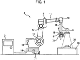
1 zeigt eine Seitenansicht eines ersten Robotersystems gemäß einer Ausführungsform. 1 shows a side view of a first robot system according to an embodiment.
-
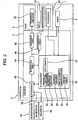
2 zeigt ein Blockdiagramm eines Robotersystems gemäß der Ausführungsform. 2 shows a block diagram of a robot system according to the embodiment.
-
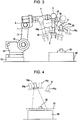
3 zeigt eine Seitenansicht eines Roboters zum Darstellen der Bewegung einer Kamera im ersten Robotersystem. 3 shows a side view of a robot for illustrating the movement of a camera in the first robot system.
-
4 zeigt eine Seitenansicht einer Kamera und eines Werkstücks zum Darstellen einer Erfassungsposition der Kamera. 4 shows a side view of a camera and a workpiece for representing a detection position of the camera.
-
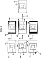
5 zeigt ein Diagramm von durch ein Steuergerät zu verarbeitenden Bildern. 5 shows a diagram of images to be processed by a controller.
-
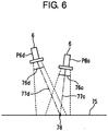
6 zeigt eine Seitenansicht der Kamera und die Erfassungsfläche zum Darstellen der Beziehung zwischen Pixeln in einem aktuell erfassten ersten Bild und Pixeln in einem zweiten Bild zum Zeitpunkt der Annahme, dass die Kamera an einer Erfassungsposition angeordnet ist. 6 Fig. 12 shows a side view of the camera and the detection surface for illustrating the relationship between pixels in a currently acquired first image and pixels in a second image at the time of assuming that the camera is located at a detection position.
-
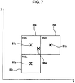
7 zeigt ein Diagramm zum Darstellen von durch Vergrößern des ersten Bildes, das aktuell erfasst wurde, ermittelten Pixeln. 7 Fig. 10 is a diagram showing pixels obtained by enlarging the first image currently detected.
-
8 zeigt ein erläuterndes Diagramm in Bezug auf ein Verfahren zum Berechnen von Pixelwerten im zweiten Bild zum Zeitpunkt der Annahme, dass das Bild an der Erfassungsposition erfasst wird. 8th Fig. 12 is an explanatory diagram relating to a method of calculating pixel values in the second image at the time of assuming that the image is detected at the detection position.
-
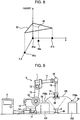
9 zeigt eine Seitenansicht eines zweiten Robotersystems gemäß der Ausführungsform. 9 shows a side view of a second robot system according to the embodiment.
-
10 zeigt eine weitere Seitenansicht des zweiten Robotersystems der Ausführungsform. 10 shows another side view of the second robot system of the embodiment.
-
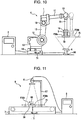
11 zeigt eine Seitenansicht eines Fördersystems gemäß der Ausführungsform. 11 shows a side view of a conveyor system according to the embodiment.
-
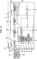
12 zeigt ein Blockdiagramm des Fördersystems gemäß der Ausführungsform. 12 shows a block diagram of the conveyor system according to the embodiment.
-
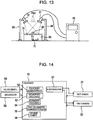
13 zeigt eine Seitenansicht einer Bildgebungsvorrichtung gemäß der Ausführungsform. 13 shows a side view of an imaging device according to the embodiment.
-
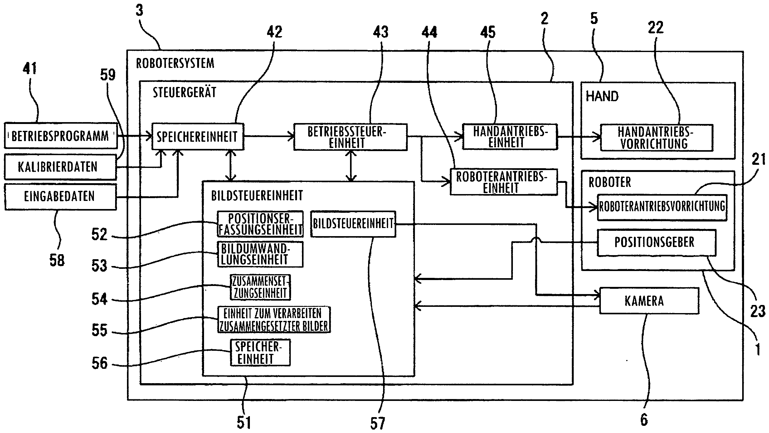
14 zeigt ein Blockdiagramm zum Darstellen der Bildgebungsvorrichtung gemäß der Ausführungsform. 14 FIG. 10 is a block diagram showing the imaging device according to the embodiment. FIG.
Ausführliche BeschreibungDetailed description
Nachfolgend ist eine Bildgebungsvorrichtung gemäß einer Ausführungsform in Bezug auf 1 bis 14 beschrieben. Die Bildgebungsvorrichtung gemäß der vorliegenden Ausführungsform erfasst und/oder prüft ein Werkstück auf der Basis eines von einem Sichtsensor erfassten Bildes.Hereinafter, an image forming apparatus according to an embodiment is described with reference to FIG 1 to 14 described. The imaging device according to the present embodiment detects and / or inspects a workpiece based on an image detected by a visual sensor.
1 zeigt eine schematische Ansicht eines ersten Robotersystems gemäß der vorliegenden Ausführungsform. 2 zeigt ein Blockdiagramm eines Robotersystems gemäß der vorliegenden Ausführungsform. Gemäß 1 und 2 umfasst ein Robotersystem 3 eine Hand 5, die ein Werkstück 38 greift, und einen Roboter 1, der die Hand 5 bewegt. Das Robotersystem 3 umfasst ein Steuergerät 2, welches das Robotersystem 3 steuert. Ferner umfasst das Robotersystem 3 einen Montagetisch 95, auf dem das Werkstück 38 montiert ist. 1 shows a schematic view of a first robot system according to the present embodiment. 2 FIG. 12 is a block diagram of a robot system according to the present embodiment. FIG. According to 1 and 2 includes a robot system 3 one hand 5 that is a workpiece 38 attacks, and a robot 1 that's the hand 5 emotional. The robot system 3 includes a controller 2 which is the robot system 3 controls. Furthermore, the robot system includes 3 a mounting table 95 on which the workpiece 38 is mounted.
Die Hand 5 gemäß der vorliegenden Ausführungsform ist ein Endeffektor, der das Werkstück 38 greift und loslässt. Der am Roboter 1 befestigte Endeffektor ist nicht auf diese Form beschränkt und es kann ein beliebiges Vorgangswerkzeug verwendet werden, das für den Vorgang geeignet ist, den das Robotersystem 3 durchführt. Beispielsweise kann als Endeffektor ein Vorgangswerkzeug zum Schweißen oder ein Vorgangswerkzeug zum Anbringen eines Dichtmaterials an der Oberfläche des Werkstücks o. Ä. verwendet werden. Ferner ist gegebenenfalls nur eine Kamera 6 an einem Handende des Roboters 1 befestigt, ohne dass ein Vorgangswerkzeug am Handende des Roboters 1 befestigt ist.The hand 5 According to the present embodiment, an end effector is the workpiece 38 grabs and lets go. The one on the robot 1 Attached end effector is not limited to this form and any tool that is suitable for the operation that the robot system may be used 3 performs. For example, as an end effector, an operation tool for welding or an operation tool for attaching a sealing material to the surface of the workpiece o. Ä. be used. Further, if necessary, only one camera 6 at a hand end of the robot 1 attached without having a tool at the hand of the robot 1 is attached.
Der Roboter 1 gemäß der vorliegenden Ausführungsform ist ein Gelenkroboter umfassend eine Mehrzahl von Gelenken 18. Der Roboter 1 umfasst einen Oberarm 11 und einen Unterarm 12. Der Unterarm 12 wird von einer Drehbasis 13 gestützt. Die Drehbasis 13 wird von einer Basis 14 gestützt. Der Roboter 1 umfasst ein Handgelenk 15, das mit einem Endabschnitt des Oberarms 11 verbunden ist. Das Handgelenk 15 umfasst einen Flansch 16 zum Befestigen der Hand 5. Ein Bestandteil des Roboters 1 ist so ausgebildet, dass er sich um eine vorgegebene Antriebsachse dreht. Die Form des Roboters ist nicht auf solche eine Form beschränkt und es kann ein beliebiger Roboter verwendet werden, der das Vorgangswerkzeug bewegen kann.The robot 1 According to the present embodiment, a joint robot comprising a plurality of joints 18 , The robot 1 includes an upper arm 11 and a forearm 12 , Forearm 12 is from a rotary base 13 supported. The rotary base 13 is from a base 14 supported. The robot 1 includes a wrist 15 that with one end portion of the upper arm 11 connected is. The wrist 15 includes a flange 16 for attaching the hand 5 , A component of the robot 1 is designed to rotate about a given drive axis. The shape of the robot is not limited to such a shape, and any robot that can move the operation tool can be used.
Der Roboter 1 gemäß der vorliegenden Ausführungsform umfasst eine Roboterantriebsvorrichtung 21, die Bestandteile wie den Oberarm 11 antreibt. Die Roboterantriebsvorrichtung 21 umfasst Antriebsmotoren, die den Oberarm 11, den Unterarm 12, die Drehbasis 13 und das Handgelenk 15 antreiben. Richtungen der entsprechenden Bestandteile des Roboters 1 ändern sich am Gelenk 18, wobei sich die Position und die Ausrichtung des Roboters 1 ändern. Die Hand 5 umfasst eine Handantriebsvorrichtung 22, welche die Hand 5 antreibt. Die Handantriebsvorrichtung 22 gemäß der vorliegenden Ausführungsform treibt die Hand 5 durch pneumatischen Druck an. Die Handantriebsvorrichtung 22 umfasst eine Pneumatikpumpe und ein Magnetventil zum Versorgen von Zylindern mit Druckluft.The robot 1 According to the present embodiment, a robot drive device comprises 21 , the ingredients like the upper arm 11 drives. The robot drive device 21 includes drive motors that cover the upper arm 11 , the forearm 12 , the rotation base 13 and the wrist 15 drive. Directions of the corresponding components of the robot 1 change at the joint 18 , where the position and orientation of the robot 1 to change. The hand 5 includes a hand drive device 22 which the hand 5 drives. The hand drive device 22 according to the present embodiment drives the hand 5 by pneumatic pressure. The hand drive device 22 includes a pneumatic pump and a solenoid valve to supply cylinders with compressed air.
Das Steuergerät 2 steuert den Roboter 1 und die Hand 5. Das Steuergerät 2 umfasst eine arithmetische Verarbeitungsvorrichtung (Rechner) mit einer CPU (Central Processing Unit) und ein RAM (Random Access memory) und ein ROM (Read Only Memory) u. Ä., die über einen Bus mit der CPU verbunden sind. Der Roboter 1 wird gemäß Betätigungsbefehlen vom Steuergerät 2 angetrieben. Der Roboter 1 transportiert das Werkstück 38 automatisch gemäß einem Betriebsprogramm 41. Die Roboterantriebsvorrichtung 21 und die Handantriebsvorrichtung 22 werden vom Steuergerät 2 gesteuert.The control unit 2 controls the robot 1 and the hand 5 , The control unit 2 comprises an arithmetic processing apparatus (computer) having a CPU (Central Processing Unit) and a RAM (Random Access Memory) and a ROM (Read Only Memory) and the like. Ä., Which are connected via a bus to the CPU. The robot 1 is in accordance with actuation commands from the controller 2 driven. The robot 1 transports the workpiece 38 automatically according to an operating program 41 , The robot drive device 21 and the hand drive device 22 be from the controller 2 controlled.
Das Betriebsprogramm 41, das vorab zum Betreiben des Roboters 1 vorbereitet wurde, wird am Steuergerät 2 eingegeben. Das Betriebsprogramm 41 wird in einer Speichereinheit 42 gespeichert. Eine Betriebssteuereinheit 43 sendet einen Betätigungsbefehl an eine Roboterantriebseinheit 44 zum Antreiben des Roboters 1 gemäß dem Betriebsprogramm 41. Die Roboterantriebseinheit 44 umfasst eine elektrische Schaltung zum Antrieb von Antriebsmotoren und versorgt die Roboterantriebsvorrichtung 21 mit Strom gemäß Betätigungsbefehlen.The operating program 41 , the advance to operate the robot 1 has been prepared, is at the control unit 2 entered. The operating program 41 is in a storage unit 42 saved. An operation control unit 43 sends an actuation command to a robot drive unit 44 for driving the robot 1 according to the operating program 41 , The robot drive unit 44 includes an electric circuit for driving drive motors and supplies the robot drive device 21 with current according to actuation commands.
Ferner sendet die Betriebssteuereinheit 43 einen Betätigungsbefehl zum Antreiben der Handantriebsvorrichtung 22 an eine Handantriebseinheit 45. Die Handantriebseinheit 45 umfasst eine elektrische Schaltung zum Antrieb der Pneumatikpumpe u. Ä. und versorgt die Pneumatikpumpe u. Ä. mit Strom gemäß Betätigungsbefehlen.Further, the operation control unit transmits 43 an operation command for driving the manual drive device 22 to a hand drive unit 45 , The hand drive unit 45 includes an electrical circuit for driving the pneumatic pump u. Ä. and supplies the pneumatic pump u. Ä. with current according to actuation commands.
Der Roboter 1 umfasst einen Zustandsgeber zum Erfassen einer Position und einer Ausrichtung des Roboters 1. Der Zustandsgeber gemäß der vorliegenden Ausführungsform umfasst einen Positionsgeber 23, der an einem Antriebsmotor für jede Antriebsachse der Roboterantriebsvorrichtung 21 befestigt ist. Beispielsweise kann der Positionsgeber 23 Drehwinkel zum Zeitpunkt, zu dem der Antriebsmotor der Roboterantriebsvorrichtung 21 angetrieben wird, erfassen. Die Position und die Ausrichtung des Roboters 1 werden von der Ausgabe vom Positionsgeber 23 erfasst. Der Zustandsgeber ist nicht auf den Positionsgeber, der am Antriebsmotor befestigt ist, beschränkt und es kann ein beliebiger Geber verwendet werden, der die Position und die Ausrichtung des Roboters 1 erfassen kann.The robot 1 includes a state transmitter for detecting a position and an orientation of the robot 1 , The state generator according to the present embodiment includes a position sensor 23 to a drive motor for each drive axle of the robot drive device 21 is attached. For example, the position sensor 23 Angle of rotation at the time when the drive motor of the robot drive device 21 is driven, capture. The position and orientation of the robot 1 are from the output from the locator 23 detected. The state transmitter is not limited to the position encoder attached to the drive motor, and any encoder can be used that determines the position and orientation of the robot 1 can capture.
Ein Referenzkoordinatensystem 71, das sich nicht bewegt, wenn sich die Position und die Ausrichtung des Roboters 1 ändern, ist im Robotersystem 3 eingerichtet. Im in 1 dargestellten Beispiel ist der Ursprung des Referenzkoordinatensystems 71 in der Basis 14 des Roboters 1 angeordnet. Das Referenzkoordinatensystem 71 wird ebenfalls als Weltkoordinatensystem bezeichnet. Im Referenzkoordinatensystem 71 ist die Position des Ursprungs festgelegt und die Richtung von jeder Koordinatenachse ist ebenfalls festgelegt. Weder die Position noch die Ausrichtung des Referenzkoordinatensystems 71 ändern sich, selbst wenn sich die Position und die Ausrichtung des Roboters 1 ändern. Das Referenzkoordinatensystem 71 weist eine X-Achse, eine Y-Achse und eine Z-Achse auf, die jeweils als eine Koordinatenachse dienen und senkrecht zueinander sind. Ferner ist eine W-Achse als eine Koordinatenachse um die X-Achse festgelegt. Eine P-Achse ist als eine Koordinatenachse um die Y-Achse festgelegt. Eine R-Achse ist als eine Koordinatenachse um die Z-Achse festgelegt.A reference coordinate system 71 that does not move when the position and orientation of the robot 1 change is in the robot system 3 set up. Im in 1 The example shown is the origin of the reference coordinate system 71 in the base 14 of the robot 1 arranged. The reference coordinate system 71 is also called the world coordinate system. In the reference coordinate system 71 the position of the origin is fixed and the direction of each coordinate axis is also fixed. Neither the position nor the orientation of the reference coordinate system 71 change, even if the position and orientation of the robot 1 to change. The reference coordinate system 71 has an X-axis, a Y-axis, and a Z-axis, each serving as a coordinate axis and being perpendicular to each other. Further, a W axis is set as a coordinate axis about the X axis. A P-axis is defined as a coordinate axis about the Y-axis. An R-axis is defined as a coordinate axis about the Z-axis.
Ferner ist ein Flanschkoordinatensystem 72 auf einer Fläche der Oberfläche des Flansches 16, auf dem die Hand 5 befestigt ist, festgelegt. Das Flanschkoordinatensystem 72 wird ebenfalls als Handenden-Koordinatensystem bezeichnet. Der Ursprung des Flanschkoordinatensystems 72 ist auf der Drehachse des Flanschs 16 angeordnet. Das Flanschkoordinatensystem 72 weist eine X-Achse, eine Y-Achse und eine Z-Achse auf, die senkrecht zueinander sind. Ferner weist das Flanschkoordinatensystem 72 eine W-achse um die X-Achse, eine P-Achse um die Y-Achse und eine R-Achse um die Z-Achse auf. Wenn sich die Position und die Ausrichtung des Roboters 1 ändern, ändern sich ebenfalls die Position des Ursprungs des Flanschkoordinatensystems 72 und die Ausrichtung des Koordinatensystems in Verbindung mit dem Flansch 16. Durch Umwandeln von Koordinatenwerten des Flanschkoordinatensystems 72 durch eine Matrix können Koordinatenwerte des Referenzkoordinatensystems 71 berechnet werden. Ferner können durch Umwandeln von Koordinatenwerten des Referenzkoordinatensystems 71 durch eine Matrix Koordinatenwerte des Flanschkoordinatensystems 72 berechnet werden.Further, a flange coordinate system 72 on a surface of the surface of the flange 16 on which the hand 5 fixed, fixed. The flange coordinate system 72 is also called the hand-end coordinate system. The origin of the flange coordinate system 72 is on the axis of rotation of the flange 16 arranged. The flange coordinate system 72 has an X-axis, a Y-axis and a Z-axis that are perpendicular to each other. Furthermore, the flange coordinate system 72 a W axis about the X axis, a P axis about the Y axis, and an R axis around the X axis Z axis up. If the position and orientation of the robot 1 change the position of the origin of the flange coordinate system 72 and the orientation of the coordinate system in conjunction with the flange 16 , By converting coordinate values of the flange coordinate system 72 Coordinate values of the reference coordinate system can be used by a matrix 71 be calculated. Further, by converting coordinate values of the reference coordinate system 71 through a matrix coordinate values of the flange coordinate system 72 be calculated.
Das Robotersystem 3 gemäß der vorliegenden Ausführungsform umfasst eine Bildgebungsvorrichtung, die ein Erfassen und/oder Prüfen des Werkstücks 38 durchführt. Beim ersten Robotersystem 3 wird die Position des Werkstücks 38 auf dem Montagetisch 95 erfasst, bevor die Hand 5 das Werkstück 38 greift. Die Bildgebungsvorrichtung umfasst die Kamera 6, die als ein Sichtsensor dient, der ein erstes Bild des Werkstücks 38 erfasst. Das erste Bild ist ein Bild, das durch aktuelles Erfassen des Bildes des Werkstücks 38 unter Verwendung der Kamera 6 ermittelt wird. Die Kamera 6 gemäß der vorliegenden Ausführungsform ist eine Kamera, die ein zweidimensionales Bild erfasst. Die Kamera 6 wird vom Roboter 1 gestützt. Die Kamera 6 ist durch ein Stützelement am Handgelenk 15 befestigt. Die Kamera 6 ist am Roboter 1 befestigt, so dass das Bild des Werkstücks 38 erfasst werden kann, wenn der Roboter 1 seine Position und Ausrichtung ändert.The robot system 3 According to the present embodiment, an image forming apparatus includes detecting and / or inspecting the workpiece 38 performs. At the first robot system 3 becomes the position of the workpiece 38 on the assembly table 95 captured before the hand 5 the workpiece 38 attacks. The imaging device includes the camera 6 serving as a visual sensor, which is a first image of the workpiece 38 detected. The first image is an image obtained by currently capturing the image of the workpiece 38 using the camera 6 is determined. The camera 6 According to the present embodiment, a camera that captures a two-dimensional image. The camera 6 is from the robot 1 supported. The camera 6 is by a support element on the wrist 15 attached. The camera 6 is on the robot 1 attached, leaving the picture of the workpiece 38 can be detected when the robot 1 its position and orientation changes.
Die Bildgebungsvorrichtung gemäß der vorliegenden Ausführungsform umfasst eine Bewegungsvorrichtung, die das Werkstück 38 und die Kamera 6 so bewegt, dass sich eine relative Position des Werkstücks bzw. der Kamera in Bezug aufeinander ändert. Beim Robotersystem 3 dient der Roboter 1 als Bewegungsvorrichtung und die Kamera 6 ist am Handende des Roboters 1 montiert. Wenn sich die Position und die Ausrichtung des Roboters 1 ändern, ändern sich ebenfalls die Position und die Ausrichtung der Kamera 6. Ferner dient der Montagetisch 95 als ein Fixierungsteil zum Fixieren des Werkstücks 38.The imaging device according to the present embodiment includes a moving device that holds the workpiece 38 and the camera 6 moved so that a relative position of the workpiece or the camera with respect to each other changes. In the robot system 3 serves the robot 1 as a movement device and the camera 6 is at the hand of the robot 1 assembled. If the position and orientation of the robot 1 change the position and orientation of the camera 6 , Furthermore, the mounting table is used 95 as a fixing part for fixing the workpiece 38 ,
Die Bildgebungsvorrichtung umfasst eine Bildverarbeitungsvorrichtung, die das vom Sichtsensor erfasste erste Bild verarbeitet. Beim Robotersystem 3 gemäß der vorliegenden Ausführungsform dient das Steuergerät 2 als Bildverarbeitungsvorrichtung. Das Steuergerät 2 umfasst eine Bildsteuereinheit 51. Die Bildsteuereinheit 51 umfasst eine Bildgebungssteuereinheit 57, die an die Kamera 6 einen Befehl zum Erfassen eines Bildes sendet. Die Bildsteuereinheit 51 weist eine Funktion zum Verarbeiten eines von der Kamera 6 erfassten ersten Bildes auf. Die Bildsteuereinheit 51 umfasst eine Speichereinheit 56, die Informationen zur Bildgebung des Werkstücks 38 speichert.The imaging device includes an image processing device that processes the first image acquired by the visual sensor. In the robot system 3 According to the present embodiment, the controller is used 2 as an image processing device. The control unit 2 comprises an image control unit 51 , The image control unit 51 includes an imaging control unit 57 pointing to the camera 6 sends a command to capture an image. The image control unit 51 has a function to process one from the camera 6 captured first image. The image control unit 51 includes a storage unit 56 providing information for imaging the workpiece 38 stores.
3 zeigt eine Seitenansicht des Roboters zur Darstellung der Bewegung der Kamera, wenn das Bild des Werkstücks erfasst wird. Wenn sich die Position und die Ausrichtung des Roboters 1 ändern, ändern sich die Position und die Ausrichtung der Kamera 6. Die Kamera 6 kann an einer beliebigen Position angeordnet sein, an der das Bild des Werkstücks 38 erfasst werden kann. Beim ersten Robotersystem 3 werden die Bilder des Werkstücks 38 an einer Mehrzahl von vorgegebenen Positionen der Kamera 6 erfasst. Die Kamera 6 erfasst eine Mehrzahl von ersten Bildern an verschiedenen Bildgebungspositionen. Beim in 3 dargestellten Beispiel erfasst die Kamera 6 das Bild des Werkstücks 38 an der Position P6a. Anschließend, nachdem der Roboter 1 die Kamera 6 von der Position P6a zur Position P6B bewegt wie durch den Pfeil 91 angegeben, erfasst die Kamera 6 das Bild des Werkstücks 38. 3 shows a side view of the robot to illustrate the movement of the camera when the image of the workpiece is detected. If the position and orientation of the robot 1 change the position and orientation of the camera 6 , The camera 6 can be located at any position where the image of the workpiece 38 can be detected. At the first robot system 3 become the pictures of the workpiece 38 at a plurality of predetermined positions of the camera 6 detected. The camera 6 captures a plurality of first images at different imaging positions. When in 3 The example shown captures the camera 6 the picture of the workpiece 38 at the position P6a. Subsequently, after the robot 1 the camera 6 from position P6a to position P6B as indicated by the arrow 91 specified, the camera captures 6 the picture of the workpiece 38 ,
Ferner, nachdem der Roboter 1 die Kamera 6 zur Position P6c bewegt wie durch den Pfeil 92 angegeben, erfasst die Kamera 6 das Bild des Werkstücks 38. Auf diese Weise wird eine Mehrzahl von ersten Bildern des Werkstücks 38 erfasst, so dass sich eine Mehrzahl von relativen Positionen der Kamera 6 in Bezug auf das Werkstück 38 voneinander unterscheidet. Die Mehrzahl der Positionen P6a, P6b, P6c der Kamera 6, an der die ersten Bilder erfasst werden, sind vorgegeben. Ferner sind die Positionen und die Ausrichtungen des Roboters 1, die den Positionen P6a, P6b, P6c entsprechen, im Betriebsprogramm 41 festgelegt. Die Kamera 6 erfasst eine Mehrzahl von ersten Bildern an einer Mehrzahl von vorgegebenen Positionen und Ausrichtungen des Roboters 1.Further, after the robot 1 the camera 6 moved to position P6c as indicated by the arrow 92 specified, the camera captures 6 the picture of the workpiece 38 , In this way, a plurality of first images of the workpiece 38 captured, so that a plurality of relative positions of the camera 6 in relation to the workpiece 38 different from each other. The plurality of positions P6a, P6b, P6c of the camera 6 where the first images are captured are given. Further, the positions and orientations of the robot 1 corresponding to positions P6a, P6b, P6c in the operating program 41 established. The camera 6 detects a plurality of first images at a plurality of predetermined positions and orientations of the robot 1 ,
Die Kamera 6 kann eine Mehrzahl von ersten Bildern erfassen, ohne die Mehrzahl der Positionen und Ausrichtungen des Roboters 1 vorzugeben. Beispielsweise kann die Ausgangsposition der Kamera 6 als die Position P6a festgelegt werden und die Position der Kamera 6 nach dem Bewegen kann als Position P6b festgelegt werden. Die Bilder des Werkstücks 38 können in konstanten Zeitintervallen während der Zeit, in der die Kamera 6 von der Position P6a zur Position P6b bewegt wird, während der Roboter 1 angetrieben wird, erfasst werden. In solch einem Fall ist es erforderlich, dass die Positionen und die Ausrichtungen des Roboters 1 zum Zeitpunkt, zu dem die Kamera 6 die ersten Bilder erfasst, mit den entsprechenden ersten Bildern verknüpft werden, um einen Satz aus erstem Bild und der Position und der Ausrichtung des Roboters 1 zu bilden, und dieser Satz wird in der Speichereinheit 56 gespeichert. Zwar werden hier die Position und die Ausrichtung des Roboters 1 gespeichert; aber die Ausführung ist nicht hierauf beschränkt. Die Position und die Ausrichtung der Kamera 6 oder eine andere Position, die auf der Basis der Position und der Ausrichtung des Roboters 1 berechnet werden können, kann in der Speichereinheit 56 gespeichert werden.The camera 6 can capture a plurality of first images without the majority of the positions and orientations of the robot 1 pretend. For example, the home position of the camera 6 as the position P6a and the position of the camera 6 after moving it can be set as position P6b. The pictures of the workpiece 38 can be at constant time intervals during the time the camera is in 6 from the position P6a to the position P6b while the robot 1 is driven to be detected. In such a case, it is necessary that the positions and orientations of the robot 1 at the time the camera came to 6 The first images captured are linked to the corresponding first images to form a set of the first image and the position and orientation of the robot 1 to form, and this sentence is in the memory unit 56 saved. Although here are the position and orientation of the robot 1 saved; but the execution is not limited to this. The position and orientation of the camera 6 or another position on the Base the position and orientation of the robot 1 can be calculated in the storage unit 56 get saved.
4 zeigt eine Seitenansicht zum Erläutern der Positionen der Kamera, an denen die Bilder des Werkstücks erfasst werden, und der Position der Kamera, die einem zum Erfassen des Werkstücks verwendeten Bild entspricht. In der vorliegenden Ausführungsform wird eine zum Erfassen des Werkstücks 38 verwendete Erfassungsfläche 75 vorab am Werkstück 38 definiert. Die Bildsteuereinheit 51 erfasst die Position des Werkstücks 38 auf der Erfassungsfläche 75. Die Erfassungsfläche 75 kann so festgelegt werden, dass sie sich entlang der Fläche eines Teils des Werkstücks 38 erstreckt. Insbesondere kann die Erfassungsfläche 75 so festgelegt werden, dass sie die Fläche eines Teils des Werkstücks 38 umfasst. Die Bildsteuereinheit 51 verwendet auf dieser Fläche gezeigte Merkmalspunkte oder Helligkeitswerte, um eine Erfassung und/oder Prüfung des Werkstücks 38 durchzuführen. Die Erfassungsfläche 75 kann im Referenzkoordinatensystem 71 ausgedrückt werden. Informationen über die Erfassungsfläche 75 werden in der Speichereinheit 56 gespeichert. Es können verschiedene Abschnitte für die Merkmalspunkte verwendet werden und bei der vorliegenden Ausführungsform werden Randpunkte als Merkmalspunkte verwendet. Die Randpunkte sind Punkte, an denen der Stärkegradient im Bild groß ist, und können zum Ermitteln der Form der Kontur des Werkstücks 38 verwendet werden. Das Verfahren zum Extrahieren von Randpunkten entspricht dem Stand der Technik und daher wird auf eine Erläuterung von diesem verzichtet. 4 Fig. 11 is a side view for explaining the positions of the camera at which the images of the workpiece are detected and the position of the camera corresponding to an image used for detecting the workpiece. In the present embodiment, one for detecting the workpiece 38 used detection area 75 in advance on the workpiece 38 Are defined. The image control unit 51 detects the position of the workpiece 38 on the detection surface 75 , The detection area 75 Can be set so that they are along the surface of a part of the workpiece 38 extends. In particular, the detection area 75 be set so that they are the area of a part of the workpiece 38 includes. The image control unit 51 uses feature points or brightness values shown on this surface to detect and / or inspect the workpiece 38 perform. The detection area 75 can in the reference coordinate system 71 be expressed. Information about the detection area 75 be in the storage unit 56 saved. Different sections may be used for the feature points, and in the present embodiment edge points are used as feature points. The edge points are points where the intensity gradient in the image is large and can be used to determine the shape of the contour of the workpiece 38 be used. The method for extracting edge points corresponds to the prior art and therefore an explanation thereof is omitted.
Die Positionen, an denen die Kamera 6 erste Bilder erfasst, sind die Positionen P6a, P6b, P6c. Wiederum wird eine Erfassungsposition P6D, die eine Position der Kamera 6 ist, an der das Werkstück 38 erfasst wird, vorab ermittelt. Die Erfassungsposition P6D ist eine von einem Bediener festgelegte imaginäre Position. Die Erfassungsposition P6D kann auf eine beliebige Position festgelegt werden, an der die Kamera 6 das Bild des Werkstücks 38 erfassen kann. Ferner werden die Position und Ausrichtung des Roboters 1, die zum Anordnen der Kamera 6 an der Erfassungsposition 6d verwendet werden, als Sollposition der Bewegungsvorrichtung vorgegeben. Die Position und die Ausrichtung des Roboters 1 werden in der Speichereinheit 56 gespeichert. Informationen über die Erfassungsposition P6d der Kamera 6 können durch Verwenden des Referenzkoordinatensystems 71 in der Speichereinheit 56 gespeichert werden. Die Erfassungsposition P6d ist nicht auf eine imaginäre Position beschränkt und es kann eine Position aus Positionen der Kamera 6 ausgewählt werden, an denen eine Mehrzahl von ersten Bildern erfasst wird.The positions where the camera 6 When the first images are detected, the positions are P6a, P6b, P6c. Again, a detection position P6D, which is a position of the camera 6 is where the workpiece is 38 is determined in advance. The detection position P6D is an imaginary position set by an operator. The detection position P6D can be set to any position where the camera 6 the picture of the workpiece 38 can capture. Further, the position and orientation of the robot 1 for arranging the camera 6 at the entry position 6d can be used, given as the target position of the movement device. The position and orientation of the robot 1 be in the storage unit 56 saved. Information about the detection position P6d of the camera 6 can by using the reference coordinate system 71 in the storage unit 56 get saved. The detection position P6d is not limited to an imaginary position and may be a position of positions of the camera 6 are selected, at which a plurality of first images is detected.
5 zeigt eine schematische Ansicht zum Erläutern eines in der vorliegenden Ausführungsform erfassten erstens Bildes und von Verarbeitungen des ersten Bildes. Gemäß 2, 4 und 5 erfasst die Kamera 6 erste Bilder 61a, 61b, 61c an den Positionen P6a, P6b, P6c. Das erste Bild 61a ist ein von der Kamera 6 an der Position P6a erfasstes Bild, das erste Bild 61b ist ein von der Kamera 6 an der Position P6b erfasstes Bild und das erste Bild 61c ist ein von der Kamera 6 an der Position P6c erfasstes Bild. Anschließend wandelt die Bildsteuereinheit 51 die ersten Bilder 61a, 61b, 61c jeweils in zweite Bilder 62a, 62b, 62c um, wenn sie an der Erfassungsposition P6d erfasst werden, wie durch den Pfeil 93 angegeben. 5 FIG. 12 is a schematic view for explaining a first image acquired in the present embodiment and processes of the first image. FIG. According to 2 . 4 and 5 captures the camera 6 first pictures 61a . 61b . 61c at the positions P6a . P6b . P6C , The first picture 61a is one of the camera 6 at the position P6a Captured image, the first image 61b is one of the camera 6 at the position P6b captured image and the first image 61c is one of the camera 6 at the position P6C captured image. Subsequently, the image control unit converts 51 the first pictures 61a . 61b . 61c each in second pictures 62a . 62b . 62c around when at the detection position P6d be detected, as indicated by the arrow 93 specified.
Die zweiten Bilder 62a, 62b, 62c sind unter der Annahme, dass das Werkstück 38, das in den von der Kamera 6 erfassten ersten Bilder 61a, 61b, 61c dargestellt ist, von der Erfassungsposition P6d erfasst wird, ermittelte Bilder. Das zweite Bild 62a ist ein durch Umwandeln des erstens Bildes 61a in dieses ermitteltes Bild, das zweite Bild 62b ist ein durch Umwandeln des ersten Bildes 61b in dieses ermitteltes Bild und das zweite Bild 62c ist ein durch Umwandeln des ersten Bildes 61c in dieses ermitteltes Bild.The second pictures 62a . 62b . 62c are assuming that the workpiece 38 in the from the camera 6 captured first pictures 61a . 61b . 61c is shown from the detection position P6d is captured, determined images. The second picture 62a is one by converting the first picture 61a in this determined image, the second image 62b is one by converting the first image 61b in this determined image and the second image 62c is one by converting the first image 61c into this determined image.
Anschließend setzt die Bildsteuereinheit 51 die Mehrzahl der zweiten Bilder 62a, 62b, 62c zusammen, um ein zusammengesetztes Bild 63 zu erzeugen wie durch den Pfeil 94 angegeben. Einige Randpunkte des Werkstücks 38 können in den ersten Bildern 61a, 61b, 61c, die aktuell erfasst wurden, unklar sein. Beispielsweise kann die Linie der Kontur des Werkstücks 38 aufgrund des Auftretens einer Lichthofbildung an einem Abschnitt 65 des ersten Bildes 61b, das aktuell erfasst wurde, unklar sein. Auch in solch einem Fall kann der unklare Abschnitt durch Erzeugen des zusammengesetzten Bildes 63 ausgeschlossen werden.Then sets the image control unit 51 the majority of the second pictures 62a . 62b . 62c together to form a composite picture 63 to generate as by the arrow 94 specified. Some edge points of the workpiece 38 can in the first pictures 61a . 61b . 61c that are currently recorded, be unclear. For example, the line may be the contour of the workpiece 38 due to the occurrence of halation on a section 65 of the first picture 61b that was currently captured, be unclear. Even in such a case, the unclear portion may be generated by generating the composite image 63 be excluded.
Somit kann die Bildsteuereinheit 51 die Position des Werkstücks 38 genau erfassen. Danach korrigiert die Betriebssteuereinheit 43 die Position und die Ausrichtung des Roboters 1 auf der Basis der Position des Werkstücks 38. Diese Steuerung ermöglicht der Hand 5 das Greifen des Werkstücks 38.Thus, the image control unit 51 the position of the workpiece 38 capture exactly. After that, the operation control unit corrects 43 the position and orientation of the robot 1 based on the position of the workpiece 38 , This control allows the hand 5 the gripping of the workpiece 38 ,
Nachfolgend ist in Bezug auf 2 bis 5 eine Steuerung der vorliegenden Ausführungsform ausführlich beschrieben. Der Bediener führt vorab eine Kalibrierung der Kamera 6 durch. Es wird angenommen, dass Kalibrierdaten 59 ermittelt werden, um eine Beziehung zwischen einem Kamerakoordinatensystem, das als Basis für die Messverarbeitung durch die Kamera 6 dient, und dem Referenzkoordinatensystem herzustellen. Die Kalibrierdaten 59 werden in der Speichereinheit 42 gespeichert. Die Bildsteuereinheit 51 ermittelt die Kalibrierdaten 59 von der Speichereinheit 42 und speichert diese in der Speichereinheit 56. Die Kalibrierdaten 59 umfassen intrinsische Parameter umfassend Informationen beispielsweise zur Brennweite der Kamera 6 und Verzerrung einer Linse. Ferner umfassen die Kalibrierdaten 59 extrinsische Parameter umfassend eine relative Positionsbeziehung des Flanschkoordinatensystems 72 in Bezug auf das Bildkoordinatensystem 73 im von der Kamera 6 erfassten ersten Bild.The following is in relation to 2 to 5 a controller of the present embodiment will be described in detail. The operator performs a calibration of the camera in advance 6 by. It is assumed that calibration data 59 be determined to establish a relationship between a camera coordinate system as the basis for the measurement processing by the camera 6 serves to establish and the reference coordinate system. The calibration data 59 be in the storage unit 42 saved. The image control unit 51 determines the calibration data 59 from the storage unit 42 and stores them in the storage unit 56 , The calibration data 59 include intrinsic parameters including information about, for example, the focal length of the camera 6 and distortion of a lens. Furthermore, the calibration data include 59 extrinsic parameters comprising a relative positional relationship of the flange coordinate system 72 with respect to the image coordinate system 73 im from the camera 6 captured first picture.
Ferner gibt der Bediener Eingabedaten 58 am Steuergerät 2 ein. Die Eingabedaten 58 werden in der Speichereinheit 42 gespeichert. Die Bildsteuereinheit 51 ermittelt die Eingabedaten 58 von der Speichereinheit 42 und speichert diese in der Speichereinheit 56. Die Eingabedaten 58 umfassen Informationen zur Erfassungsfläche 75. Die Erfassungsfläche 75 kann auf einer ebenen Fläche festgelegt werden.Further, the operator inputs input data 58 at the control unit 2 on. The input data 58 be in the storage unit 42 saved. The image control unit 51 determines the input data 58 from the storage unit 42 and stores them in the storage unit 56 , The input data 58 include information about the detection area 75 , The detection area 75 can be set on a flat surface.
Alternativ kann die Erfassungsfläche 75 eine Kurve umfassen oder kann durch Verbinden einer Mehrzahl von Polygonen miteinander gebildet werden.Alternatively, the detection area 75 comprise a curve or may be formed by joining a plurality of polygons together.
Die Erfassungsfläche 75 gemäß der vorliegenden Ausführungsform wird vorab von einem Bediener festgelegt. Die Erfassungsfläche ist nicht auf diesen Modus beschränkt und es kann auch eine vorgegebene Fläche des Werkstücks durch Verwenden eines anderen Sensors gemessen werden und eine Erfassungsfläche wird so festgelegt, dass sie diese vorgegebene Fläche umfasst.The detection area 75 According to the present embodiment, it is set in advance by an operator. The detection area is not limited to this mode, and also a predetermined area of the workpiece may be measured by using another sensor, and a detection area is set to include this predetermined area.
Ferner gibt der Bediener vor, welche Position des Bildes verwendet wird, um ein zusammengesetztes Bild zu erzeugen, das am Ende zu erzeugen ist. Die Eingabedaten 58 umfassen die Position und die Ausrichtung des Roboters 1, um die Kamera 6 an der Erfassungsposition P6d zum Erfassen der Position des Werkstücks 38 anzuordnen. Für ein Bild, das der Erfassungsposition P6d entspricht, können Bedingungen verwendet werden, die sich von Bildgebungsbedingungen unterscheiden, wenn das Bild des Werkstücks 38 aktuell erfasst wird. Beispielsweise können für ein Bild, das der Erfassungsposition P6d entspricht, Werte festgelegt werden, die sich von denen, die verwendet werden, wenn ein Bild aktuell erfasst wird, in Bezug auf Brennweite, Blickwinkel, Pixelzahl, Linsenverzerrung u. Ä. der Kamera unterscheiden. Diese Informationsteile können in den Eingabedaten 58 enthalten sein.Further, the operator specifies which position of the image is used to produce a composite image that is to be created at the end. The input data 58 include the position and orientation of the robot 1 to the camera 6 at the entry position P6d for detecting the position of the workpiece 38 to arrange. For an image, the capture position P6d may correspond to conditions other than imaging conditions when the image of the workpiece 38 currently being recorded. For example, for an image, the capture position P6d Similarly, values that are different from those used when an image is currently captured may be set in terms of focal length, viewing angle, pixel count, lens distortion, and the like. Ä. distinguish the camera. These pieces of information may be in the input data 58 be included.
Die Position und die Ausrichtung des Roboters 1 zum Erfassen des ersten Bildes werden vorab im Betriebsprogramm 41 festgelegt. Gemäß dem Betriebsprogramm 41 ändert die Betriebssteuereinheit 43 die Position und die Ausrichtung des Roboters 1, um das Bild des Werkstücks 38 zu erfassen. Die Bildgebungssteuereinheit 57 sendet an die Kamera 6 einen Befehl zum Erfassen des Bildes des Werkstücks 38, wenn der Roboter 1 die Position und die Ausrichtung erreicht, die vorgegeben wurden. Die Kamera 6 erfasst Bilder des Werkstücks 38 an einer Mehrzahl von vorgegebenen Positionen P6a, P6b, P6c. In 3 werden zwar die ersten Bilder 61a, 61b, 61c an den Positionen P6a, P6b, P6c erfasst; aber die Ausführungsform ist nicht hierauf beschränkt und es können zwei oder mehr erste Bilder von beliebigen Positionen erfasst werden. Für die Position der Kamera 6, die das Bild des Werkstücks 38 erfasst kann eine beliebige Position gewählt werden, an der das Werkstück 38 im Sichtfeld der Kamera 6 liegt. Auf diese Weise werden die Bilder des Werkstücks 38 von einer Mehrzahl von Blickpunkten erfasst.The position and orientation of the robot 1 to capture the first image are in advance in the operating program 41 established. According to the operating program 41 changes the operation control unit 43 the position and orientation of the robot 1 to the picture of the workpiece 38 capture. The imaging control unit 57 sends to the camera 6 a command to capture the image of the workpiece 38 if the robot 1 reached the position and orientation that were given. The camera 6 captures images of the workpiece 38 at a plurality of predetermined positions P6a . P6b . P6C , In 3 are indeed the first pictures 61a . 61b . 61c at the positions P6a . P6b . P6C detected; but the embodiment is not limited thereto, and two or more first images of arbitrary positions can be detected. For the position of the camera 6 representing the image of the workpiece 38 can be selected any position at which the workpiece 38 in the field of view of the camera 6 lies. In this way, the images of the workpiece 38 captured from a plurality of viewpoints.
Im in 3 dargestellten Beispiel wird zwar eine Mehrzahl von Antriebsachsen des Roboters 1 angetrieben; die Ausführungsform ist aber nicht hierauf beschränkt und es kann eine einzelne Antriebsachse betrieben werden, um die Position der Kamera 6 zu ändern. Durch Verwenden dieser Steuerung wird ein Fehler verhindert, der auftritt, wenn der Bestandteil des Roboters 1 an der Antriebsachse in Betrieb ist. Ferner ist, obgleich sich die Richtung der Kamera 6 (Richtung der optischen Achse) im in 3 dargestellten Beispiel ändert, die Ausführungsform nicht hierauf beschränkt und es kann ein paralleles Verschieben der Kamera 6 ohne Ändern der Richtung der Kamera 6 durchgeführt werden.Im in 3 Although the example shown becomes a plurality of drive axes of the robot 1 driven; however, the embodiment is not limited to this and a single drive axle can be operated to control the position of the camera 6 to change. By using this control, an error that occurs when the component of the robot is prevented 1 is in operation on the drive axle. Furthermore, although the direction of the camera 6 (Direction of the optical axis) in 3 As shown, the embodiment is not limited to this, and it may be a parallel shift of the camera 6 without changing the direction of the camera 6 be performed.
Die Bildsteuereinheit 51 umfasst eine Positionserfassungseinheit 52, die eine relative Position der Kamera 6 in Bezug auf das Werkstück 38 ermittelt. Die Positionserfassungseinheit 52 ermittelt die Position und die Ausrichtung des Roboters 1, wenn das Bild des Werkstücks 38 erfasst wird. Die Positionserfassungseinheit 52 berechnet die Position der Kamera 6, wenn das Bild des Werkstücks 38 erfasst wird, auf der Basis der Position und der Ausrichtung des Roboters 1 und der Kalibrierdaten 59. Die Speichereinheit 56 speichert eine Mehrzahl der von der Kamera 6 an einer Mehrzahl von Positionen erfassten ersten Bilder. Ferner speichert die Speichereinheit 56 einen Satz aus Position und Ausrichtung des Roboters 1, wenn das erste Bild erfasst wird, und das erste Bild.The image control unit 51 includes a position detection unit 52 indicating a relative position of the camera 6 in relation to the workpiece 38 determined. The position detection unit 52 determines the position and orientation of the robot 1 when the picture of the workpiece 38 is detected. The position detection unit 52 calculates the position of the camera 6 when the picture of the workpiece 38 based on the position and orientation of the robot 1 and the calibration data 59 , The storage unit 56 stores a majority of those from the camera 6 captured at a plurality of positions first images. Further, the storage unit stores 56 a set of position and orientation of the robot 1 when the first image is captured, and the first image.
Das Bildsteuergerät 51 umfasst eine Bildumwandlungseinheit 53, die eine Mehrzahl der von der Kamera 6 erfassten ersten Bilder 61a, 61b, 61c in eine Mehrzahl der zweiten Bilder 62a, 62b, 62c, wenn angenommen wird, dass die Bilder an der Erfassungsposition P6d erfasst werden, auf der Basis der relativen Position der Kamera 6 in Bezug auf die Erfassungsfläche 75 umwandelt. In diesem Beispiel wandelt die Bildumwandlungseinheit 53 die ersten Bilder 61a, 61b, 61c auf der Basis der Positionen und der Ausrichtungen des Roboters 1 um, wenn die Bilder des Werkstücks 38 erfasst werden, wobei die Position und die Ausrichtung so gespeichert werden, dass sie mit den ersten Bildern 61a, 61b, 61c verknüpft werden. Die Bildumwandlungseinheit 53 führt eine Umwandlung in zweite Bilder 62a, 62b, 62c des Werkstücks 38 durch, von denen jedes ermittelt wird, wenn angenommen wird, dass in den ersten Bildern 61a, 61b, 61c enthaltene Werkstücke 38 jeweils an der Sollposition des Roboters 1 erfasst werden, die der Erfassungsposition P6d entspricht. Die zweiten Bilder 62a, 62b, 62c können als von der gleichen imaginären Position erfasste imaginäre Bilder bezeichnet werden. Nachfolgend ist ein Prozess beschrieben, in dem die ersten Bilder 61a, 61b, 61c, die aktuell in 5 erfasst werden, in ein zweites Bild 62a beim Erfassen an der Erfassungsposition P6d umgewandelt werden.The image controller 51 comprises an image conversion unit 53 which is a majority of the camera 6 captured first pictures 61a . 61b . 61c into a plurality of the second images 62a . 62b . 62c if it is assumed that the images are at the detection position P6d be captured, based on the relative position of the camera 6 in terms of the detection area 75 transforms. In this example, the image conversion unit converts 53 the first pictures 61a . 61b . 61c based on the positions and orientations of the robot 1 around when the pictures of the workpiece 38 be captured, with the position and orientation being stored so that they match the first images 61a . 61b . 61c be linked. The image conversion unit 53 performs a conversion into second images 62a . 62b . 62c of the workpiece 38 each of which is determined if it is assumed that in the first images 61a . 61b . 61c included workpieces 38 each at the target position of the robot 1 be recorded, the detection position P6d equivalent. The second pictures 62a . 62b . 62c may be referred to as imaginary images captured from the same imaginary position. Below is a process described in which the first pictures 61a . 61b . 61c currently in 5 be captured in a second image 62a when entering at the entry item P6d being transformed.
6 zeigt eine Seitenansicht zum Erläutern der Sichtlinie der Kamera, wenn das erste Bild aktuell erfasst wird, und die Sichtlinie der an der Erfassungsposition angeordneten Kamera. 6 zeigt die an der Position P6c angeordnete Kamera 6, an der die Bildgebung aktuell durchgeführt wird, und die an der Erfassungsposition P6d angeordnete Kamera 6. Es können Bildgebungsflächen 76c, 76d im Blickwinkel der Kamera 6 festgelegt werden. Die Bildgebungsflächen 76c, 76d simulieren jeweils eine Fläche eines Bildsensors, etwa eines CCD-(Charge-Coupled-Device-)Sensors und eines CMOS-(Complementary-Metal-Oxide-Semiconductor-)Sensors, die in der Kamera 6 angeordnet sind. 6 FIG. 12 is a side view for explaining the line of sight of the camera when the first image is currently detected and the line of sight of the camera located at the detection position. FIG. 6 shows the at the position P6C arranged camera 6 at which the imaging is currently being performed and at the sensing position P6d arranged camera 6 , It can be imaging surfaces 76c . 76d in the perspective of the camera 6 be determined. The imaging surfaces 76c . 76d each simulate an area of an image sensor such as a CCD (Charge-Coupled Device) sensor and a CMOS (Complementary Metal Oxide Semiconductor) sensor mounted in the camera 6 are arranged.
Wie im ersten Bild 61c in 5 dargestellt kann ein Bildkoordinatensystem 73 im von der Kamera 6 erfassten Bild festgelegt werden. Das Bildkoordinatensystem 73 ist ein zweidimensionales Koordinatensystem im erfassten Bild, wobei eine vorgegebene Position der Ursprung von diesem ist. Das Bildkoordinatensystem 73 weist eine X-Achse und eine Y-Achse auf, die senkrecht zueinander sind. Eine Position im Bild kann durch Verwenden des Koordinatenwerts des Bildkoordinatensystems 73 spezifiziert werden. Ferner kann das Bildkoordinatensystem 73 auf den Bildgebungsflächen 76c, 76d festgelegt werden.As in the first picture 61c in 5 can represent an image coordinate system 73 im from the camera 6 captured image. The image coordinate system 73 is a two-dimensional coordinate system in the captured image, where a given position is the origin of it. The image coordinate system 73 has an X-axis and a Y-axis that are perpendicular to each other. A position in the image can be obtained by using the coordinate value of the image coordinate system 73 be specified. Furthermore, the image coordinate system 73 on the imaging surfaces 76c . 76d be determined.
Wenn die Kalibrierdaten 59 auf der Kamera 6 ermittelt wurden und ein dreidimensionaler Punkt (nachfolgend als Betrachtungspunkt bezeichnet) im Referenzkoordinatensystem 71 vorgegeben wurde, kann die Position des dreidimensionalen Punkt auf dem Bild, das heißt des zweidimensionalen Punkts im Bildkoordinatensystem 73, berechnet werden. Ferner kann, wenn ein zweidimensionaler Punkt, der als ein Bild an einem vorgegebenen Betrachtungspunkt dient, im Bildkoordinatensystem 73 vorgegeben ist, die Sichtlinie (dreidimensionale gerade Linie, die durch den Betrachtungspunkt und den Brennpunkt der Kamera 6 läuft) im Referenzkoordinatensystem 71 berechnet werden. Wenn ein Punkt im ersten Bild 61c ausgewählt wird, kann die Kamera 6 eine Sichtlinie 77c entsprechend dem einen Punkt und sich von der Kamera 6 erstreckend berechnet werden. Die Sichtlinie 77C kann durch Verwenden des Flanschkoordinatensystems 72 ausgedrückt werden.If the calibration data 59 on the camera 6 and a three-dimensional point (hereinafter referred to as a viewpoint) in the reference coordinate system 71 is given, the position of the three-dimensional point on the image, that is, the two-dimensional point in the image coordinate system 73 , be calculated. Further, when a two-dimensional point serving as an image at a predetermined viewpoint may be in the image coordinate system 73 given is the line of sight (three-dimensional straight line passing through the viewing point and the focus of the camera 6 is running) in the reference coordinate system 71 be calculated. If a point in the first picture 61c is selected, the camera can 6 a line of sight 77c according to the one point and away from the camera 6 be calculated extending. The line of sight 77C can by using the flange coordinate system 72 be expressed.
Das heißt auf der Basis eines beliebigen Punkts im Bildkoordinatensystem 73 kann die Sichtlinie 77c der Kamera 6 im Flanschkoordinatensystem 72 ermittelt werden. Ferner können auf der Basis der Position und Ausrichtung des Roboters 1 die Position des Ursprungs des Flanschkoordinatensystems 72 und die Ausrichtung des Flanschkoordinatensystems 72 im Referenzkoordinatensystem 71 ermittelt werden. Somit kann die im Flanschkoordinatensystem 72 ausgedrückte Sichtlinie 77c in die im Referenzkoordinatensystem 71 ausgedrückte Sichtlinie 77C umgewandelt werden.That is, based on any point in the image coordinate system 73 can the line of sight 77c the camera 6 in the flange coordinate system 72 be determined. Further, based on the position and orientation of the robot 1 the position of the origin of the flange coordinate system 72 and the orientation of the flange coordinate system 72 in the reference coordinate system 71 be determined. Thus, in the flange coordinate system 72 expressed line of sight 77c in the in the reference coordinate system 71 expressed line of sight 77C being transformed.
Wenn hingegen ein Punkt im Referenzkoordinatensystem 71 festgelegt wird, kann die Sichtlinie 77c im Referenzkoordinatensystem 71 berechnet werden. Ferner kann auf der Basis der Sichtlinie 77c im Referenzkoordinatensystem 71 eine Position des entsprechenden Punkts im Bildkoordinatensystem 73 berechnet werden.If, on the other hand, there is a point in the reference coordinate system 71 can set the line of sight 77c in the reference coordinate system 71 be calculated. Further, based on the line of sight 77c in the reference coordinate system 71 a position of the corresponding point in the image coordinate system 73 be calculated.
Nachfolgend sind in Bezug auf 4 bis 6 als Beispiel ein erstes Bild 61c entsprechend der Position P6c und ein zweites Bild 62c nach der Umwandlung beschrieben. Die Bildumwandlungseinheit 53 wählt den Mittelpunkt in einem beliebigen Pixel im zweiten Bild 62c aus, bei dem angenommen wird, das es von der an der Erfassungsposition P6d angeordneten Kamera 6 erfasst wird. Beispielsweise wählt die Bildumwandlungseinheit 53 einen Punkt 64b aus, welcher der Mittelpunkt in einem Pixel ist. Die Bildumwandlungseinheit 53 berechnet die im Flanschkoordinatensystem 72 ausgedrückte Sichtlinie 77d auf der Basis der Position des Punkts 64b im Bildkoordinatensystem 73. Ferner berechnet die Bildumwandlungseinheit 53 die im Referenzkoordinatensystem 71 ausgedrückte Sichtlinie 77d.The following are in relation to 4 to 6 as an example a first picture 61c according to the position P6C and a second picture 62c described after the conversion. The image conversion unit 53 selects the center point in any pixel in the second image 62c which assumes it is from the at the capture position P6d arranged camera 6 is detected. For example, the image conversion unit selects 53 one point 64b which is the center in a pixel. The image conversion unit 53 calculates the in the flange coordinate system 72 expressed line of sight 77d based on the position of the point 64b in the image coordinate system 73 , Further, the image conversion unit calculates 53 in the reference coordinate system 71 expressed line of sight 77d ,
Die Bildumwandlungseinheit 53 berechnet einen Schnittpunkt 78 zwischen der Sichtlinie 77d und der Erfassungsfläche 75. Die Position dieses Schnittpunkts 78 kann im Referenzkoordinatensystem 71 ausgedrückt werden. Anschließend berechnet die Bildumwandlungseinheit 53 die durch den Schnittpunkt 78 laufende Sichtlinie 77c in Verbindung mit der an der Position P6c angeordneten Kamera 6, an der die Bildgebung aktuell durchgeführt wird. Die Bildumwandlungseinheit 53 ändert die im Referenzkoordinatensystem 71 ausgedrückte Sichtlinie 77c in die im Flanschkoordinatensystem 72 ausgedrückte Sichtlinie 77c um. Ferner berechnet die Bildumwandlungseinheit 53 die Position im Bildkoordinatensystem 73 auf der Bildgebungsfläche 76c, an die Bildgebung aktuell durchgeführt wird, auf der Basis der Sichtlinie 77c. Auf diese Weise kann die Position des Punkts 64a im ersten Bild 61c berechnet werden.The image conversion unit 53 calculates an intersection 78 between the line of sight 77d and the detection area 75 , The position of this point of intersection 78 can in the reference coordinate system 71 be expressed. Subsequently, the image conversion unit calculates 53 the through the intersection 78 running line of sight 77c in conjunction with the at the position P6C arranged camera 6 where the imaging is currently being performed. The image conversion unit 53 changes the in the reference coordinate system 71 expressed line of sight 77c in the flange coordinate system 72 expressed line of sight 77c around. Further, the image conversion unit calculates 53 the position in the image coordinate system 73 on the imaging surface 76c to which imaging is currently being performed, based on the line of sight 77c , In this way, the position of the point 64a in the first picture 61c be calculated.
7 zeigt eine vergrößerte Ansicht zum Darstellen eines ersten Bildes, das aktuell erfasst wird. 7 zeigt Pixel 85a, 85b, 85c in der Nachbarschaft des Punkts 64a, der dem Punkt 64b im zweiten Bild 62c entspricht. Die Position des Punkts 64a dient als entsprechende Position, die dem Mittelpunkt 64b des Pixels im zweiten Bild 62c an der Erfassungsposition P6d entspricht. Der Punkt 64a ist im Pixel 85a umfassend den Mittelpunkt 81a angeordnet. Somit kann die Bildumwandlungseinheit 53 einen Wert eines Pixels, von dem die Mitte der Punkts 64b im zweiten Bild 62c ist, auf einen Pixelwert des Pixels 85a im ersten Bild 61c festlegen. Der Wert des Pixels stellt einen Wert betreffend Leuchtdichte oder Farbe des Pixels dar oder er kann gegebenenfalls die Helligkeit verwenden. 7 Fig. 10 is an enlarged view showing a first image currently being captured. 7 shows pixels 85a . 85b . 85c in the neighborhood of the point 64a that's the point 64b In the second picture 62c equivalent. The position of the point 64a serves as a corresponding position to the center 64b of the pixel in the second picture 62c at the entry position P6d equivalent. The point 64a is in the pixel 85a encompassing the center 81a arranged. Thus, the image conversion unit 53 a value of a pixel from which the center of the point 64b In the second picture 62c is, on a pixel value of the pixel 85a in the first picture 61c establish. The value of the pixel represents a value regarding the luminance or color of the pixel, or it may optionally use the brightness.
Die Bildumwandlungseinheit 53 führt die Berechnung des Pixelwerts im zweiten Bild 62c für alle im zweiten Bild 62c enthaltene Pixel durch. Durch Verwenden dieser Steuerung kann die Bildumwandlungseinheit 53 das zweite Bild 62c erzeugen.The image conversion unit 53 performs the calculation of the pixel value in the second image 62c for everyone in the second picture 62c included pixels. By using this control, the image conversion unit can 53 the second picture 62c produce.
Wenn eine Position im ersten Bild 61c, die einer Position im zweiten Bild 62c entspricht, außerhalb des Bereichs des ersten Bildes 61c liegt, kann ein vorgegebener Wert für den Wert des Pixels im zweiten Bild 62c festgelegt werden. Im Beispiel des zweiten Bildes 62c in 5 wird, wenn kein entsprechendes Pixel im ersten Bild 61c, das von der Kamera 6 erfasst wird, vorhanden ist, die Helligkeit des Pixels im zweiten Bild 62c auf Null festgelegt. Das heißt der Pixelwert wird so festgelegt, dass er im zweiten Bild 62c schwarz ist.If a position in the first picture 61c that a position in the second picture 62c corresponds to, outside the range of the first image 61c may be a predetermined value for the value of the pixel in the second image 62c be determined. In the example of the second picture 62c in 5 if no corresponding pixel in the first image 61c that from the camera 6 is detected, the brightness of the pixel in the second image is present 62c set to zero. That is, the pixel value is set to be in the second image 62c is black.
Ferner kann zum genauen Ermitteln des Pixelwerts der Pixelwert des Pixels 85b, 85c in der Nachbarschaft des Pixels 85a umfassend den Punkt 64a im ersten Bild 61c zum Berechnen des Pixelwerts des Pixels im zweiten Bild 62c verwendet werden. In der vorliegenden Ausführungsform wird eine lineare Interpolation zwischen Pixelwerten einer Mehrzahl von Pixeln 85b, 85c in der Nähe des Punkts 64a und dem Pixelwert des Pixels 85a umfassend den Punkt 64a durchgeführt, wodurch der Wert des Pixels umfassend den Punkt 64b im zweiten Bild 62c berechnet wird.Further, to accurately determine the pixel value, the pixel value of the pixel 85b . 85c in the neighborhood of the pixel 85a including the point 64a in the first picture 61c for calculating the pixel value of the pixel in the second image 62c be used. In the present embodiment, a linear interpolation becomes between pixel values of a plurality of pixels 85b . 85c near the point 64a and the pixel value of the pixel 85a including the point 64a performed, whereby the value of the pixel comprising the point 64b In the second picture 62c is calculated.
Die Bildumwandlungseinheit 53 ermittelt die Position des Punkts 64a in Bezug auf den Mittelpunkt 81a im Pixel 85a. Im in 7 dargestellten Beispiel ist der Punkt 64a rechts vom Mittelpunkt 81a angeordnet und ist niedriger als der Mittelpunkt 81a angeordnet. Die Bildumwandlungseinheit 53 wählt das Pixel 85b und das Pixel 85c als zwei Pixel aus, die am nächsten zum Punkt 64a sind.The image conversion unit 53 determines the position of the point 64a in terms of the center 81a in the pixel 85a , Im in 7 example shown is the point 64a right from the center 81a arranged and is lower than the midpoint 81a arranged. The image conversion unit 53 choose the pixel 85b and the pixel 85c as two pixels out, the closest to the point 64a are.
8 zeigt ein Diagramm zum Erläutern einer angewendeten Interpolation, wenn der Wert des Pixels im zweiten Bild berechnet wird. Die Mittelpunkte 81a, 81b, 81c der entsprechenden Pixel 85a, 85b, 85c werden im Bildkoordinatensystem 73 umfassend die X-Achse und die Y-Achse festgelegt. Ferner wird eine Koordinatenachse, die Bezug zu Pixelwerten steht, so festgelegt, dass sie senkrecht zur X-Achse und zur Y-Achse ist. Die Bildumwandlungseinheit 53 berechnet eine Ebene 82, die durch die Pixelwerte der entsprechenden Mittelpunkte 81a, 81b, 81c läuft. Die Bildumwandlungseinheit 53 berechnet eine Linie, die sich vom Punkt 64a erstreckt und senkrecht zur Ebene umfassend die X-Achse und die Y-Achse ist. Die Bildumwandlungseinheit 53 berechnet einen Schnittpunkt 83 zwischen dieser Linie und der Ebene 82. Die Bildumwandlungseinheit 53 kann den Pixelwert des Schnittpunkts 83 als Pixelwert des Pixels umfassend den Punkt 64b im zweiten Bild 62c verwenden. 8th Fig. 12 is a diagram for explaining an applied interpolation when the value of the pixel in the second image is calculated. The centers 81a . 81b . 81c the corresponding pixels 85a . 85b . 85c be in the image coordinate system 73 comprising the x-axis and the y-axis fixed. Further, a coordinate axis that is related to pixel values is set to be perpendicular to the X-axis and the Y-axis. The image conversion unit 53 calculates a plane 82 passing through the pixel values of the corresponding midpoints 81a . 81b . 81c running. The image conversion unit 53 calculates a line that is different from the point 64a extends and is perpendicular to the plane including the X-axis and the Y-axis. The image conversion unit 53 calculates an intersection 83 between this line and the plane 82 , The image conversion unit 53 can change the pixel value of the edit point 83 as the pixel value of the pixel comprising the dot 64b In the second picture 62c use.
Wie zuvor beschrieben kann die Kamera 6 eine Mehrzahl von ersten Bildern erfassen, in denen sich die Positionen für die Bildgebung voneinander unterscheiden. Die Bildumwandlungseinheit 53 wandelt die Mehrzahl der ersten Bilder um, um eine Mehrzahl der zweiten Bilder zu erzeugen, die der Erfassungsposition entsprechen. Die Bildumwandlungseinheit 53 berechnet die entsprechenden Positionen in den ersten Bildern, die Pixeln in zweiten Bildern entsprechen. Die Bildumwandlungseinheit 53 kann den Wert des Pixels im zweiten Bild auf der Basis des Werts des Pixels umfassend die entsprechende Position im ersten Bild und des Werts des Pixels angrenzend an das Pixel umfassend die entsprechende Position berechnen. Durch Anwenden dieser Steuerung kann der Pixelwert genauer im Bild nach der Umwandlung berechnet werden.As previously described, the camera can 6 capture a plurality of first images in which the positions for imaging differ from each other. The image conversion unit 53 converts the plurality of first images to produce a plurality of the second images corresponding to the detection position. The image conversion unit 53 calculates the corresponding positions in the first images that correspond to pixels in second images. The image conversion unit 53 may calculate the value of the pixel in the second image based on the value of the pixel including the corresponding position in the first image and the value of the pixel adjacent to the pixel including the corresponding position. By applying this control, the pixel value can be calculated more accurately in the image after the conversion.
Ferner kann wie zuvor beschrieben die Bildumwandlungseinheit 53 den Wert des Bildes im zweiten Bild durch Interpolation oder Extrapolation auf der Basis des Werts des Pixels umfassend eine entsprechende Position und von Werten einer Mehrzahl von Pixeln in der Nähe der entsprechenden Position berechnen. Durch Anwenden dieser Steuerung kann der Pixelwert des Pixels im zweiten Bild auf eine genauere Weise berechnet werden, selbst die entsprechende Position nicht mit der Mittel des Pixels im ersten Bild übereinstimmt. In der zuvor beschriebenen Ausführungsform werden zwar Pixelwerte von zwei Pixeln verwendet, die am nächsten zur entsprechenden Position sind; die Ausführungsform ist aber nicht hierauf beschränkt und es können Pixelwerte von drei oder mehr Pixeln verwendet werden, die nahe der entsprechenden Position sind.Further, as described above, the image conversion unit 53 calculate the value of the image in the second image by interpolation or extrapolation based on the value of the pixel including a corresponding position and values of a plurality of pixels near the corresponding position. By applying this control, the pixel value of the pixel in the second image can be calculated in a more accurate manner, even the corresponding position does not coincide with the average of the pixel in the first image. In the embodiment described above, although pixel values of two pixels closest to the corresponding position are used; however, the embodiment is not limited to this, and pixel values of three or more pixels close to the corresponding position may be used.
Gemäß 2 und 5 kann die Bildumwandlungseinheit 53 zweite Bilder 62a, 62b, 62c auf der Basis der ersten Bilder 61a, 61b, 61c, die aktuell erfasst werden, erzeugen, so dass diese Erfassungspositionen entsprechen.According to 2 and 5 can the image conversion unit 53 second pictures 62a . 62b . 62c based on the first pictures 61a . 61b . 61c which are currently detected, generate so that these detection positions correspond.
Die Bildsteuereinheit 51 umfasst eine Zusammensetzungseinheit 54, die eine Mehrzahl von zweiten Bildern 62a, 62b, 62c zusammensetzt, die von der Bildumwandlungseinheit 53 umgewandelt werden, um ein zusammengesetztes Bild 63 zu erzeugen, das dem Bild entspricht, das an der Erfassungsposition erfasst wird. Die Zusammensetzungseinheit 54 setzt die Mehrzahl der zweiten Bilder 62a, 62b, 62c zusammen, um das zusammengesetzte Bild 63 wie durch den Pfeil 94 angegeben zu erzeugen. The image control unit 51 comprises a composition unit 54 containing a plurality of second pictures 62a . 62b . 62c composed of the image conversion unit 53 be converted to a composite image 63 which corresponds to the image detected at the detection position. The composition unit 54 sets the majority of the second pictures 62a . 62b . 62c together to the composite picture 63 as by the arrow 94 specified to produce.
Die Zusammensetzungseinheit 54 berechnet den Wert des im zusammengesetzten Bild 63 enthaltenen Pixels auf der Basis von Werten von in den zweiten Bildern 62a, 62b, 62c enthaltenen Pixeln. Die Zusammensetzungseinheit 54 wählt ein Pixel aus, von dem der Mittelpunkt ein Punkt 64c im zusammengesetzten Bild 63 ist. Ferner kann die Zusammensetzungseinheit 54 den Durchschnittswert von Werten von Pixeln in den zweiten Bildern 62a, 62b, 62c, wobei die Pixel jeweils den Punkt 64c als Mitte hiervon aufweisen, für den Wert des Pixels des Punkts 64c im zusammengesetzten Bild 63 festlegen. Alternativ kann die Zusammensetzungseinheit 54 den minimalen Wert oder den maximalen Wert von Pixelwerten in den zweiten Bildern 62a, 62b, 62c für den Wert des Pixels im zusammengesetzten Bild 63 festlegen. Beispielsweise kann durch Verwenden des Durchschnittswerts, des Medianwerts oder des minimalen Werts von Werten von Pixeln in den zweiten Bildern 62a, 62b, 62c der Wert des Pixels eines unklaren Abschnitts aufgrund einer Lichthofbildung ausgeschlossen werden. Ferner kann die Zusammensetzungseinheit 54 die Statistik von Werten von Pixeln in der Mehrzahl der von der Bildumwandlungseinheit 53 umgewandelten zweiten Bilder 62a, 62b, 62c für den Wert des Pixels im zusammengesetzten Bild 63 festlegen.The composition unit 54 calculates the value of the composite image 63 contained pixels based on values of in the second images 62a . 62b . 62c contained pixels. The composition unit 54 selects a pixel from which the center point is a point 64c in the composite picture 63 is. Furthermore, the composition unit 54 the average value of values of pixels in the second images 62a . 62b . 62c , where the pixels are each the point 64c as the center thereof, for the value of the pixel of the point 64c in the composite picture 63 establish. Alternatively, the composition unit 54 the minimum value or the maximum value of pixel values in the second images 62a . 62b . 62c for the value of the pixel in the composite image 63 establish. For example, by using the average, median, or minimum value of values of pixels in the second images 62a . 62b . 62c the value of the pixel of an unclear portion due to halation can be excluded. Furthermore, the composition unit 54 the statistics of values of pixels in the majority of the image conversion unit 53 converted second pictures 62a . 62b . 62c for the value of the pixel in the composite image 63 establish.
Ferner kann die Zusammensetzungseinheit 54 ein Pixel ausschließen, dessen Pixelwert sehr groß ist oder dessen Pixelwert sehr klein ist. Der Bediener kann Ausreißer in Verbindung mit dem Pixelwert vorgeben. Die Zusammensetzungseinheit 54 kann ein Pixel ausschließen, dessen Pixelwert außerhalb eines vorgegebenen Bereichs auf der Basis der Ausreißer liegt. Ferner kann die Zusammensetzungseinheit 54 Werte von allen Pixeln ermitteln und Ausreißer durch Verwenden eines statistischen Verfahrens festlegen. Alternativ kann ein Pixel umfassend einen Ausreißer durch Verwenden eines Werts, der von einem Pixelwert wie einem Stärkegradienten berechnet werden kann, statt durch Verwenden des Pixelwerts selbst ausgeschlossen werden.Furthermore, the composition unit 54 exclude a pixel whose pixel value is very large or whose pixel value is very small. The operator may specify outliers associated with the pixel value. The composition unit 54 may exclude a pixel whose pixel value is outside a predetermined range based on the outliers. Furthermore, the composition unit 54 Get values from all pixels and set outliers using a statistical method. Alternatively, a pixel including an outlier may be excluded by using a value that may be calculated from a pixel value, such as a gradient, rather than using the pixel value itself.
Ein schwarzer Abschnitt, in dem die Helligkeit auf Null festgelegt ist, ist in den zweiten Bildern 62a, 62b, 62c vorhanden. Die Zusammensetzungseinheit 54 kann den Pixelwert dieses Abschnitts ausschließen, um einen Pixelwert beim Erzeugen des zusammengesetzten Bildes 63 zu berechnen. Die richtige Form ist nicht dargestellt für die Form eines Abschnitts des Werkstücks 38, der außerhalb der Erfassungsfläche 75 liegt. Aber ein anderer Abschnitt als ein Abschnitt mit Merkmalen auf der Erfassungsfläche 75 wird durch Zusammensetzen einer Mehrzahl von zweiten Bildern unklar gemacht. Ein Abschnitt, der außerhalb der Erfassungsfläche 75 liegt, verursacht keine Probleme, da die Erfassung des Werkstücks 38 durch Verwenden eines Abschnitts auf der Erfassungsfläche 75 erfolgt, die Merkmale aufweist.A black section in which the brightness is set to zero is in the second pictures 62a . 62b . 62c available. The composition unit 54 may preclude the pixel value of this section from being a pixel value in generating the composite image 63 to calculate. The correct shape is not shown for the shape of a portion of the workpiece 38 that is outside the detection area 75 lies. But a section other than a section with features on the detection area 75 is made unclear by composing a plurality of second images. A section that is outside the detection area 75 lies, causes no problems, since the detection of the workpiece 38 by using a section on the detection surface 75 takes place, which has features.
Die Bildgebungsvorrichtung gemäß der vorliegenden Ausführungsform kann eine Wirkung von Umgebungslicht oder eine Wirkung einer Verringerung des Kontrastes je nach Beleuchtung oder Neigung eines Werkstücks verringern. Ferner kann, wenn die Lichthofbildung auftritt, ein Abschnitt, in dem die Lichthofbildung auftritt, korrigiert werden. Somit kann ein klares Bild erzeugt werden, wenn angenommen wird, dass das Bild von der Erfassungsposition erfasst wird. Die Bildgebungsvorrichtung gemäß der vorliegenden Ausführungsform kann Merkmale eines Objekts selbst dann erfassen, wenn sich das Umgebungslicht stark ändert oder sich die Helligkeit des Objekts stark ändert. Das heißt die Bildgebungsvorrichtung gemäß der vorliegenden Ausführungsform kann ein Bild ermitteln, in dem Merkmale eines Werkstücks deutlich dargestellt sind.The imaging device according to the present embodiment can reduce an effect of ambient light or an effect of reducing the contrast depending on the illumination or inclination of a workpiece. Further, when halation occurs, a portion where halation occurs may be corrected. Thus, a clear image can be generated if it is assumed that the image is detected by the detection position. The imaging device according to the present embodiment can detect features of an object even if the ambient light changes greatly or the brightness of the object changes greatly. That is, the image forming apparatus according to the present embodiment can determine an image in which features of a work are clearly displayed.
Die Bildgebungsvorrichtung gemäß der vorliegenden Ausführungsform umfasst eine Einheit 55 zum Verarbeiten von zusammengesetzten Bildern, die ein Werkstück 38 auf der Erfassungsfläche 75 auf der Basis des zusammengesetzten Bildes 63 erfasst. Die Einheit 55 zum Verarbeiten von zusammengesetzten Bildern erfasst die Position des Werkstücks 38 auf der Basis von Merkmalspunkten des Werkstücks 38 im zusammengesetzten Bild 63. Beispielsweise kann der Bediener vorab ein durch Erfassen des Bildes des Werkstücks 38 durch Verwenden einer an der Erfassungsposition angeordneten Kamera 6 ermitteltes Bild erzeugen. Die Speichereinheit 56 kann vorab dieses Bild als ein Referenzbild speichern. Die Einheit 55 zum Verarbeiten von zusammengesetzten Bildern kann die Position des Werkstücks auf der Erfassungsfläche 75 auf der Basis des Referenzbildes berechnen.The imaging device according to the present embodiment comprises a unit 55 for processing composite images that are a workpiece 38 on the detection surface 75 based on the composite image 63 detected. The unit 55 for processing composite images, detects the position of the workpiece 38 based on feature points of the workpiece 38 in the composite picture 63 , For example, the operator may pre-set by acquiring the image of the workpiece 38 by using a camera located at the detection position 6 generate the determined image. The storage unit 56 can save this picture in advance as a reference picture. The unit 55 for processing composite images, the position of the workpiece on the detection surface 75 based on the reference image.
Die Bildsteuereinheit 51 sendet die erfasste Position des Werkstücks 38 an die Betriebssteuereinheit 43. Auf der Basis der ermittelten Position des Werkstücks 38 korrigiert die Betriebssteuereinheit 43 die Position und die Ausrichtung des Roboters 1, die im Betriebsprogramm 41 festgelegt sind. Das heißt die Position und die Ausrichtung der Hand 5, wenn das Werkstück 38 gegriffen wird, werden korrigiert. Somit kann die Betriebssteuereinheit 43 den Roboter 1 und die Hand 5 antreiben, um das Werkstück 38 zu greifen.The image control unit 51 sends the detected position of the workpiece 38 to the operation control unit 43 , On the basis of the determined position of the workpiece 38 corrects the operation control unit 43 the position and orientation of the robot 1 that in the operating program 41 are fixed. That means the position and orientation of the hand 5 when the workpiece 38 will be corrected. Thus, the operation control unit 43 the robot 1 and the hand 5 drive to the workpiece 38 to grab.
Obgleich beim ersten Robotersystem 3 die Position des Werkstücks 38 auf dem Montagetisch 95 erfasst wird, um das auf dem Montagetisch 95 fixierte Werkstück 38 zu greifen, ist die Ausführungsform nicht hierauf beschränkt. Die Einheit 55 zum Verarbeiten von zusammengesetzten Bildern der Bildsteuereinheit 51 kann die Prüfung des Werkstücks 38 auf der Basis des zusammengesetzten Bildes durchführen. Beispielsweise kann die Einheit zum Verarbeiten von zusammengesetzten Bildern die Größe des Werkstücks aus dem zusammengesetzten Bild messen. Das Robotersystem kann eine Prüfung der Größe des Werkstücks auf der Basis eines vorgegebenen Ermittlungswerts der Größe durchführen. Die Prüfung des Werkstücks ist nicht auf die Prüfung der Größe eines Werkstücks beschränkt und es kann eine beliebige Prüfung des Werkstücks durchgeführt werden. Beispielsweise kann die Prüfung durchgeführt werden, in der ermittelt wird, ob ein vorgegebener Teil auf der Oberfläche des Werkstücks angeordnet ist oder nicht. Alternativ kann die Prüfung durchgeführt werden, in der ermittelt wird, ob ein Schaden auf der Oberfläche des Werkstücks vorhanden ist oder nicht. Although the first robot system 3 the position of the workpiece 38 on the assembly table 95 recorded on the assembly table 95 fixed workpiece 38 to grasp, the embodiment is not limited thereto. The unit 55 for processing composite images of the image control unit 51 can the examination of the workpiece 38 on the basis of the composite image. For example, the composite image processing unit may measure the size of the workpiece from the composite image. The robot system may perform an inspection of the size of the workpiece based on a predetermined determination value of the size. The inspection of the workpiece is not limited to the inspection of the size of a workpiece, and any inspection of the workpiece can be performed. For example, the check may be performed in which it is determined whether a predetermined part is arranged on the surface of the workpiece or not. Alternatively, the check may be performed to determine whether or not there is damage on the surface of the workpiece.
Obwohl das erste Robotersystem 3 so ausgebildet ist, dass die Position des Werkstücks fest ist und die Kamera von der Bewegungsvorrichtung bewegt wird, ist die Ausführungsform nicht hierauf beschränkt. Die Position der Kamera kann fest sein und das Werkstück kann von der Bewegungsvorrichtung bewegt werden.Although the first robot system 3 is formed so that the position of the workpiece is fixed and the camera is moved by the moving device, the embodiment is not limited thereto. The position of the camera can be fixed and the workpiece can be moved by the movement device.
9 zeigt eine Seitenansicht eines zweiten Robotersystems gemäß der vorliegenden Ausführungsform. Im zweiten Robotersystem 4 ist die Kamera 6 auf dem Montagetisch 96 befestigt. Das Werkstück 38 wird vom Roboter 1 gestützt. Das zweite Robotersystem 4 befördert das auf dem Montagetisch 101 montierte Werkstück 38 zum Montagetisch 102 wie durch den Pfeil 105 angegeben. Die Position und die Ausrichtung 1 ändern sich, wodurch das Werkstück 38 von der Position P38s zur Position P38e befördert wird. Die Bildgebungsvorrichtung des zweiten Robotersystems 4 erfasst eine Positionsabweichung des Werkstücks 38 in der Hand 5, wenn die Hand 5 das Werkstück 38 greift. 9 shows a side view of a second robot system according to the present embodiment. In the second robot system 4 is the camera 6 on the assembly table 96 attached. The workpiece 38 is from the robot 1 supported. The second robot system 4 Carries this on the assembly table 101 mounted workpiece 38 to the assembly table 102 as by the arrow 105 specified. The position and the orientation 1 change, causing the workpiece 38 from the position P38s to the position P38e. The imaging device of the second robot system 4 detects a positional deviation of the workpiece 38 in the hand 5 when the hand 5 the workpiece 38 attacks.
10 zeigt eine weitere Seitenansicht des zweiten Robotersystems 4. Gemäß 2 und 10 ist die Kamera 6 an einer vorgegebenen Position befestigt. Die Erfassungsfläche 75 umfassend eine Unterseite des Werkstücks 38 wird vorab festgelegt. Ferner wird eine Mehrzahl von Positionen P38a, P38b des Werkstücks 38 zum Zeitpunkt des Erfassens des Bildes des Werkstücks 38 durch Verwenden der Kamera 6 vorab ermittelt. Die Positionen und die Ausrichtungen des Roboters 1, die den Positionen P38a, P38b des Werkstücks 38 entsprechen, werden vorgegeben und im Betriebsprogramm 41 festgelegt. Ferner wird eine zum Erfassen des Werkstücks 38 verwendete Erfassungsposition des Werkstücks 38 vorab ermittelt. Die Position und die Ausrichtung des Roboters 1, die zum Anordnen der Werkstück 38 an der Erfassungsposition verwendet werden, werden in der Speichereinheit 56 als Sollposition der Bewegungsvorrichtung gespeichert. Die Erfassungsposition des Werkstücks 38 kann auf eine beliebige Position festgelegt werden, an der die Kamera 6 das Bild des Werkstücks 38 erfassen kann. Die Kamera 6 wird so kalibriert, dass die Sichtlinie der Kamera 6 im Referenzkoordinatensystem 71 berechnet werden kann, die einem Punkt im Bildkoordinatensystem 73 entspricht. 10 shows another side view of the second robot system 4 , According to 2 and 10 is the camera 6 attached to a predetermined position. The detection area 75 comprising a bottom of the workpiece 38 is determined in advance. Further, a plurality of positions P38a, P38b of the workpiece 38 at the time of capturing the image of the workpiece 38 by using the camera 6 determined in advance. The positions and orientations of the robot 1 corresponding to the positions P38a, P38b of the workpiece 38 are specified and specified in the operating program 41 established. Further, one for detecting the workpiece 38 used detection position of the workpiece 38 determined in advance. The position and orientation of the robot 1 used to arrange the workpiece 38 are used in the storage position are in the storage unit 56 stored as a desired position of the movement device. The detection position of the workpiece 38 can be set to any position where the camera is 6 the picture of the workpiece 38 can capture. The camera 6 is calibrated to the line of sight of the camera 6 in the reference coordinate system 71 can be calculated, which is a point in the image coordinate system 73 equivalent.
Der Roboter 1 bewegt das Werkstück 38, um eine Mehrzahl von ersten Bildern durch Verwenden der Kamera 6 zu erfassen. Die Kamera 6 erfasst die Bilder des Werkstücks 38 zum Zeitpunkt, zu dem das Werkstück 38 an der Mehrzahl der Positionen P38a, P38b angeordnet ist. Die Positionserfassungseinheit 52 ermittelt Positionen und Ausrichtungen des Roboters 1, wenn die Bilder des Werkstücks 38 erfasst werden. Die Positionserfassungseinheit 52 berechnet die Positionen P38a, P38b des Werkstücks 38 auf der Basis der Position und der Ausrichtung des Roboters 1. Die Speichereinheit 56 speichert einen Satz des zu erfassenden ersten Bildes und die Position und die Ausrichtung des Roboters 1, die jeweils einer Mehrzahl von Positionen P38a, P38b des Werkstücks 38 entsprechen. Das heißt die Speichereinheit 56 speichert eine Mehrzahl von Sätzen des ersten Bildes und der Position der Bewegungsvorrichtung.The robot 1 moves the workpiece 38 to obtain a plurality of first images by using the camera 6 capture. The camera 6 captures the images of the workpiece 38 at the time of the workpiece 38 is arranged at the plurality of positions P38a, P38b. The position detection unit 52 determines positions and orientations of the robot 1 when the pictures of the workpiece 38 be recorded. The position detection unit 52 calculates the positions P38a, P38b of the workpiece 38 based on the position and orientation of the robot 1 , The storage unit 56 stores a set of the first image to be acquired and the position and orientation of the robot 1 , each of a plurality of positions P38a, P38b of the workpiece 38 correspond. That is the storage unit 56 stores a plurality of sets of the first image and the position of the movement device.
Auf der Basis der Position und der Ausrichtung des Roboters 1, wenn das Bild des Werkstücks 38 erfasst wird, wandelt die Bildumwandlungseinheit 53 eine Mehrzahl von von der Kamera 6 erfassten ersten Bildern in eine Mehrzahl von zweiten Bildern um, so dass die relative Positionsbeziehung zwischen dem Werkstück 38 und der Kamera 6 die gleiche ist wie die zwischen dem Zeitpunkt, zu dem das Bild an der Sollposition erfasst wird, und dem Zeitpunkt, zu dem das Bild dann erfasst wird, wenn das Werkstück 38 an der Position P38a, P38b angeordnet ist. Beim zweiten Robotersystem 4 kann die im Referenzkoordinatensystem 71 ausgedrückte Sichtlinie der Kamera 6 auf der Basis der Position eines im Bildkoordinatensystem 73 ausgedrückten Punkts berechnet werden. Alternativ kann die Position eines im Bildkoordinatensystem 73 ausgedrückten Punkts auf der Basis eines im Referenzkoordinatensystem 71 ausgedrückten Punkts berechnet werden.Based on the position and orientation of the robot 1 when the picture of the workpiece 38 is detected, the image conversion unit converts 53 a majority of the camera 6 detected first images into a plurality of second images, so that the relative positional relationship between the workpiece 38 and the camera 6 the same as that between the time when the image is detected at the target position and the time at which the image is detected when the workpiece 38 is arranged at the position P38a, P38b. In the second robot system 4 can be the one in the reference coordinate system 71 expressed line of sight of the camera 6 based on the position of one in the image coordinate system 73 expressed point. Alternatively, the position of one in the image coordinate system 73 expressed point based on one in the reference coordinate system 71 expressed point.
Die Zusammensetzungseinheit 54 setzt eine Mehrzahl von durch die Bildumwandlungseinheit 53 umgewandelten Bildern zusammen, um ein zusammengesetztes Bild zu erzeugen. Die Einheit 55 zum Verarbeiten von zusammengesetzten Bildern können die Position des Werkstücks 38 auf der Basis von Merkmalspunkten des Werkstücks im zusammengesetzten Bild erfassen. Die Einheit 55 zum Verarbeiten von zusammengesetzten Bildern kann eine Abweichung, die auftritt, wenn das Werkstück 38 gegriffen wird, auf der Basis der Position und der Ausrichtung des Roboters 1 und der Position des Werkstücks 38 korrigieren.The composition unit 54 sets a plurality of through the image conversion unit 53 converted images to produce a composite image. The unit 55 For processing composite images, the position of the workpiece 38 on the basis of Capture feature points of the workpiece in the composite image. The unit 55 For processing composite images, a deviation that occurs when the workpiece 38 based on the position and orientation of the robot 1 and the position of the workpiece 38 correct.
Nachfolgend ist in Bezug auf 9 ein Verfahren zum Korrigieren einer Abweichung, die auftritt, wenn das Werkstück 38 gegriffen wird, beschrieben. In der folgenden Beschreibung sind Symbole zur Angabe von Positionen wie W1 und P2 homogene Transformationsmatrizen. In der vorliegenden Ausführungsform wird eine relative Position des Werkstücks 38 in Bezug auf den Endteil eines Arms des Roboters 1 gemessen, um eine Abweichung im Greifen des Werkstücks 38 in der Hand 5 zu korrigieren. Wenn eine Position des Roboters 1 zum Zeitpunkt, zu dem angenommen wird, dass das Werkstück 38 an einer Erfassungsposition angeordnet ist, durch Q1' dargestellt ist und eine Position des Werkstücks 38 im Referenzkoordinatensystem 71 durch W1' dargestellt ist, kann die relative Position V1' des Werkstücks, 38 in Rezug
The following is in relation to 9 a method for correcting a deviation that occurs when the workpiece 38 is described. In the following description, symbols for indicating positions such as W1 and P2 are homogeneous transformation matrices. In the present embodiment, a relative position of the workpiece 38 with respect to the end part of an arm of the robot 1 measured a deviation in gripping the workpiece 38 in the hand 5 to correct. If a position of the robot 1 at the time it is assumed that the workpiece 38 is located at a detection position represented by Q1 'and a position of the workpiece 38 in the reference coordinate system 71 is represented by W1 ', the relative position V1' of the workpiece 38, 38 in retraction
Ferner kann in Verbindung mit der Position P3 des gegriffenen Werkstücks 38, wenn die Endposition P38e des Werkstücks 38 gelehrt wird, die Position P2', an der das Werkstück 38 loszulassen ist, durch Verwenden der folgenden Gleichung (2) berechnet werden, wobei V1 eine relative Position des Werkstücks 38 in Bezug auf den der
Furthermore, in conjunction with the position P3 of the gripped workpiece 38 when the end position P38e of the workpiece 38 is taught, the position P2 'at which the workpiece 38 is to be released by using the following equation (2), where V1 is a relative position of the workpiece 38 in terms of the
In der zuvor beschriebenen Ausführungsform korrigiert die Einheit 55 zum Verarbeiten von zusammengesetzten Bildern die Abweichung, die zum Zeitpunkt des Greifens des Werkstücks 38 auftritt, auf der Basis des zusammengesetzten Bildes; die Ausführungsform ist aber nicht hierauf beschränkt. Die Einheit 55 zum Verarbeiten von zusammengesetzten Bildern kann die Prüfung am Werkstück 38 durch Verwenden von Merkmalspunkten des Werkstücks 38 auf der Erfassungsfläche 75 auf die gleiche Weise wie das erste Robotersystem durchführen. Andere Konfigurationen, Vorgänge und Wirkungen des zweiten Robotersystems sind ähnlich denen des ersten Robotersystems gemäß der vorliegenden Ausführungsform.In the embodiment described above, the unit corrects 55 for processing composite images, the deviation at the time of gripping the workpiece 38 occurs based on the composite image; however, the embodiment is not limited thereto. The unit 55 For processing composite images, the inspection on the workpiece 38 by using feature points of the workpiece 38 on the detection surface 75 in the same way as the first robot system. Other configurations, operations and effects of the second robot system are similar to those of the first robot system according to the present embodiment.
11 zeigt eine Seitenansicht zur Darstellung eines Fördersystems gemäß der vorliegenden Ausführungsform. 12 zeigt ein Blockdiagramm zur Darstellung des Fördersystems gemäß der vorliegenden Ausführungsform. Gemäß 11 und 12 umfasst ein Fördersystem 9 eine Bildgebungsvorrichtung. Das Fördersystem 9 umfasst einen Förderer 7, der als die Bewegungsvorrichtung dient, die das Werkstück 38 bewegt. Das Fördersystem 9 weist eine Konfiguration auf, in welcher der Förderer 7 statt dem Roboter 1 des zweiten Robotersystems 4 angeordnet ist. Das Werkstück 38 bewegt sich in einer durch den Pfeil 90 angegebenen Richtung mit dem angetriebenen Förderer 7. Das heißt, wenn der Förderer 7 antreibt, ändert sich die Position des Werkstücks 38, wodurch sich die relative Position zwischen dem Sichtsensor und dem Werkstück 38 ändert. Die Kamera 6, die als Sichtsensor dient, wird von einem Stützelement 97 gestützt. 11 shows a side view illustrating a conveyor system according to the present embodiment. 12 FIG. 12 is a block diagram showing the conveyor system according to the present embodiment. FIG. According to 11 and 12 includes a conveyor system 9 an imaging device. The conveyor system 9 includes a conveyor 7 acting as the moving device that holds the workpiece 38 emotional. The conveyor system 9 has a configuration in which the conveyor 7 instead of the robot 1 of the second robot system 4 is arranged. The workpiece 38 moves in one by the arrow 90 indicated direction with the driven conveyor 7 , That is, if the promoter 7 drives, the position of the workpiece changes 38 , whereby the relative position between the visual sensor and the workpiece 38 changes. The camera 6 , which serves as a visual sensor, is supported by a support element 97 supported.
Das Fördersystem 9 umfasst ein Steuergerät 8, das den Förderer 7 und die Kamera 6 steuert. Das Steuergerät 8 besteht aus einer arithmetischen Verarbeitungsvorrichtung umfassend eine CPU u. Ä. Das Steuergerät 8 umfasst eine Fördererantriebseinheit 46. Der Förderer 7 umfasst eine Fördererantriebsvorrichtung 24, die einen Antriebsmotor zum Antreiben eines Riemens aufweist. Jeder Antriebsmotor ist mit einem Positionsgeber 25 ausgestattet, der als Zustandsgeber dient und die Drehposition des Antriebsmotors erfasst.The conveyor system 9 includes a controller 8th that the promoter 7 and the camera 6 controls. The control unit 8th consists of an arithmetic processing apparatus comprising a CPU and the like. Ä. The control unit 8th includes a conveyor drive unit 46 , The conveyor 7 includes a conveyor drive device 24 comprising a drive motor for driving a belt. Each drive motor is equipped with a position sensor 25 equipped, which serves as a state transmitter and detects the rotational position of the drive motor.
Das Steuergerät 8 dient als Bildverarbeitungsvorrichtung. Das Steuergerät 8 umfasst eine Bildsteuereinheit 51 auf die gleiche Weise wie das Steuergerät 2 des in 2 dargestellten Robotersystems. Die Kamera 6 ist an einer vorgegebenen Position befestigt, so dass sie das Bild eines Werkstücks 38 erfassen kann. Eine Erfassungsfläche 75 umfassend eine Oberfläche des Werkstücks 38 wird vorab festgelegt. Ferner wird eine Mehrzahl von zum Erfassen des Bildes des Werkstücks 38 durch Verwenden der Kamera 6 verwendeten Positionen P38a, P38b des Werkstücks 38 vorab ermittelt. Positionen des Riemens des Förderers 7, die den Positionen P38a, P38b des Werkstücks 38 entsprechen, werden im Betriebsprogramm 41 festgelegt. Ferner wird eine zum Erfassen des Werkstücks 38 verwendete Erfassungsposition des Werkstücks 38 vorab ermittelt. Die zum Anordnen des Werkstücks 38 an der Erfassungsposition verwendete Position des Riemens wird in der Speichereinheit 56 als Sollposition der Bewegungsvorrichtung gespeichert.The control unit 8th serves as an image processing device. The control unit 8th comprises an image control unit 51 in the same way as the controller 2 of in 2 illustrated robot system. The camera 6 is attached to a predetermined position, giving it the image of a workpiece 38 can capture. A detection area 75 comprising a surface of the workpiece 38 is determined in advance. Further, a plurality of for detecting the image of the workpiece 38 by using the camera 6 used positions P38a . P38b of the workpiece 38 determined in advance. Positions of the belt of the conveyor 7 that the positions P38a . P38b of the workpiece 38 will be in the operating program 41 established. Further, one for detecting the workpiece 38 used detection position of the workpiece 38 determined in advance. The for arranging the workpiece 38 Position of the belt used at the detection position is stored in the memory unit 56 stored as a desired position of the movement device.
Der Förderer 7 bewegt das Werkstück 38, um eine Mehrzahl von ersten Bildern durch Verwenden der Kamera 6 zu erfassen. Ferner erfasst die Kamera 6 Bilder des Werkstücks 38 zum Zeitpunkt, zu dem es an der Mehrzahl der Positionen P38a, P38b angeordnet ist. Die Positionserfassungseinheit 52 ermittelt die Position des Riemens des Förderers 7, wenn das Bild des Werkstücks 38 erfasst wird, von einem Codierer wie dem am Förderer 7 befestigten Positionsgeber 25. Die Positionserfassungseinheit 52 berechnet die Positionen P38a, P38b des Werkstücks 38 auf der Basis von Positionen des Riemens des Förderers 7. Die Speichereinheit 56 speichert einen Satz des erfassten ersten Bildes und der Positionen des Riemens des Förderers 7, die den Positionen P38a, P38b des Werkstücks 38 entsprechen. Die Speichereinheit 56 speichert eine Mehrzahl von Sätzen des ersten Bildes und der Position der Bewegungsvorrichtung. Anschließend wandelt die Bildumwandlungseinheit 53 die ersten Bilder in zweite Bilder um, die den Erfassungspositionen auf die gleiche Weise entsprechen wie das zweite Robotersystem 4. Das heißt die ersten Bilder werden in die zweiten Bilder umgewandelt, wenn angenommen wird, dass die Bilder an der Sollposition des Förderers erfasst werden. Die Zusammensetzungseinheit 54 setzt die Mehrzahl der zweiten Bilder zusammen, die den Erfassungspositionen entsprechen. Die Einheit 55 zum Verarbeiten von zusammengesetzten Bildern kann eine Erfassung oder Prüfung der Position des Werkstücks 38 durchführen.The conveyor 7 moves the workpiece 38 to obtain a plurality of first images by using the camera 6 capture. Furthermore, the camera captures 6 Pictures of the workpiece 38 at the time it is at the majority of positions P38a . P38b is arranged. The position detection unit 52 determines the position of the belt of the conveyor 7 when the picture of the workpiece 38 from an encoder like the one on the conveyor 7 attached position sensor 25 , The position detection unit 52 calculates the positions P38a . P38b of the workpiece 38 on the basis of positions of the belt of the conveyor 7 , The storage unit 56 stores a set of the captured first image and the positions of the belt of the conveyor 7 that the positions P38a . P38b of the workpiece 38 correspond. The storage unit 56 stores a plurality of sets of the first image and the position of the movement device. Subsequently, the image conversion unit converts 53 convert the first images into second images that correspond to the detection positions in the same way as the second robot system 4 , That is, the first images are converted to the second images if it is assumed that the images are detected at the target position of the conveyor. The composition unit 54 Composes the majority of the second images corresponding to the detection positions. The unit 55 For processing composite images, a detection or inspection of the position of the workpiece 38 carry out.
Andere Konfigurationen, Vorgänge und Wirkungen des Fördersystems sind ähnlich denen des ersten Robotersystems und des zweiten Robotersystems gemäß der vorliegenden Ausführungsform.Other configurations, operations and effects of the conveyor system are similar to those of the first robot system and the second robot system according to the present embodiment.
13 zeigt eine Seitenansicht einer Bildgebungsvorrichtung gemäß der vorliegenden Ausführungsform. 14 zeigt ein Blockdiagramm der Bildgebungsvorrichtung gemäß der vorliegenden Ausführungsform. Die Bildgebungsvorrichtung umfasst gegebenenfalls nicht Bewegungsvorrichtungen wie den Roboter 1 und den Förderer 7 wie zuvor beschrieben. In der in 13 und 14 dargestellten Bildgebungsvorrichtung sind das Werkstück 38 und die Kameras 31, 32 an vorgegebenen Positionen befestigt. Die in 13 und 14 dargestellte Bildgebungsvorrichtung umfasst eine Mehrzahl von Kameras 31, 32 statt eine Konfiguration aufzuweisen, in der Positionen der das Bild erfassenden Kamera 6 vom Roboter 1 im ersten Robotersystem 3 gemäß der vorliegenden Ausführungsform geändert werden. Ferner wird eine Mehrzahl von ersten Bildern durch Verwenden einer Mehrzahl von an verschiedenen Positionen angeordneten Kameras 31, 32 erfasst. 13 FIG. 10 is a side view of an image forming apparatus according to the present embodiment. FIG. 14 FIG. 12 is a block diagram of the image forming apparatus according to the present embodiment. FIG. The imaging device may not include motion devices such as the robot 1 and the promoter 7 Like previously described. In the in 13 and 14 Illustrated imaging device are the workpiece 38 and the cameras 31 . 32 attached to predetermined positions. In the 13 and 14 illustrated imaging device comprises a plurality of cameras 31 . 32 instead of having a configuration in the positions of the camera detecting the image 6 from the robot 1 in the first robot system 3 be changed according to the present embodiment. Further, a plurality of first images are formed by using a plurality of cameras located at different positions 31 . 32 detected.
Die Bildgebungsvorrichtung umfasst einen Montagetisch 95, der als ein erster Befestigungsteil dient, der das Werkstück 38 und eine Mehrzahl von Kameras 31, 32, die als eine Mehrzahl von Sichtsensoren dienen, die jeweils eine Bildgebung eines ersten Bildes des Werkstücks 38 durchführen, befestigt. Die erste Kamera 31 und die zweite Kamera 32 werden von Stützelementen 98, 99 gestützt, die jeweils als ein zweiter Befestigungsteil dienen. Die Kameras 31, 32 weisen einen Abstand zueinander auf, so dass das Bild des Werkstücks 38 von Positionen erfasst wird, die sich voneinander unterscheiden.The imaging device includes a mounting table 95 serving as a first fastening part which holds the workpiece 38 and a plurality of cameras 31 . 32 serving as a plurality of visual sensors, each image-forming a first image of the workpiece 38 perform, fastened. The first camera 31 and the second camera 32 be of support elements 98 . 99 supported, each serving as a second fastening part. The cameras 31 . 32 have a distance from each other, so that the image of the workpiece 38 is detected by positions that differ from each other.
Die Bildgebungsvorrichtung umfasst ein Steuergerät 10, das als eine Bildverarbeitungsvorrichtung dient, welche die von den Kameras 31, 32 erfassten ersten Bilder verarbeitet. Das Steuergerät 10 besteht aus einer arithmetischen Verarbeitungsvorrichtung umfassend eine CPU u. Ä. Das Steuergerät 10 weist eine Konfiguration auf ähnlich der der Bildsteuereinheit 51 des in 2 dargestellten Robotersystems. Die Bildgebungssteuereinheit 57 sendet die Befehle zum Erfassen der Bilder an die erste Kamera 31 und die zweite Kamera 32. Die Speichereinheit 56 speichert einen Satz der von der ersten Kamera 31 und der zweiten Kamera 32 erfassten ersten Bilder und der Positionen der Kameras 31, 32, welche die ersten Bilder erfassen.The imaging device comprises a control device 10 serving as an image processing device, which is that of the cameras 31 . 32 processed captured first images. The control unit 10 consists of an arithmetic processing apparatus comprising a CPU and the like. Ä. The control unit 10 has a configuration similar to that of the image control unit 51 of in 2 illustrated robot system. The imaging control unit 57 sends the commands to capture the images to the first camera 31 and the second camera 32 , The storage unit 56 saves a sentence from the first camera 31 and the second camera 32 recorded first images and the positions of the cameras 31 . 32 which capture the first images.
Ein Referenzkoordinatensystem 71 wird vorab in der Bildgebungsvorrichtung festgelegt. Im in 13 dargestellten Beispiel wird das Referenzkoordinatensystem 71 im Montagetisch 95 festgelegt. Ferner wird eine Erfassungsfläche 75 auf dem auf dem Montagetisch 95 befestigten Werkstück 38 definiert. Ferner wird eine Erfassungsposition P6d der zum Erfassen des Werkstücks 38 verwendeten Kamera vorab ermittelt und in der Speichereinheit 56 gespeichert. Jede der Kameras 31, 32 wird so kalibriert, dass die Sichtlinie der Kamera im Referenzkoordinatensystem 71 berechnet werden kann, die einem Punkt im Bildkoordinatensystem 73 entspricht.A reference coordinate system 71 is set in advance in the image forming apparatus. Im in 13 The example shown becomes the reference coordinate system 71 in the assembly table 95 established. Furthermore, a detection surface 75 on the on the assembly table 95 attached workpiece 38 Are defined. Further, a detection position becomes P6d the for detecting the workpiece 38 used camera in advance and in the storage unit 56 saved. Each of the cameras 31 . 32 is calibrated to the line of sight of the camera in the reference coordinate system 71 can be calculated, which is a point in the image coordinate system 73 equivalent.
Die Positionserfassungseinheit 52 des Steuergeräts 10 ermittelt vorgegebene Positionen der Kameras 31, 32. Die Bildumwandlungseinheit 53 wandelt eine Mehrzahl von von der Mehrzahl der Kameras 31, 32 erfassten ersten Bilder in zweite Bilder um, wenn angenommen wird, dass die Bilder an der Erfassungsposition P6d erfasst werden. Die Bildumwandlungseinheit 53 wandelt die ersten Bilder auf der Basis der Positionen der Kameras 31, 32 um. Ferner setzt die Zusammensetzungseinheit 54 die Mehrzahl der durch die Bildumwandlungseinheit 53 umgewandelten Bilder zusammen, um ein zusammengesetztes Bild zu erzeugen. Die Einheit 55 zum Verarbeiten von zusammengesetzten Bildern kann eine Erfassung und/oder Prüfung des Werkstücks 38 auf der Erfassungsfläche 75 auf der Basis des zusammengesetzten Bildes durchführen. Beispielsweise kann die Einheit 55 zum Verarbeiten zusammengesetzter Bilder eine Prüfung der Größe des Werkstücks 38 auf der Basis eines vorgegebenen Ermittlungswerts durchführen. Alternativ kann ein Roboter o. Ä., der das Werkstück 38 fördert, zusätzlich angeordnet sein. Die Bildgebungsvorrichtung kann die Position des Werkstücks 38 auf dem Montagetisch 95 erfassen und diese an ein Steuergerät des Roboters o. Ä. senden.The position detection unit 52 of the control unit 10 determines given positions of the cameras 31 . 32 , The image conversion unit 53 converts a majority of the majority of the cameras 31 . 32 If the images are assumed to be at the detection position, the first images are converted into second images P6d be recorded. The image conversion unit 53 converts the first images based on the positions of the cameras 31 . 32 around. Further, the composition unit 54 the majority of those through the image conversion unit 53 converted images together to produce a composite image. The unit 55 For processing composite images, a detection and / or inspection of the workpiece 38 on the detection surface 75 on the basis of the composite image. For example, the unit 55 for processing composite images, an inspection of the size of the workpiece 38 on the basis of a predetermined determination value. Alternatively, a robot or the like that holds the workpiece 38 promotes, in addition to be arranged. The imaging device may determine the position of the workpiece 38 on the assembly table 95 capture and send this to a robot control unit o. Ä. send.
Obgleich zwei Kameras im in 13 und 14 dargestellten Beispiel angeordnet sind, ist die Ausführungsform nicht hierauf beschränkt. Die Bildgebungsvorrichtung kann drei oder mehr Kameras umfassen. Die Bildumwandlungseinheit 53 kann erste Bilder umwandeln, deren Zahl der Zahl von Kameras entspricht.Although two cameras in the 13 and 14 are arranged example, the embodiment is not limited thereto. The Imaging device may include three or more cameras. The image conversion unit 53 can convert the first pictures whose number corresponds to the number of cameras.
Andere Konfigurationen, Vorgänge und Wirkungen der Bildgebungsvorrichtung sind ähnlich denen des ersten Robotersystems, des zweiten Robotersystems und des Fördersystems gemäß der vorliegenden Ausführungsform.Other configurations, operations, and effects of the imaging device are similar to those of the first robot system, the second robot system, and the conveyor system according to the present embodiment.
Obgleich die zuvor beschriebene Ausführungsform das Erfassen der Position des Werkstücks aus verschiedenen Arten der Erfassung des Werkstücks umfasst, ist die Ausführungsform nicht hierauf beschränkt. Die Steuerung gemäß der vorliegenden Ausführungsform kann auf eine beliebige Steuerung zum Erfassen eines Werkstücks angewendet werden. Beispielsweise kann die Bildgebungsvorrichtung die Steuerung zum Ermitteln, ob das Werkstück in einem vorgegebenen Bereich angeordnet ist oder nicht, durchführen. Alternativ kann, wenn eine große Zahl von Werkstücken angeordnet ist, die Bildgebungsvorrichtung die Steuerung zum Ermitteln, ob die vorgegebene Zahl von Werkstücken vorhanden ist oder nicht, durchführen.Although the above-described embodiment includes detecting the position of the workpiece from various ways of detecting the workpiece, the embodiment is not limited thereto. The controller according to the present embodiment may be applied to any controller for detecting a workpiece. For example, the imaging device may perform the control for determining whether or not the workpiece is arranged in a predetermined range. Alternatively, when a large number of workpieces are arranged, the image forming apparatus may perform the control of determining whether or not the predetermined number of workpieces exist.
Ferner ist, obgleich eine Erfassungsfläche für jedes Werkstück in der zuvor beschriebenen Ausführungsform angeordnet ist, die Ausführungsform nicht hierauf beschränkt und es kann eine Mehrzahl von Erfassungsflächen für jedes Werkstück angeordnet sein. Die Bildgebungsvorrichtung kann eine Erfassung und/oder Prüfung des Werkstücks für jede der Erfasungsflächen durchführen.Further, although a detection surface for each workpiece is arranged in the above-described embodiment, the embodiment is not limited thereto, and a plurality of detection surfaces may be arranged for each workpiece. The imaging device may perform a detection and / or inspection of the workpiece for each of the detection surfaces.
Gemäß einem Aspekt der vorliegenden Offenbarung kann die Bildgebungsvorrichtung bereitgestellt werden, die Merkmale des Objekts auch dann ermitteln kann, wenn sich das Umgebungslicht stark ändert oder sich die Helligkeit des Objekts stark ändert.According to one aspect of the present disclosure, the imaging device can be provided that can detect features of the object even when the ambient light changes greatly or the brightness of the object changes greatly.
Die zuvor beschriebene Ausführungsform kann je nach Bedarf kombiniert werden. Identische oder gleichwertige Teile sind mit identischen Bezugszeichen in den zuvor beschriebenen Zeichnungen bezeichnet. Die zuvor beschriebenen Ausführungsformen sind lediglich Beispiele und sollen die Erfindung nicht beschränken. Änderungen an der Ausführungsform wie in den Ansprüchen angegeben sind ebenfalls in der Ausführungsform enthalten.The embodiment described above can be combined as needed. Identical or equivalent parts are designated by identical reference numerals in the drawings described above. The embodiments described above are merely examples and are not intended to limit the invention. Changes to the embodiment as recited in the claims are also included in the embodiment.
ZITATE ENTHALTEN IN DER BESCHREIBUNG QUOTES INCLUDE IN THE DESCRIPTION
Diese Liste der vom Anmelder aufgeführten Dokumente wurde automatisiert erzeugt und ist ausschließlich zur besseren Information des Lesers aufgenommen. Die Liste ist nicht Bestandteil der deutschen Patent- bzw. Gebrauchsmusteranmeldung. Das DPMA übernimmt keinerlei Haftung für etwaige Fehler oder Auslassungen.This list of the documents listed by the applicant has been generated automatically and is included solely for the better information of the reader. The list is not part of the German patent or utility model application. The DPMA assumes no liability for any errors or omissions.
Zitierte PatentliteraturCited patent literature
-
JP 2015160264 [0003]JP 2015160264 [0003]
-
JP 2003305675 [0003]JP 2003305675 [0003]