JP7002007B2 - Camera parameter set calculation device, camera parameter set calculation method and program - Google Patents
Camera parameter set calculation device, camera parameter set calculation method and program Download PDFInfo
- Publication number
- JP7002007B2 JP7002007B2 JP2018079354A JP2018079354A JP7002007B2 JP 7002007 B2 JP7002007 B2 JP 7002007B2 JP 2018079354 A JP2018079354 A JP 2018079354A JP 2018079354 A JP2018079354 A JP 2018079354A JP 7002007 B2 JP7002007 B2 JP 7002007B2
- Authority
- JP
- Japan
- Prior art keywords
- camera
- image
- parameter set
- camera parameter
- vehicle
- Prior art date
- Legal status (The legal status is an assumption and is not a legal conclusion. Google has not performed a legal analysis and makes no representation as to the accuracy of the status listed.)
- Active
Links
Images


Classifications
-
- H—ELECTRICITY
- H04—ELECTRIC COMMUNICATION TECHNIQUE
- H04N—PICTORIAL COMMUNICATION, e.g. TELEVISION
- H04N13/00—Stereoscopic video systems; Multi-view video systems; Details thereof
- H04N13/20—Image signal generators
- H04N13/204—Image signal generators using stereoscopic image cameras
- H04N13/246—Calibration of cameras
-
- G—PHYSICS
- G06—COMPUTING OR CALCULATING; COUNTING
- G06T—IMAGE DATA PROCESSING OR GENERATION, IN GENERAL
- G06T7/00—Image analysis
- G06T7/80—Analysis of captured images to determine intrinsic or extrinsic camera parameters, i.e. camera calibration
- G06T7/85—Stereo camera calibration
-
- H—ELECTRICITY
- H04—ELECTRIC COMMUNICATION TECHNIQUE
- H04N—PICTORIAL COMMUNICATION, e.g. TELEVISION
- H04N13/00—Stereoscopic video systems; Multi-view video systems; Details thereof
- H04N13/20—Image signal generators
- H04N13/204—Image signal generators using stereoscopic image cameras
- H04N13/239—Image signal generators using stereoscopic image cameras using two two-dimensional [2D] image sensors having a relative position equal to or related to the interocular distance
-
- H—ELECTRICITY
- H04—ELECTRIC COMMUNICATION TECHNIQUE
- H04N—PICTORIAL COMMUNICATION, e.g. TELEVISION
- H04N13/00—Stereoscopic video systems; Multi-view video systems; Details thereof
- H04N13/20—Image signal generators
- H04N13/204—Image signal generators using stereoscopic image cameras
- H04N13/243—Image signal generators using stereoscopic image cameras using three or more two-dimensional [2D] image sensors
-
- H—ELECTRICITY
- H04—ELECTRIC COMMUNICATION TECHNIQUE
- H04N—PICTORIAL COMMUNICATION, e.g. TELEVISION
- H04N13/00—Stereoscopic video systems; Multi-view video systems; Details thereof
- H04N13/20—Image signal generators
- H04N13/275—Image signal generators from three-dimensional [3D] object models, e.g. computer-generated stereoscopic image signals
-
- G—PHYSICS
- G06—COMPUTING OR CALCULATING; COUNTING
- G06T—IMAGE DATA PROCESSING OR GENERATION, IN GENERAL
- G06T2207/00—Indexing scheme for image analysis or image enhancement
- G06T2207/10—Image acquisition modality
- G06T2207/10004—Still image; Photographic image
- G06T2207/10012—Stereo images
-
- G—PHYSICS
- G06—COMPUTING OR CALCULATING; COUNTING
- G06T—IMAGE DATA PROCESSING OR GENERATION, IN GENERAL
- G06T2207/00—Indexing scheme for image analysis or image enhancement
- G06T2207/10—Image acquisition modality
- G06T2207/10024—Color image
-
- G—PHYSICS
- G06—COMPUTING OR CALCULATING; COUNTING
- G06T—IMAGE DATA PROCESSING OR GENERATION, IN GENERAL
- G06T2207/00—Indexing scheme for image analysis or image enhancement
- G06T2207/30—Subject of image; Context of image processing
- G06T2207/30204—Marker
- G06T2207/30208—Marker matrix
-
- G—PHYSICS
- G06—COMPUTING OR CALCULATING; COUNTING
- G06T—IMAGE DATA PROCESSING OR GENERATION, IN GENERAL
- G06T2207/00—Indexing scheme for image analysis or image enhancement
- G06T2207/30—Subject of image; Context of image processing
- G06T2207/30248—Vehicle exterior or interior
- G06T2207/30252—Vehicle exterior; Vicinity of vehicle
- G06T2207/30264—Parking
-
- G—PHYSICS
- G06—COMPUTING OR CALCULATING; COUNTING
- G06V—IMAGE OR VIDEO RECOGNITION OR UNDERSTANDING
- G06V20/00—Scenes; Scene-specific elements
- G06V20/50—Context or environment of the image
- G06V20/56—Context or environment of the image exterior to a vehicle by using sensors mounted on the vehicle
-
- G—PHYSICS
- G06—COMPUTING OR CALCULATING; COUNTING
- G06V—IMAGE OR VIDEO RECOGNITION OR UNDERSTANDING
- G06V2201/00—Indexing scheme relating to image or video recognition or understanding
- G06V2201/12—Acquisition of 3D measurements of objects
-
- H—ELECTRICITY
- H04—ELECTRIC COMMUNICATION TECHNIQUE
- H04N—PICTORIAL COMMUNICATION, e.g. TELEVISION
- H04N23/00—Cameras or camera modules comprising electronic image sensors; Control thereof
- H04N23/60—Control of cameras or camera modules
- H04N23/698—Control of cameras or camera modules for achieving an enlarged field of view, e.g. panoramic image capture
Landscapes
- Engineering & Computer Science (AREA)
- Multimedia (AREA)
- Signal Processing (AREA)
- Computer Vision & Pattern Recognition (AREA)
- Physics & Mathematics (AREA)
- General Physics & Mathematics (AREA)
- Theoretical Computer Science (AREA)
- Studio Devices (AREA)
- Closed-Circuit Television Systems (AREA)
- Image Analysis (AREA)
Description
本開示は、カメラパラメタセット算出装置、カメラパラメタセット算出方法及びプログラムに関する。 The present disclosure relates to a camera parameter set calculation device, a camera parameter set calculation method, and a program.
自動車の安全運転支援システム又は不審者等を検出する監視カメラシステムなどにおいて、複数台のカメラで撮影した画像を用いて新たな画像を生成し、利用者に呈示する技術が数多く提案されている。例えば、特許文献1に開示される画像生成装置は、車両の前後左右に設置された計4台のカメラを用いて車両の周辺を撮影する。そして、画像生成装置は、4台のカメラの撮影画像を、予め定めた空間モデルにマッピングすることで、車両全周囲を上方から俯瞰した画像を生成する。この手法は、自車を俯瞰したような視点での画像が生成できるため、ドライバが容易に自車周辺の状況を認識できるという利点がある。
In a safe driving support system for automobiles or a surveillance camera system for detecting suspicious persons, many techniques have been proposed in which new images are generated using images taken by a plurality of cameras and presented to users. For example, the image generator disclosed in
複数台のカメラで撮影した画像から、1つの画像を生成するためには、各カメラのカメラパラメタセットが必要である。このカメラパラメタセットを算出することをカメラ校正と呼ぶ。特許文献2及び非特許文献1には、カメラ校正について詳細な説明が記載されている。例えば、非特許文献1に開示されるカメラ校正技術では、校正の基準となる基準点の3次元座標と、カメラで基準点を撮影した像を含む画像における当該像の画素座標との組が複数組用意されて、これらが入力され、さらに、カメラパラメタを用いて3次元座標の基準点を画像上に投影した点と、当該基準点に対応する画素座標との距離(再投影誤差とも呼ばれる)が算出される。さらに、各基準点の再投影誤差の総和を最小化するカメラパラメタセットが算出される。
In order to generate one image from images taken by a plurality of cameras, a camera parameter set for each camera is required. Calculation of this camera parameter set is called camera calibration.
従来の校正技術では、基準点、すなわち、基準点の3次元座標及び画素座標の組を入力としているため、基準点を得るための校正指標が必要という課題がある。さらに、基準点の3次元位置が、経年変化、外力又は温度変化等の影響で変化し、変化後の3次元座標が未知である場合に、正しく校正できないという課題がある。 In the conventional calibration technique, since a reference point, that is, a set of three-dimensional coordinates and pixel coordinates of the reference point is input, there is a problem that a calibration index for obtaining the reference point is required. Further, there is a problem that the three-dimensional position of the reference point changes due to the influence of aging, external force, temperature change, etc., and when the three-dimensional coordinates after the change are unknown, it cannot be calibrated correctly.
本開示は、基準点の3次元座標が事前に与えられることなく、カメラの自己校正を可能にするカメラパラメタセット算出装置、カメラパラメタセット算出方法及びプログラムを提供する。 The present disclosure provides a camera parameter set calculation device, a camera parameter set calculation method, and a program that enable self-calibration of a camera without being given three-dimensional coordinates of a reference point in advance.
本開示の一態様に係るカメラパラメタセット算出装置は、複数のカメラで撮影された画像と前記複数のカメラのカメラパラメタセットとを用いて、カメラパラメタセットを算出する少なくとも1つの制御回路を備え、前記少なくとも1つの制御回路は、(a1)前記複数のカメラの第1カメラで撮影された第1画像と、前記複数のカメラの第2カメラで撮影された第2画像とを取得し、(a2)前記第1カメラの1つ以上のカメラパラメタを含む第1カメラパラメタセットと、前記第2カメラの1つ以上のカメラパラメタを含む第2カメラパラメタセットとを取得し、(a3)前記第1画像、前記第2画像、前記第1カメラパラメタセット及び前記第2カメラパラメタセットに基づいて、前記第1画像及び前記第2画像における被写体が部分的に重複して映し出される重複領域上の3次元座標を複数算出し、(a4)前記第1カメラパラメタセットに基づいて前記複数の3次元座標を前記第1画像に投影した複数の第1画素座標を決定し、前記第2カメラパラメタセットに基づいて前記複数の3次元座標を前記第2画像に投影した複数の第2画素座標を決定し、(a5)前記第1画像における前記複数の第1画素座標での複数の画素値と前記第2画像における前記複数の第2画素座標での複数の画素値とに基づいて評価値を算出し、(a6)前記評価値に基づいて、前記第1カメラパラメタセット及び前記第2カメラパラメタセットを更新し、(a7)更新された前記第1カメラパラメタセット及び前記第2カメラパラメタセットを出力する。 The camera parameter set calculation device according to one aspect of the present disclosure includes at least one control circuit for calculating a camera parameter set using images taken by a plurality of cameras and camera parameter sets of the plurality of cameras. The at least one control circuit acquires (a1) a first image taken by the first camera of the plurality of cameras and a second image taken by the second camera of the plurality of cameras, and (a2). ) The first camera parameter set including one or more camera parameters of the first camera and the second camera parameter set including one or more camera parameters of the second camera are acquired, and (a3) the first camera. Based on the image, the second image, the first camera parameter set, and the second camera parameter set, three dimensions on the overlapping region where the subjects in the first image and the second image are partially overlapped and projected. A plurality of coordinates are calculated, and (a4) a plurality of first pixel coordinates obtained by projecting the plurality of three-dimensional coordinates onto the first image are determined based on the first camera parameter set, and based on the second camera parameter set. The plurality of second pixel coordinates obtained by projecting the plurality of three-dimensional coordinates onto the second image are determined, and (a5) the plurality of pixel values at the plurality of first pixel coordinates in the first image and the second. The evaluation value is calculated based on the plurality of pixel values at the plurality of second pixel coordinates in the image, and (a6) the first camera parameter set and the second camera parameter set are updated based on the evaluation value. Then, (a7) the updated first camera parameter set and the second camera parameter set are output.
本開示の一態様に係るカメラパラメタセット算出方法は、(a1)複数のカメラの第1カメラで撮影された第1画像と、前記複数のカメラの第2カメラで撮影された第2画像とを取得し、(a2)前記第1カメラの1つ以上のカメラパラメタを含む第1カメラパラメタセットと、前記第2カメラの1つ以上のカメラパラメタを含む第2カメラパラメタセットとを取得し、(a3)前記第1画像、前記第2画像、前記第1カメラパラメタセット及び前記第2カメラパラメタセットに基づいて、前記第1画像及び前記第2画像における被写体が部分的に重複して映し出される重複領域上の3次元座標を複数算出し、(a4)前記第1カメラパラメタセットに基づいて前記複数の3次元座標を前記第1画像に投影した複数の第1画素座標を決定し、前記第2カメラパラメタセットに基づいて前記複数の3次元座標を前記第2画像に投影した複数の第2画素座標を決定し、(a5)前記第1画像における前記複数の第1画素座標での複数の画素値と前記第2画像における前記複数の第2画素座標での複数の画素値とに基づいて評価値を算出し、(a6)前記評価値に基づいて、前記第1カメラパラメタセット及び前記第2カメラパラメタセットを更新し、(a7)更新された前記第1カメラパラメタセット及び前記第2カメラパラメタセットを出力し、処理(a1)~処理(a7)の少なくとも1つがプロセッサによって実行される。 The camera parameter set calculation method according to one aspect of the present disclosure is (a1) a first image taken by the first camera of a plurality of cameras and a second image taken by the second camera of the plurality of cameras. (A2) The first camera parameter set including one or more camera parameters of the first camera and the second camera parameter set including one or more camera parameters of the second camera are acquired, and (a2) is acquired. a3) Overlap in which the subjects in the first image and the second image are partially overlapped based on the first image, the second image, the first camera parameter set, and the second camera parameter set. A plurality of three-dimensional coordinates on the region are calculated, and (a4) a plurality of first pixel coordinates obtained by projecting the plurality of three-dimensional coordinates onto the first image are determined based on the first camera parameter set, and the second Based on the camera parameter set, the plurality of second pixel coordinates obtained by projecting the plurality of three-dimensional coordinates onto the second image are determined, and (a5) the plurality of pixels at the plurality of first pixel coordinates in the first image. The evaluation value is calculated based on the value and the plurality of pixel values at the plurality of second pixel coordinates in the second image, and (a6) the first camera parameter set and the second camera based on the evaluation value. The camera parameter set is updated, (a7) the updated first camera parameter set and the second camera parameter set are output, and at least one of the processes (a1) to (a7) is executed by the processor.
本開示の一態様に係るプログラムは、コンピュータに実行させるプログラムであって、(a1)複数のカメラの第1カメラで撮影された第1画像と、前記複数のカメラの第2カメラで撮影された第2画像とを取得し、(a2)前記第1カメラの1つ以上のカメラパラメタを含む第1カメラパラメタセットと、前記第2カメラの1つ以上のカメラパラメタを含む第2カメラパラメタセットとを取得し、(a3)前記第1画像、前記第2画像、前記第1カメラパラメタセット及び前記第2カメラパラメタセットに基づいて、前記第1画像及び前記第2画像における被写体が部分的に重複して映し出される重複領域上の3次元座標を複数算出し、(a4)前記第1カメラパラメタセットに基づいて前記複数の3次元座標を前記第1画像に投影した複数の第1画素座標を決定し、前記第2カメラパラメタセットに基づいて前記複数の3次元座標を前記第2画像に投影した複数の第2画素座標を決定し、(a5)前記第1画像における前記複数の第1画素座標での複数の画素値と前記第2画像における前記複数の第2画素座標での複数の画素値とに基づいて評価値を算出し、(a6)前記評価値に基づいて、前記第1カメラパラメタセット及び前記第2カメラパラメタセットを更新し、(a7)更新された前記第1カメラパラメタセット及び前記第2カメラパラメタセットを出力することを前記コンピュータに実行させる。 The program according to one aspect of the present disclosure is a program to be executed by a computer, and is (a1) a first image taken by a first camera of a plurality of cameras and a second camera of the plurality of cameras. The second image is acquired, and (a2) a first camera parameter set including one or more camera parameters of the first camera and a second camera parameter set including one or more camera parameters of the second camera. (A3) The subjects in the first image and the second image partially overlap based on the first image, the second image, the first camera parameter set, and the second camera parameter set. A plurality of three-dimensional coordinates on the overlapping region projected in the above are calculated, and (a4) a plurality of first pixel coordinates obtained by projecting the plurality of three-dimensional coordinates onto the first image are determined based on the first camera parameter set. Then, based on the second camera parameter set, the plurality of second pixel coordinates obtained by projecting the plurality of three-dimensional coordinates onto the second image are determined, and (a5) the plurality of first pixel coordinates in the first image. The evaluation value is calculated based on the plurality of pixel values in the above and the plurality of pixel values at the plurality of second pixel coordinates in the second image, and (a6) the first camera parameter is calculated based on the evaluation value. The set and the second camera parameter set are updated, and (a7) the computer is made to output the updated first camera parameter set and the second camera parameter set.
なお、上記の包括的又は具体的な態様は、システム、装置、方法、集積回路、コンピュータプログラム又はコンピュータ読み取り可能な記録ディスク等の記録媒体で実現されてもよく、システム、装置、方法、集積回路、コンピュータプログラム及び記録媒体の任意な組み合わせで実現されてもよい。コンピュータ読み取り可能な記録媒体は、例えばCD-ROM(Compact Disc-Read Only Memory)等の不揮発性の記録媒体を含む。 The above-mentioned comprehensive or specific embodiment may be realized by a recording medium such as a system, an apparatus, a method, an integrated circuit, a computer program, or a computer-readable recording disk, and the system, the apparatus, the method, and the integrated circuit. , Computer programs and any combination of recording media. Computer-readable recording media include non-volatile recording media such as CD-ROMs (Compact Disc-Read Only Memory).
本開示のカメラパラメタセット算出技術によると、基準点の3次元座標が事前に与えられることなく、カメラの自己校正が可能になる。 According to the camera parameter set calculation technique of the present disclosure, it is possible to self-calibrate the camera without giving the three-dimensional coordinates of the reference point in advance.
本開示の一態様の付加的な恩恵及び有利な点は本明細書及び図面から明らかとなる。この恩恵及び/又は有利な点は、本明細書及び図面に開示した様々な態様及び特徴により個別に提供され得るものであり、その1つ以上を得るために全てが必要ではない。 Additional benefits and advantages of one aspect of the present disclosure will be apparent from the specification and drawings. This benefit and / or advantage can be provided individually by the various aspects and features disclosed herein and in the drawings, not all of which are required to obtain one or more of them.
[本開示の基礎となった知見]
本発明者らは、「背景技術」の欄において記載したカメラ校正に関し、以下の問題が生じることを見出した。具体的には、自動車の安全運転支援システム又は不審者等を検出する監視カメラシステムなどにおいて、車両の周り又は監視対象エリアを利用者にわかりやすく見せるために、複数台のカメラで撮影した画像から1つの画像を生成する手法、及びカメラで撮影した画像に位置の基準となるような補助線を重畳する手法が、数多く提案されている。複数台のカメラがそれぞれ異なる位置に設定されている場合に、これらのカメラで撮影した画像から1つの画像を生成するためには、各カメラの位置及び向き、並びに、焦点距離及び光軸中心位置などの各カメラのカメラパラメタセットが必要である。カメラパラメタセットとは、カメラで被写体のある点を撮影して画像を得た場合、当該ある点の3次元座標と、画像における当該点の像の2次元座標(画素座標とも呼ばれる)との関係を表す、カメラのモデルと当該モデルに応じた複数のパラメタである。このカメラパラメタセットを算出することをカメラ校正と呼ぶ。より詳細には、カメラパラメタセットは、外部パラメタセット及び内部パラメタセットの2つのカメラパラメタセットで構成される。外部パラメタセットは、カメラの撮影空間を基準として定められた3次元の世界座標系と、カメラを基準として定められた3次元のカメラ座標系との間での位置関係を表す。内部パラメタセットは、カメラ座標系における被写体の3次元座標と当該カメラで撮影した画像上での当該被写体の位置との関係を表す。
[Findings underlying this disclosure]
The present inventors have found that the following problems arise with respect to the camera calibration described in the "Background Art" column. Specifically, in a safe driving support system for automobiles or a surveillance camera system for detecting suspicious persons, etc., from images taken by a plurality of cameras in order to make the surroundings of the vehicle or the monitored area visible to the user in an easy-to-understand manner. Many methods have been proposed for generating one image and superimposing an auxiliary line as a reference for a position on an image taken by a camera. When multiple cameras are set to different positions, in order to generate one image from the images taken by these cameras, the position and orientation of each camera, as well as the focal length and the center position of the optical axis The camera parameter set of each camera such as is required. The camera parameter set is the relationship between the three-dimensional coordinates of a certain point and the two-dimensional coordinates (also called pixel coordinates) of the image of the point in the image when a certain point of the subject is photographed with a camera to obtain an image. It is a model of the camera and a plurality of parameters corresponding to the model. Calculation of this camera parameter set is called camera calibration. More specifically, the camera parameter set is composed of two camera parameter sets, an external parameter set and an internal parameter set. The external parameter set represents the positional relationship between the three-dimensional world coordinate system defined based on the shooting space of the camera and the three-dimensional camera coordinate system defined based on the camera. The internal parameter set represents the relationship between the three-dimensional coordinates of the subject in the camera coordinate system and the position of the subject on the image taken by the camera.
[校正技術の従来例]
非特許文献1が開示するカメラ校正技術では、基準点の3次元座標及び当該基準点の画素座標の組が複数組用意されて、これらを入力要素とし、カメラパラメタを用いて3次元座標の基準点を画像上に投影した点と、当該基準点に対応する画素座標との距離(再投影誤差)の総和を最小化するカメラパラメタセットが算出される。
[Conventional example of calibration technology]
In the camera calibration technique disclosed in
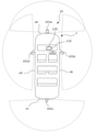
基準点の3次元座標及び当該基準点の画素座標の組を得るために、特定模様の校正指標が一般的に用いられる。校正指標の例を、図1に示す。図1の例では、格子状の模様が箱状の被写体の内側に一定間隔で配置されている。格子点、つまり、模様の角を基準点とし、基準点である格子点の3次元座標の設計値、又は、基準点の設置後に計測された基準点の3次元座標が保持される。さらに、基準点をカメラで撮影し、基準点である格子点の画素座標を画像処理で推定することで、基準点の3次元座標及び画素座標の組の情報が得られる。このような校正指標を用いる校正技術は、校正指標の利用が容易な、カメラ製造後の工場での校正などで有効である。また、3次元座標の精度の高い校正指標の利用、又は、画素座標の推定精度の高い画像処理と特定模様の校正指標とを導入することで、高精度な校正ができる。しかしながら、校正指標を備える設備等が必要になる課題がある。特に、カメラの撮影範囲が広いほど、撮影範囲を覆うためにより大きな校正指標が必要になる。 A calibration index of a specific pattern is generally used to obtain a set of three-dimensional coordinates of a reference point and pixel coordinates of the reference point. An example of the calibration index is shown in FIG. In the example of FIG. 1, grid-like patterns are arranged at regular intervals inside the box-shaped subject. The grid point, that is, the corner of the pattern is used as the reference point, and the design value of the three-dimensional coordinates of the grid point which is the reference point or the three-dimensional coordinates of the reference point measured after the reference point is set is held. Further, by photographing the reference point with a camera and estimating the pixel coordinates of the grid points which are the reference points by image processing, information on the three-dimensional coordinates of the reference point and the set of pixel coordinates can be obtained. A calibration technique using such a calibration index is effective for calibration in a factory after the camera is manufactured, where the calibration index can be easily used. Further, high-precision calibration can be performed by using a highly accurate calibration index of three-dimensional coordinates, or by introducing image processing with high estimation accuracy of pixel coordinates and a calibration index of a specific pattern. However, there is a problem that equipment or the like equipped with a calibration index is required. In particular, the wider the shooting range of the camera, the larger the calibration index is required to cover the shooting range.
また、カメラ校正は、製造時の校正のほかに、カメラを搭載する装置が稼動している状態で、経年変化、外力による変形又は温度変化等の影響によって、カメラパラメタセットが変わってしまった場合にも必要になる。自動車の安全運転支援システム及び監視カメラシステムなどにおいては、校正方法は、校正指標を備える設備等が不要であり、且つ、人手による操作が不要であることが望ましい。つまり、自己校正による校正方法が望ましい。ここで、カメラを備えるシステムがカメラパラメタセットを自動で更新することを自己校正と呼ぶ。 In addition to the calibration at the time of manufacture, the camera calibration is when the camera parameter set has changed due to the effects of aging, deformation due to external force, temperature change, etc. while the device on which the camera is mounted is operating. Is also needed. In a safe driving support system and a surveillance camera system of an automobile, it is desirable that the calibration method does not require equipment having a calibration index and does not require manual operation. That is, a calibration method by self-calibration is desirable. Here, the automatic update of the camera parameter set by the system equipped with the camera is called self-calibration.
特許文献2には、車両に設置されたステレオカメラをシステムが自動で校正する自己校正技術が開示されている。特許文献2の技術では、格子等の特定模様の校正指標を用いる代わりに、カメラの視野内にある静止物が校正目標として記憶され、カメラ視野内での校正目標の位置が変わった場合に、校正目標の3次元座標の情報を用いて、カメラの自己校正が行われる。
しかしながら、従来の校正技術では、校正目標の3次元座標は事前に得られており変化しないと仮定しているため、校正目標の3次元座標が経年変化、外力又は温度変化等の影響で変化した場合に、正しく校正できないという課題がある。そこで、本発明者らは、校正指標及び校正基準点の3次元座標が事前に与えられることなく、カメラの校正を可能にする技術を、下記のように創案した。 However, in the conventional calibration technique, since it is assumed that the three-dimensional coordinates of the calibration target are obtained in advance and do not change, the three-dimensional coordinates of the calibration target change due to the influence of aging, external force, temperature change, etc. In some cases, there is a problem that calibration cannot be performed correctly. Therefore, the present inventors have devised a technique that enables calibration of a camera without giving a calibration index and three-dimensional coordinates of a calibration reference point in advance as follows.
本開示の一態様に係るカメラパラメタセット算出装置は、複数のカメラで撮影された画像と前記複数のカメラのカメラパラメタセットとを用いて、カメラパラメタセットを算出する少なくとも1つの制御回路を備え、前記少なくとも1つの制御回路は、(a1)前記複数のカメラの第1カメラで撮影された第1画像と、前記複数のカメラの第2カメラで撮影された第2画像とを取得し、(a2)前記第1カメラの1つ以上のカメラパラメタを含む第1カメラパラメタセットと、前記第2カメラの1つ以上のカメラパラメタを含む第2カメラパラメタセットとを取得し、(a3)前記第1画像、前記第2画像、前記第1カメラパラメタセット及び前記第2カメラパラメタセットに基づいて、前記第1画像及び前記第2画像における被写体が部分的に重複して映し出される重複領域上の3次元座標を複数算出し、(a4)前記第1カメラパラメタセットに基づいて前記複数の3次元座標を前記第1画像に投影した複数の第1画素座標を決定し、前記第2カメラパラメタセットに基づいて前記複数の3次元座標を前記第2画像に投影した複数の第2画素座標を決定し、(a5)前記第1画像における前記複数の第1画素座標での複数の画素値と前記第2画像における前記複数の第2画素座標での複数の画素値とに基づいて評価値を算出し、(a6)前記評価値に基づいて、前記第1カメラパラメタセット及び前記第2カメラパラメタセットを更新し、(a7)更新された前記第1カメラパラメタセット及び前記第2カメラパラメタセットを出力する。 The camera parameter set calculation device according to one aspect of the present disclosure includes at least one control circuit for calculating a camera parameter set using images taken by a plurality of cameras and camera parameter sets of the plurality of cameras. The at least one control circuit acquires (a1) a first image taken by the first camera of the plurality of cameras and a second image taken by the second camera of the plurality of cameras, and (a2). ) The first camera parameter set including one or more camera parameters of the first camera and the second camera parameter set including one or more camera parameters of the second camera are acquired, and (a3) the first camera. Based on the image, the second image, the first camera parameter set, and the second camera parameter set, three dimensions on the overlapping region where the subjects in the first image and the second image are partially overlapped and projected. A plurality of coordinates are calculated, and (a4) a plurality of first pixel coordinates obtained by projecting the plurality of three-dimensional coordinates onto the first image are determined based on the first camera parameter set, and based on the second camera parameter set. The plurality of second pixel coordinates obtained by projecting the plurality of three-dimensional coordinates onto the second image are determined, and (a5) the plurality of pixel values at the plurality of first pixel coordinates in the first image and the second. The evaluation value is calculated based on the plurality of pixel values at the plurality of second pixel coordinates in the image, and (a6) the first camera parameter set and the second camera parameter set are updated based on the evaluation value. Then, (a7) the updated first camera parameter set and the second camera parameter set are output.
上記態様によれば、撮影画像に部分的な重複領域がある第1カメラ及び第2カメラについて、評価値に基づいたカメラパラメタセットの算出が可能である。よって、第1カメラ及び第2カメラが互いに離れていても、それぞれの向きが互いに異なっていても、カメラパラメタセットの算出が可能である。なお、評価値の算出に用いられる画素座標に対応する重複領域は、第1画像及び第2画像から抽出され、座標等が既知である予め設定された基準ではない。このため、カメラパラメタセットの算出過程における3次元座標と画素座標との対応付けに、既知の基準点を含む校正指標を備える設備が不要である。言い換えると、本態様は、事前に得た基準点の3次元座標を用いないため、経年変化、外力、温度変化等の影響による基準点の変化とは無関係に、カメラを正しく自己校正できる。 According to the above aspect, it is possible to calculate the camera parameter set based on the evaluation value for the first camera and the second camera having a partially overlapping region in the captured image. Therefore, it is possible to calculate the camera parameter set even if the first camera and the second camera are separated from each other or their directions are different from each other. The overlapping region corresponding to the pixel coordinates used for calculating the evaluation value is extracted from the first image and the second image, and is not a preset standard in which the coordinates and the like are known. Therefore, there is no need for equipment having a calibration index including a known reference point for associating the three-dimensional coordinates with the pixel coordinates in the calculation process of the camera parameter set. In other words, since this embodiment does not use the three-dimensional coordinates of the reference point obtained in advance, the camera can be correctly self-calibrated regardless of the change of the reference point due to the influence of secular variation, external force, temperature change, and the like.
なお、第1カメラパラメタセット及び第2カメラパラメタセットが正しい場合に、ある点の3次元座標に対応する第1画素座標での第1画像の画素値及び第2画素座標での第2画像の画素値は、互いに等しく、第1カメラパラメタセット又は第2カメラパラメタセットが正解値から離れるほど、つまり誤差を多く含むほど、第1画像の画素値と第2画像の画素値との間に差異が生じる。このため、第1カメラパラメタセット又は第2カメラパラメタセットが誤差を含む場合に、第1画像の画素値と第2画像の画素値との差異に基づいて、例えば、差異を最小にするように、第1カメラパラメタセット及び第2カメラパラメタセットを変更することで、正しいカメラパラメタセットを得ることができる。すなわち、第1及び第2カメラを校正することができる。 When the first camera parameter set and the second camera parameter set are correct, the pixel value of the first image at the first pixel coordinates corresponding to the three-dimensional coordinates of a certain point and the second image at the second pixel coordinates. The pixel values are equal to each other, and the farther the first camera parameter set or the second camera parameter set is from the correct answer value, that is, the more the error is included, the more the difference between the pixel value of the first image and the pixel value of the second image is. Occurs. Therefore, when the first camera parameter set or the second camera parameter set contains an error, the difference is minimized, for example, based on the difference between the pixel value of the first image and the pixel value of the second image. , The correct camera parameter set can be obtained by changing the first camera parameter set and the second camera parameter set. That is, the first and second cameras can be calibrated.
また、本開示の一態様に係るカメラパラメタセット算出装置において、前記第1画像及び前記第2画像は、(i)車両の前部に配置されたカメラで前記車両の前方を撮影した画像、及び前記車両の左部に配置されたカメラで前記車両の左方を撮影した画像の組み合わせ、(ii)車両の前部に配置されたカメラで前記車両の前方を撮影した画像、及び前記車両の右部に配置されたカメラで前記車両の右方を撮影した画像の組み合わせ、(iii)車両の後部に配置されたカメラで前記車両の後方を撮影した画像、及び前記車両の左部に配置されたカメラで前記車両の左方を撮影した画像の組み合わせ、(iv)車両の後部に配置されたカメラで前記車両の後方を撮影した画像、及び前記車両の右部に配置されたカメラで前記車両の右方を撮影した画像の組み合わせ、のうちのいずれかの組み合わせであってもよい。 Further, in the camera parameter set calculation device according to one aspect of the present disclosure, the first image and the second image are (i) an image of the front of the vehicle taken by a camera arranged at the front of the vehicle, and an image of the front of the vehicle. A combination of images taken from the left side of the vehicle by a camera placed on the left side of the vehicle, (ii) an image taken from the front of the vehicle by a camera placed on the front part of the vehicle, and the right side of the vehicle. A combination of images taken from the right side of the vehicle with a camera placed in the portion, (iii) an image taken from the rear of the vehicle with a camera placed at the rear of the vehicle, and an image taken at the left part of the vehicle. A combination of images taken from the left side of the vehicle with a camera, (iv) an image taken from the rear of the vehicle with a camera placed at the rear of the vehicle, and a camera placed at the right side of the vehicle of the vehicle. It may be any combination of images taken on the right side.
上記態様において、第1カメラ及び第2カメラは、異なる向きに指向されているが、撮影画像に部分的な重複領域があるように構成又は配置されることによって、カメラパラメタセットの算出を可能にする。 In the above embodiment, the first camera and the second camera are oriented in different directions, but the camera parameter set can be calculated by being configured or arranged so that the captured image has a partially overlapping region. do.
また、本開示の一態様に係るカメラパラメタセット算出装置において、前記少なくとも1つの制御回路は、処理(a5)では、前記第1画素座標における前記第1画像の画素値と前記第2画素座標における前記第2画像の画素値との差異に基づいて前記評価値を算出してもよい。 Further, in the camera parameter set calculation device according to one aspect of the present disclosure, in the process (a5), the at least one control circuit is in the pixel value of the first image and the second pixel coordinate in the first pixel coordinate. The evaluation value may be calculated based on the difference from the pixel value of the second image.
上記態様によれば、第1画素座標での第1画像の画素値と第2画素座標での第2画像の画素値との間に差異がある場合、第1カメラパラメタセット及び第2カメラパラメタセットに、真値に対する誤差があると判定することが可能である。よって、第1カメラパラメタセット及び第2カメラパラメタセットの良否の判定が容易である。さらに、例えば、上記差異を小さくするように、第1カメラパラメタセット及び第2カメラパラメタセットを変更つまり更新することによって、第1カメラパラメタセット及び第2カメラパラメタセットを適切にすることが可能である。 According to the above aspect, when there is a difference between the pixel value of the first image at the first pixel coordinate and the pixel value of the second image at the second pixel coordinate, the first camera parameter set and the second camera parameter It is possible to determine that the set has an error with respect to the true value. Therefore, it is easy to determine the quality of the first camera parameter set and the second camera parameter set. Further, for example, by changing or updating the first camera parameter set and the second camera parameter set so as to reduce the above difference, it is possible to make the first camera parameter set and the second camera parameter set appropriate. be.
また、本開示の一態様に係るカメラパラメタセット算出装置において、前記少なくとも1つの制御回路は、前記複数のカメラの第3カメラで撮影された第3画像と、前記第3カメラの第3カメラパラメタセットとをさらに取得し、前記第1画像、前記第2画像及び前記第3画像から、2つの画像により構成される複数の組を決定し、前記複数の組それぞれに含まれる2つの画像に対して、処理(a3)~処理(a5)を順次行ってもよい。 Further, in the camera parameter set calculation device according to one aspect of the present disclosure, the at least one control circuit includes a third image taken by the third camera of the plurality of cameras and a third camera parameter of the third camera. A set is further acquired, and a plurality of sets composed of the two images are determined from the first image, the second image, and the third image, and for the two images included in each of the plurality of sets. Then, the processing (a3) to the processing (a5) may be sequentially performed.
上記態様によれば、複数のカメラの画像を用いることによって、重複領域の面積の増大が見込める。よって、校正精度の向上が見込める。2つの画像を用いて評価値の算出まで完了することよって、他の画像の干渉を受けない評価値が算出される。これよって、2つの画像から得られる結果が、適正か否かを判別することができる。例えば、判別結果に基づき、カメラパラメタセットの変更方法を検討することができる。つまり、カメラの視野の部分的な領域での校正が可能になる。 According to the above aspect, the area of the overlapping region can be expected to increase by using the images of a plurality of cameras. Therefore, the calibration accuracy can be expected to be improved. By completing the calculation of the evaluation value using the two images, the evaluation value that is not interfered with by the other images is calculated. Thereby, it can be determined whether or not the result obtained from the two images is appropriate. For example, a method of changing the camera parameter set can be examined based on the discrimination result. That is, it is possible to calibrate a partial area of the field of view of the camera.
また、本開示の一態様に係るカメラパラメタセット算出装置において、前記少なくとも1つの制御回路は、前記複数のカメラの第3カメラで撮影された第3画像と、前記第3カメラの第3カメラパラメタセットとをさらに取得し、前記第1画像、前記第2画像及び前記第3画像から、2つの画像により構成される複数の組を決定し、前記複数の組それぞれに含まれる2つの画像に対して、処理(a3)~処理(a5)を行って得られる画素値を用いて、前記評価値を算出してもよい。 Further, in the camera parameter set calculation device according to one aspect of the present disclosure, the at least one control circuit includes a third image taken by the third camera of the plurality of cameras and a third camera parameter of the third camera. A set is further acquired, and a plurality of sets composed of the two images are determined from the first image, the second image, and the third image, and for the two images included in each of the plurality of sets. Then, the evaluation value may be calculated using the pixel values obtained by performing the processing (a3) to the processing (a5).
上記態様によれば、複数のカメラの画像を用いることによって、重複領域の面積の増大が見込める。よって、校正精度の向上が見込める。複数の組それぞれで算出される画素値を、評価値の算出に適用することよって、1つのカメラについて複数の重複領域を用いた校正が可能になる。これにより、校正に利用できる画像の面積が増え、カメラの視野の広い領域にわたる全体的な校正が可能になる。また、複数の組それぞれで算出される画素値を、評価値の算出に適用することよって、第1カメラ、第2カメラ及び第3カメラの全体的な校正が可能になる。 According to the above aspect, the area of the overlapping region can be expected to increase by using the images of a plurality of cameras. Therefore, the calibration accuracy can be expected to be improved. By applying the pixel values calculated for each of the plurality of sets to the calculation of the evaluation values, it is possible to calibrate one camera using a plurality of overlapping regions. This increases the area of the image that can be used for calibration and allows for overall calibration over a wide area of the camera's field of view. Further, by applying the pixel values calculated for each of the plurality of sets to the calculation of the evaluation values, the overall calibration of the first camera, the second camera, and the third camera becomes possible.
また、本開示の一態様に係るカメラパラメタセット算出装置において、前記第1画像及び前記第2画像は、被写体の一部が重複して映る第1重複領域を含み、前記第2画像及び前記第3画像は、被写体の一部が重複して映る第2重複領域を含み、前記第1重複領域と前記第2重複領域とは、重複しなくてもよい。 Further, in the camera parameter set calculation device according to one aspect of the present disclosure, the first image and the second image include a first overlapping region in which a part of the subject is overlapped, and the second image and the second image are included. The three images include a second overlapping region in which a part of the subject is overlapped, and the first overlapping region and the second overlapping region may not overlap.
上記態様によれば、重複領域において、3つ以上の画像が重複しない。これにより、重複領域の面積の増大が可能である。よって、画像における校正対象の領域の増大が可能になり、画像の広い領域に対する校正が可能になる。従って、校正精度が向上する。 According to the above aspect, three or more images do not overlap in the overlapping region. This makes it possible to increase the area of the overlapping area. Therefore, it is possible to increase the area to be calibrated in the image, and it is possible to calibrate a wide area of the image. Therefore, the calibration accuracy is improved.
また、本開示の一態様に係るカメラパラメタセット算出装置において、前記第1画像及び前記第2画像はそれぞれ、光軸中心での光軸の方向が互いに交差する方向であるように配置された前記第1カメラ及前記第2カメラで撮影された画像であってもよい。 Further, in the camera parameter set calculation device according to one aspect of the present disclosure, the first image and the second image are arranged so that the directions of the optical axes at the center of the optical axis intersect each other. Images taken by the first camera and the second camera may be used.
本開示の一態様に係るカメラパラメタセット算出方法は、(a1)複数のカメラの第1カメラで撮影された第1画像と、前記複数のカメラの第2カメラで撮影された第2画像とを取得し、(a2)前記第1カメラの1つ以上のカメラパラメタを含む第1カメラパラメタセットと、前記第2カメラの1つ以上のカメラパラメタを含む第2カメラパラメタセットとを取得し、(a3)前記第1画像、前記第2画像、前記第1カメラパラメタセット及び前記第2カメラパラメタセットに基づいて、前記第1画像及び前記第2画像における被写体が部分的に重複して映し出される重複領域上の3次元座標を複数算出し、(a4)前記第1カメラパラメタセットに基づいて前記複数の3次元座標を前記第1画像に投影した複数の第1画素座標を決定し、前記第2カメラパラメタセットに基づいて前記複数の3次元座標を前記第2画像に投影した複数の第2画素座標を決定し、(a5)前記第1画像における前記複数の第1画素座標での複数の画素値と前記第2画像における前記複数の第2画素座標での複数の画素値とに基づいて評価値を算出し、(a6)前記評価値に基づいて、前記第1カメラパラメタセット及び前記第2カメラパラメタセットを更新し、(a7)更新された前記第1カメラパラメタセット及び前記第2カメラパラメタセットを出力し、処理(a1)~処理(a7)の少なくとも1つがプロセッサによって実行される。上記態様によれば、本開示の一態様に係るカメラパラメタセット算出装置と同様の効果が得られる。 The camera parameter set calculation method according to one aspect of the present disclosure is (a1) a first image taken by the first camera of a plurality of cameras and a second image taken by the second camera of the plurality of cameras. (A2) The first camera parameter set including one or more camera parameters of the first camera and the second camera parameter set including one or more camera parameters of the second camera are acquired, and (a2) is acquired. a3) Overlap in which the subjects in the first image and the second image are partially overlapped based on the first image, the second image, the first camera parameter set, and the second camera parameter set. A plurality of three-dimensional coordinates on the region are calculated, and (a4) a plurality of first pixel coordinates obtained by projecting the plurality of three-dimensional coordinates onto the first image are determined based on the first camera parameter set, and the second Based on the camera parameter set, the plurality of second pixel coordinates obtained by projecting the plurality of three-dimensional coordinates onto the second image are determined, and (a5) the plurality of pixels at the plurality of first pixel coordinates in the first image. The evaluation value is calculated based on the value and the plurality of pixel values at the plurality of second pixel coordinates in the second image, and (a6) the first camera parameter set and the second camera based on the evaluation value. The camera parameter set is updated, (a7) the updated first camera parameter set and the second camera parameter set are output, and at least one of the processes (a1) to (a7) is executed by the processor. According to the above aspect, the same effect as that of the camera parameter set calculation device according to one aspect of the present disclosure can be obtained.
また、本開示の一態様に係るカメラパラメタセット算出方法において、前記第1画像及び前記第2画像は、(i)車両の前部に配置されたカメラで前記車両の前方を撮影した画像、及び前記車両の左部に配置されたカメラで前記車両の左方を撮影した画像の組み合わせ、(ii)車両の前部に配置されたカメラで前記車両の前方を撮影した画像、及び前記車両の右部に配置されたカメラで前記車両の右方を撮影した画像の組み合わせ、(iii)車両の後部に配置されたカメラで前記車両の後方を撮影した画像、及び前記車両の左部に配置されたカメラで前記車両の左方を撮影した画像の組み合わせ、(iv)車両の後部に配置されたカメラで前記車両の後方を撮影した画像、及び前記車両の右部に配置されたカメラで前記車両の右方を撮影した画像の組み合わせ、のうちのいずれかの組み合わせであってもよい。 Further, in the camera parameter set calculation method according to one aspect of the present disclosure, the first image and the second image are (i) an image of the front of the vehicle taken by a camera arranged at the front of the vehicle, and an image of the front of the vehicle. A combination of images taken from the left side of the vehicle by a camera placed on the left side of the vehicle, (ii) an image taken from the front of the vehicle by a camera placed on the front part of the vehicle, and the right side of the vehicle. A combination of images taken from the right side of the vehicle with a camera placed in the portion, (iii) an image taken from the rear of the vehicle with a camera placed at the rear of the vehicle, and an image taken at the left part of the vehicle. A combination of images taken from the left side of the vehicle with a camera, (iv) an image taken from the rear of the vehicle with a camera placed at the rear of the vehicle, and a camera placed at the right side of the vehicle of the vehicle. It may be any combination of images taken on the right side.
また、本開示の一態様に係るカメラパラメタセット算出方法において、処理(a5)では、前記第1画素座標における前記第1画像の画素値と前記第2画素座標における前記第2画像の画素値との差異に基づいて前記評価値を算出してもよい。 Further, in the camera parameter set calculation method according to one aspect of the present disclosure, in the process (a5), the pixel value of the first image in the first pixel coordinates and the pixel value of the second image in the second pixel coordinates are used. The evaluation value may be calculated based on the difference between the above.
また、本開示の一態様に係るカメラパラメタセット算出方法において、前記複数のカメラの第3カメラで撮影された第3画像と、前記第3カメラの第3カメラパラメタセットとをさらに取得し、前記第1画像、前記第2画像及び前記第3画像から、2つの画像により構成される複数の組を決定し、前記複数の組それぞれに含まれる2つの画像に対して、処理(a3)~処理(a5)を順次行ってもよい。 Further, in the camera parameter set calculation method according to one aspect of the present disclosure, the third image taken by the third camera of the plurality of cameras and the third camera parameter set of the third camera are further acquired, and the said. From the first image, the second image, and the third image, a plurality of sets composed of the two images are determined, and the two images included in each of the plurality of sets are processed (a3) to processed. (A5) may be sequentially performed.
また、本開示の一態様に係るカメラパラメタセット算出方法において、前記複数のカメラの第3カメラで撮影された第3画像と、前記第3カメラの第3カメラパラメタセットとをさらに取得し、前記第1画像、前記第2画像及び前記第3画像から、2つの画像により構成される複数の組を決定し、前記複数の組それぞれに含まれる2つの画像に対して、処理(a3)~処理(a5)を行って得られる画素値を用いて、前記評価値を算出してもよい。 Further, in the camera parameter set calculation method according to one aspect of the present disclosure, the third image taken by the third camera of the plurality of cameras and the third camera parameter set of the third camera are further acquired, and the said. From the first image, the second image, and the third image, a plurality of sets composed of the two images are determined, and the two images included in each of the plurality of sets are processed (a3) to processed. The evaluation value may be calculated using the pixel value obtained by performing (a5).
また、本開示の一態様に係るカメラパラメタセット算出方法において、前記第1画像及び前記第2画像は、被写体の一部が重複して映る第1重複領域を含み、前記第2画像及び前記第3画像は、被写体の一部が重複して映る第2重複領域を含み、前記第1重複領域と前記第2重複領域とは、重複しなくてもよい。 Further, in the camera parameter set calculation method according to one aspect of the present disclosure, the first image and the second image include a first overlapping region in which a part of the subject is overlapped, and the second image and the second image are included. The three images include a second overlapping region in which a part of the subject is overlapped, and the first overlapping region and the second overlapping region may not overlap.
また、本開示の一態様に係るカメラパラメタセット算出方法において、前記第1画像及び前記第2画像はそれぞれ、光軸中心での光軸の方向が互いに交差する方向であるように配置された前記第1カメラ及前記第2カメラで撮影された画像であってもよい。 Further, in the camera parameter set calculation method according to one aspect of the present disclosure, the first image and the second image are arranged so that the directions of the optical axes at the center of the optical axis intersect each other. Images taken by the first camera and the second camera may be used.
本開示の一態様に係るプログラムは、コンピュータに実行させるプログラムであって、(a1)複数のカメラの第1カメラで撮影された第1画像と、前記複数のカメラの第2カメラで撮影された第2画像とを取得し、(a2)前記第1カメラの1つ以上のカメラパラメタを含む第1カメラパラメタセットと、前記第2カメラの1つ以上のカメラパラメタを含む第2カメラパラメタセットとを取得し、(a3)前記第1画像、前記第2画像、前記第1カメラパラメタセット及び前記第2カメラパラメタセットに基づいて、前記第1画像及び前記第2画像における被写体が部分的に重複して映し出される重複領域上の3次元座標を複数算出し、(a4)前記第1カメラパラメタセットに基づいて前記複数の3次元座標を前記第1画像に投影した複数の第1画素座標を決定し、前記第2カメラパラメタセットに基づいて前記複数の3次元座標を前記第2画像に投影した複数の第2画素座標を決定し、(a5)前記第1画像における前記複数の第1画素座標での複数の画素値と前記第2画像における前記複数の第2画素座標での複数の画素値とに基づいて評価値を算出し、(a6)前記評価値に基づいて、前記第1カメラパラメタセット及び前記第2カメラパラメタセットを更新し、(a7)更新された前記第1カメラパラメタセット及び前記第2カメラパラメタセットを出力することを前記コンピュータに実行させる。上記態様によれば、本開示の一態様に係るカメラパラメタセット算出装置と同様の効果が得られる。 The program according to one aspect of the present disclosure is a program to be executed by a computer, and is (a1) a first image taken by a first camera of a plurality of cameras and a second camera of the plurality of cameras. The second image is acquired, and (a2) a first camera parameter set including one or more camera parameters of the first camera and a second camera parameter set including one or more camera parameters of the second camera. (A3) The subjects in the first image and the second image partially overlap based on the first image, the second image, the first camera parameter set, and the second camera parameter set. A plurality of three-dimensional coordinates on the overlapping region projected in the above are calculated, and (a4) a plurality of first pixel coordinates obtained by projecting the plurality of three-dimensional coordinates onto the first image are determined based on the first camera parameter set. Then, based on the second camera parameter set, the plurality of second pixel coordinates obtained by projecting the plurality of three-dimensional coordinates onto the second image are determined, and (a5) the plurality of first pixel coordinates in the first image. The evaluation value is calculated based on the plurality of pixel values in the above and the plurality of pixel values at the plurality of second pixel coordinates in the second image, and (a6) the first camera parameter is calculated based on the evaluation value. The set and the second camera parameter set are updated, and (a7) the computer is made to output the updated first camera parameter set and the second camera parameter set. According to the above aspect, the same effect as that of the camera parameter set calculation device according to one aspect of the present disclosure can be obtained.
また、本開示の一態様に係るプログラムにおいて、前記第1画像及び前記第2画像は、(i)車両の前部に配置されたカメラで前記車両の前方を撮影した画像、及び前記車両の左部に配置されたカメラで前記車両の左方を撮影した画像の組み合わせ、(ii)車両の前部に配置されたカメラで前記車両の前方を撮影した画像、及び前記車両の右部に配置されたカメラで前記車両の右方を撮影した画像の組み合わせ、(iii)車両の後部に配置されたカメラで前記車両の後方を撮影した画像、及び前記車両の左部に配置されたカメラで前記車両の左方を撮影した画像の組み合わせ、(iv)車両の後部に配置されたカメラで前記車両の後方を撮影した画像、及び前記車両の右部に配置されたカメラで前記車両の右方を撮影した画像の組み合わせ、のうちのいずれかの組み合わせであってもよい。 Further, in the program according to one aspect of the present disclosure, the first image and the second image are (i) an image of the front of the vehicle taken by a camera arranged at the front of the vehicle, and the left of the vehicle. A combination of images taken from the left side of the vehicle by a camera arranged in a section, (ii) an image taken from the front of the vehicle by a camera arranged in the front part of the vehicle, and arranged in the right part of the vehicle. A combination of images taken from the right side of the vehicle with a camera, (iii) an image taken from the rear of the vehicle with a camera placed at the rear of the vehicle, and a camera placed at the left side of the vehicle. A combination of images taken from the left side of the vehicle, (iv) an image taken from the rear of the vehicle with a camera placed at the rear of the vehicle, and a right side of the vehicle taken with a camera placed at the right side of the vehicle. It may be any combination of the images that have been created.
また、本開示の一態様に係るプログラムにおいて、処理(a5)では、前記第1画素座標における前記第1画像の画素値と前記第2画素座標における前記第2画像の画素値との差異に基づいて前記評価値を算出してもよい。 Further, in the program according to one aspect of the present disclosure, in the process (a5), the process (a5) is based on the difference between the pixel value of the first image in the first pixel coordinates and the pixel value of the second image in the second pixel coordinates. The evaluation value may be calculated.
また、本開示の一態様に係るプログラムにおいて、前記複数のカメラの第3カメラで撮影された第3画像と、前記第3カメラの第3カメラパラメタセットとをさらに取得し、前記第1画像、前記第2画像及び前記第3画像から、2つの画像により構成される複数の組を決定し、前記複数の組それぞれに含まれる2つの画像に対して、処理(a3)~処理(a5)を順次行ってもよい。 Further, in the program according to one aspect of the present disclosure, the third image taken by the third camera of the plurality of cameras and the third camera parameter set of the third camera are further acquired, and the first image, From the second image and the third image, a plurality of sets composed of the two images are determined, and processing (a3) to processing (a5) are performed on the two images included in each of the plurality of sets. It may be done sequentially.
また、本開示の一態様に係るプログラムにおいて、前記複数のカメラの第3カメラで撮影された第3画像と、前記第3カメラの第3カメラパラメタセットとをさらに取得し、前記第1画像、前記第2画像及び前記第3画像から、2つの画像により構成される複数の組を決定し、前記複数の組それぞれに含まれる2つの画像に対して、処理(a3)~処理(a5)を行って得られる画素値を用いて、前記評価値を算出してもよい。 Further, in the program according to one aspect of the present disclosure, the third image taken by the third camera of the plurality of cameras and the third camera parameter set of the third camera are further acquired, and the first image, From the second image and the third image, a plurality of sets composed of the two images are determined, and processing (a3) to processing (a5) are performed on the two images included in each of the plurality of sets. The evaluation value may be calculated by using the pixel value obtained by the operation.
また、本開示の一態様に係るプログラムにおいて、前記第1画像及び前記第2画像は、被写体の一部が重複して映る第1重複領域を含み、前記第2画像及び前記第3画像は、被写体の一部が重複して映る第2重複領域を含み、前記第1重複領域と前記第2重複領域とは、重複しなくてもよい。 Further, in the program according to one aspect of the present disclosure, the first image and the second image include a first overlapping region in which a part of the subject is overlapped, and the second image and the third image are The first overlapping area and the second overlapping area may not overlap with each other, including the second overlapping area in which a part of the subject is overlapped.
また、本開示の一態様に係るプログラムにおいて、前記第1画像及び前記第2画像はそれぞれ、光軸中心での光軸の方向が互いに交差する方向であるように配置された前記第1カメラ及前記第2カメラで撮影された画像であってもよい。 Further, in the program according to one aspect of the present disclosure, the first image and the second image are respectively arranged so that the directions of the optical axes at the center of the optical axis intersect with each other. It may be an image taken by the second camera.
なお、上記の全般的又は具体的な態様は、システム、装置、方法、集積回路、コンピュータプログラム又はコンピュータ読み取り可能な記録ディスク等の記録媒体で実現されてもよく、システム、装置、方法、集積回路、コンピュータプログラム及び記録媒体の任意な組み合わせで実現されてもよい。コンピュータ読み取り可能な記録媒体は、例えばCD-ROM等の不揮発性の記録媒体を含む。 It should be noted that the above general or specific embodiment may be realized by a recording medium such as a system, an apparatus, a method, an integrated circuit, a computer program or a computer-readable recording disk, and the system, the apparatus, the method, the integrated circuit. , Computer programs and any combination of recording media. Computer-readable recording media include non-volatile recording media such as CD-ROMs.
以下、実施の形態に係るカメラパラメタセット算出装置等を、図面を参照しながら説明する。なお、以下で説明される実施の形態は、包括的又は具体的な例を示すものである。以下の実施の形態で示される数値、形状、材料、構成要素、構成要素の配置位置及び接続形態、ステップ(工程)、並びにステップの順序等は、一例であり、本開示を限定する主旨ではない。また、以下の実施の形態における構成要素のうち、最上位概念を示す独立請求項に記載されていない構成要素については、任意の構成要素として説明される。また、以下の実施の形態の説明において、略平行、略直交のような「略」を伴った表現が、用いられる場合がある。例えば、略平行とは、完全に平行であることを意味するだけでなく、実質的に平行である、すなわち、例えば数%程度の差異を含むことも意味する。他の「略」を伴った表現についても同様である。 Hereinafter, the camera parameter set calculation device and the like according to the embodiment will be described with reference to the drawings. The embodiments described below are comprehensive or specific examples. The numerical values, shapes, materials, components, arrangement positions and connection forms of the components, steps (processes), order of steps, etc. shown in the following embodiments are examples, and are not intended to limit the present disclosure. .. Further, among the components in the following embodiments, the components not described in the independent claim indicating the highest level concept are described as arbitrary components. Further, in the following description of the embodiment, expressions with "abbreviations" such as substantially parallel and substantially orthogonal may be used. For example, substantially parallel means not only completely parallel, but also substantially parallel, that is, including a difference of, for example, about several percent. The same applies to other expressions with "abbreviations".
[実施の形態]
[1.車載カメラシステムの構成]
本開示の実施の形態に係るカメラパラメタセット算出装置111を備える車載カメラシステム10を説明する。これに限定するものではないが、本実施の形態では、車載カメラシステム10は、移動体の一例である車両に搭載されるカメラシステムであるとして、説明する。図2を参照すると、実施の形態に係るカメラパラメタセット算出装置111を備える車載カメラシステム10の機能的な構成を示すブロック図が示されている。図2に示されるように、車載カメラシステム10は、撮像部100と、画像処理部110と、ディスプレイ120とを備える。なお、車載カメラシステム10が搭載される対象は、車両、つまり乗り物であってもよい。例えば、上記対象は、自動車、及び、自動車以外の車両であってもよく、船舶又は航空機であってもよい。自動車以外の車両は、トラック、バス、二輪車、搬送車、鉄道、建設機械、荷役機械等であってもよい。また、車載カメラシステム10が搭載される対象は、利用者が遠隔操作する車両またはロボットであってもよい。
[Embodiment]
[1. In-vehicle camera system configuration]
An in-
撮像部100は、画像を撮影して取得し、画像処理部110に出力する。撮像部100は、2つ以上のカメラ101を備え、本実施の形態では、4つのカメラ101a、101b、101c及び101dを備える。例えば、図3には、実施の形態に係る車載カメラシステム10の車両vへの搭載例が示されている。これに限定するものではないが、本実施の形態では、4つのカメラ101a~101dはそれぞれ、1つの車両vの前部va、右側部vb、後部vc及び左側部vdに配置され、当該車両vの前方、右側方、後方及び左側方を撮影する。なお、車両vの右側とは、前方に対する右側である。よって、4つのカメラ101a~101dは、車両vの周囲を包囲するように配置されている。これに限定されるものではないが、本実施の形態では、4つのカメラ101a~101dは、互いに同期して、画像を撮影して出力する。また、画像処理部110及びディスプレイ120はそれぞれ、例えばドライバから見える車室内に設置される。
The
4つのカメラ101a~101dは、互いに異なる向きに指向されている。本実施の形態では、車両vの水平方向の周囲に沿って隣り合うカメラ101a~101dは、互いの光軸中心での光軸の方向が交差するような向きに向けられている。具体的には、カメラ101a~101dは、外方へ放射状に方向付けられている。広範囲を撮影するために、4つのカメラ101a~101dの各々は、視野角が概ね180度の魚眼レンズを用いる。カメラ101a~101dはそれぞれ、図3に破線で示されるように、半球に近い円錐状の視野を有している。このため、車両vの水平方向の周囲に沿って隣り合うカメラの視野は、互いに部分的に重なり合う領域を有している。なお、本実施の形態では、2つのカメラの視野が重なり合うが、3つ以上のカメラの視野が重なり合わない。しかしながら、これに限定されず、3つ以上のカメラの視野が重なり合ってもよい。そして、このような4つのカメラ101a~101dは、車両vの水平方向の全周囲を同時に視野に含むことができる。
The four
本実施の形態では、車載カメラシステム10の撮像部100は、4つのカメラで構成されるとしたが、カメラの数量は4つに限定されるものではなく、2つ以上のカメラを有する構成であればよい。撮像部100は、例えば、図3のように前後左右に配置された4つのカメラを備える代わりに、車両vの後部及び左側部に配置された2つのカメラを備えてもよい。
In the present embodiment, the
図2及び図3を参照すると、画像処理部110は、撮像部100によって撮影された画像を処理し、その処理結果をディスプレイ120等に出力する。画像処理部110は、カメラパラメタセット算出装置111と、カメラパラメタ記憶部112と、画像生成部113とを備える。カメラパラメタセット算出装置111のことを、自己校正部とも呼ぶ。また、ディスプレイ120は、画像処理部110から出力された画像等を表示する。ディスプレイ120は、液晶パネル、有機又は無機EL(Electro Luminescence)等の表示パネルによって構成されてよい。なお、同様の構成要素を区別するために添え字a~dを用いるが、以下では、これらの構成要素を特に区別しない場合には、添え字を除いた符号のみを用いることがある。
Referring to FIGS. 2 and 3, the
車載カメラシステム10は、主に画像生成と、自己校正との2種類の動作をする。画像生成時、撮像部100は画像を撮影して画像処理部110に出力し、画像処理部110は、入力された画像から画像を生成して出力し、ディスプレイ120に表示する。自己校正時、撮像部100は画像を撮影して画像処理部110に出力し、画像処理部110のカメラパラメタセット算出装置111は、カメラパラメタ記憶部112に格納されているカメラパラメタセットを更新する。なお、画像生成と自己校正との2種類の動作は、同時に行われてもよく、別々に行われてもよい。
The in-
撮像部100は、視野角が概ね180度の魚眼レンズを有する4つのカメラ101a~101dで構成される。4つのカメラ101a~101dは、図3に示すように配置され、視野内の被写体をそれぞれ撮影して4つの画像を出力する(以降、この画像をカメラ画像とも呼ぶ)。4つのカメラ101a~101dは、隣り合うカメラ間で視野が部分的に重なるように配置されている。例えば、4つのカメラ101a~101dでは、水平方向で隣り合うカメラ間で互いの視野が部分的に重なる。具体的には、カメラ101a及び101bのペア、カメラ101b及び101cのペア、カメラ101c及び101dのペア、並びに、カメラ101d及び101aのペア内で視野が重なる。
The
上述したように、画像処理部110は、カメラパラメタセット算出装置111、カメラパラメタ記憶部112及び画像生成部113を備える。
As described above, the
カメラパラメタ記憶部112は、カメラ101a~101dそれぞれのカメラパラメタセットと、カメラ101a~101dそれぞれについてカメラ画像における撮像部100によって遮蔽された領域の情報である遮蔽情報とを少なくとも予め格納している。カメラ101a~101dそれぞれについての遮蔽情報は、カメラ画像に含まれる領域であって、撮像部100の部分が撮影された領域であると定義してもよい。カメラ101a~101dそれぞれのカメラパラメタセットは、各カメラの位置及び向き等の外部パラメタセットと、各カメラのレンズの歪及び焦点距離等の内部パラメタセットとを含み得る。
The camera
自己校正部でもあるカメラパラメタセット算出装置111は、4つのカメラ101a~101dによって撮影されたカメラ画像と、カメラパラメタ記憶部112に記憶されたカメラ101a~101dのカメラパラメタセットとを用いて、カメラパラメタ記憶部112のカメラパラメタセットを更新する。カメラパラメタ記憶部112に記憶されたカメラ101a~101dのカメラパラメタセットは、初期カメラパラメタセットとして用いられる。初期カメラパラメタセットは、カメラパラメタ記憶部112に既に記憶されているカメラ101a~101dのカメラパラメタセットであってよい。例えば、初期カメラパラメタセットは、カメラ101a~101dの設計時のカメラパラメタセットであってもよく、使用段階においてカメラ101a~101dに設定されているカメラパラメタセットであってもよい。
The camera parameter set
画像生成部113は、4つのカメラ101a~101dで撮影されたカメラ画像と、カメラパラメタ記憶部112に格納されたカメラパラメタセットとに基づいて、画像を生成して出力する。画像生成部113は、例えば、4台のカメラで撮影された画像に基づく合成画像を生成する。
The
図2の車載カメラシステム10のうちの画像処理部110を構成する各構成要素は、電子回路又は集積回路等のハードウェアで実現されてもよく、コンピュータ上で実行されるプログラム等のソフトウェアで実現されてもよい。
Each component constituting the
例えば、図4を参照すると、コンピュータによって構成された車載カメラシステム10のハードウェア構成の一例が示されている。車載カメラシステム10は、撮像部100と、画像処理部110に対応するコンピュータ300と、ディスプレイ120とを備える。車載カメラシステム10において、撮像部100は画像を撮影して出力し、コンピュータ300が画像処理部110として動作することにより、画像を生成して出力する。ディスプレイ120はコンピュータ300で生成された画像を表示する。
For example, with reference to FIG. 4, an example of the hardware configuration of the vehicle-mounted
コンピュータ300は、CPU(Central Processing Unit)301、ROM(Read Only Memory)302、RAM(Random Access Memory)303、HDD(Hard Disk Drive)304、ビデオ入力I/F(インタフェース)305及びビデオカード306を含む。
The
コンピュータ300を動作させるプログラムは、ROM302又はHDD304に予め保持されている。プログラムは、プロセッサであるCPU301によって、ROM302又はHDD304からRAM303に読み出されて展開される。
The program for operating the
CPU301は、RAM303に展開されたプログラム中のコード化された各命令を実行する。ビデオ入力I/F305は、プログラムの実行に応じて、撮像部100で撮影された画像を、RAM303へ取り込む。ビデオカード306は、プログラムの実行に応じて生成された画像を処理してディスプレイ120に出力し、ディスプレイ120がその画像を表示する。
The
なお、コンピュータプログラムは、半導体装置であるROM302又はHDD304に限られず、例えばCD―ROM等の記録媒体に格納されていてもよい。また、コンピュータプログラムは、有線ネットワーク、無線ネットワーク又は放送等を介して伝送され、コンピュータ300のRAM303に取り込まれてもよい。
The computer program is not limited to the
[2.車載カメラシステムの動作]
車載カメラシステム10の動作を説明する。具体的には、車載カメラシステム10における、画像生成時の動作と、自己校正時の動作とを、順に説明する。
[2. Operation of in-vehicle camera system]
The operation of the in-
[2-1.画像生成時の動作]
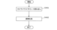
車載カメラシステム10における画像生成時の動作を、図5を用いて説明する。なお、図5は、車載カメラシステム10の画像処理部110における、画像生成時の動作の一例を表すフローチャートである。図5に示されるように、画像生成時の動作は、カメラパラメタセット読み出しのステップS401の処理と、画像生成のステップS402の処理とを含む。図5に示される各動作は、図4のコンピュータ300で実行されてもよい。
[2-1. Operation when generating an image]
The operation at the time of image generation in the in-
これに限定するものではないが、本実施の形態では、車載カメラシステム10が自動車に設置される例を説明する。具体的には、車載カメラシステム10は、自動車の前後左右を撮影して得られたカメラ画像を用いて、自動車の全周囲の画像を生成し、その結果を自動車内に設置されたディスプレイに表示し、それにより、利用者であるドライバに車両周辺の状況を提示する。
Although not limited to this, in the present embodiment, an example in which the in-
図6を参照すると、図3に示すカメラの設置状況において、4つのカメラ101a~101dで撮影される画像の例が示されている。カメラ101a~101dそれぞれの視野角は概ね180度である。隣り合う2つのカメラのカメラ画像中に、共通の被写体が映っている。
Referring to FIG. 6, an example of an image taken by four
コンピュータ300は、撮像部100の動作と並行して、予め定められたプログラムを実行することで、図5のステップS401及びS402の処理を行う。以降、コンピュータ300で実行されるステップS401及びS402の詳細な処理を、図2及び図5を用いて説明する。
The
ステップS401では、画像生成部113は、カメラパラメタ記憶部112から、カメラパラメタ記憶部112に予め格納されているカメラ101a~101dの内部パラメタセット及び外部パラメタセットを含むカメラパラメタセットを読み出す。カメラの外部パラメタセットMと3次元座標との関係、及び、カメラの内部パラメタセット(f,dpx,dpy,cu,cv)と3次元座標と画素座標との関係を下記の式1~式3に示す。
In step S401, the


ここで、上記の式1における外部パラメタセットMは、世界座標系とカメラ座標系との位置関係を表す外部パラメタセットであり、世界座標系の3次元座標(xw,yw,zw)を、カメラ座標系の3次元座標(xe,ye,ze)に変換する4×4の行列で表す。上記の式1及び式2に示すように、外部パラメタセットMは、世界座標系のX、Y及びZの各軸周りの回転角(Rx,Ry,Rz)と、X、Y及びZの各軸方向の平行移動量(tx,ty,tz)とを表す。上記の式3は、被写体上のある点のカメラ座標系における3次元座標(xe,ye,ze)と、カメラ画像に映った同じ点の画素座標(u,v)との関係を表している。内部パラメタセットのfはカメラの焦点距離であり、dpx及びdpyはそれぞれ、カメラの撮像素子のx方向及びy方向の画素サイズであり、(cu,cv)はカメラ座標系のze軸とカメラの撮像面との交点の画素座標である。なお、デジタル画像を「2次元の格子点(すなわち、画素座標)における値(すなわち画素値)」の集合と考えた場合に、画像上の画素の位置を2次元の画素座標で表現する。
Here, the external parameter set M in the
外部パラメタセットM及び内部パラメタセット(f,dpx,dpy,cu,cv)は、前述した従来技術のカメラ校正方法で予め求めておく。なお、dpx、dpy及びfの算出には、上記の式1~式3だけでは拘束条件が足りない。そこで、dpx、dpy及びfのいずれか1つは設計値が用いられ、残りの2つのパラメタが従来技術のカメラ校正方法で算出されてもよい。
The external parameter set M and the internal parameter set (f, dpx, dpy, cu, cv) are obtained in advance by the above-mentioned conventional camera calibration method. In addition, the constraint conditions are not sufficient for the calculation of dpx, dpy and f only by the
なお、上記の式3では、レンズの投影モデルとして透視投影モデル(ピンホールカメラモデルとも呼ばれる)を用いたが、これは投影モデルを限定するものではなく、等距離射影モデル、立体射影モデル及び等立体角射影モデル等の他の投影モデルを用いてもよい。例えば、等距離射影モデルの場合、上記の式3の内部パラメタセットの代わりに、下記の式4に示される内部パラメタセットを用いる。
In

以降、説明を簡単にするため、2つのカメラをカメラi及びjと記載する場合がある。この場合、カメラi及びjの位置関係を表す外部パラメタセットMi及びMjを、下記の式5のように示すことができる。
Hereinafter, for the sake of simplicity, the two cameras may be referred to as cameras i and j. In this case, the external parameter sets Mi and M j representing the positional relationship between the cameras i and j can be shown by the

また、例えば、カメラ101aの内部パラメタセット及び外部パラメタセットをまとめたカメラパラメタセットを、下記の式6に示すようなCaで表す。他のカメラ101b~101dそれぞれについても、内部パラメタセット及び外部パラメタセットをまとめたカメラパラメタセットを、Cb、Cc及びCdで同様に表すことができる。
Further, for example, the camera parameter set that summarizes the internal parameter set and the external parameter set of the
![]()
![]()
ステップS402では、画像生成部113は、4つのカメラ101a~101dそれぞれで撮影されたカメラ画像Ia~Idと、カメラ101a~101dそれぞれのカメラパラメタセットCa~Cdとを取得する。さらに、画像生成部113は、カメラ画像Ia~Idを、予め定めた空間モデルにマッピングする。本実施の形態では、予め定めた空間モデルとして、zw=0の平面モデルを用いるものとする。さらに、画像生成部113は、予め定めた仮想カメラのカメラパラメタセットCoを用いて、カメラ画像が投影された空間モデルを、仮想カメラから見た画像として生成する。本実施の形態では、予め定めた仮想カメラのカメラパラメタセットとして、図7に示すような車両の上方から車両の周辺を見下ろす配置の仮想カメラを適用する。なお、図7は、実施の形態における仮想カメラの配置例を示す模式的な図である。複数のカメラで撮影したカメラ画像から、空間モデルを用いて画像を生成する手法は、特許文献1等に詳しく記載されており、既知の技術であるため、本明細書ではこれ以上の詳細な説明を省略する。
In step S402, the
以上のように、コンピュータ300で実行されるステップS401及びS402の画像生成時の処理によって、画像処理部110は、撮像部100で撮像された4つのカメラ画像から、画像を生成して出力する。さらに、撮像部100及びコンピュータ300は、上記の処理を繰り返してもよい。
As described above, the
図8には、ステップS402の処理によって生成される画像の例が、示されている。図8を参照すると、自車両の周りの障害物、例えば、図8の例では、左方のトラック、右方のオートバイ及び後方の建物の方向及び距離を、運転者が容易に認知できる。 FIG. 8 shows an example of an image generated by the process of step S402. With reference to FIG. 8, the driver can easily recognize the direction and distance of obstacles around the own vehicle, for example, in the example of FIG. 8, the truck on the left, the motorcycle on the right, and the building behind.
以上のように、車載カメラシステム10の撮像部100、及び、コンピュータ300で実現される画像処理部110は、これらによる動作の結果、車体において異なる位置に配置された4つのカメラで撮影されたカメラ画像を用いて、仮想カメラから見た車体全周囲の画像を生成して表示することができる。その結果、車載カメラシステム10を搭載した自動車の運転者は、自動車の周囲の障害物等の3次元物体を容易に把握することができる。
As described above, the
[2-2.自己校正動作]
上述した車載カメラシステム10は、予め記録しておいたカメラパラメタセットを用いて画像を生成している。一方、カメラを製造した場合及び車両にカメラを設置した場合に、カメラパラメタセットは、組立て誤差に起因する差を設計値に対して有するため、カメラパラメタセットの推定、すなわち、カメラ校正が必要になる。また、組立て時にカメラ校正をした場合であっても、カメラの取り付け位置が、経年変化、外力又は温度変化等の影響を受けた場合に、変形等を生じて変わる場合がある。例えば、経年変化によって、カメラの取り付け位置が変化した場合に、経年変化前のカメラパラメタセットを用いて画像を生成すると、例えば、生成画像中の被写体の位置がずれるなど、生成画像が正しく生成されない。そのため、経年変化等でカメラパラメタが変化する場合にも、カメラの校正が必要になる。
[2-2. Self-calibration operation]
The vehicle-mounted
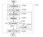
以下、車載カメラシステム10における自己校正時の動作について、図9及び図10を用いて説明する。なお、図9は、図2の車載カメラシステム10のカメラパラメタセット算出装置111の詳細な構成を示した機能的な構成図である。図10は、実施の形態に係る車載カメラシステム10の画像処理部110における自己校正処理S111の流れの一例を表すフローチャートである。自己校正処理S111は、自己校正動作の際の画像処理部110の処理であり、図4のコンピュータ300で実行される。
Hereinafter, the operation of the in-
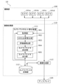
図9に示すように、自己校正処理S111を行う画像処理部110のカメラパラメタセット算出装置111は、取得部901と、3次元点群算出部902と、評価値算出部903と、カメラパラメタ決定部904と、カメラパラメタ出力部905とを含む。取得部901と、3次元点群算出部902と、評価値算出部903と、カメラパラメタ決定部904と、カメラパラメタ出力部905とによる各構成要素は、画像処理部110の各構成要素と同様の構成を有してもよい。
As shown in FIG. 9, the camera parameter set
取得部901は、カメラ101a~101dそれぞれによって撮影されたカメラ画像Ia~Idを、撮像部100から取得する。取得部901は、撮像部100又は画像処理部110等が有する図示しない半導体メモリ等の記憶装置に格納されたカメラ画像Ia~Idを取得してもよい。また、取得部901は、カメラ101a~101dに現在設定されているカメラパラメタで構成される初期カメラパラメタセットを、カメラパラメタ記憶部112から取得する。
The
3次元点群算出部902は、2つのカメラから取得した2つのカメラ画像間の対応点の組、すなわち、2つのカメラ画像のそれぞれに含まれる点であってかつ互いに対応する点の組を推定して抽出し、当該2つのカメラ画像それぞれにおける対応点の画素座標を算出する。2つのカメラ画像に同一の被写体が映っている場合、すなわち、一方のカメラ画像の被写体上の点が他方のカメラ画像にも映っている場合、これら2つの点のそれぞれを対応点と呼び、この2つの点の組を対応点の組と呼ぶ。対応点の組を推定するとは、具体的には、対応点の組のそれぞれの対応点の画素座標を算出することである。
The three-dimensional point
さらに、3次元点群算出部902は、対応点の組に含まれる対応点の画素座標及び2つのカメラの初期カメラパラメタセットに基づき、ステレオ測距技術を用いて、対応点の組に対する被写体上の点の3次元座標を算出する。なお、ステレオ測距技術は、ステレオ視とも呼ばれ、互いに異なる視点に位置し且つ視野が重複するように配置された2つのカメラを用いてカメラ画像が取得され、2つのカメラ画像のそれぞれに含まれる点であってかつ互いに対応する点の組、すなわち、対応点の組が推定され、対応点の組に含まれる2つの対応点と予め求めておいたカメラの位置及び向き等の情報とを用いて、対応点の組に対する被写体上の点の3次元座標が計算される。以降の説明において、3次元点群算出部902によって算出される3次元座標に対応する点を、測距点とも呼ぶ。
Further, the three-dimensional point
評価値算出部903は、測距点の3次元座標を対応点の組を推定した2つのカメラ画像それぞれに投影した点の画素値に基づき、カメラパラメタセットの評価値を算出する。以降の説明において、測距点を2つのカメラ画像に投影して得られる当該2つのカメラ画像上の点のそれぞれを、投影点と呼ぶ。カメラSで被写体を撮影して得たカメラ画像IS及びカメラTで被写体を撮影して得たカメラ画像ITに基づいた測距点を、カメラ画像ISに投影した投影点を第1投影点と呼び、同一の測距点をカメラ画像ITに投影した投影点を第2投影点と呼んでもよい。
The evaluation
カメラパラメタ決定部904は、評価値算出部903によって算出された評価値に基づき、現在、カメラ101a~101dに設定されているカメラパラメタセットを変更すべきか否かを判定する。カメラパラメタ決定部904は、判定結果に基づき、カメラパラメタセットを変更つまり更新する。このように、カメラパラメタ決定部904は、カメラパラメタセットを決定する。カメラパラメタ出力部905は、カメラパラメタ決定部904で決定されたカメラパラメタセットを取得し、カメラパラメタ記憶部112等に出力する。
The camera
図10に示すように、カメラパラメタセット算出装置111は、ステップS1001~S1007を含む自己校正処理S111を行うことによって、カメラ101a~101dに設定されているカメラパラメタのセット、つまり、初期カメラパラメタセットを校正する。自己校正処理S111において、カメラパラメタセット算出装置111は、自動的に校正処理を行う。カメラパラメタセット算出装置111は、スイッチ、タッチパッド、キーボード等の図示しない入力装置を介して、ユーザによって車載カメラシステム10へ校正指示が入力されると、カメラ101a~101dの自己校正処理を開始する。例えば、ユーザは、カメラ101a~101dの異常を確認した場合、校正指示を入力してもよく、カメラ101a~101dの製造完了後の工場出荷前に、校正指示を入力してもよい。また、カメラパラメタセット算出装置111は、予め設定された時期に、自己校正処理を自動的に開始してもよい。
As shown in FIG. 10, the camera parameter set
以下、4つのカメラのうち2つのカメラ101a及び101bについて、カメラ101a又は101bのカメラパラメタセットCa又はCbが誤差を含むことが、ユーザによって特定されている場合に、カメラパラメタセット算出装置111がカメラパラメタセットCa及びCbを校正する動作を説明する。
Hereinafter, when the user specifies that the camera parameter set Ca or Cb of the
例えば、図11には、図3に示すカメラの設置状態において、車両の前方及び右側方をそれぞれ撮影する2つのカメラ101a及び101bで撮影される画像の例が、示されている。2つのカメラ101a及び101bで撮影されたカメラ画像は、両方のカメラで重複して撮影される被写体が含まれる。この領域を、以降、重複撮影領域と呼ぶ。
For example, FIG. 11 shows an example of an image taken by two
ユーザによって車載カメラシステム10へ校正指示が入力されると、カメラパラメタセット算出装置111は、自己校正処理S111を開始する。そして、ステップS1001において、取得部901は、カメラ101a及び101bによって撮影されたカメラ画像Ia及びIbを取得する。さらに、ステップS1002において、取得部901は、カメラパラメタ記憶部112に予め格納されているカメラ101a及び101bそれぞれの初期カメラパラメタセットCa0及びCb0を読み込む。ここで、「予め」とは、「カメラパラメタセット算出装置111が自己校正処理を開始する前」であることを意味してもよい。
When the user inputs a calibration instruction to the vehicle-mounted
ステップS1003において、3次元点群算出部902は、取得されたカメラ101a及び101bのカメラ画像Ia及びIbを用いて、2つのカメラ画像Ia及びIb間でN個の対応点の組を推定し抽出する。さらに、3次元点群算出部902は、各対応点の組に含まれる2つの対応点の座標、つまり、カメラ画像Iaでの画素座標(uan,van)及びカメラ画像Ibでの画素座標(ubn,vbn)を算出して出力する。なお、nは、1~Nの値をとる。さらにまた、3次元点群算出部902は、カメラ画像Ia及びIbそれぞれでのN個の対応点組のそれぞれに含まれる2つの画素座標と、カメラ101a及び101bそれぞれのカメラパラメタセットCar及びCbrとを用いて、ステレオ測距技術により、N個の対応点の組に対する被写体上の点、すなわち、測距点の3次元座標(xarn,yarn,zarn)を算出して出力する。つまり、3次元点群算出部902は、N個の測距点の3次元座標を算出する。
In step S1003, the three-dimensional point
ステップS1003~S1006は、ステップS1005での判定結果に応じて、繰り返される。そして、繰り返しの度に、カメラ101a及び101bそれぞれのカメラパラメタセットが更新される。このため、r回目の繰り返し時のカメラ101a及び101bそれぞれのカメラパラメタセットを、カメラパラメタセットCar及びCbrと表す。初期カメラパラメタセットの場合、r=0である。
Steps S1003 to S1006 are repeated according to the determination result in step S1005. Then, each time the camera is repeated, the camera parameter sets of the
ここで、ステップS1003の処理の詳細を説明する。カメラ101aが被写体を撮影して得たカメラ画像をカメラ画像Ia、カメラ101bが被写体を撮影して得たカメラ画像をカメラ画像Ibとする。3次元点群算出部902は、カメラ画像Iaに含まれる被写体上の点Pnを撮影した点の画素座標(uan,van)と、カメラ画像Ibに含まれる当該被写体上の同一の点Pnを撮影した点の画素座標(ubn,vbn)とを、例えば画像の類似、後述する輝度拘束、滑らかさ拘束などに基づいて、推定し算出する。画素座標の組{(uan,van)、(ubn,vbn)}は、2つのカメラ画像のそれぞれに含まれる画素座標であって、かつ、互いに対応する画素座標の組である。なお、カメラ画像Ia含まれる点とカメラ画像Ib含まれる点とが互いに対応する場合、この対応点の組を対応点の組に対応する画素座標の組で表現してもよい。図11のカメラ画像の例の場合、カメラ101a及び101bのカメラ画像中の重複撮影領域において、2つのカメラ画像Ia及びIbそれぞれの対応点の画素座標(uan,van)及び(ubn,vbn)が得られることが期待できる。
Here, the details of the process of step S1003 will be described. The camera image obtained by photographing the subject by the
カメラ画像Iaの画素座標(uan,van)と、カメラ画像Ibの画素座標(ubn,vbn)とが、対応点の組に含まれる2つの対応点の画素座標である場合、2つの対応点つまり2つの画素座標での画素値Ia(uan,van)及びIb(ubn,vbn)が等しい。これを輝度拘束と呼ぶ。また、ある1つの被写体は、カメラ画像中の複数の隣接する画素を占めることから、カメラ画像Iaの画素座標(uan,van)に隣接する画素で特定される点に対応するカメラ画像Ibに含まれる点は、カメラ画像Ibの画素座標(ubn,vbn)で特定される点の近くにある可能性が高い。これを滑らかさ拘束と呼ぶ。カメラ画像Ia及びIb間の対応点の組(カメラ画像Ia及びIb間の対応する画素座標組)は、上述した輝度拘束と滑らかさ拘束との2つの条件を最もよく満たす画素座標(uan,van)と(ubn,vbn)との組の集まりを推定することで得ることができる。 When the pixel coordinates (uan, van) of the camera image Ia and the pixel coordinates (ubn, vbn) of the camera image Ib are the pixel coordinates of the two corresponding points included in the set of corresponding points, the two corresponding points, that is, The pixel values Ia (uan, van) and Ib (ubn, vbn) at the two pixel coordinates are equal. This is called luminance constraint. Further, since one subject occupies a plurality of adjacent pixels in the camera image, it is included in the camera image Ib corresponding to the point specified by the pixels adjacent to the pixel coordinates (uan, van) of the camera image Ia. It is highly possible that the point is near the point specified by the pixel coordinates (ubn, vbn) of the camera image Ib. This is called smoothness constraint. The set of corresponding points between the camera images Ia and Ib (the corresponding pixel coordinate set between the camera images Ia and Ib) is the pixel coordinates (uan, van) that best satisfy the above-mentioned two conditions of luminance constraint and smoothness constraint. ) And (ubn, vbn) can be obtained by estimating the set.
2つのカメラ画像間の対応点の組に含まれる2つの画素座標を実数精度で推定する対応点探索手法や動き推定手法は、既知な技術であり、上記で挙げた非特許文献3などに詳しく記載されているため、ここでは詳細な説明を省略する。
Correspondence point search method and motion estimation method for estimating two pixel coordinates included in a set of correspondence points between two camera images with real number accuracy are known techniques, and are detailed in
3次元点群算出部902は、さらに、推定した各対応点の組に含まれる2つの対応点の座標(uan,van)及び(ubn,vbn)と、カメラ101a及び101bのカメラパラメタセットCar及びCbrとを用いて、上記の式3により、対応点の組に対応する被写体上の点(測距点)の3次元座標(xarn,yarn,zarn)を算出する。3次元座標は、カメラ101aのカメラ座標系の座標値とする。2つのカメラ画像間の対応点の組に含まれる2つの対応点の座標と2つのカメラ位置とから対応点の組に対応する被写体上の点(測距点)の3次元座標を算出する2眼ステレオ手法、及び2つの3次元座標系間での座標値の変換は、既知の技術であり、上記で挙げた非特許文献4などに詳しく記載されているため、ここでは詳細な説明を省略する。
The three-dimensional point
以降の説明を簡単にするために、カメラ101aが被写体を撮影して得たカメラ画像とカメラ101bの被写体を撮影して得たカメラ画像とのそれぞれに含まれる点であってかつ互いに対応する点の組である対応点の組に含まる2つの対応点の座標(uan,van)及び(ubn,vbn)と、カメラ101a及び101bのカメラパラメタセットCar及びCbrとを用いて、上記の式3により、対応点の組に対する被写体上の点(測距点)の3次元座標(xarn,yarn,zarn)を算出する処理を、関数Fを用いた下記の式7で表す。上述のようなステップS1003の処理を通じて、3次元点群算出部902は、2つのカメラ画像の対応点の組に対する被写体上の点(測距点)の3次元座標をN個算出する。
In order to simplify the following explanation, the points included in each of the camera image obtained by shooting the subject of the
![]()
![]()
さらに、ステップS1004において、評価値算出部903は、N個の測距点の3次元座標と、カメラ101a及び101bのカメラパラメタセットCar及びCbrとを用いて、各測距点をカメラ101a及び101bのカメラ画像Ia及びIbに投影する。そして、評価値算出部903は、各測距点について、測距点を投影して得られるカメラ画像Ia上の第1投影点及びカメラ画像Ib上の第2投影点を算出する。「測距点をカメラ画像に投影する」とは、評価値算出部903が、下記の式8及び式9により、各測距点の3次元座標を、カメラ画像Ia及びIbの画素座標に座標変換する、ことである。これにより、評価値算出部903は、各測距点について、カメラ画像Iaにおける第1投影点の画素座標(uarn,varn)、及び、カメラ画像Ibにおける第2投影点の画素座標(ubrn,vbrn)を算出する。式8における関数Gは、上記式1~式3及び式5に基づく、測距点の3次元座標からカメラ画像Iaの画素座標への座標変換を示す。式9における関数Hは、上記式1~式3及び式5に基づく、測距点の3次元座標からカメラ画像Ibの画素座標への座標変換を示す。
Further, in step S1004, the evaluation

さらに、評価値算出部903は、カメラ画像Ia及びIbと、カメラパラメタセットCar及びCbrとを用いて、測距点をカメラ画像Iaに投影した第1投影点の画素値iarと、同一の測距点をカメラ画像Ibに投影した第2投影点の画素値ibrとを算出する。例えば、第1投影点の画素座標を(uarn,varn)とし、第2投影点の画素座標を(ubrn,vbrn)とすると、第1投影点の画素値iarは、Ia(uarn,varn)と表され、第2投影点の画素値ibrは、Ib(ubrn,vbrn)と表される。なお、評価値算出部903は、各々の測距点に対する第1投影点の画素値と第2投影点の画素値と算出する。そして、評価値算出部903は、第1投影点の投影点の画素値iar及び第2投影点の画素値ibrの差の絶対値の総和で定義される評価値Jを、下記の式10に示す評価関数に基づき算出する。
Further, the evaluation

ここで、Nは、測距点の数量であり、ステップS1003で算出した3次元座標(xarn,yarn,zarn)の全ての点に対応する。画素座標(uarn,varn)及び(ubrn,vbrn)はそれぞれ、カメラ101aで撮影したカメラ画像Ia及びカメラ101bで撮影したカメラ画像Ibのn番目の画素座標である。画素座標(uarn,varn)は、3次元座標(xarn,yarn,zarn)と、カメラ101aのカメラパラメタセットCarとから、上記の式3を用いて算出する。画素座標(ubrn,vbrn)は、3次元座標(xarn,yarn,zarn)と、カメラ101bのカメラパラメタセットCbrとから、上記の式3を用いて算出する。画素値Ia(uarn,varn)は、カメラ画像Iaにおける画素座標(uarn,varn)での画素値であり、画素値Ib(ubrn,vbrn)は、カメラ画像Ibにおける画素座標(ubrn,vbrn)での画素値であり、ここでは輝度値を用いる。
Here, N is a quantity of AF points, and corresponds to all points of the three-dimensional coordinates (xarn, yarn, zarn) calculated in step S1003. The pixel coordinates (aurn, varn) and (ubrn, vbrn) are the nth pixel coordinates of the camera image Ia taken by the
また、本実施の形態では、画素値は、画素の輝度値である。実数精度の画素座標に対し、画素値はバイキュービック補間で算出される。なお、画素値は輝度値に限定するものではなく、輝度値の代わりにRGB値を用いてもよい。また、実数精度の画素座標に対する画素値の算出方法は、バイキュービック補間に限定されるものではなく、バイリニア補間など他の補間方法であってもよい。また、評価値Jの計算におけるN個の測距点に対応する第1投影点の画素値と第2投影点の画素値との差の絶対値の和を算出する際に、画素値の差の絶対値に重みを付けてもよい。例えば、被写体の色が連続的に変化する点群の重みを大きくしてもよく、被写体の表面の凹凸が大きい点群の重みを小さくしてもよい。これらの重み付けは、カメラパラメタの連続的な変化に対し、評価値Jの変化を滑らかにし、評価値Jを最小化し易くする効果が期待できる。 Further, in the present embodiment, the pixel value is the brightness value of the pixel. Pixel values are calculated by bicubic interpolation with respect to pixel coordinates with real number accuracy. The pixel value is not limited to the luminance value, and an RGB value may be used instead of the luminance value. Further, the method of calculating the pixel value with respect to the pixel coordinates with real number accuracy is not limited to bicubic interpolation, and may be another interpolation method such as bilinear interpolation. Further, when calculating the sum of the absolute values of the differences between the pixel values of the first projection point and the pixel values of the second projection points corresponding to the N distance measuring points in the calculation of the evaluation value J, the difference in the pixel values. The absolute value of may be weighted. For example, the weight of the point cloud in which the color of the subject changes continuously may be increased, or the weight of the point cloud having large irregularities on the surface of the subject may be decreased. These weightings can be expected to have the effect of smoothing the change of the evaluation value J and facilitating the minimization of the evaluation value J with respect to the continuous change of the camera parameter.
次に、ステップS1005において、カメラパラメタ決定部904は、カメラ101a及び101bのカメラパラメタセットCar及びCbrの更新の終了条件が満たされているか否かを判定する。終了条件が満たされていない場合(ステップS1005でNO)、カメラパラメタ決定部904は、カメラパラメタセットCar及びCbrを変更するために、ステップS1006の処理に進む。終了条件が満たされている場合(ステップS1005でYES)、カメラパラメタ決定部904は、カメラパラメタセットの更新の終了をして、更新されて最新の状態のカメラパラメタセットCar及びCbrを、カメラ101a及び101bのカメラパラメタセットに決定して出力し、ステップS1007の処理に進む。なお、終了条件は、カメラパラメタの所与の探索範囲内の探索が完了していること、評価値Jが第一閾値未満であること、及び、ステップS1003~S1006の繰り返し回数rが第二閾値よりも大きいことの少なくとも1つである。
Next, in step S1005, the camera
ステップS1006において、カメラパラメタ決定部904は、r+1回目のカメラパラメタセットの変更、つまり更新を行う。具体的には、カメラパラメタ決定部904は、カメラ101a及び101bのカメラパラメタセットCar及びCbrを所与の範囲で変更し、新たなカメラパラメタセットCar+1及びCbr+1を算出する。カメラパラメタ決定部904は、カメラパラメタセットCar+1及びCbr+1を出力し、ステップS1003の処理に進む。これにより、ステップS1003~S1006によるr+1回目の一連の反復処理が行われる。なお、カメラパラメタの探索範囲は、予め設定された各カメラパラメタが取り得る範囲であってもよい。例えば、探索範囲は、全て初期カメラパラメタの±5%であってもよい。
In step S1006, the camera
ステップS1007において、カメラパラメタ出力部905は、上述したステップS1003~S1006の反復処理によって算出されたカメラパラメタセットと、当該カメラパラメタセットに対応する評価値Jとによる複数の組を取得する。カメラパラメタセットに対応する評価値Jは、当該カメラパラメタセットを用いて算出された評価値である。カメラパラメタ出力部905は、複数組のカメラパラメタセット及び評価値Jから、評価値Jが最小である組のカメラパラメタセットを選択する。さらに、カメラパラメタ出力部905は、選択したカメラパラメタセットに対応する評価値Jが、初期カメラパラメタセットに対応する評価値Jよりも小さい場合に、カメラパラメタ記憶部112に記憶された初期カメラパラメタセットを、選択したカメラパラメタセットで置き換える。このように、カメラパラメタセットが最適なカメラパラメタセットに更新される。また、上述したステップS1003~S1007の動作を、下記の式11に表すことができる。なお、ステップS1001~S1007の処理は、図4のコンピュータ300で実行されてもよい。
In step S1007, the camera

以上のように、カメラパラメタセット算出装置111は、自己校正処理S111により、カメラ101a及び101bのカメラ画像からステレオ測距により複数の対応点の組のそれぞれに対応する被写体上の点(測距点)の3次元座標を算出する。さらに、カメラパラメタセット算出装置111は、測距点をカメラ画像Iaに投影した第1投影点の画素座標及び同一の測距点をカメラ画像Ibに投影した第2投影点の画素座標を算出し、第1投影点の画素値と第2投影点の画素値との差に基づいて評価値を算出する。カメラパラメタセット算出装置111は、この評価値を最小にするカメラ101a及び101bのカメラパラメタセットCar及びCbrを算出することで、正解値又は正解値との誤差の小さいカメラパラメタセットを得ることができる。
As described above, the camera parameter set
ここで、カメラ101a及び101bのカメラパラメタセットCar及びCbrが正しい場合、対応点の組に対する3次元座標(xarn,yarn,zarn)が正しく、さらに3次元座標に対応する、カメラ101aのカメラ画像における第1投影点の画素値Ia(uarn,varn)と、カメラ101bのカメラ画像における第2投影点の画素値Ib(ubrn,vbrn)とは等しく、上記の式10の評価値Jは0となる。一方、カメラパラメタセットCar及びCbrが正解値から離れるほど(つまり、誤差を多く含むほど)、画素値の差が生じ、式10の評価値Jは大きくなる。言い換えると、評価値Jが小さいほど、カメラパラメタセットCar及びCbrは正解に近い。従って、上述したステップS1001~S1007の動作により、3次元座標(xarn,yarn,zarn)に対応する画素値Ia(uarn,varn)と画素値Ib(ubrn,vbrn)との差に基づいて、これを最小にするカメラパラメタセットCar及びCbrを求めることで、カメラ101a及び101bの正しいカメラパラメタセットを求めることができる。すなわち、カメラ101a及びカメラ101bを校正できる。
Here, when the camera parameter sets Car and Cbr of the
上述した車載カメラシステム10の自己校正時の動作は、校正指標上の基準点などの3次元座標が既知の点と、画素座標との対応付けを必要としない。そのため、校正指標などの設備が不要であるという効果がある。また、3次元座標が既知の特定の被写体も用いないため、特定の被写体の3次元座標が変化するような、経年変化、外力による変形、温度変化等が加わった場合でも、正しくカメラを校正できるという効果がある。
The above-mentioned operation of the vehicle-mounted
[3.自己校正処理の効果の検証]
以下、上述したカメラパラメタセット算出装置111の自己校正処理S111が、カメラ101a及び101bのカメラパラメタを正確に算出することが可能であることを、シミュレーションによる実験結果をもとに検証し説明する。
[3. Verification of the effect of self-calibration processing]
Hereinafter, it will be verified and described that the self-calibration process S111 of the camera parameter set
上記の式10に示す評価値Jの評価関数に基づいて、カメラパラメタの正解値に対する誤差を小さくするカメラパラメタを算出するためには、式10の評価関数が以下の2つの条件を満たす必要がある。
(i)カメラパラメタが正解値である場合に、評価値Jも最小であること
(ii)カメラパラメタの正解値の近傍で、評価関数が下に凸の線形を形成すること
In order to calculate the camera parameter that reduces the error with respect to the correct answer value of the camera parameter based on the evaluation function of the evaluation value J shown in the
(I) When the camera parameter is the correct answer value, the evaluation value J is also the minimum. (ii) The evaluation function forms a downwardly convex linear near the correct answer value of the camera parameter.
カメラ101a及び101bで撮影されるカメラ画像として、図11のカメラ画像が入力された場合を例に、式10の評価値Jの評価関数が、上述の2つの条件(i)及び(ii)を満たしていることを、以下の実験結果により示す。
Taking the case where the camera image of FIG. 11 is input as the camera image taken by the
(実験条件1)
実験条件1では、カメラのカメラパラメタの1つを変更しつつ評価値を算出し、評価値の算出結果と、予め既知であるカメラパラメタの正解値とを比較する実験を行った。各カメラ101a及び101bのカメラパラメタセットのうち、内部パラメタセットは、上記の式4の等距離射影モデルに従って、カメラの光軸中心の画素座標(cu,cv)、カメラの焦点距離f、カメラの撮像素子1画素分のx方向及びy方向それぞれの長さdpx及びdpyの計5個のパラメタを含む。外部パラメタセットMは、上記の式1及び式2と同様の下記の式12のように示される。外部パラメタセットMは、カメラ座標系の世界座標系に対する具体的な変位量として、X、Y及びZの各軸周りの回転量RX、RY及びRZと、X、Y及びZの各軸方向の並進量TX、TY及びTZとの計6個のパラメタを含む。2台のカメラ101a及び101bのカメラパラメタセットには、合計22個のパラメタが含まれる。なお、X軸、Y軸及びZ軸は、世界座標系の基準軸である。
(Experimental condition 1)
In

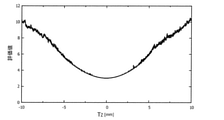
ここで、dpxとf、及び、dpyとfは、スケールの不定性により一意に求める事ができないため、dpyを設計値(一定)とする。また、図3のように配置されたカメラのカメラ画像を用いる場合、2つのカメラのカメラパラメタにおける基線長方向(例えば、X軸方向)の並行移動量TXについても、スケールの不定性により一意に求めることができないため、TXは設計値(一定)とする。これにより、評価値Jは、cu、cv、f、dpx、RX、RY、RZ、TY及びTZによる各カメラで9個のカメラパラメタを変数とする関数となる。 Here, dpx and f, and dpy and f cannot be uniquely obtained due to the indefiniteness of the scale, so dpy is set as a design value (constant). Further, when the camera images of the cameras arranged as shown in FIG. 3 are used, the translation amount TX in the baseline length direction (for example, the X -axis direction) in the camera parameters of the two cameras is also unique due to the indeterminacy of the scale. Since it cannot be obtained in, TX is set to the design value (constant). As a result, the evaluation value J becomes a function in which nine camera parameters are used as variables in each camera by cu, cv , f, dpx , RX, RY , R Z , TY and TZ.
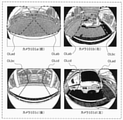
実験に用いた画像が図11に示されている。図11は、駐車場のシーンのカメラ画像の例であり、コンピュータグラフィックス(CG)で生成した。図11は、カメラ101a及び101bのカメラ画像である。本実験では、3次元点群算出部902によって、図11のカメラ画像間の対応点の組を算出する代わりに、予め既知である対応点の組の正解値を用いた。
The image used in the experiment is shown in FIG. FIG. 11 is an example of a camera image of a parking lot scene, which was generated by computer graphics (CG). FIG. 11 is a camera image of the
対応点の組の正解値を入力値として、カメラ101a及び101bの全てのカメラパラメタを正解値である設計値に設定したのち、カメラ101bの1つのカメラパラメタを変えた場合の評価値Jを算出した。
After setting all the camera parameters of the
(実験結果1)
上記の実験条件1による実験結果1を説明する。具体的には、9個のカメラパラメタについて、正解値近傍での評価値が、図12A~図14Bに示すように得られた。各図中の横軸が各カメラパラメタの値を示し、縦軸が評価値Jを示す。変化させるカメラパラメタはそれぞれ、図12Aではcu、図12Bではcv、図12Cではf、図12Dではdpx、図13AではRX、図13BではRY、図13CではRZ、図14AではTY、図14BではTZである。
(Experimental result 1)
The
また、各カメラパラメタの正解値は、cuでは640pixel、cvでは480pixel、fでは1.12mm、dpxでは2.75μm、RXでは0°、RYでは0°、RZでは0°、TYでは0mm、TZでは0mmである。各図中の横軸の中央部がカメラパラメタの正解値である。 The correct answer values for each camera parameter are 640pixel for cu, 480pixel for cv, 1.12 mm for f, 2.75 μm for dpx , 0 ° for RX, 0 ° for RY , 0 ° for RY , and TY. 0 mm for TZ and 0 mm for TZ. The central part of the horizontal axis in each figure is the correct value of the camera parameter.
図12A~図14Bのいずれにおいても、カメラパラメタの正解値の近傍(横軸の中央部)で評価関数は下に凸の線形を描き、且つ、評価値が最小となるカメラパラメタは正解値と一致していることがわかる。このことから、図12A~図14Bで示すカメラパラメタの範囲において、評価値Jが最小となるカメラパラメタを算出できると言える。言い換えると、本方式によるカメラ校正が可能である。 In any of FIGS. 12A to 14B, the evaluation function draws a downwardly convex linear line near the correct value of the camera parameter (center of the horizontal axis), and the camera parameter with the minimum evaluation value is the correct value. You can see that they match. From this, it can be said that the camera parameter having the minimum evaluation value J can be calculated in the range of the camera parameters shown in FIGS. 12A to 14B. In other words, camera calibration by this method is possible.
例えば、図12Aに関して、cuの634~646pixelの範囲において、cuを一定の間隔又はランダムな間隔で増減させながら評価値が算出される。さらに、算出された評価値の中で、評価値が最小となるカメラパラメタcu、又は評価値が十分小さいパラメタcuが、最適値として決定される。このように決定されたカメラパラメタcuは、正解値である又は正解値との誤差が小さいカメラパラメタである。 For example, with respect to FIG. 12A, in the range of 634 to 646pixel of cu, the evaluation value is calculated while increasing or decreasing the cu at regular intervals or random intervals. Further, among the calculated evaluation values, the camera parameter cu that minimizes the evaluation value or the parameter cu that has a sufficiently small evaluation value is determined as the optimum value. The camera parameter cu determined in this way is a camera parameter that is a correct answer value or has a small error from the correct answer value.
以上のことから、式10の評価関数が、正解値の近傍で上述の2つの条件(i)及び(ii)を満たしていることが、実験条件1の実験例により示される。
From the above, it is shown by the experimental example of the
(実験条件2)
実験条件2では、本開示のカメラパラメタセット算出装置111を用いて自己校正処理S111を実施することにより、誤差を小さくするようにカメラパラメタを算出し、算出結果を検証する実験を行った。
(Experimental condition 2)
In the
本実験では、図11のカメラ画像がカメラパラメタセット算出装置111に入力され、カメラ画像間の対応点の組には、実験条件1と同様に、予め既知である正解値が用いられた。また、カメラ101a及び101bの全てのカメラパラメタを正解値である設計値に設定したのち、カメラ101bの9つのカメラパラメタについて所定の範囲内のランダムノイズを加算し、加算後のカメラパラメタを初期カメラパラメタとした。カメラ101bの9つのパラメタのうち1つのパラメタを、所定の範囲内で変化させつつ評価値を算出し、算出された評価値の中で、評価値が最小となるカメラパラメタを最適値に決定する。この処理を9つのカメラパラメタに対して順に繰り返す処理を1回の試行として、さらに複数回の試行を繰り返した。
In this experiment, the camera image of FIG. 11 was input to the camera parameter set
(実験結果2)
上記の実験条件2による実験結果2を説明する。具体的には、実験結果2の例が、図15A及び図15Bに示すように得られた。図15Aでは、横軸が試行回数を示し、縦軸が式10の評価値Jを示す。つまり、図15Aでは、横軸の回数での試行を実施して得られたカメラパラメタを用いて算出した評価値が、縦軸の値で示されている。図15Bでは、横軸が試行回数を示し、縦軸が再投影誤差のRMS値を示す。再投影誤差とは、算出したカメラパラメタが、式1と式3とを満たす度合いを表す。具体的には、カメラ101bのカメラ画像Ibに映った被写体上の3次元座標とその画素座標との組の正解値が既知である場合に、算出したカメラ101bのカメラパラメタを用いて、正解の3次元座標をカメラ画像Ib上に投影した画素座標を算出し、算出した画素座標と正解の画素座標との差を、再投影誤差と呼ぶ。すなわち、再投影誤差が小さいほど、式1及び式3を満たすような、正解との誤差が小さいカメラパラメタであることを表す。図15A及び図15Bのいずれにおいても、試行回数が増えるほど評価値が小さくなる。よって、2つのカメラ画像の投影点における2つの画素値の差が小さくなる。同時に、試行回数が増えるほど再投影誤差も小さくなっている。
(Experimental result 2)
The
以上のことから、本開示のカメラパラメタセット算出装置111による自己校正処理S111によって、再投影誤差が小さい、すなわち、式1及び式3をよく満たし且つ正解値との誤差の小さいカメラパラメタを算出できているといえる。
From the above, the self-calibration process S111 by the camera parameter set
以上のことから、自己校正処理S111によって得られた、上記の式10の評価値Jを最小にするカメラパラメタは、少なくとも評価値Jの評価関数が前述の2つの条件(i)及び(ii)を満たす場合に、正解値、又は誤差の小さいカメラパラメタであると言える。すなわち、カメラパラメタセット算出装置111によるステップS1001~ステップS1007の処理によって、カメラ101a及び101bの2つのカメラ画像と初期カメラパラメタセットとを用いて、カメラ101a及び101bの正確なカメラパラメタを算出して更新できるという効果がある。
From the above, in the camera parameter obtained by the self-calibration process S111 that minimizes the evaluation value J of the
従来の校正技術では、3次元座標と画素座標との対応が既知である複数の基準点を用いるため、校正指標を備える設備等が必要になる。これに対し、本実施の形態に係るカメラパラメタセット算出装置111は、2つのカメラのカメラ画像を用いて対応点の組を抽出し、抽出された対応点の組に対する被写体上の点(測距点)の3次元座標を算出し、さらに3次元座標を用いて各カメラのカメラ画像における対応点の組に含まれる対応点の投影点を算出する。カメラパラメタが正しい場合、2つのカメラ画像の投影点の画素値は一致し、カメラパラメタの誤差が大きいほど2つのカメラ画像の投影点の画素値の差が大きくなる。そこで、カメラパラメタセット算出装置111は、2つのカメラ画像の投影点の画素値の差を最小にするカメラパラメタを算出することで、最適つまり正解のカメラパラメタを算出する。これにより、カメラパラメタセット算出装置111は、3次元座標と画素座標との対応が既知である基準点、つまり校正指標を備える設備等がなくても、カメラの校正を可能にするという効果を奏する。
Since the conventional calibration technique uses a plurality of reference points whose correspondence between the three-dimensional coordinates and the pixel coordinates is known, equipment or the like equipped with a calibration index is required. On the other hand, the camera parameter set
[4-1.自己校正動作の変形例1]
実施の形態に係るカメラパラメタセット算出装置111の自己校正処理では、カメラパラメタの誤差が大きいカメラ、すなわち校正対象のカメラは、ユーザによって特定されており、ユーザによる入力によって特定のカメラの校正動作が開始するものとした。校正対象のカメラの決定は、ユーザにより指定に限定されず、別の方法であってもよい。
[4-1. Modification example of self-calibration operation 1]
In the self-calibration process of the camera parameter set
例えば、3つ以上のカメラがある場合に、全てのカメラを校正するとしてもよい。3つ以上のカメラの全てを校正する場合、例えば、以下の2つの校正が挙げられる。第1の校正では、カメラパラメタセット算出装置111は、複数のカメラによる組から、任意の2つのカメラによる組を複数組抽出し、1組の2つのカメラに対して、実施の形態と同様の自己校正処理によるカメラパラメタセットの算出、つまり校正を行ってもよい。そして、カメラパラメタセット算出装置111は、カメラの複数の組それぞれに対して順に、実施の形態と同様の自己校正処理による校正を行ってもよい。これによって、ユーザが校正対象のカメラを指定することなく、車載カメラシステムの校正ができるという効果がある。例えば、4つのカメラがある場合、6通りのカメラの組が形成される。カメラパラメタセット算出装置111は、6組のカメラそれぞれに対して、順に校正を行ってもよい。これにより、各組のカメラのカメラパラメタセットは、他のカメラの組の影響を低減した校正を受ける。そして、2つのカメラのカメラ画像から得られる結果が、適正か否かを判別することができる。例えば、判別結果に基づき、カメラパラメタセットの変更方法つまり更新方法を検討することができる。さらに、カメラの視野の部分的な領域での校正が可能になる。
For example, if there are three or more cameras, all cameras may be calibrated. When calibrating all three or more cameras, for example, the following two calibrations may be mentioned. In the first calibration, the camera parameter set
また、第2の校正では、カメラパラメタセット算出装置111の取得部901は、3つ以上のカメラのカメラ画像を取得し、3次元点群算出部902は、3つ以上のカメラ画像の重複撮影領域の3次元座標を算出してもよい。さらに、評価値算出部903は、算出した3次元座標を各カメラ画像に投影した投影点の画素値の差を基準にした評価値を算出し、カメラパラメタ決定部904は、評価値を最小にするカメラパラメタを決定してもよい。重複撮影領域それぞれで算出される画素値を、評価値の算出に適用することよって、1つのカメラについて複数の重複撮影領域を用いた校正が可能になる。これにより、校正に利用できる画像の面積が増え、カメラの視野の広い領域にわたる全体的な校正が可能になる。又は、全ての重複撮影領域で算出される画素値を、評価値の算出に適用することよって、複数のカメラ全体の校正が可能になる。
Further, in the second calibration, the
例えば、図16には、図3に示すように配置された4つのカメラ101a~101dが撮影したカメラ画像の例が示されている。各カメラ画像には、複数の重複撮影領域が含まれている。なお、図16は、互いに重複撮影領域を含む4つのカメラ101a~101dの撮影画像の一例である。各カメラ画像には、隣り合う2つのカメラで重複して撮影された被写体の領域である重複撮影領域が含まれる。具体的には、車両の前部のカメラ101aのカメラ画像には、カメラ101aと車両の右側部のカメラ101bとの重複撮影領域OLabと、カメラ101aと車両の左側部のカメラ101dとの重複撮影領域OLadとが含まれている。カメラ101bのカメラ画像には、カメラ101bとカメラ101aとの重複撮影領域OLabと、カメラ101bと車両の後部のカメラ101cとの重複撮影領域OLbcとが含まれている。カメラ101cのカメラ画像には、カメラ101cとカメラ101bとの重複撮影領域OLbcと、カメラ101cとカメラ101dとの重複撮影領域OLcdとが含まれている。カメラ101dのカメラ画像には、カメラ101dとカメラ101cとの重複撮影領域OLcdと、カメラ101dとカメラ101aとの重複撮影領域OLadとが含まれている。
For example, FIG. 16 shows an example of camera images taken by four
第1の校正では、例えば、評価値算出部903は、上記の式10を用いて、2つのカメラの組毎に、重複撮影領域に関して、評価値を算出し、カメラパラメタ決定部904は、カメラの組毎に、評価値を最小にするカメラパラメタを決定する。
In the first calibration, for example, the evaluation
第2の校正では、例えば、評価値算出部903は、上記の式10の代わりに、下記の式13を用いて、全てのカメラの組のカメラ画像の重複撮影領域に関して、重複撮影領域全体に対する評価値を算出する。そして、カメラパラメタ決定部904は、評価値を最小にするカメラパラメタを決定する。式13の評価値Jは、第1項、第2項、第3項及び第4項の和で示される。式13の第1項は、カメラ101a及びカメラ101bのカメラ画像間の重複撮影領域OLabにおけるN個の測距点について、上記の式10を適用したものである。式13の第2項は、カメラ101a及びカメラ101dのカメラ画像間の重複撮影領域OLadにおけるP個の測距点について、上記の式10を適用したものである。式13の第3項は、カメラ101b及びカメラ101cのカメラ画像間の重複撮影領域OLbcにおけるQ個の測距点について、上記の式10を適用したものである。式13の第4項は、カメラ101c及びカメラ101dのカメラ画像間の重複撮影領域OLcdにおけるS個の測距点について、上記の式10を適用したものである。また、式13を用いた場合における図10のステップS1003~S1007の動作を、下記の式14のように表すことができる。式14におけるCar、Cbr、Ccr及びCdrはそれぞれ、カメラ101a、101b、101c及び101dのカメラパラメタセットである。
In the second calibration, for example, the evaluation


実施の形態における自己校正処理では、カメラパラメタセット算出装置111は、カメラ101a及び101bの校正に用いる重複撮影領域として、例えば、図11に示すように、カメラ画像内の偏った一部分を用いた。しかしながら、全てのカメラを校正することによって、全てのカメラの重複撮影領域を校正に用いることになるため、カメラ画像のうちのより広い領域を用いて校正することが可能になる。よって、校正精度を向上できるという効果がある。また、重複撮影領域において重複する画像の数量が3つ以上にならないようにカメラを配置すれば、重複撮影領域の面積が広くなり得る。これにより、さらなる校正精度の向上が可能である。
In the self-calibration process of the embodiment, the camera parameter set
[4-2.自己校正動作の変形例2]
実施の形態に係るカメラパラメタセット算出装置111は、ユーザによる入力を、自己校正処理S111の開始のトリガとしていたが、これに限定されない。カメラパラメタセット算出装置111は、自己校正処理S111の開始を、他のトリガによって自動的に開始してもよい。例えば、カメラパラメタセット算出装置111は、温度センサ、衝撃センサ、タイマ等のセンサからの入力をトリガとして、自動的に自己校正を開始してもよい。
[4-2. Modification example of self-calibration operation 2]
The camera parameter set
例えば、図17を参照すると、センサ部130を備える変形例2に係る車載カメラシステム30の構成を示すブロック図が示されている。車載カメラシステム30は、実施の形態に加えて、温度センサ131、衝撃センサ132及びタイマ133を含むセンサ部130を備える。車載カメラシステム30の画像処理部310のカメラパラメタセット算出装置311は、実施の形態に加えて、センサ部130から検知情報を取得し自己校正処理の開始指令を出力するセンサ情報取得部906を備える。
For example, referring to FIG. 17, a block diagram showing a configuration of an in-
本変形例に係るカメラパラメタセット算出装置311は、車載カメラシステム30の電源投入直後に、1回の自己校正処理を、実施してもよい。なお、上記の電源投入後の実施の代わりに又は加えて、カメラパラメタセット算出装置311は、自己校正処理を、センサ部130のタイマ133からの入力に基づいて実施してもよく、センサ部130の衝撃センサ132からの入力に基づいて実施してもよく、センサ部130の温度センサ131の入力に基づいて実施してもよい。タイマ133からの入力に基づいた実施は、タイマ133によって検知される一定の時間ごとの実施であってもよい。衝撃センサ132からの入力に基づく実施は、車載カメラシステム30が搭載された自動車に事故などによって加わる強い衝撃を衝撃センサ132が検知する場合に行われてもよい。なお、衝撃センサ132は、加速度センサで構成されてもよい。温度センサ131の入力に基づく実施は、車載カメラシステム30の周囲の温度が所定の温度になることを温度センサ131が検知する場合に行われてもよい。
The camera parameter set
[4-3.自己校正動作の変形例3]
実施の形態に係るカメラパラメタセット算出装置111は、自己校正処理S111において、ステップS1003では、カメラ画像Ia及びIb間でN個の対応点の組を抽出し、さらに抽出されたN個の対応点の組のそれぞれに対する被写体上の点(測距点)の3次元座標をステレオ測距技術により算出し、ステップS1004では、3次元座標を用いて評価値Jを算出した。しかしながら、評価値Jの算出に測距点を全て用いる必要はない。
[4-3. Modification example of self-calibration operation 3]
In the self-calibration process S111, the camera parameter set
本変形例では、カメラパラメタセット算出装置111は、ステレオ測距によって算出したN個の測距点の3次元座標のうちから、画像の輝度勾配が無い又は十分小さい測距点の3次元座標を取り除く。これにより、カメラパラメタセット算出装置111は、評価値Jの算出に用いる測距点を少なくし、評価値Jの算出における計算量を低減する。
In this modification, the camera parameter set
本変形例に係るカメラパラメタセット算出装置111の自己校正処理は、ステップS1004の動作を除き、実施の形態と同様である。このため、本変形例に係るステップS1004の動作を説明し、その他の説明を省略する。
The self-calibration process of the camera parameter set
ステップS1004において、カメラパラメタセット算出装置111の評価値算出部903は、測距点の3次元座標と、カメラ101a及び101bのカメラパラメタセットCar及びCbrとを用いて、上記の式8及び式9により、測距点をカメラ101aのカメラ画像Iaに投影した第1投影点の画素座標及び同一の測距点をカメラ101bのカメラ画像Ibに投影した第2投影点の画素座標を算出する。
In step S1004, the evaluation
そして、Ka個の測距点が存在する場合、評価値算出部903は、Ka個の測距点のうちから、測距点をカメラ画像Iaに投影した第1投影点の画素座標(uar,var)における画素値の輝度勾配が0又は十分小さい測距点を除去する。除去される測距点が、Kb個(Kb>又は=0)存在する場合、評価値算出部903は、(Ka-Kb)個の測距点の3次元座標を選択する。
Then, when there are Ka distance measuring points, the evaluation
測距点の3次元座標(xar,yar,zar)に対応する画素座標(uar,var)の周りの画素値の輝度勾配が0の場合、カメラパラメタを微小変化させることで、この測距点に対応する画素座標(uar,var)が微小変化しても、その画素座標の画素値Ia(uar,var)は変化しない。言い換えると、評価値Jが変化しない。そのため、この様な測距点を除去したとしても評価値Jには影響が無く、且つ、測距点の数が減るため、ステップS1004の計算量を低減できるという効果がある。 When the brightness gradient of the pixel values around the pixel coordinates (ua, var) corresponding to the three-dimensional coordinates (xar, jar, zar) of the range-finding point is 0, the range-finding point is changed slightly by slightly changing the camera parameter. Even if the pixel coordinates (uer, var) corresponding to the above are slightly changed, the pixel value Ia (uer, var) of the pixel coordinates does not change. In other words, the evaluation value J does not change. Therefore, even if such a range-finding point is removed, the evaluation value J is not affected and the number of range-finding points is reduced, so that there is an effect that the calculation amount in step S1004 can be reduced.
なお、ステップS1004における評価値Jの算出に用いる測距点の削減には、他の手法が用いられてもよい。例えば、測距点のうちから、2つのカメラ101a及び101bの一方のカメラに映っていない測距点が除外されてもよい。この場合、測距点の3次元座標に対応する投影点のカメラ画像Ia及びIbでの画素座標を算出し、2つの画素座標のうちいずれか一方がカメラ画像の不可視領域に位置する場合に、当該測距点を評価値Jの算出から除外してもよい。
In addition, another method may be used for reducing the range-finding points used for calculating the evaluation value J in step S1004. For example, the range-finding points that are not reflected in one of the two
上記の式10は、同一の測距点が2つのカメラ画像Ia及びIbに写っている場合、カメラ画像Ia及びIbでの測距点の投影点の画素値の差が0になることを意味している。カメラ画像Ia及びIbでの測距点の投影点のいずれかが、カメラ101a及び101bの撮影範囲外にある場合、撮影範囲内にあっても他の物体に遮蔽されてカメラに映らない、つまり遮蔽領域にある場合では、画素値の差は、0にならず、評価値の誤差になる。そのため、複数の測距点のうち、その投影点が少なくとも一方のカメラに写らない、つまり、当該カメラの不可視領域に位置する測距点を評価値の算出から除外することで、評価値の誤差を小さくできるという効果が期待できる。測距点の投影点がカメラの不可視領域にあるか否かは、前述したようなカメラの撮影範囲外となる3次元空間の範囲を規定する遮蔽情報に基づいて判定してもよい。
なお、カメラパラメタセット算出装置111の自己校正処理S111のステップS1005では、評価値Jが第一閾値よりも小さいこと、及び、処理の繰り返し回数rが第二閾値よりも大きいこと等の終了条件に基づき、反復計算を終了するとしたが、反復計算の終了条件をこれに限定するものではない。例えば、他の終了条件が加わってもよい。例えば、カメラパラメタセットを変化させても評価値Jが変化しないことを、終了条件としてもよい。
In step S1005 of the self-calibration process S111 of the camera parameter set
なお、カメラパラメタセット算出装置111の自己校正処理S111は、評価値Jの評価関数が前述した2つの条件を満たす場合に、評価値Jが小さい、つまり正解値とカメラパラメタとの差が小さい、言い換えると、誤差の小さいカメラパラメタを算出して更新することができる。しかしながら、評価関数が前述した2つの条件を満たさない場合、必ずしも誤差の小さいカメラパラメタを算出できるとは限らない。例えば、カメラの撮影範囲が極端に暗く、全ての画素値が0になる場合、及び、被写体が均一色でテクスチャが全くない場合、上記の式10の評価値Jは、カメラパラメタを変えてもその値は変わらず、一定値(例えば、0)となる。このようなカメラ画像をカメラパラメタセット算出装置111が取得した場合、自己校正処理S111では、ステップS1003~S1006の反復回数rが第二閾値以上になるまで反復処理が終了せず、評価値は一定のままで更新されない。この際、カメラパラメタを更新しないにも関わらず、処理における計算負荷がかかる。これに対し、カメラパラメタを変化させても評価値が変化しない場合に、反復処理を終了するとすることで、計算負荷を低減できるという効果がある。
In the self-calibration process S111 of the camera parameter set
[5.評価関数のバリエーション]
実施の形態及び変形例に係る自己校正処理において、カメラパラメタセット算出装置の自己校正処理で用いる評価値Jに、上記の式10に示すように、複数の測距点それぞれに対応する画素値の差の絶対値の和に基づく評価関数が適用された。しかしながら、評価関数は、上記に限定されるものではなく、測距点に対応する2つのカメラ画像の画素値の差に基づく関数であれば、他の関数であってもよい。例えば、評価関数は、複数の測距点それぞれに対応する2つのカメラ画像の2つの画素値の差の2乗の総和を用いる評価関数でもよい。具体的には、測距点をカメラ画像Iaへ投影した第1投影点での画素値と同一の測距点をカメラ画像Ibへ投影した第2投影点での画素値との差の2乗を各測距点について求めて、求めた値を加算する評価関数の例を、下記の式15に示す。
[5. Variation of evaluation function]
In the self-calibration process according to the embodiment and the modification, the evaluation value J used in the self-calibration process of the camera parameter set calculation device is the pixel value corresponding to each of the plurality of AF points as shown in the

上記の式10に示すような画素値の差の絶対値和で定義される評価値に基づいて算出されたカメラパラメタは、画素値の差がラプラス分布の場合に、真値に近い、つまり、真値に対する誤差が小さいという効果が期待できる。
The camera parameter calculated based on the evaluation value defined by the absolute value sum of the pixel value differences as shown in the
これに対し、上記の式15に示すような画素値の差の2乗和で定義される評価値に基づいて算出されたカメラパラメタは、画素値の誤差がガウス分布の場合に、真値に近い、つまり、真値に対する誤差が小さいという効果が期待できる。
On the other hand, the camera parameter calculated based on the evaluation value defined by the sum of squares of the difference in pixel values as shown in the
[その他]
以上、本開示の1つ以上の態様に係るカメラパラメタセット算出装置等について、実施の形態等に基づいて説明したが、本開示は、実施の形態等に限定されるものではない。本開示の趣旨を逸脱しない限り、当業者が思いつく各種変形を本実施の形態等に施したものや、異なる実施の形態における構成要素を組み合わせて構築される形態も、本開示の1つ以上の態様の範囲内に含まれてもよい。
[others]
Although the camera parameter set calculation device and the like according to one or more aspects of the present disclosure have been described above based on the embodiments and the like, the present disclosure is not limited to the embodiments and the like. As long as it does not deviate from the gist of the present disclosure, one or more of the present disclosure may be a form in which various modifications conceived by a person skilled in the art are applied to the present embodiment or the like, or a form constructed by combining components in different embodiments. It may be included within the scope of the embodiment.
実施の形態及び変形例では、撮像部100は4つのカメラ101a~101dで構成されるものとしたが、カメラの数量を4つに限定するものではない。本開示の自己校正のためには、撮像部100は、少なくとも2つのカメラを備えればよく、カメラは2つ以上であればいくらでもよい。また、カメラ同士は、一体化されていてもよく、別々に配置されていてもよい。
In the embodiment and the modified example, the
実施の形態及び変形例では、車載カメラシステムの撮像部、画像処理部及びディスプレイは、いずれも自動車に搭載されており、画像処理部を構成するカメラパラメタセット算出装置も自動車に搭載されているものとしたが、これに限定されない。例えば、撮像部、画像処理部及びディスプレイは、自動車以外のいかなる移動体に搭載されてもよい。移動体は、自動車以外の車両、船舶、飛行体又はロボット等であってもよい。自動車以外の車両は、トラック、バス、二輪車、搬送車、鉄道、建設機械、荷役機械等であってもよい。飛行体は、航空機、ドローン等であってもよい。ロボットは、利用者が遠隔操作する構成であってもよい。 In the embodiment and the modified example, the image pickup unit, the image processing unit, and the display of the in-vehicle camera system are all mounted on the automobile, and the camera parameter set calculation device constituting the image processing unit is also mounted on the automobile. However, it is not limited to this. For example, the image pickup unit, the image processing unit, and the display may be mounted on any moving body other than an automobile. The moving body may be a vehicle other than an automobile, a ship, a flying body, a robot, or the like. Vehicles other than automobiles may be trucks, buses, two-wheeled vehicles, transport vehicles, railways, construction machinery, cargo handling machinery, and the like. The flying object may be an aircraft, a drone, or the like. The robot may be configured to be remotely controlled by the user.
また、カメラパラメタセット算出装置は、自動車とネットワークで接続された別の場所に設置されているコンピュータで構成してもよい。カメラパラメタセット算出装置におけるカメラパラメタの自己校正処理は、計算負荷が大きいことから、自動車に搭載された計算能力に制約のあるコンピュータ上で実施するよりも、サーバーなどの計算能力の高いコンピュータで実施することで、計算時間がより短く、精度がより高いパラメタの算出ができる、という効果がある。 Further, the camera parameter set calculation device may be configured by a computer installed in another place connected to the automobile by a network. Since the calculation load of the camera parameter self-calibration process in the camera parameter set calculation device is large, it is performed on a computer with high calculation power such as a server rather than on a computer with limited calculation power installed in a car. This has the effect that the calculation time is shorter and the parameters with higher accuracy can be calculated.
また、上述したように、本開示の技術は、システム、装置、方法、集積回路、コンピュータプログラム又はコンピュータ読取可能な記録ディスク等の記録媒体で実現されてもよく、システム、装置、方法、集積回路、コンピュータプログラム及び記録媒体の任意な組み合わせで実現されてもよい。コンピュータ読み取り可能な記録媒体は、例えばCD-ROM等の不揮発性の記録媒体を含む。 Further, as described above, the technique of the present disclosure may be realized by a recording medium such as a system, an apparatus, a method, an integrated circuit, a computer program or a computer-readable recording disk, and the system, an apparatus, a method, an integrated circuit may be realized. , Computer programs and any combination of recording media. Computer-readable recording media include non-volatile recording media such as CD-ROMs.
例えば、上記実施の形態及び変形例に係る車載カメラシステムに含まれる各構成要素は典型的には集積回路であるLSI(Large Scale Integration:大規模集積回路)として実現される。これらは個別に1チップ化されてもよいし、一部又は全てを含むように1チップ化されてもよい。 For example, each component included in the vehicle-mounted camera system according to the above-described embodiment and modification is typically realized as an LSI (Large Scale Integration) which is an integrated circuit. These may be individually integrated into one chip, or may be integrated into one chip so as to include a part or all of them.
また、集積回路化はLSIに限るものではなく、専用回路又は汎用プロセッサで実現してもよい。LSI製造後にプログラムすることが可能なFPGA(Field Programmable Gate Array)、又はLSI内部の回路セルの接続や設定を再構成可能なリコンフィギュラブル・プロセッサを利用してもよい。 Further, the integrated circuit is not limited to the LSI, and may be realized by a dedicated circuit or a general-purpose processor. An FPGA (Field Programmable Gate Array) that can be programmed after the LSI is manufactured, or a reconfigurable processor that can reconfigure the connection and settings of circuit cells inside the LSI may be used.
なお、上記実施の形態及び変形例において、各構成要素は、専用のハードウェアで構成されるか、各構成要素に適したソフトウェアプログラムを実行することによって実現されてもよい。各構成要素は、CPU又はプロセッサなどのプログラム実行部が、ハードディスク又は半導体メモリなどの記録媒体に記録されたソフトウェアプログラムを読み出して実行することによって実現されてもよい。 In the above-described embodiment and modification, each component may be configured by dedicated hardware or may be realized by executing a software program suitable for each component. Each component may be realized by a program execution unit such as a CPU or a processor reading and executing a software program recorded on a recording medium such as a hard disk or a semiconductor memory.
また、上記構成要素の一部又は全部は、脱着可能なIC(Integrated Circuit)カード又は単体のモジュールから構成されてもよい。ICカード又はモジュールは、マイクロプロセッサ、ROM、RAM等から構成されるコンピュータシステムである。ICカード又はモジュールは、上記のLSI又はシステムLSIを含むとしてもよい。マイクロプロセッサが、コンピュータプログラムにしたがって動作することにより、ICカード又はモジュールは、その機能を達成する。これらICカード及びモジュールは、耐タンパ性を有するとしてもよい。 Further, a part or all of the above components may be composed of a removable IC (Integrated Circuit) card or a single module. An IC card or module is a computer system composed of a microprocessor, ROM, RAM, and the like. The IC card or module may include the above LSI or system LSI. When the microprocessor operates according to a computer program, the IC card or module achieves its function. These IC cards and modules may have tamper resistance.
本開示のカメラパラメタセット算出方法は、MPU(Micro Processing Unit)、CPU、プロセッサ、LSIなどの回路、ICカード又は単体のモジュール等によって、実現されてもよい。 The camera parameter set calculation method of the present disclosure may be realized by a circuit such as an MPU (Micro Processing Unit), a CPU, a processor, an LSI, an IC card, a single module, or the like.
さらに、本開示の技術は、ソフトウェアプログラム又はソフトウェアプログラムからなるデジタル信号によって実現されてもよく、プログラムが記録された非一時的なコンピュータ読み取り可能な記録媒体であってもよい。また、上記プログラムは、インターネット等の伝送媒体を介して流通させることができるのは言うまでもない。 Further, the technique of the present disclosure may be realized by a software program or a digital signal consisting of the software program, or may be a non-temporary computer-readable recording medium in which the program is recorded. Needless to say, the above program can be distributed via a transmission medium such as the Internet.
また、上記で用いた序数、数量等の数字は、全て本開示の技術を具体的に説明するために例示するものであり、本開示は例示された数字に制限されない。また、構成要素間の接続関係は、本開示の技術を具体的に説明するために例示するものであり、本開示の機能を実現する接続関係はこれに限定されない。 In addition, the numbers such as the ordinal number and the quantity used above are all exemplified for the purpose of concretely explaining the technique of the present disclosure, and the present disclosure is not limited to the exemplified numbers. Further, the connection relationship between the components is exemplified for concretely explaining the technique of the present disclosure, and the connection relationship for realizing the function of the present disclosure is not limited to this.
また、ブロック図における機能ブロックの分割は一例であり、複数の機能ブロックを1つの機能ブロックとして実現したり、1つの機能ブロックを複数に分割したり、一部の機能を他の機能ブロックに移してもよい。また、類似する機能を有する複数の機能ブロックの機能を単一のハードウェア又はソフトウェアが並列又は時分割に処理してもよい。 Further, the division of the functional block in the block diagram is an example, and a plurality of functional blocks can be realized as one functional block, one functional block can be divided into a plurality, and some functions can be transferred to other functional blocks. You may. Further, the functions of a plurality of functional blocks having similar functions may be processed by a single hardware or software in parallel or in a time division manner.
本開示に係るカメラパラメタ算出装置等は、少なくとも2つのカメラのカメラパラメタの算出に有用である。 The camera parameter calculation device and the like according to the present disclosure are useful for calculating the camera parameters of at least two cameras.
10,30 車載カメラシステム
100 撮像部
101,101a,101b カメラ
110,310 画像処理部
111,311 カメラパラメタセット算出装置
112 カメラパラメタ記憶部
113 画像生成部
120 ディスプレイ
300 コンピュータ
301 CPU
302 ROM
303 RAM
304 HDD
305 ビデオ入力I/F
306 ビデオカード
901 取得部
902 3次元点群算出部
903 評価値算出部
904 カメラパラメタ決定部
905 カメラパラメタ出力部
906 センサ情報取得部
10, 30 In-
302 ROM
303 RAM
304 HDD
305 Video Input I / F
306
Claims (21)
前記少なくとも1つの制御回路は、
(a1)前記複数のカメラの第1カメラで撮影された第1画像と、前記複数のカメラの第2カメラで撮影された第2画像とを取得し、
(a2)前記第1カメラの1つ以上のカメラパラメタを含む第1カメラパラメタセットと、前記第2カメラの1つ以上のカメラパラメタを含む第2カメラパラメタセットとを取得し、
(a3)前記第1画像、前記第2画像、前記第1カメラパラメタセット及び前記第2カメラパラメタセットに基づいて、前記第1画像及び前記第2画像における被写体が部分的に重複して映し出される重複領域上の3次元座標を複数算出し、
(a4)前記第1カメラパラメタセットに基づいて前記複数の3次元座標を前記第1画像に投影した複数の第1画素座標を決定し、前記第2カメラパラメタセットに基づいて前記複数の3次元座標を前記第2画像に投影した複数の第2画素座標を決定し、
(a5)前記第1画像における前記複数の第1画素座標での複数の画素値と前記第2画像における前記複数の第2画素座標での複数の画素値とに基づいて評価値を算出し、
(a6)前記評価値に基づいて、前記第1カメラパラメタセット及び前記第2カメラパラメタセットを更新し、
(a7)更新された前記第1カメラパラメタセット及び前記第2カメラパラメタセットを出力する
カメラパラメタセット算出装置。 It is provided with at least one control circuit for calculating a camera parameter set using images taken by a plurality of cameras and the camera parameter sets of the plurality of cameras.
The at least one control circuit
(A1) The first image taken by the first camera of the plurality of cameras and the second image taken by the second camera of the plurality of cameras are acquired.
(A2) The first camera parameter set including one or more camera parameters of the first camera and the second camera parameter set including one or more camera parameters of the second camera are acquired.
(A3) The subjects in the first image and the second image are partially overlapped and projected based on the first image, the second image, the first camera parameter set, and the second camera parameter set. Calculate multiple 3D coordinates on the overlapping area and calculate
(A4) A plurality of first pixel coordinates obtained by projecting the plurality of three-dimensional coordinates onto the first image are determined based on the first camera parameter set, and the plurality of three dimensions are determined based on the second camera parameter set. A plurality of second pixel coordinates obtained by projecting the coordinates onto the second image are determined.
(A5) An evaluation value is calculated based on a plurality of pixel values at the plurality of first pixel coordinates in the first image and a plurality of pixel values at the plurality of second pixel coordinates in the second image.
(A6) The first camera parameter set and the second camera parameter set are updated based on the evaluation value.
(A7) A camera parameter set calculation device that outputs the updated first camera parameter set and the second camera parameter set.
(i)車両の前部に配置されたカメラで前記車両の前方を撮影した画像、及び前記車両の左部に配置されたカメラで前記車両の左方を撮影した画像の組み合わせ、
(ii)車両の前部に配置されたカメラで前記車両の前方を撮影した画像、及び前記車両の右部に配置されたカメラで前記車両の右方を撮影した画像の組み合わせ、
(iii)車両の後部に配置されたカメラで前記車両の後方を撮影した画像、及び前記車両の左部に配置されたカメラで前記車両の左方を撮影した画像の組み合わせ、
(iv)車両の後部に配置されたカメラで前記車両の後方を撮影した画像、及び前記車両の右部に配置されたカメラで前記車両の右方を撮影した画像の組み合わせ、
のうちのいずれかの組み合わせである
請求項1に記載のカメラパラメタセット算出装置。 The first image and the second image are
(I) A combination of an image of the front of the vehicle taken by a camera placed at the front of the vehicle and an image of the left side of the vehicle taken by a camera placed at the left side of the vehicle.
(Ii) A combination of an image of the front of the vehicle taken by a camera arranged at the front of the vehicle and an image of the right side of the vehicle taken by a camera placed at the right side of the vehicle.
(Iii) A combination of an image of the rear of the vehicle taken by a camera placed at the rear of the vehicle and an image of the left side of the vehicle taken with a camera placed at the left side of the vehicle.
(Iv) A combination of an image of the rear of the vehicle taken by a camera placed at the rear of the vehicle and an image of the right side of the vehicle taken with a camera placed at the right side of the vehicle.
The camera parameter set calculation device according to claim 1, which is a combination of any of the above.
処理(a5)では、前記第1画素座標における前記第1画像の画素値と前記第2画素座標における前記第2画像の画素値との差異に基づいて前記評価値を算出する
請求項1または2に記載のカメラパラメタセット算出装置。 The at least one control circuit
In the process (a5), claim 1 or 2 calculates the evaluation value based on the difference between the pixel value of the first image in the first pixel coordinates and the pixel value of the second image in the second pixel coordinates. The camera parameter set calculation device described in.
前記複数のカメラの第3カメラで撮影された第3画像と、前記第3カメラの第3カメラパラメタセットとをさらに取得し、
前記第1画像、前記第2画像及び前記第3画像から、2つの画像により構成される複数の組を決定し、
前記複数の組それぞれに含まれる2つの画像に対して、処理(a3)~処理(a5)を順次行う
請求項1~3のいずれか一項に記載のカメラパラメタセット算出装置。 The at least one control circuit
The third image taken by the third camera of the plurality of cameras and the third camera parameter set of the third camera are further acquired.
From the first image, the second image, and the third image, a plurality of sets composed of the two images are determined.
The camera parameter set calculation device according to any one of claims 1 to 3, wherein processing (a3) to processing (a5) are sequentially performed on two images included in each of the plurality of sets.
前記複数のカメラの第3カメラで撮影された第3画像と、前記第3カメラの第3カメラパラメタセットとをさらに取得し、
前記第1画像、前記第2画像及び前記第3画像から、2つの画像により構成される複数の組を決定し、
前記複数の組それぞれに含まれる2つの画像に対して、処理(a3)~処理(a5)を行って得られる画素値を用いて、前記評価値を算出する
請求項1~3のいずれか一項に記載のカメラパラメタセット算出装置。 The at least one control circuit
The third image taken by the third camera of the plurality of cameras and the third camera parameter set of the third camera are further acquired.
From the first image, the second image, and the third image, a plurality of sets composed of the two images are determined.
Any one of claims 1 to 3 for calculating the evaluation value using the pixel values obtained by performing the processing (a3) to the processing (a5) on the two images included in each of the plurality of sets. The camera parameter set calculator described in section.
前記第2画像及び前記第3画像は、被写体の一部が重複して映る第2重複領域を含み、
前記第1重複領域と前記第2重複領域とは、重複しない
請求項4または5に記載のカメラパラメタセット算出装置。 The first image and the second image include a first overlapping region in which a part of the subject is overlapped.
The second image and the third image include a second overlapping region in which a part of the subject is overlapped.
The camera parameter set calculation device according to claim 4 or 5, wherein the first overlapping area and the second overlapping area do not overlap.
請求項1~6のいずれか一項に記載のカメラパラメタセット算出装置。 The first image and the second image are images taken by the first camera and the second camera arranged so that the directions of the optical axes at the center of the optical axis intersect each other, respectively. The camera parameter set calculation device according to any one of claims 1 to 6.
(a2)前記第1カメラの1つ以上のカメラパラメタを含む第1カメラパラメタセットと、前記第2カメラの1つ以上のカメラパラメタを含む第2カメラパラメタセットとを取得し、
(a3)前記第1画像、前記第2画像、前記第1カメラパラメタセット及び前記第2カメラパラメタセットに基づいて、前記第1画像及び前記第2画像における被写体が部分的に重複して映し出される重複領域上の3次元座標を複数算出し、
(a4)前記第1カメラパラメタセットに基づいて前記複数の3次元座標を前記第1画像に投影した複数の第1画素座標を決定し、前記第2カメラパラメタセットに基づいて前記複数の3次元座標を前記第2画像に投影した複数の第2画素座標を決定し、
(a5)前記第1画像における前記複数の第1画素座標での複数の画素値と前記第2画像における前記複数の第2画素座標での複数の画素値とに基づいて評価値を算出し、
(a6)前記評価値に基づいて、前記第1カメラパラメタセット及び前記第2カメラパラメタセットを更新し、
(a7)更新された前記第1カメラパラメタセット及び前記第2カメラパラメタセットを出力し、
処理(a1)~処理(a7)の少なくとも1つがプロセッサによって実行される
カメラパラメタセット算出方法。 (A1) The first image taken by the first camera of the plurality of cameras and the second image taken by the second camera of the plurality of cameras are acquired.
(A2) The first camera parameter set including one or more camera parameters of the first camera and the second camera parameter set including one or more camera parameters of the second camera are acquired.
(A3) The subjects in the first image and the second image are partially overlapped and projected based on the first image, the second image, the first camera parameter set, and the second camera parameter set. Calculate multiple 3D coordinates on the overlapping area and calculate
(A4) A plurality of first pixel coordinates obtained by projecting the plurality of three-dimensional coordinates onto the first image are determined based on the first camera parameter set, and the plurality of three dimensions are determined based on the second camera parameter set. A plurality of second pixel coordinates obtained by projecting the coordinates onto the second image are determined.
(A5) An evaluation value is calculated based on a plurality of pixel values at the plurality of first pixel coordinates in the first image and a plurality of pixel values at the plurality of second pixel coordinates in the second image.
(A6) The first camera parameter set and the second camera parameter set are updated based on the evaluation value.
(A7) The updated first camera parameter set and the second camera parameter set are output.
A camera parameter set calculation method in which at least one of processes (a1) to (a7) is executed by a processor.
(i)車両の前部に配置されたカメラで前記車両の前方を撮影した画像、及び前記車両の左部に配置されたカメラで前記車両の左方を撮影した画像の組み合わせ、
(ii)車両の前部に配置されたカメラで前記車両の前方を撮影した画像、及び前記車両の右部に配置されたカメラで前記車両の右方を撮影した画像の組み合わせ、
(iii)車両の後部に配置されたカメラで前記車両の後方を撮影した画像、及び前記車両の左部に配置されたカメラで前記車両の左方を撮影した画像の組み合わせ、
(iv)車両の後部に配置されたカメラで前記車両の後方を撮影した画像、及び前記車両の右部に配置されたカメラで前記車両の右方を撮影した画像の組み合わせ、
のうちのいずれかの組み合わせである
請求項8に記載のカメラパラメタセット算出方法。 The first image and the second image are
(I) A combination of an image of the front of the vehicle taken by a camera placed at the front of the vehicle and an image of the left side of the vehicle taken by a camera placed at the left side of the vehicle.
(Ii) A combination of an image of the front of the vehicle taken by a camera arranged at the front of the vehicle and an image of the right side of the vehicle taken by a camera placed at the right side of the vehicle.
(Iii) A combination of an image of the rear of the vehicle taken by a camera placed at the rear of the vehicle and an image of the left side of the vehicle taken with a camera placed at the left side of the vehicle.
(Iv) A combination of an image of the rear of the vehicle taken by a camera placed at the rear of the vehicle and an image of the right side of the vehicle taken with a camera placed at the right side of the vehicle.
The camera parameter set calculation method according to claim 8, which is a combination of any of the above.
請求項8または9に記載のカメラパラメタセット算出方法。 In the process (a5), claim 8 or 9 calculates the evaluation value based on the difference between the pixel value of the first image in the first pixel coordinates and the pixel value of the second image in the second pixel coordinates. The camera parameter set calculation method described in.
前記第1画像、前記第2画像及び前記第3画像から、2つの画像により構成される複数の組を決定し、
前記複数の組それぞれに含まれる2つの画像に対して、処理(a3)~処理(a5)を順次行う
請求項8~10のいずれか一項に記載のカメラパラメタセット算出方法。 The third image taken by the third camera of the plurality of cameras and the third camera parameter set of the third camera are further acquired.
From the first image, the second image, and the third image, a plurality of sets composed of the two images are determined.
The camera parameter set calculation method according to any one of claims 8 to 10, wherein processing (a3) to processing (a5) are sequentially performed on two images included in each of the plurality of sets.
前記第1画像、前記第2画像及び前記第3画像から、2つの画像により構成される複数の組を決定し、
前記複数の組それぞれに含まれる2つの画像に対して、処理(a3)~処理(a5)を行って得られる画素値を用いて、前記評価値を算出する
請求項8~10のいずれか一項に記載のカメラパラメタセット算出方法。 The third image taken by the third camera of the plurality of cameras and the third camera parameter set of the third camera are further acquired.
From the first image, the second image, and the third image, a plurality of sets composed of the two images are determined.
Any one of claims 8 to 10 for calculating the evaluation value using the pixel values obtained by performing the processing (a3) to the processing (a5) on the two images included in each of the plurality of sets. The camera parameter set calculation method described in the section.
前記第2画像及び前記第3画像は、被写体の一部が重複して映る第2重複領域を含み、
前記第1重複領域と前記第2重複領域とは、重複しない
請求項11または12に記載のカメラパラメタセット算出方法。 The first image and the second image include a first overlapping region in which a part of the subject is overlapped.
The second image and the third image include a second overlapping region in which a part of the subject is overlapped.
The camera parameter set calculation method according to claim 11 or 12, wherein the first overlapping area and the second overlapping area do not overlap.
請求項8~13のいずれか一項に記載のカメラパラメタセット算出方法。 The first image and the second image are images taken by the first camera and the second camera arranged so that the directions of the optical axes at the center of the optical axis intersect each other, respectively. The camera parameter set calculation method according to any one of claims 8 to 13.
(a1)複数のカメラの第1カメラで撮影された第1画像と、前記複数のカメラの第2カメラで撮影された第2画像とを取得し、
(a2)前記第1カメラの1つ以上のカメラパラメタを含む第1カメラパラメタセットと、前記第2カメラの1つ以上のカメラパラメタを含む第2カメラパラメタセットとを取得し、
(a3)前記第1画像、前記第2画像、前記第1カメラパラメタセット及び前記第2カメラパラメタセットに基づいて、前記第1画像及び前記第2画像における被写体が部分的に重複して映し出される重複領域上の3次元座標を複数算出し、
(a4)前記第1カメラパラメタセットに基づいて前記複数の3次元座標を前記第1画像に投影した複数の第1画素座標を決定し、前記第2カメラパラメタセットに基づいて前記複数の3次元座標を前記第2画像に投影した複数の第2画素座標を決定し、
(a5)前記第1画像における前記複数の第1画素座標での複数の画素値と前記第2画像における前記複数の第2画素座標での複数の画素値とに基づいて評価値を算出し、
(a6)前記評価値に基づいて、前記第1カメラパラメタセット及び前記第2カメラパラメタセットを更新し、
(a7)更新された前記第1カメラパラメタセット及び前記第2カメラパラメタセットを出力する
ことを前記コンピュータに実行させるプログラム。 A program that lets a computer run
(A1) The first image taken by the first camera of the plurality of cameras and the second image taken by the second camera of the plurality of cameras are acquired.
(A2) The first camera parameter set including one or more camera parameters of the first camera and the second camera parameter set including one or more camera parameters of the second camera are acquired.
(A3) The subjects in the first image and the second image are partially overlapped and projected based on the first image, the second image, the first camera parameter set, and the second camera parameter set. Calculate multiple 3D coordinates on the overlapping area and calculate
(A4) A plurality of first pixel coordinates obtained by projecting the plurality of three-dimensional coordinates onto the first image are determined based on the first camera parameter set, and the plurality of three dimensions are determined based on the second camera parameter set. A plurality of second pixel coordinates obtained by projecting the coordinates onto the second image are determined.
(A5) An evaluation value is calculated based on a plurality of pixel values at the plurality of first pixel coordinates in the first image and a plurality of pixel values at the plurality of second pixel coordinates in the second image.
(A6) The first camera parameter set and the second camera parameter set are updated based on the evaluation value.
(A7) A program for causing the computer to output the updated first camera parameter set and the second camera parameter set.
(i)車両の前部に配置されたカメラで前記車両の前方を撮影した画像、及び前記車両の左部に配置されたカメラで前記車両の左方を撮影した画像の組み合わせ、
(ii)車両の前部に配置されたカメラで前記車両の前方を撮影した画像、及び前記車両の右部に配置されたカメラで前記車両の右方を撮影した画像の組み合わせ、
(iii)車両の後部に配置されたカメラで前記車両の後方を撮影した画像、及び前記車両の左部に配置されたカメラで前記車両の左方を撮影した画像の組み合わせ、
(iv)車両の後部に配置されたカメラで前記車両の後方を撮影した画像、及び前記車両の右部に配置されたカメラで前記車両の右方を撮影した画像の組み合わせ、
のうちのいずれかの組み合わせである
請求項15に記載のプログラム。 The first image and the second image are
(I) A combination of an image of the front of the vehicle taken by a camera placed at the front of the vehicle and an image of the left side of the vehicle taken by a camera placed at the left side of the vehicle.
(Ii) A combination of an image of the front of the vehicle taken by a camera arranged at the front of the vehicle and an image of the right side of the vehicle taken by a camera placed at the right side of the vehicle.
(Iii) A combination of an image of the rear of the vehicle taken by a camera placed at the rear of the vehicle and an image of the left side of the vehicle taken with a camera placed at the left side of the vehicle.
(Iv) A combination of an image of the rear of the vehicle taken by a camera placed at the rear of the vehicle and an image of the right side of the vehicle taken with a camera placed at the right side of the vehicle.
The program according to claim 15, which is a combination of any of the above.
請求項15または16に記載のプログラム。 In the process (a5), claim 15 or 16 calculates the evaluation value based on the difference between the pixel value of the first image in the first pixel coordinates and the pixel value of the second image in the second pixel coordinates. The program described in.
前記第1画像、前記第2画像及び前記第3画像から、2つの画像により構成される複数の組を決定し、
前記複数の組それぞれに含まれる2つの画像に対して、処理(a3)~処理(a5)を順次行う
請求項15~17のいずれか一項に記載のプログラム。 The third image taken by the third camera of the plurality of cameras and the third camera parameter set of the third camera are further acquired.
From the first image, the second image, and the third image, a plurality of sets composed of the two images are determined.
The program according to any one of claims 15 to 17, wherein processing (a3) to processing (a5) are sequentially performed on two images included in each of the plurality of sets.
前記第1画像、前記第2画像及び前記第3画像から、2つの画像により構成される複数の組を決定し、
前記複数の組それぞれに含まれる2つの画像に対して、処理(a3)~処理(a5)を行って得られる画素値を用いて、前記評価値を算出する
請求項15~17のいずれか一項に記載のプログラム。 The third image taken by the third camera of the plurality of cameras and the third camera parameter set of the third camera are further acquired.
From the first image, the second image, and the third image, a plurality of sets composed of the two images are determined.
Any one of claims 15 to 17 for calculating the evaluation value using the pixel values obtained by performing the processing (a3) to the processing (a5) on the two images included in each of the plurality of sets. The program described in the section.
前記第2画像及び前記第3画像は、被写体の一部が重複して映る第2重複領域を含み、
前記第1重複領域と前記第2重複領域とは、重複しない
請求項18または19に記載のプログラム。 The first image and the second image include a first overlapping region in which a part of the subject is overlapped.
The second image and the third image include a second overlapping region in which a part of the subject is overlapped.
The program according to claim 18 or 19, wherein the first overlapping area and the second overlapping area do not overlap.
請求項15~20のいずれか一項に記載のプログラム。 The first image and the second image are images taken by the first camera and the second camera arranged so that the directions of the optical axes at the center of the optical axis intersect with each other, respectively. The program according to any one of claims 15 to 20.
Applications Claiming Priority (2)
| Application Number | Priority Date | Filing Date | Title |
|---|---|---|---|
| JP2017091207 | 2017-05-01 | ||
| JP2017091207 | 2017-05-01 |
Publications (2)
| Publication Number | Publication Date |
|---|---|
| JP2018190402A JP2018190402A (en) | 2018-11-29 |
| JP7002007B2 true JP7002007B2 (en) | 2022-01-20 |
Family
ID=63917576
Family Applications (1)
| Application Number | Title | Priority Date | Filing Date |
|---|---|---|---|
| JP2018079354A Active JP7002007B2 (en) | 2017-05-01 | 2018-04-17 | Camera parameter set calculation device, camera parameter set calculation method and program |
Country Status (2)
| Country | Link |
|---|---|
| US (1) | US10645365B2 (en) |
| JP (1) | JP7002007B2 (en) |
Families Citing this family (16)
| Publication number | Priority date | Publication date | Assignee | Title |
|---|---|---|---|---|
| JP7038345B2 (en) * | 2017-04-20 | 2022-03-18 | パナソニックIpマネジメント株式会社 | Camera parameter set calculation method, camera parameter set calculation program and camera parameter set calculation device |
| JP7054803B2 (en) * | 2017-07-21 | 2022-04-15 | パナソニックIpマネジメント株式会社 | Camera parameter set calculation device, camera parameter set calculation method and program |
| JP2020042665A (en) * | 2018-09-12 | 2020-03-19 | キヤノン株式会社 | Information processing apparatus, control method thereof, and program |
| JPWO2020170288A1 (en) * | 2019-02-18 | 2021-03-11 | 三菱電機株式会社 | Image processing device, image processing method, and image processing program |
| US10399227B1 (en) | 2019-03-29 | 2019-09-03 | Mujin, Inc. | Method and control system for verifying and updating camera calibration for robot control |
| US10906184B2 (en) | 2019-03-29 | 2021-02-02 | Mujin, Inc. | Method and control system for verifying and updating camera calibration for robot control |
| CN110753217B (en) * | 2019-10-28 | 2022-03-01 | 黑芝麻智能科技(上海)有限公司 | Color balance method and device, vehicle-mounted equipment and storage medium |
| US12260604B2 (en) | 2019-10-30 | 2025-03-25 | Nec Corporation | Matching support apparatus, matching support method, and computer-readable recording medium |
| CN111698467B (en) * | 2020-05-08 | 2022-05-06 | 北京中广上洋科技股份有限公司 | Intelligent tracking method and system based on multiple cameras |
| JP7754918B2 (en) * | 2021-03-04 | 2025-10-15 | パナソニック インテレクチュアル プロパティ コーポレーション オブ アメリカ | Neural network parameter learning method, camera parameter calculation method, and program |
| CN116917936A (en) * | 2021-07-16 | 2023-10-20 | 华为技术有限公司 | Binocular camera external parameter calibration methods and devices |
| JP2023038128A (en) * | 2021-09-06 | 2023-03-16 | キヤノン株式会社 | Information processing device, machine learning model, information processing method, and program |
| DE102022200819A1 (en) * | 2022-01-25 | 2023-07-27 | Carl Zeiss Meditec Ag | Method of operating a stereoscopic medical microscope and medical microscope |
| DE102022103940A1 (en) * | 2022-02-18 | 2023-08-24 | Dspace Gmbh | Test setup and method for testing a stereo camera |
| US20240224872A9 (en) * | 2022-10-23 | 2024-07-11 | Agco International Gmbh | System And Method For Assisted Or Automated Crop Transfer |
| CN120833380A (en) * | 2024-04-24 | 2025-10-24 | 光宝科技股份有限公司 | Kit device and calibration system |
Citations (5)
| Publication number | Priority date | Publication date | Assignee | Title |
|---|---|---|---|---|
| JP2010033503A (en) | 2008-07-31 | 2010-02-12 | Kddi Corp | Image generation device, method and program |
| JP2010109452A (en) | 2008-10-28 | 2010-05-13 | Panasonic Corp | Vehicle surrounding monitoring device and vehicle surrounding monitoring method |
| JP2010250452A (en) | 2009-04-14 | 2010-11-04 | Tokyo Univ Of Science | Arbitrary viewpoint image synthesizer |
| JP2014238322A (en) | 2013-06-07 | 2014-12-18 | パナソニック株式会社 | Three-dimensional distance metering device and three-dimensional distance metering method |
| JP2015133691A (en) | 2013-12-13 | 2015-07-23 | パナソニックIpマネジメント株式会社 | Imaging apparatus, image processing apparatus, imaging method, and recording medium |
Family Cites Families (7)
| Publication number | Priority date | Publication date | Assignee | Title |
|---|---|---|---|---|
| US7307655B1 (en) | 1998-07-31 | 2007-12-11 | Matsushita Electric Industrial Co., Ltd. | Method and apparatus for displaying a synthesized image viewed from a virtual point of view |
| AU2001245834A1 (en) | 2000-03-23 | 2001-10-03 | Snap-On Technologies, Inc. | Self-calibrating, multi-camera machine vision measuring system |
| AU2003289106A1 (en) * | 2002-12-27 | 2004-07-29 | Hiroshi Arisawa | Multi-view-point video capturing system |
| JP2012202694A (en) | 2011-03-23 | 2012-10-22 | Canon Inc | Camera calibration method |
| CA2819956C (en) * | 2013-07-02 | 2022-07-12 | Guy Martin | High accuracy camera modelling and calibration method |
| JP6278771B2 (en) | 2014-03-19 | 2018-02-14 | 三菱電機株式会社 | Projection position determination device and projection position determination program |
| US20190122389A1 (en) * | 2016-05-30 | 2019-04-25 | Sony Corporation | Information processing apparatus, information processing method, program, and imaging system |
-
2018
- 2018-04-17 JP JP2018079354A patent/JP7002007B2/en active Active
- 2018-04-24 US US15/961,041 patent/US10645365B2/en active Active
Patent Citations (5)
| Publication number | Priority date | Publication date | Assignee | Title |
|---|---|---|---|---|
| JP2010033503A (en) | 2008-07-31 | 2010-02-12 | Kddi Corp | Image generation device, method and program |
| JP2010109452A (en) | 2008-10-28 | 2010-05-13 | Panasonic Corp | Vehicle surrounding monitoring device and vehicle surrounding monitoring method |
| JP2010250452A (en) | 2009-04-14 | 2010-11-04 | Tokyo Univ Of Science | Arbitrary viewpoint image synthesizer |
| JP2014238322A (en) | 2013-06-07 | 2014-12-18 | パナソニック株式会社 | Three-dimensional distance metering device and three-dimensional distance metering method |
| JP2015133691A (en) | 2013-12-13 | 2015-07-23 | パナソニックIpマネジメント株式会社 | Imaging apparatus, image processing apparatus, imaging method, and recording medium |
Also Published As
| Publication number | Publication date |
|---|---|
| US20180316906A1 (en) | 2018-11-01 |
| US10645365B2 (en) | 2020-05-05 |
| JP2018190402A (en) | 2018-11-29 |
Similar Documents
| Publication | Publication Date | Title |
|---|---|---|
| JP7002007B2 (en) | Camera parameter set calculation device, camera parameter set calculation method and program | |
| JP7038345B2 (en) | Camera parameter set calculation method, camera parameter set calculation program and camera parameter set calculation device | |
| JP7054803B2 (en) | Camera parameter set calculation device, camera parameter set calculation method and program | |
| JP7016058B2 (en) | Camera parameter set calculation method, camera parameter set calculation program and camera parameter set calculation device | |
| CN114913506B (en) | A 3D object detection method and device based on multi-view fusion | |
| US11233983B2 (en) | Camera-parameter-set calculation apparatus, camera-parameter-set calculation method, and recording medium | |
| JP6603094B2 (en) | Calibration apparatus, calibration method, and calibration program | |
| EP3479352B1 (en) | Camera registration in a multi-camera system | |
| JP6891954B2 (en) | Object detection device, object detection method, and program | |
| JP7018566B2 (en) | Image pickup device, image processing method and program | |
| JP2018179980A (en) | Camera calibration method, camera calibration program and camera calibration device | |
| JP2007263669A (en) | Three-dimensional coordinates acquisition system | |
| JP6803570B2 (en) | Camera parameter set calculation device, camera parameter set calculation method, and program | |
| CN106168988A (en) | Rule is sheltered and for the method and apparatus sheltering the image information of video camera for producing | |
| CN118470077B (en) | A charging robot autonomous positioning method and system based on multi-sensor fusion of binocular camera and laser radar | |
| CN117830999A (en) | A method and device for simulating automobile panoramic vision for scene perception | |
| JP2018179577A (en) | Position measurement device | |
| WO2019012004A1 (en) | Method for determining a spatial uncertainty in images of an environmental area of a motor vehicle, driver assistance system as well as motor vehicle | |
| JP7813912B2 (en) | Camera calibration device and camera calibration method | |
| JP2021148730A (en) | Position estimation method, position estimation device, and program | |
| US20260087669A1 (en) | Camera calibration device and camera calibration method | |
| JP7829457B2 (en) | Image processing device, stereo camera device, and image processing method | |
| CN119850827A (en) | Cabin three-dimensional modeling method, device, equipment, storage medium and program product | |
| JP2018170666A (en) | Camera system and camera calibration method | |
| CN121236173A (en) | A multi-camera calibration method, apparatus, electronic device, and storage medium |
Legal Events
| Date | Code | Title | Description |
|---|---|---|---|
| A621 | Written request for application examination |
Free format text: JAPANESE INTERMEDIATE CODE: A621 Effective date: 20201117 |
|
| A131 | Notification of reasons for refusal |
Free format text: JAPANESE INTERMEDIATE CODE: A131 Effective date: 20211026 |
|
| A521 | Request for written amendment filed |
Free format text: JAPANESE INTERMEDIATE CODE: A523 Effective date: 20211111 |
|
| TRDD | Decision of grant or rejection written | ||
| A01 | Written decision to grant a patent or to grant a registration (utility model) |
Free format text: JAPANESE INTERMEDIATE CODE: A01 Effective date: 20211130 |
|
| A61 | First payment of annual fees (during grant procedure) |
Free format text: JAPANESE INTERMEDIATE CODE: A61 Effective date: 20211209 |
|
| R151 | Written notification of patent or utility model registration |
Ref document number: 7002007 Country of ref document: JP Free format text: JAPANESE INTERMEDIATE CODE: R151 |