DE102018009801A1 - Device and method for separating rubble - Google Patents
Device and method for separating rubble Download PDFInfo
- Publication number
- DE102018009801A1 DE102018009801A1 DE102018009801.0A DE102018009801A DE102018009801A1 DE 102018009801 A1 DE102018009801 A1 DE 102018009801A1 DE 102018009801 A DE102018009801 A DE 102018009801A DE 102018009801 A1 DE102018009801 A1 DE 102018009801A1
- Authority
- DE
- Germany
- Prior art keywords
- conveyor belt
- rubble
- rubble layer
- layer
- debris
- Prior art date
- Legal status (The legal status is an assumption and is not a legal conclusion. Google has not performed a legal analysis and makes no representation as to the accuracy of the status listed.)
- Granted
Links
- 238000000034 method Methods 0.000 title claims abstract description 12
- 238000007664 blowing Methods 0.000 claims abstract description 11
- 238000000926 separation method Methods 0.000 claims description 7
- 238000010276 construction Methods 0.000 description 15
- 229910052500 inorganic mineral Inorganic materials 0.000 description 13
- 239000011707 mineral Substances 0.000 description 13
- 239000002699 waste material Substances 0.000 description 13
- 239000000463 material Substances 0.000 description 3
- 239000000203 mixture Substances 0.000 description 2
- BUHVIAUBTBOHAG-FOYDDCNASA-N (2r,3r,4s,5r)-2-[6-[[2-(3,5-dimethoxyphenyl)-2-(2-methylphenyl)ethyl]amino]purin-9-yl]-5-(hydroxymethyl)oxolane-3,4-diol Chemical compound COC1=CC(OC)=CC(C(CNC=2C=3N=CN(C=3N=CN=2)[C@H]2[C@@H]([C@H](O)[C@@H](CO)O2)O)C=2C(=CC=CC=2)C)=C1 BUHVIAUBTBOHAG-FOYDDCNASA-N 0.000 description 1
- 239000011449 brick Substances 0.000 description 1
- 239000004568 cement Substances 0.000 description 1
- 238000005056 compaction Methods 0.000 description 1
- 210000004907 gland Anatomy 0.000 description 1
- 239000011810 insulating material Substances 0.000 description 1
- 238000009419 refurbishment Methods 0.000 description 1
- 238000009418 renovation Methods 0.000 description 1
- 239000000126 substance Substances 0.000 description 1
- 239000002023 wood Substances 0.000 description 1
Images
Classifications
-
- B—PERFORMING OPERATIONS; TRANSPORTING
- B07—SEPARATING SOLIDS FROM SOLIDS; SORTING
- B07B—SEPARATING SOLIDS FROM SOLIDS BY SIEVING, SCREENING, SIFTING OR BY USING GAS CURRENTS; SEPARATING BY OTHER DRY METHODS APPLICABLE TO BULK MATERIAL, e.g. LOOSE ARTICLES FIT TO BE HANDLED LIKE BULK MATERIAL
- B07B4/00—Separating solids from solids by subjecting their mixture to gas currents
- B07B4/08—Separating solids from solids by subjecting their mixture to gas currents while the mixtures are supported by sieves, screens, or like mechanical elements
-
- B—PERFORMING OPERATIONS; TRANSPORTING
- B07—SEPARATING SOLIDS FROM SOLIDS; SORTING
- B07B—SEPARATING SOLIDS FROM SOLIDS BY SIEVING, SCREENING, SIFTING OR BY USING GAS CURRENTS; SEPARATING BY OTHER DRY METHODS APPLICABLE TO BULK MATERIAL, e.g. LOOSE ARTICLES FIT TO BE HANDLED LIKE BULK MATERIAL
- B07B13/00—Grading or sorting solid materials by dry methods, not otherwise provided for; Sorting articles otherwise than by indirectly controlled devices
- B07B13/003—Separation of articles by differences in their geometrical form or by difference in their physical properties, e.g. elasticity, compressibility, hardness
-
- B—PERFORMING OPERATIONS; TRANSPORTING
- B07—SEPARATING SOLIDS FROM SOLIDS; SORTING
- B07B—SEPARATING SOLIDS FROM SOLIDS BY SIEVING, SCREENING, SIFTING OR BY USING GAS CURRENTS; SEPARATING BY OTHER DRY METHODS APPLICABLE TO BULK MATERIAL, e.g. LOOSE ARTICLES FIT TO BE HANDLED LIKE BULK MATERIAL
- B07B13/00—Grading or sorting solid materials by dry methods, not otherwise provided for; Sorting articles otherwise than by indirectly controlled devices
- B07B13/14—Details or accessories
- B07B13/16—Feed or discharge arrangements
Landscapes
- Engineering & Computer Science (AREA)
- Mechanical Engineering (AREA)
- Combined Means For Separation Of Solids (AREA)
- Underground Or Underwater Handling Of Building Materials (AREA)
Abstract
Bei einer Vorrichtung und einem Verfahren für das Trennen von Schutt ist ein Förderband (2) vorgesehen, eine trichterartige Aufbringvorrichtung (3) für den Schutt auf das Förderband (2), in Transportrichtung (5) des Schutts nachfolgende rechenartige, in den Schutt eingreifende Zinken (6), eine in Transportrichtung (5) nachfolgende, an dem Förderband (2) angreifende Rüttelvorrichtung und eine am Ende (10) des Förderbands (2) angeordnete Blasvorrichtung (11) mit wenigstens einer sich quer über das Förderband (2) erstreckenden, oberhalb des Förderbandes (2) angeordneten Düse (13).In a device and a method for separating debris, a conveyor belt (2) is provided, a funnel-like application device (3) for the debris onto the conveyor belt (2), and in the transport direction (5) of the debris, subsequent rake-like tines engaging in the debris (6), a shaking device following in the transport direction (5) and engaging the conveyor belt (2) and a blowing device (11) arranged at the end (10) of the conveyor belt (2) with at least one blowing device extending transversely across the conveyor belt (2), nozzle (13) arranged above the conveyor belt (2).
Description
Die Erfindung betrifft eine Vorrichtung und ein Verfahren für die Trennung von Schutt, insbesondere von Bauschutt.The invention relates to a device and a method for separating rubble, in particular building rubble.
Insbesondere der bei Bau-, Renovierungs- und Sanierungsarbeiten anfallende Baumischabfall ist problematisch, da er ein Gemisch aus mineralischen und nicht mineralischen Stoffen ist. Neben einer mineralischen Fraktion, beispielsweise aus Beton- und Ziegelresten, weist der Baumischabfall eine nicht mineralische Fraktion auf, beispielsweise aus Tapeten und Teppichresten, Holz oder Dämmmaterialien.The mixed construction waste generated during construction, renovation and refurbishment work is particularly problematic since it is a mixture of mineral and non-mineral substances. In addition to a mineral fraction, for example from concrete and brick remnants, the mixed construction waste has a non-mineral fraction, for example from wallpaper and carpet remnants, wood or insulating materials.
Um die mineralische Fraktion weiter zu verwerten, ist es erforderlich, diese von der nicht mineralischen Fraktion zu trennen. Sind die Fraktionen getrennt, kann dann die nicht mineralische Fraktion beispielsweise einer thermischen Verwertung in Zementwerken oder Wirbelschichtkraftwerken und die mineralische Fraktion erneut dem Baugewerbe zugeführt werden.In order to further utilize the mineral fraction, it is necessary to separate it from the non-mineral fraction. If the fractions are separated, the non-mineral fraction can then, for example, be used for thermal purposes in cement plants or fluidized bed power plants and the mineral fraction can be returned to the construction industry.
Bekannte Vorrichtungen und Verfahren für das Trennen der beiden Fraktionen, beispielsweise in der
Vor diesem Hintergrund macht die Erfindung es sich zur Aufgabe, eine konstruktiv einfache Vorrichtung und ein kostengünstiges Verfahren für das Trennen von insbesondere Baumischabfall in eine mineralische und eine nicht mineralische Fraktion zur Verfügung zu stellen.Against this background, the object of the invention is to provide a structurally simple device and an inexpensive method for separating, in particular, mixed construction waste into a mineral and a non-mineral fraction.
Zunächst wird diese technische Problematik durch eine Vorrichtung gemäß des Anspruchs 1 gelöst, die ein Förderband aufweist, eine trichterartige Aufbringvorrichtung für den Schutt auf das Förderband, in Transportrichtung des Schutts nachfolgende rechenartige, in den Schutt eingreifende Zinken, eine in Transportrichtung nachfolgende, an dem Förderband angreifende Rüttelvorrichtung und eine am Ende des Förderbands angeordnete Blasvorrichtung mit wenigstens einer sich quer über das Förderband erstreckenden, oberhalb des Förderbandes angeordneten Düse.First of all, this technical problem is solved by a device according to claim 1, which has a conveyor belt, a funnel-like application device for the debris on the conveyor belt, subsequent rake-like tines engaging in the debris and a subsequent tine on the conveyor belt that follows in the transport direction attacking vibrating device and a blowing device arranged at the end of the conveyor belt with at least one nozzle which extends across the conveyor belt and is arranged above the conveyor belt.
An das Förderband werden keine besonderen Anforderungen gestellt. Lediglich die Länge des Förderbandes ist auf das nachstehend erläuterte Verfahren abzustimmen.No special requirements are placed on the conveyor belt. Only the length of the conveyor belt has to be matched to the method explained below.
Die trichterartige Aufbringvorrichtung für das Aufbringen insbesondere eines Baumischabfalls einer Körnung von bis zu 5 mm sollte eine möglichst gleichmäßige Schicht definierter Materialstärke des Baustellenmischabfalls auf dem Förderband ablegen.The funnel-like application device for applying, in particular, mixed construction waste with a grain size of up to 5 mm should deposit a layer of defined material thickness of the mixed construction site waste that is as uniform as possible on the conveyor belt.
Nach dem Aufbringen durchläuft der Baumischabfall eine Zone, in der rechenartig Zinken in den Schutt eingreifen. Dabei richtet sich die Anzahl der Zinken und deren Beabstandung nach der Art des Bauschutts. Durch dieses Durchkämmen der Schuttschicht wird erreicht, dass sich eine obere, leichte Schuttschicht, insbesondere die nicht mineralische Fraktion eines Baumischabfalls, von einer unteren schwereren Schuttschicht, insbesondere der mineralischen Fraktion des Baumischabfalls, trennt.After the application, the mixed construction waste passes through a zone in which tines engage in the rubble like a rake. The number of tines and their spacing depends on the type of rubble. This combing of the rubble layer ensures that an upper, light rubble layer, in particular the non-mineral fraction of mixed construction waste, separates from a lower, heavier rubble layer, in particular the mineral fraction of mixed construction waste.
Dabei hat es sich als besonders zweckmäßig erwiesen, wenn die Zinken federnd ausgebildet sind. Dies kann beispielsweise durch eine entsprechende Lagerung, die Geometrie oder das Material der Zinken erreicht werden.It has proven particularly useful if the tines are resilient. This can be achieved, for example, by appropriate storage, the geometry or the material of the tines.
Um die untere, insbesondere die mineralische Fraktion eines Baumischabfalls, zu verdichten und damit eine weitergehende Trennung zwischen der unteren und der oberen Schuttschicht zu erhalten, wird das Förderband durch Rütteln in Schwingungen versetzt. Bevorzugt ist dabei die Ausbildung der an dem Förderband angreifenden Rüttelvorrichtung als unterseitig des Förderbandes angeordnete Rüttelplatte.In order to compact the lower, in particular the mineral fraction of mixed construction waste, and thus to obtain a further separation between the lower and the upper rubble layer, the conveyor belt is vibrated by shaking. Preferred is the design of the vibrating device acting on the conveyor belt as a vibrating plate arranged on the underside of the conveyor belt.
An dem Ende des Förderbandes erfolgt sodann die Vereinzelung der beiden Schuttschichten. Hierzu ist wenigstens eine sich quer über das Förderband erstreckende Düse vorgesehen. Diese Düse ist oberhalb des Förderbandes angeordnet und weist der aus der Düse austretende Luftstrom eine horizontale Komponente in Transportrichtung und eine von der Oberseite des Förderbandes wegweisende, vertikale Komponente auf.The two layers of rubble are then separated at the end of the conveyor belt. For this purpose, at least one nozzle extending across the conveyor belt is provided. This nozzle is arranged above the conveyor belt and the air stream emerging from the nozzle has a horizontal component in the direction of transport and a vertical component pointing away from the top of the conveyor belt.
Dabei kann in Weiterbildung der Vorrichtung nach der Erfindung vorgesehen sein, dass die Blasvorrichtung zwei vertikal übereinander angeordnete Düsen mit divergierenden Anstellwinkeln gegenüber einer Horizontalen aufweist.In a further development of the device according to the invention it can be provided that the blowing device has two nozzles arranged vertically one above the other with diverging angles of attack with respect to a horizontal.
Unabhängig von der Anzahl der Düsen wird durch eine aufwärts gerichtete Komponente des oder der Luftströmungen ein Unterdruck erzeugt, durch den die obere, leichtere Schuttschicht abgehoben wird, während die untere, schwerere Schuttschicht an dem Ende des Förderbandes nach unten fällt.Regardless of the number of nozzles, an upward component of the air flow (s) creates a vacuum that lifts the upper, lighter debris layer while the lower, heavier debris layer falls down at the end of the conveyor belt.
Damit es im Anschluss zu keiner weiteren Vermischung der Fraktionen kommen kann, kann weiter ein von unten schräg gegen das Ende des Förderbandes gerichteter Trennscheitel weiter vorgesehen sein, über den die leichte Schuttschicht von der horizontalen Komponente des Luftstroms noch gehoben wird.So that no further mixing of the fractions can subsequently occur, a separating apex directed obliquely from below towards the end of the conveyor belt can also be provided, by means of which the light layer of rubble is still lifted by the horizontal component of the air flow.
Als zweckmäßige Alternative kann anstelle des Trennscheitels auch ein Förderband vorgesehen sein, von dem die obere, leichtere Schuttschicht anderweitiger Verwendung unmittelbar zugeführt werden kann. As a useful alternative, a conveyor belt can be provided instead of the parting parting, from which the upper, lighter rubble layer can be fed directly for other use.
Das Verfahren der Trennung von Schutt, insbesondere von Baumischabfällen, zeichnet sich dadurch aus, dass eine vertikale Trennung des auf ein Förderband aufgebrachten Schutts in eine obere, leichte Schuttschicht und eine untere, schwere Schuttschicht erfolgt und das die Schichten durch das Erzeugen eines Unterdrucks über dem Ende des Förderbandes getrennt werden.The process of separating rubble, in particular mixed construction waste, is characterized in that the rubble applied to a conveyor belt is separated vertically into an upper, light rubble layer and a lower, heavy rubble layer and the layers are created by creating a vacuum above the Be separated at the end of the conveyor belt.
Insbesondere unter Verwendung der eingangs erläuterten Vorrichtung erfolgt dabei ein gleichmäßiger Auftrag einer Schuttschicht über die nutzbare Breite eines Förderbandes, das Durchkämmen der Schuttschicht mit federnden Zinken für eine vertikalen Trennung in eine obere, leichte Schuttschicht und eine untere, schwere Schuttschicht, das Verdichten der unteren, schweren Schuttschicht durch Rütteln und das Trennen der Schichten durch das Erzeugen eines Unterdrucks über dem Ende des Förderbandes.In particular, using the device explained at the outset, a layer of rubble is uniformly applied over the usable width of a conveyor belt, the combing of the layer of rubble with resilient tines for vertical separation into an upper, light layer of rubble and a lower, heavy layer of rubble, the compaction of the lower, heavy layer of rubble by shaking and separating the layers by creating a vacuum above the end of the conveyor belt.
Die Vorrichtung und das Verfahren nach der Erfindung werden anhand der Zeichnung näher erläutert, in der lediglich Ausführungsbeispiele schematisch und nicht maßstabsgerecht dargestellt sind. In der Zeichnung zeigt:
-
1 : eine Seitenansicht, -
2 : eine Draufsicht, -
3 : eine vergrößerte, seitliche Darstellung des Endes eines Förderbandes und -
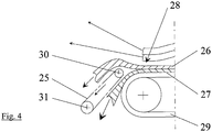
4 : eine Variante.
-
1 : a side view, -
2nd : a top view, -
3rd : an enlarged, side view of the end of a conveyor belt and -
4th : a variant.
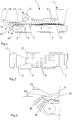
Die Vorrichtung
In Transportrichtung
Nachfolgend erfolgt eine Verdichtung der unteren, schweren Schuttschicht
Am Ende
Eine Variante zeigt
Zweckmäßigerweise wird das Förderband
BezugszeichenlisteReference symbol list
- 1.1.
- Vorrichtungcontraption
- 2.2nd
- FörderbandConveyor belt
- 3.3rd
- AufbringvorrichtungApplicator
- 4.4th
- SchuttschichtRubble layer
- 5.5.
- TransportrichtungDirection of transport
- 6. 6.
- ZinkenTines
- 7.7.
- schwere Schuttschichtheavy layer of rubble
- 8.8th.
- leichte Schuttschichtlight layer of rubble
- 9.9.
- RüttelplatteVibrating plate
- 10.10th
- EndeThe End
- 11.11.
- BlasvorrichtungBlowing device
- 12.12.
- Gebläsefan
- 13.13.
- Düsejet
- 14.14.
- LuftstromAirflow
- 15.15.
- Komponentecomponent
- 16.16.
- Komponentecomponent
- 17.17th
- TrennscheitelParting
- 21.21st
- Düsejet
- 22.22.
- Düsejet
- 23.23.
- LuftstromAirflow
- 24.24th
- LuftstromAirflow
- 25.25th
- FörderbandConveyor belt
- 26.26.
- SchuttschichtRubble layer
- 27.27th
- SchuttschichtRubble layer
- 28.28
- EndeThe End
- 29.29.
- FörderbandConveyor belt
- 30.30th
- Rollerole
- 31.31
- AntriebsrolleDrive roller
ZITATE ENTHALTEN IN DER BESCHREIBUNG QUOTES INCLUDE IN THE DESCRIPTION
Diese Liste der vom Anmelder aufgeführten Dokumente wurde automatisiert erzeugt und ist ausschließlich zur besseren Information des Lesers aufgenommen. Die Liste ist nicht Bestandteil der deutschen Patent- bzw. Gebrauchsmusteranmeldung. Das DPMA übernimmt keinerlei Haftung für etwaige Fehler oder Auslassungen.This list of documents listed by the applicant has been generated automatically and is only included for the better information of the reader. The list is not part of the German patent or utility model application. The DPMA assumes no liability for any errors or omissions.
Zitierte PatentliteraturPatent literature cited
- WO 9625246 [0004]WO 9625246 [0004]
- DE 102004050026 A1 [0004]DE 102004050026 A1 [0004]
Claims (10)
Priority Applications (1)
| Application Number | Priority Date | Filing Date | Title |
|---|---|---|---|
| DE102018009801.0A DE102018009801B4 (en) | 2018-12-18 | 2018-12-18 | Apparatus and method for separating debris |
Applications Claiming Priority (1)
| Application Number | Priority Date | Filing Date | Title |
|---|---|---|---|
| DE102018009801.0A DE102018009801B4 (en) | 2018-12-18 | 2018-12-18 | Apparatus and method for separating debris |
Publications (2)
| Publication Number | Publication Date |
|---|---|
| DE102018009801A1 true DE102018009801A1 (en) | 2020-06-18 |
| DE102018009801B4 DE102018009801B4 (en) | 2022-09-15 |
Family
ID=70858339
Family Applications (1)
| Application Number | Title | Priority Date | Filing Date |
|---|---|---|---|
| DE102018009801.0A Active DE102018009801B4 (en) | 2018-12-18 | 2018-12-18 | Apparatus and method for separating debris |
Country Status (1)
| Country | Link |
|---|---|
| DE (1) | DE102018009801B4 (en) |
Cited By (2)
| Publication number | Priority date | Publication date | Assignee | Title |
|---|---|---|---|---|
| EP4049765A1 (en) * | 2021-02-24 | 2022-08-31 | Kleemann GmbH | Mobile machine for treating bulk material with movable component support over a conveyor path |
| CN115121484A (en) * | 2022-08-05 | 2022-09-30 | 江西农业大学 | A kind of Camellia oleifera seed screening device and method |
Citations (3)
| Publication number | Priority date | Publication date | Assignee | Title |
|---|---|---|---|---|
| CH655254A5 (en) * | 1985-06-12 | 1986-04-15 | T U C Consult Ag | Process and system for treating mixed construction debris |
| WO1996025246A1 (en) | 1995-02-17 | 1996-08-22 | Rethmann Kreislaufwirtschaft Gmbh & Co. Kg | Process and device for sorting waste material, especially mixed waste material from construction |
| DE102004050026A1 (en) | 2004-10-13 | 2006-04-20 | Stadler Anlagenbau Gmbh | Method for sorting of building waste and / or rubble |
-
2018
- 2018-12-18 DE DE102018009801.0A patent/DE102018009801B4/en active Active
Patent Citations (3)
| Publication number | Priority date | Publication date | Assignee | Title |
|---|---|---|---|---|
| CH655254A5 (en) * | 1985-06-12 | 1986-04-15 | T U C Consult Ag | Process and system for treating mixed construction debris |
| WO1996025246A1 (en) | 1995-02-17 | 1996-08-22 | Rethmann Kreislaufwirtschaft Gmbh & Co. Kg | Process and device for sorting waste material, especially mixed waste material from construction |
| DE102004050026A1 (en) | 2004-10-13 | 2006-04-20 | Stadler Anlagenbau Gmbh | Method for sorting of building waste and / or rubble |
Cited By (4)
| Publication number | Priority date | Publication date | Assignee | Title |
|---|---|---|---|---|
| EP4049765A1 (en) * | 2021-02-24 | 2022-08-31 | Kleemann GmbH | Mobile machine for treating bulk material with movable component support over a conveyor path |
| US11753252B2 (en) | 2021-02-24 | 2023-09-12 | Kleemann Gmbh | Mobile machine for handling aggregate material having a movable component carrier above a conveyor line |
| CN115121484A (en) * | 2022-08-05 | 2022-09-30 | 江西农业大学 | A kind of Camellia oleifera seed screening device and method |
| CN115121484B (en) * | 2022-08-05 | 2023-10-10 | 江西农业大学 | Tea-oil camellia Pu Zi screening device and method |
Also Published As
| Publication number | Publication date |
|---|---|
| DE102018009801B4 (en) | 2022-09-15 |
Similar Documents
| Publication | Publication Date | Title |
|---|---|---|
| DE2857321C2 (en) | Process for spraying a monolithic refractory material | |
| DE19835419A1 (en) | Diffuser for layering prepared particles prior to bonding has several perforated screens over a sloping wall to evenly spread the particles and to prevent clogging | |
| DE102018009801B4 (en) | Apparatus and method for separating debris | |
| WO1999061174A1 (en) | Separating device for longitudinally extended solid material parts | |
| DE3626053C2 (en) | ||
| DE2311308C3 (en) | Device for separating spherical particles from fibers, film strips and the like | |
| DE102011016343A1 (en) | Method for adjusting basis weight of scattered bulk material on conveyor belt during manufacturing fiber board, involves controlling and compacting web in portions along flow direction according to intended basis weight distribution | |
| EP0069162A1 (en) | Method and apparatus for controlling the density distribution of a dispersed particle mat | |
| DE60223678T2 (en) | DEVICE FOR DISTRIBUTING ADHESIVE MATERIAL | |
| WO2000020181A1 (en) | Dispersing station | |
| WO2018011430A1 (en) | Scattering installation and method for producing a mat of scattered material during the course of the production of material panels | |
| DE1558919C3 (en) | Method and device for continuous length sorting of fibers | |
| EP0111025B1 (en) | Device for the production of particle board | |
| DE2809019C3 (en) | Device for the electrostatic alignment and application of fibers on a surface | |
| DE1214370C2 (en) | Dust removal device, especially for paint booths | |
| DE10261292B4 (en) | Reservoir for powdered media | |
| DE1929465A1 (en) | Device for the production of wood fiber boards | |
| DE202004017134U1 (en) | Equipment producing melt-blown fleece has nozzle above conveying- and deposition surface, with intervening air guidance system | |
| DE2926087A1 (en) | Orientating chips for chipboard prodn. - where stream of chips falls between vibrating and fixed vertical plates to conveyor | |
| WO2004044476A1 (en) | Wall of a device for the transport of liquid or gaseous media charged with abrasive particles | |
| DE2535461C3 (en) | Device for spreading mat grit on a continuously moving spreading mat | |
| DE102016014268A1 (en) | Device and method for separating pressed material mats | |
| DE102019115358A1 (en) | Device and method for the production of a fleece as well as a system for the production of fiber-reinforced resin mats | |
| DE102004054214A1 (en) | Hotmelt process and assembly for the production of polymer fleece material has anti-turbulence air guidance units | |
| EP3970867A2 (en) | Wind scattering device |
Legal Events
| Date | Code | Title | Description |
|---|---|---|---|
| R163 | Identified publications notified | ||
| R012 | Request for examination validly filed | ||
| R018 | Grant decision by examination section/examining division | ||
| R081 | Change of applicant/patentee |
Owner name: REMA ANLAGENBAU GMBH, DE Free format text: FORMER OWNER: SCHLUETER, FRIEDRICH-WILHELM, 32657 LEMGO, DE |
|
| R020 | Patent grant now final |