DE102017119552B3 - Belt tensioner and belt drive with it - Google Patents
Belt tensioner and belt drive with it Download PDFInfo
- Publication number
- DE102017119552B3 DE102017119552B3 DE102017119552.1A DE102017119552A DE102017119552B3 DE 102017119552 B3 DE102017119552 B3 DE 102017119552B3 DE 102017119552 A DE102017119552 A DE 102017119552A DE 102017119552 B3 DE102017119552 B3 DE 102017119552B3
- Authority
- DE
- Germany
- Prior art keywords
- arm
- belt tensioner
- drive
- drive belt
- belt
- Prior art date
- Legal status (The legal status is an assumption and is not a legal conclusion. Google has not performed a legal analysis and makes no representation as to the accuracy of the status listed.)
- Expired - Fee Related
Links
- 238000006243 chemical reaction Methods 0.000 claims description 8
- 230000006835 compression Effects 0.000 claims description 2
- 238000007906 compression Methods 0.000 claims description 2
- 230000000694 effects Effects 0.000 claims description 2
- 230000005540 biological transmission Effects 0.000 claims 1
- 230000007935 neutral effect Effects 0.000 claims 1
- 230000008878 coupling Effects 0.000 description 5
- 238000010168 coupling process Methods 0.000 description 5
- 238000005859 coupling reaction Methods 0.000 description 5
- 210000001520 comb Anatomy 0.000 description 2
- 230000002349 favourable effect Effects 0.000 description 2
- 238000004519 manufacturing process Methods 0.000 description 2
- 238000010276 construction Methods 0.000 description 1
- 230000007423 decrease Effects 0.000 description 1
Images


Classifications
-
- F—MECHANICAL ENGINEERING; LIGHTING; HEATING; WEAPONS; BLASTING
- F16—ENGINEERING ELEMENTS AND UNITS; GENERAL MEASURES FOR PRODUCING AND MAINTAINING EFFECTIVE FUNCTIONING OF MACHINES OR INSTALLATIONS; THERMAL INSULATION IN GENERAL
- F16H—GEARING
- F16H7/00—Gearings for conveying rotary motion by endless flexible members
- F16H7/08—Means for varying tension of belts, ropes or chains
- F16H7/10—Means for varying tension of belts, ropes or chains by adjusting the axis of a pulley
- F16H7/12—Means for varying tension of belts, ropes or chains by adjusting the axis of a pulley of an idle pulley
- F16H7/1254—Means for varying tension of belts, ropes or chains by adjusting the axis of a pulley of an idle pulley without vibration damping means
- F16H7/1281—Means for varying tension of belts, ropes or chains by adjusting the axis of a pulley of an idle pulley without vibration damping means where the axis of the pulley moves along a substantially circular path
-
- F—MECHANICAL ENGINEERING; LIGHTING; HEATING; WEAPONS; BLASTING
- F16—ENGINEERING ELEMENTS AND UNITS; GENERAL MEASURES FOR PRODUCING AND MAINTAINING EFFECTIVE FUNCTIONING OF MACHINES OR INSTALLATIONS; THERMAL INSULATION IN GENERAL
- F16H—GEARING
- F16H7/00—Gearings for conveying rotary motion by endless flexible members
- F16H7/02—Gearings for conveying rotary motion by endless flexible members with belts; with V-belts
-
- F—MECHANICAL ENGINEERING; LIGHTING; HEATING; WEAPONS; BLASTING
- F16—ENGINEERING ELEMENTS AND UNITS; GENERAL MEASURES FOR PRODUCING AND MAINTAINING EFFECTIVE FUNCTIONING OF MACHINES OR INSTALLATIONS; THERMAL INSULATION IN GENERAL
- F16H—GEARING
- F16H7/00—Gearings for conveying rotary motion by endless flexible members
- F16H7/08—Means for varying tension of belts, ropes or chains
- F16H7/10—Means for varying tension of belts, ropes or chains by adjusting the axis of a pulley
- F16H7/12—Means for varying tension of belts, ropes or chains by adjusting the axis of a pulley of an idle pulley
-
- F—MECHANICAL ENGINEERING; LIGHTING; HEATING; WEAPONS; BLASTING
- F16—ENGINEERING ELEMENTS AND UNITS; GENERAL MEASURES FOR PRODUCING AND MAINTAINING EFFECTIVE FUNCTIONING OF MACHINES OR INSTALLATIONS; THERMAL INSULATION IN GENERAL
- F16H—GEARING
- F16H7/00—Gearings for conveying rotary motion by endless flexible members
- F16H7/08—Means for varying tension of belts, ropes or chains
- F16H2007/0802—Actuators for final output members
- F16H2007/0806—Compression coil springs
-
- F—MECHANICAL ENGINEERING; LIGHTING; HEATING; WEAPONS; BLASTING
- F16—ENGINEERING ELEMENTS AND UNITS; GENERAL MEASURES FOR PRODUCING AND MAINTAINING EFFECTIVE FUNCTIONING OF MACHINES OR INSTALLATIONS; THERMAL INSULATION IN GENERAL
- F16H—GEARING
- F16H7/00—Gearings for conveying rotary motion by endless flexible members
- F16H7/08—Means for varying tension of belts, ropes or chains
- F16H2007/0802—Actuators for final output members
- F16H2007/0808—Extension coil springs
-
- F—MECHANICAL ENGINEERING; LIGHTING; HEATING; WEAPONS; BLASTING
- F16—ENGINEERING ELEMENTS AND UNITS; GENERAL MEASURES FOR PRODUCING AND MAINTAINING EFFECTIVE FUNCTIONING OF MACHINES OR INSTALLATIONS; THERMAL INSULATION IN GENERAL
- F16H—GEARING
- F16H7/00—Gearings for conveying rotary motion by endless flexible members
- F16H7/08—Means for varying tension of belts, ropes or chains
- F16H2007/0842—Mounting or support of tensioner
-
- F—MECHANICAL ENGINEERING; LIGHTING; HEATING; WEAPONS; BLASTING
- F16—ENGINEERING ELEMENTS AND UNITS; GENERAL MEASURES FOR PRODUCING AND MAINTAINING EFFECTIVE FUNCTIONING OF MACHINES OR INSTALLATIONS; THERMAL INSULATION IN GENERAL
- F16H—GEARING
- F16H7/00—Gearings for conveying rotary motion by endless flexible members
- F16H7/08—Means for varying tension of belts, ropes or chains
- F16H2007/0863—Finally actuated members, e.g. constructional details thereof
- F16H2007/0865—Pulleys
-
- F—MECHANICAL ENGINEERING; LIGHTING; HEATING; WEAPONS; BLASTING
- F16—ENGINEERING ELEMENTS AND UNITS; GENERAL MEASURES FOR PRODUCING AND MAINTAINING EFFECTIVE FUNCTIONING OF MACHINES OR INSTALLATIONS; THERMAL INSULATION IN GENERAL
- F16H—GEARING
- F16H7/00—Gearings for conveying rotary motion by endless flexible members
- F16H7/08—Means for varying tension of belts, ropes or chains
- F16H2007/0889—Path of movement of the finally actuated member
- F16H2007/0893—Circular path
-
- F—MECHANICAL ENGINEERING; LIGHTING; HEATING; WEAPONS; BLASTING
- F16—ENGINEERING ELEMENTS AND UNITS; GENERAL MEASURES FOR PRODUCING AND MAINTAINING EFFECTIVE FUNCTIONING OF MACHINES OR INSTALLATIONS; THERMAL INSULATION IN GENERAL
- F16H—GEARING
- F16H7/00—Gearings for conveying rotary motion by endless flexible members
- F16H7/08—Means for varying tension of belts, ropes or chains
- F16H2007/0889—Path of movement of the finally actuated member
- F16H2007/0897—External to internal direction
Landscapes
- Engineering & Computer Science (AREA)
- General Engineering & Computer Science (AREA)
- Mechanical Engineering (AREA)
- Devices For Conveying Motion By Means Of Endless Flexible Members (AREA)
Abstract
Die Erfindung betrifft einen Treibriemen-Spanner (18) mit (a) einem Gehäuse (20), (b) einem Satz Tellerfedern (42), (c) einem Spannarm (22), der mit den Tellerfedern (42) zum Komprimieren der Tellerfedern (42) beim Bewegen des eine Auslenkrichtung (A) aus einer Nullstellung heraus verbunden ist. Erfindungsgemäß vorgesehen ist ein zweiter Satz Tellerfedern (44), wobei der Spannarm (22) mit den Tellerfedern (44) des zweiten Satzes zum Komprimieren beim Bewegen des Spannarms (22) in eine zur Auslenkrichtung (A) entgegengesetzte Gegenrichtung (G) aus der Nullstellung heraus verbunden ist.The invention relates to a drive belt tensioner (18) having (a) a housing (20), (b) a set of disc springs (42), (c) a tensioning arm (22) connected to the disc springs (42) for compressing the disc springs (42) when moving the one deflection (A) is connected from a zero position out. According to the invention, a second set of disk springs (44) is provided, wherein the clamping arm (22) with the disk springs (44) of the second set for compressing when moving the clamping arm (22) in a direction opposite to the deflection (A) opposite direction (G) from the zero position is connected out.
Description
Die Erfindung betrifft einen Treibriemen-Spanner mit einem Gehäuse, einem Satz Tellerfedern und einem Spannarm, der mit den Tellerfedern zum Komprimieren der Tellerfedern beim Bewegen des Spannarms relativ zum Gehäuse in eine Auslenkrichtung aus einer Nullstellung heraus verbunden ist. Ein derartiger Treibriemen-Spanner ist aus der
Derartige Treibriemen-Spanner sind Standardbauteile und werden in einer Vielzahl unterschiedlicher Riementriebe verwendet. Es ist daher wünschenswert, Treibriemen-Spanner so auszubilden, dass er für eine möglichst große Vielzahl an Riementrieben verwendet werden kann.Such belt tensioners are standard components and are used in a variety of belt drives. It is therefore desirable to design drive belt tensioners such that they can be used for the widest possible variety of belt drives.
Der Erfindung liegt die Aufgabe zugrunde, Nachteile im Stand der Technik zu vermindern.The invention has for its object to reduce disadvantages in the prior art.
Die Erfindung löst das Problem durch einen gattungsgemäßen Treibriemen-Spanner, der einen zweiten Satz Tellerfedern aufweist, wobei der Spannarm mit den Tellerfedern des zweiten Satzes zum Komprimieren der Tellerfedern des zweiten Satzes beim Bewegen des Spannarms in eine zur Auslenkrichtung entgegengesetzte Gegenrichtung aus der Nullstellung relativ zum Gehäuse heraus verbunden ist.The invention solves the problem by a generic belt tensioner having a second set of disc springs, wherein the clamping arm with the plate springs of the second set for compressing the plate springs of the second set when moving the clamping arm in a direction opposite to the opposite direction from the zero position relative to Housing is connected out.
Vorteilhaft an diesem Treibriemen-Spanner ist, dass bei einer Auslenkung sowohl in Auslenkrichtung als auch in die Gegenrichtung eine Rückstellkraft erzeugt wird. Der Treibriemen-Spanner könnte damit sowohl in solchen Riementrieben angewendet werden, in denen eine Spannkraft bei Auslenkung in Auslenkrichtung benötigt wird, als auch in solchen Riementrieben, bei denen eine Rückstellkraft bei Auslenkung in Gegenrichtung gewünscht ist. Im Vergleich zum bekannten Treibriemen-Spanner kann so die Produktvielfalt an Treibriemen-Spannern reduziert werden.An advantage of this belt tensioner is that in a deflection in both the deflection and in the opposite direction, a restoring force is generated. The belt tensioner could thus be applied both in such belt drives, in which a clamping force is required for deflection in deflection, as well as in those belt drives, in which a restoring force is desired for deflection in the opposite direction. In comparison to the known belt tensioner so the product variety can be reduced to drive belt tensioners.
Vorteilhaft ist zudem, dass der erfindungsgemäße Treibriemen-Spanner einfach aufgebaut und damit leicht zu fertigen ist.It is also advantageous that the drive belt tensioner according to the invention is simple in construction and thus easy to manufacture.
Vorteilhaft ist zudem, dass der Treibriemen-Spanner so gebaut werden kann, dass er verschleißarm ist.Another advantage is that the belt tensioner can be built so that it is wear.
Im erfindungsgemäßen Treibriemen-Spanner arbeiten der erste Satz an Tellerfedern und der zweite Satz an Tellerfedern antagonistisch zueinander. Da Tellerfedern gemäß einer bevorzugten Ausführungsform so ausgebildet werden können, dass sie einen ausgeprägten Hookeschen Bereich haben, der sich insbesondere über einen Auslenkwinkel von 0° bis zumindest 25° erstreckt, ergibt sich bei Auslenkung aus der Nulllage eine Rückstellkraft, die mit zunehmender Auslenkung proportional ansteigt. Eine derartige Charakteristik ist zum Spannen von Treibriemen besonders geeignet. Bei Treibriemen-Spannern, die Gummielemente verwenden, steigt die Federsteifigkeit hingegen oft mit zunehmender Auslenkung an.In the drive belt tensioner according to the invention, the first set of disc springs and the second set of disc springs work antagonistically to each other. Since disc springs according to a preferred embodiment can be formed so that they have a pronounced Hooke's area, which extends in particular over a deflection angle of 0 ° to at least 25 °, results in deflection from the zero position a restoring force, which increases proportionally with increasing deflection , Such a characteristic is particularly suitable for tensioning drive belts. In the case of belt tensioners using rubber elements, on the other hand, the spring stiffness often increases with increasing deflection.
Vorzugsweise besitzt der Treibriemen-Spanner eine Spannrolle, die am Spannarm befestigt ist und eingerichtet ist zum Zusammenwirken mit einem Treibriemen.Preferably, the drive belt tensioner has a tension roller which is fixed to the tensioning arm and is adapted to cooperate with a drive belt.
Günstig ist es, wenn der Treibriemen-Spanner ein Umsetzelement aufweist, das drehfest mit dem Spannarm verbunden ist und ein Gewinde aufweist, wobei das Gehäuse einen Vorsprung aufweist, der mit dem Gewinde in Eingriff steht und wobei der Vorsprung und das Umsetzelement ausgebildet sind zum Bewirken des Komprimierens von Tellerfedern beim Bewegen des Spannarms aus der Nullstellung heraus. Insbesondere ist das Umsetzelement ausgebildet zum Komprimieren des Satzes an Tellerfedern, wenn der Spannarm in die Auslenkung aus der Nullstellung heraus bewegt wird und zum Komprimieren des zweiten Satzes an Tellerfedern, wenn der Spannarm in die Gegenrichtung aus der Nullstellung heraus bewegt wird. In anderen Worten ist das Umsetzelement ausgebildet zum Umsetzen einer Drehbewegung in eine lineare Bewegung, wobei die Tellerfedern durch eine lineare Bewegung zusammengedrückt werden.It is advantageous if the drive belt tensioner has a transfer element which is non-rotatably connected to the clamping arm and has a thread, wherein the housing has a projection which is in engagement with the thread and wherein the projection and the conversion element are formed to effect Compressing Belleville springs when moving the clamp arm out of the zero position. In particular, the translation element is configured to compress the set of Belleville washers as the clamp arm is moved into the deflection out of the null position and to compress the second set of Belleville washers as the clamp arm is moved in the opposite direction out of the null position. In other words, the translating element is configured to translate a rotary motion into a linear motion, compressing the cup springs by a linear motion.
Günstig ist es, wenn das Gewinde eine konstante Steigung hat. Ein derartiges Gewinde ist besonders einfach zu fertigen.It is favorable if the thread has a constant pitch. Such a thread is particularly easy to manufacture.
Alternativ hat das Gewinde eine Steigung, die sich zumindest abschnittsweise mit einer Auslenkung des Spannarms von der Nullstellung ändert. Insbesondere ist es möglich, dass die Steigung sich mit der Auslenkung des Spannarms von der Nullstellung verringert, sodass die mit zunehmender Kompression zunehmende Federkonstante der Tellerfedern zumindest teilweise kompensiert wird.Alternatively, the thread has a slope that changes at least in sections with a deflection of the clamping arm from the zero position. In particular, it is possible that the slope decreases with the deflection of the tensioning arm from the zero position, so that the increasing with increasing compression spring constant of the disc springs is at least partially compensated.
Vorzugsweise ist die Spannrolle mittels eines Lochs in einem ersten Abstand von einer Drehachse des Spannarms am Spannarm befestigt, wobei der Spannarm ein zweites Loch zum Befestigen der Spannrolle in einem vom ersten Abstand verschiedenen, zweiten Abstand hat. Auf diese Weise existiert eine zweite Möglichkeit, die Spannkraft zu verändern, indem nämlich die Spannrolle in einem abweichenden Abstand zur Drehachse befestigt wird.Preferably, the tensioning roller is secured to the tensioning arm by means of a hole at a first distance from an axis of rotation of the tensioning arm, the tensioning arm having a second hole for securing the tensioning roller in a second distance different from the first distance. In this way, there is a second way to change the clamping force, namely by the tension roller is fixed at a different distance from the axis of rotation.
Im Folgenden wird die Erfindung anhand der beigefügten Zeichnungen näher erläutert. Dabei zeigt
-
1 eine schematische Ansicht eines erfindungsgemäßen Riementriebs, -
2 einen erfindungsgemäßen Treibriemen-Spanner für einen Riementrieb gemäß1 , -
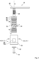
3 einen Querschnitt durch den Riementrieb-Spanner gemäß2 und -
4 eine Explosionszeichnung des Treibriemen-Spanners gemäß2 .
-
1 a schematic view of a belt drive according to the invention, -
2 a belt tensioner according to the invention for a belt drive according to1 . -
3 a cross section through the belt drive tensioner according to2 and -
4 an exploded view of the belt tensioner according to2 ,
Der Treibriemen-Spanner
Das Gehäuse
Wird der Spannarm
Wird der Spannarm
Es sei darauf hingewiesen, dass jeder Satz an Tellerfedern auch eine einzige Tellerfeder umfassen kann. Günstig ist es jedoch, wenn der erste Satz
Der Spannarm
Das Gehäuse
Zum Montieren des Treibriemen-Spanners an einem schematisch angezeichneten Bauteil
Ist die korrekte Spannkraft
BezugszeichenlisteLIST OF REFERENCE NUMBERS
- 1010
- Riementriebbelt drive
- 1212
- Antriebs-RiemenradDrive pulley
- 1414
- Abtriebs-RiemenradOutput drive pulley
- 1616
- Treibriemenbelts
- 1818
- Treibriemen-Spanner Drive belt tensioner
- 2020
- Gehäusecasing
- 2222
- Spannarmclamping arm
- 2424
- Spannrolleidler
- 2626
- erstes Lochfirst hole
- 2828
- zweites Loch second hole
- 3030
- Fußfoot
- 3232
- Umsetzelementconversion element
- 3434
- Gewindethread
- 3636
- Innenverzahnunginternal gearing
- 3838
- Außenverzahnung external teeth
- 4040
- Vorsprunghead Start
- 4242
- erster Satz Tellerfedernfirst set of cup springs
- 4444
- zweiter Satz Tellerfedernsecond set of cup springs
- 4646
- Unterlegscheibewasher
- 4848
- Rückhaltering Retaining ring
- 5050
- HalteplatteRetaining plate
- 5252
- Dichtungpoetry
- 5454
- Schraubescrew
- 5656
- Koppelstrukturcoupling structure
- 56a, b56a, b
- Flächensurfaces
- 5858
- Bauteil component
- αα
- Auslenkwinkelangle of deflection
- σσ
- Steigungswinkellead angle
- AA
- Auslenkrichtungdeflection
- DD
- Drehachseaxis of rotation
- FF
- Spannkrafttension
- GG
- Gegenrichtungopposite direction
- SS
- Steigungpitch
- dd
- Abstanddistance
Claims (7)
Priority Applications (3)
| Application Number | Priority Date | Filing Date | Title |
|---|---|---|---|
| DE102017119552.1A DE102017119552B3 (en) | 2017-08-25 | 2017-08-25 | Belt tensioner and belt drive with it |
| EP18189617.6A EP3447332B1 (en) | 2017-08-25 | 2018-08-17 | Drive belt tensioner and belt drive using the same |
| US16/110,219 US10907704B2 (en) | 2017-08-25 | 2018-08-23 | Transmission belt tensioner and associated belt drive |
Applications Claiming Priority (1)
| Application Number | Priority Date | Filing Date | Title |
|---|---|---|---|
| DE102017119552.1A DE102017119552B3 (en) | 2017-08-25 | 2017-08-25 | Belt tensioner and belt drive with it |
Publications (1)
| Publication Number | Publication Date |
|---|---|
| DE102017119552B3 true DE102017119552B3 (en) | 2018-05-09 |
Family
ID=62003413
Family Applications (1)
| Application Number | Title | Priority Date | Filing Date |
|---|---|---|---|
| DE102017119552.1A Expired - Fee Related DE102017119552B3 (en) | 2017-08-25 | 2017-08-25 | Belt tensioner and belt drive with it |
Country Status (3)
| Country | Link |
|---|---|
| US (1) | US10907704B2 (en) |
| EP (1) | EP3447332B1 (en) |
| DE (1) | DE102017119552B3 (en) |
Families Citing this family (2)
| Publication number | Priority date | Publication date | Assignee | Title |
|---|---|---|---|---|
| KR20200105922A (en) * | 2018-01-31 | 2020-09-09 | 보르그워너 인코퍼레이티드 | Variable force tensioner arm with cap disc spring |
| IT202000015877A1 (en) * | 2020-07-01 | 2022-01-01 | Dayco Europe Srl | TENSIONER FOR AN ACCESSORY TRANSMISSION OF A MOTOR VEHICLE AND AN ACCESSORY TRANSMISSION EQUIPPED WITH SUCH TENSIONER |
Citations (2)
| Publication number | Priority date | Publication date | Assignee | Title |
|---|---|---|---|---|
| DE2535676A1 (en) * | 1975-08-09 | 1977-02-17 | Porsche Ag | Camshaft drive belt tensioning mechanism - has belt roller on shaft adjusted axially by bolt and thermostat |
| DE3104201A1 (en) | 1979-11-05 | 1982-08-19 | Dyneer Corp., 06880 Westport, Conn. | DEVICE FOR TENSIONING A DRIVE BELT OF VEHICLE ENGINES |
Family Cites Families (7)
| Publication number | Priority date | Publication date | Assignee | Title |
|---|---|---|---|---|
| US4270906A (en) * | 1979-11-05 | 1981-06-02 | Dyneer Corporation | Belt tensioner construction |
| DE3836933A1 (en) * | 1988-05-21 | 1990-05-10 | Schaeffler Waelzlager Kg | Tension device for belts |
| US4969858A (en) * | 1988-10-29 | 1990-11-13 | Ina Walzlager Schaeffler Kg | Tensioning device for belts |
| CA2074637C (en) * | 1991-07-31 | 1998-11-10 | Kazuki Kawashima | Belt tension adjusting device |
| US5277666A (en) * | 1991-10-21 | 1994-01-11 | Kumm Industries, Inc. | Belt tensioner |
| DE102008046425A1 (en) * | 2008-09-09 | 2010-03-11 | Schaeffler Kg | Automatic traction mechanism clamping device i.e. mechanical belt tension adjuster, for belt drive of internal combustion engine of motor vehicle, has damping unit with friction ring that cooperates with disk spring element i.e. ring shell |
| FR3008156B1 (en) * | 2013-07-02 | 2015-08-07 | Skf Ab | TENSIONER DEVICE OF A TRACTION MEMBER, MOTOR EQUIPPED WITH SUCH TENDERING DEVICE AND METHOD OF IMPLEMENTING THE SAME |
-
2017
- 2017-08-25 DE DE102017119552.1A patent/DE102017119552B3/en not_active Expired - Fee Related
-
2018
- 2018-08-17 EP EP18189617.6A patent/EP3447332B1/en not_active Not-in-force
- 2018-08-23 US US16/110,219 patent/US10907704B2/en not_active Expired - Fee Related
Patent Citations (2)
| Publication number | Priority date | Publication date | Assignee | Title |
|---|---|---|---|---|
| DE2535676A1 (en) * | 1975-08-09 | 1977-02-17 | Porsche Ag | Camshaft drive belt tensioning mechanism - has belt roller on shaft adjusted axially by bolt and thermostat |
| DE3104201A1 (en) | 1979-11-05 | 1982-08-19 | Dyneer Corp., 06880 Westport, Conn. | DEVICE FOR TENSIONING A DRIVE BELT OF VEHICLE ENGINES |
Also Published As
| Publication number | Publication date |
|---|---|
| EP3447332A1 (en) | 2019-02-27 |
| EP3447332B1 (en) | 2020-09-30 |
| US20190063564A1 (en) | 2019-02-28 |
| US10907704B2 (en) | 2021-02-02 |
Similar Documents
| Publication | Publication Date | Title |
|---|---|---|
| DE2826274C2 (en) | Elastic coupling | |
| DE19681672B4 (en) | Friction torque hinge with clamp | |
| DE102010021536B4 (en) | Spindle drive | |
| DE4213429A1 (en) | CLAMPING DEVICE | |
| DE102016111324A1 (en) | jig | |
| EP1989467A1 (en) | Toothed wheel arrangement | |
| DE102017119552B3 (en) | Belt tensioner and belt drive with it | |
| DE102008043476A1 (en) | Ball screw module | |
| DE2630627A1 (en) | DEVICE FOR PRELOADING WITH LIMITED FORCE, IN PARTICULAR FOR BELT TENSIONERS | |
| DE10337427A1 (en) | Dirt stripping apparatus for conveyor belt assembly, has stripping unit including lamella that contacts belt in peeling position, and lamella is swivel mounted at lamella holder by top swivel mount having horizontal swivel axis | |
| DE102014221904B4 (en) | 1-motor transmission actuator for a motor vehicle transmission device | |
| EP2735535A1 (en) | Thread guide unit, motion damper for a thread guide unit and method for producing the motion damper | |
| DE10236753A1 (en) | Planet wheel carrier, for a motor vehicle gearbox, has a locking ring at the axis bearing against movement in one axial direction and a spring lock acting against the other axial direction | |
| EP2362494A1 (en) | Connector | |
| DE102014222755A1 (en) | Bearing concept for spindle of a wear adjustment | |
| DE102016117606B4 (en) | Belt drive | |
| DE102019107684A1 (en) | Ball screw | |
| DE102023102778A1 (en) | DRIVE MECHANISM | |
| DE102020130665B4 (en) | 1 - 17Shut-off clutch | |
| DE10315219A1 (en) | Ball screw has intermediate elements with spring sections elastically constructed in axial direction acting against respectively adjacent balls and formed around central non-sprung section | |
| DE102007023648A1 (en) | Cylindrical dynamic damper | |
| DE102014216851B4 (en) | Freewheel device with friction-minimized freewheel function | |
| DE202011050291U1 (en) | spring element | |
| EP0132671A2 (en) | Pulse generator | |
| DE202015103946U1 (en) | Electrical connector with release protection |
Legal Events
| Date | Code | Title | Description |
|---|---|---|---|
| R012 | Request for examination validly filed | ||
| R016 | Response to examination communication | ||
| R018 | Grant decision by examination section/examining division | ||
| R020 | Patent grant now final | ||
| R119 | Application deemed withdrawn, or ip right lapsed, due to non-payment of renewal fee | ||
| R082 | Change of representative |
Representative=s name: MEISSNER BOLTE PATENTANWAELTE RECHTSANWAELTE P, DE |