DE102016221663A1 - Crushing plant with a crusher - Google Patents
Crushing plant with a crusher Download PDFInfo
- Publication number
- DE102016221663A1 DE102016221663A1 DE102016221663.5A DE102016221663A DE102016221663A1 DE 102016221663 A1 DE102016221663 A1 DE 102016221663A1 DE 102016221663 A DE102016221663 A DE 102016221663A DE 102016221663 A1 DE102016221663 A1 DE 102016221663A1
- Authority
- DE
- Germany
- Prior art keywords
- traversing device
- crushing
- housing wall
- rail
- machine
- Prior art date
- Legal status (The legal status is an assumption and is not a legal conclusion. Google has not performed a legal analysis and makes no representation as to the accuracy of the status listed.)
- Withdrawn
Links
Images

Classifications
-
- B—PERFORMING OPERATIONS; TRANSPORTING
- B02—CRUSHING, PULVERISING, OR DISINTEGRATING; PREPARATORY TREATMENT OF GRAIN FOR MILLING
- B02C—CRUSHING, PULVERISING, OR DISINTEGRATING IN GENERAL; MILLING GRAIN
- B02C4/00—Crushing or disintegrating by roller mills
- B02C4/28—Details
-
- B—PERFORMING OPERATIONS; TRANSPORTING
- B02—CRUSHING, PULVERISING, OR DISINTEGRATING; PREPARATORY TREATMENT OF GRAIN FOR MILLING
- B02C—CRUSHING, PULVERISING, OR DISINTEGRATING IN GENERAL; MILLING GRAIN
- B02C18/00—Disintegrating by knives or other cutting or tearing members which chop material into fragments
- B02C18/06—Disintegrating by knives or other cutting or tearing members which chop material into fragments with rotating knives
- B02C18/14—Disintegrating by knives or other cutting or tearing members which chop material into fragments with rotating knives within horizontal containers
- B02C18/142—Disintegrating by knives or other cutting or tearing members which chop material into fragments with rotating knives within horizontal containers with two or more inter-engaging rotatable cutter assemblies
-
- B—PERFORMING OPERATIONS; TRANSPORTING
- B02—CRUSHING, PULVERISING, OR DISINTEGRATING; PREPARATORY TREATMENT OF GRAIN FOR MILLING
- B02C—CRUSHING, PULVERISING, OR DISINTEGRATING IN GENERAL; MILLING GRAIN
- B02C23/00—Auxiliary methods or auxiliary devices or accessories specially adapted for crushing or disintegrating not provided for in preceding groups or not specially adapted to apparatus covered by a single preceding group
-
- B—PERFORMING OPERATIONS; TRANSPORTING
- B66—HOISTING; LIFTING; HAULING
- B66F—HOISTING, LIFTING, HAULING OR PUSHING, NOT OTHERWISE PROVIDED FOR, e.g. DEVICES WHICH APPLY A LIFTING OR PUSHING FORCE DIRECTLY TO THE SURFACE OF A LOAD
- B66F3/00—Devices, e.g. jacks, adapted for uninterrupted lifting of loads
- B66F3/24—Devices, e.g. jacks, adapted for uninterrupted lifting of loads fluid-pressure operated
- B66F3/25—Constructional features
- B66F3/36—Load-engaging elements
-
- B—PERFORMING OPERATIONS; TRANSPORTING
- B02—CRUSHING, PULVERISING, OR DISINTEGRATING; PREPARATORY TREATMENT OF GRAIN FOR MILLING
- B02C—CRUSHING, PULVERISING, OR DISINTEGRATING IN GENERAL; MILLING GRAIN
- B02C18/00—Disintegrating by knives or other cutting or tearing members which chop material into fragments
- B02C18/06—Disintegrating by knives or other cutting or tearing members which chop material into fragments with rotating knives
- B02C18/16—Details
- B02C2018/162—Shape or inner surface of shredder-housings
Landscapes
- Engineering & Computer Science (AREA)
- Food Science & Technology (AREA)
- Life Sciences & Earth Sciences (AREA)
- Geology (AREA)
- Mechanical Engineering (AREA)
- Structural Engineering (AREA)
- Crushing And Grinding (AREA)
- Disintegrating Or Milling (AREA)
- Formation And Processing Of Food Products (AREA)
- Filling Or Emptying Of Bunkers, Hoppers, And Tanks (AREA)
Abstract
Die vorliegende Erfindung betrifft eine Zerkleinerungsanlage mit einer Zerkleinerungsmaschine zur Verringerung der Korngröße eines Mineralstoffes, wobei die Zerkleinerungsmaschine ein Maschinengehäuse und wenigstens eine Verfahrvorrichtung aufweist, wobei das Maschinengehäuse wenigstens eine Gehäusewand mit sich zumindest teilweise über eine Breite der Gehäusewand erstreckenden Versteifungsrippen oder in Form einer Bramme aufweist, und wobei die Verfahrvorrichtung an der Gehäusewand befestigt und wechselweise in eine Verfahrstellung, in der die Zerkleinerungsmaschine auf einem Stützelement der Verfahrvorrichtung stehend verfahrbar ist, und in eine Standstellung, in der die Zerkleinerungsmaschine ortsfest steht, bringbar ist. Es ist daher die Aufgabe der Erfhdung, eine Zerkleinerungsanlage mit einer kompakten Verfahrvorrichtung aufzuzeigen, die in kurzen Wartungszeiten verfahrbar ist. Die Aufgabe wird durch gelöst, dass die Gehäusewand wenigstens eine zum Einbau der Verfahrvorrichtung ausgebildete Ausnehmung aufweist, sodass die Verfahrvorrichtung zumindest weitgehend in die Gehäusewand innerhalb deren Breite integrierbar ist, indem sie zumindest teilweise in der Ausnehmung anordenbar ist.The present invention relates to a crushing plant with a crushing machine for reducing the grain size of a mineral, wherein the crushing machine comprises a machine housing and at least one traversing device, wherein the machine housing has at least one housing wall with at least partially over a width of the housing wall extending stiffening ribs or in the form of a slab , and wherein the traversing device attached to the housing wall and alternately in a travel position in which the crushing machine is movable on a support member of the traversing device, and in a stand position in which the crushing machine is stationary, can be brought. It is therefore the object of Erfhdung to show a crushing plant with a compact traversing device that can be moved in short maintenance times. The object is achieved by that the housing wall has at least one recess formed for installation of the traversing device, so that the traversing device can be integrated at least substantially into the housing wall within its width by being at least partially locatable in the recess.
Description
Die vorliegende Erfindung betrifft eine Zerkleinerungsanlage mit einer Zerkleinerungsmaschine, insbesondere Brecheranlage mit einer Brechermaschine oder einem Sizer zur Verringerung der Korngröße eines Mineralstoffes, wobei die Zerkleinerungsmaschine ein Maschinengehäuse und wenigstens eine Verfahrvorrichtung aufweist, wobei das Maschinengehäuse wenigstens eine Gehäusewand mit sich zumindest teilweise über eine Breite der Gehäusewand erstreckenden Versteifungsrippen oder in Form einer Bramme aufweist, und wobei die Verfahrvorrichtung an der Gehäusewand befestigt und wechselweise in eine Verfahrstellung, in der die Zerkleinerungsmaschine auf einem Stützelement der Verfahrvorrichtung stehend verfahrbar ist, und in eine Standstellung, in der die Zerkleinerungsmaschine ortsfest steht, bringbar ist.The present invention relates to a crushing plant with a crushing machine, in particular crusher with a crusher or sizer to reduce the grain size of a mineral, the crushing machine having a machine housing and at least one traversing device, wherein the machine housing at least a housing wall at least partially over a width of Housing wall extending stiffening ribs or in the form of a slab, and wherein the traversing device attached to the housing wall and alternately in a travel position in which the crusher is stationary on a support member of the traversing device, and in a standing position in which the crushing machine is stationary, brought is.
Zerkleinerungsanlagen kommen in Bereichen des Bergbaus und der Metallurgie zum Einsatz, um mittels der Zerkleinerungsmaschine Korngrößen eines Mineralstoffes auf eine gewünschte Korngröße einzustellen. Bei dem Mineralstoff kann es sich beispielsweise um ein Gestein, ein Erz, Zement oder ein anderes Material handeln. Beispiele für Zerkleinerungsmaschinen sind Brecher, Sizer und Rollenpressen. Ein Untertyp eines Brechers zur Herstellung schotterartiger Massengüter ist ein Walzenbrecher. Zerkleinerungsanlagen zum feinen Zerkleinern bzw. zum Pulverisieren sind beispielsweise Rollenpressen und Mühlen. In Zerkleinerungsanlagen werden Rohstoffe massenweise zerkleinert. Diese Anlagen haben regelmäßig Zerkleinerungsleistungen von vielen Tonnen pro Stunde. Entsprechend groß und stabil sind die Anlagen ausgebildet. Die Zerkleinerungsanlage umfasst neben der Zerkleinerungsmaschine als zentrale Komponente weitere Komponenten, beispielsweise ein Tragwerk auf dem die Zerkleinerungsanlage steht und verfahrbar ist. Innerhalb eines Maschinengehäuses werden Zerkleinerungswerkzeuge, beispielsweise Brecherwalzen bewegt, um den bearbeiteten Mineralstoff zu brechen und zu zerkleinern. Dabei wirken auf das Maschinengehäuse und dessen Gehäusewände enorme Kräfte und Drücke. Folglich sind die Gehäusewände keine einfachen Stahlwände sondern mit einer tragenden Struktur von Versteifungsrippen versehene hochstabile Wandkonstruktionen oder massive Wände, wie z.B. 350 mm starke Stahl-Brammen. Die Zerkleinerungsanlagen werden in Abhängigkeit Ihres Aufbaus und ihrer Beweglichkeit beispielsweise in einem fortschreitenden Tagebau in stationäre, semimobile und vollmobile Zerkleinerungsanlagen unterschieden.Crushing plants are used in mining and metallurgy to adjust grain sizes of a mineral to a desired grain size by means of the crusher. The mineral may be, for example, a rock, an ore, cement or other material. Examples of crushers are crushers, sizers and roller presses. A subtype of a crusher for making ballast-like bulk goods is a roll crusher. Crushing plants for fine comminution or pulverization are, for example, roller presses and mills. In crushing plants raw materials are crushed in bulk. These plants regularly have shredding capacities of many tons per hour. The systems are correspondingly large and stable. The crushing plant comprises in addition to the crushing machine as a central component other components, such as a supporting structure on which the crushing plant is and is movable. Within a machine housing, crushing tools, such as crusher rolls, are moved to break and crush the processed mineral. Enormous forces and pressures act on the machine housing and its housing walls. Consequently, the housing walls are not simple steel walls but are provided with a supporting structure of stiffening ribs highly stable wall constructions or solid walls such as e.g. 350 mm thick steel slabs. The crushing plants are differentiated depending on their structure and their mobility, for example in a progressive open pit in stationary, semi-mobile and fully mobile crushing plants.
Innerhalb der Zerkleinerungsanlage ist mitunter ein Bewegen bzw. Verfahren der Zerkleinerungsmaschine erforderlich, beispielsweise für Wartungsarbeiten. Für diesen Zweck sind im Stand der Technik Zerkleinerungsmaschinen mit außen angebrachten Räder aufweisende Verfahrvorrichtungen bzw. Verfahreinheiten bekannt, die in eine Verfahrstellung mit angehobener Zerkleinerungsmaschine gebracht werden können, sodass dann die auf den Verfahrvorrichtungen stehende Zerkleinerungsmaschine verfahren werden kann. Teilweise weisen die Verfahrvorrichtungen auch eigene Hubvorrichtungen auf, mit denen die Zerkleinerungsmaschine angehoben werden kann.Within the crushing plant, sometimes a moving or process of the crushing machine is required, for example for maintenance. For this purpose, shredding machines with externally mounted wheels having traversing units or moving units are known in the art, which can be brought into a displacement position with raised crushing machine, so that then the stationary on the traversing crushing machine can be moved. Some of the traversing devices also have their own lifting devices with which the crusher can be lifted.
Der Bauraum bzw. Platzbedarf, der von vorgebauten Verfahrvorrichtungen beansprucht wird, kann unter beengten Bedingungen störend sein. Generell sind von Zerkleinerungsanlagen eine möglichst hohe produktive Verfügbarkeit bzw. kurze Stillstandszeiten gefordert, um einen effizienten Betrieb der Zerkleinerungsanlage und deren betrieblichen Umfeldes sicherzustellen. Eine umständliche zeitweise Montage von Verfahrvorrichtungen bei einem Umsetzen bzw. Verfahren der Zerkleinerungsmaschine kann mit unerwünschten Montagezeiten und auch mit Stillstandszeiten der Zerkleinerungsanlage verbunden sein.The installation space or space required by pre-built traversing devices can be disturbing under confined conditions. In general, crushing plants require the highest possible level of productive availability or short downtimes to ensure efficient operation of the shredder and its operational environment. A cumbersome temporary installation of traversing devices during a conversion or method of the comminution machine can be associated with undesirable assembly times and also with downtimes of the comminution system.
Es ist daher die Aufgabe der vorliegenden Erfindung, eine Zerkleinerungsmaschine mit einer kompakten Verfahrvorrichtung aufzuzeigen, die in kurzen Wartungszeiten verfahrbar ist.It is therefore the object of the present invention to show a crushing machine with a compact traversing device, which can be moved in short maintenance times.
Die Aufgabe der Erfindung wird durch eine Zerkleinerungsmaschine mit den zuvor angegebenen Merkmalen gelöst, deren Gehäusewand wenigstens eine zum Einbau der Verfahrvorrichtung ausgebildete Ausnehmung aufweist, sodass die Verfahrvorrichtung zumindest weitgehend in die Gehäusewand innerhalb deren Breite integrierbar ist, indem sie zumindest teilweise in der Ausnehmung anordenbar ist.The object of the invention is achieved by a crushing machine with the aforementioned characteristics, the housing wall has at least one recess formed for installation of the traversing device, so that the traversing device is at least largely integrated into the housing wall within its width by being at least partially locatable in the recess ,
Die Ausnehmung ist in der Gehäusewand der erfindungsgemäßen Zerkleinerungsmaschine standardmäßig enthalten. Die Verfahrvorrichtung kann montiert sein, sie kann aber auch temporär beispielsweise für eine Wartung montiert bzw. in die Zerkleinerungsmaschine integriert werden.The recess is contained in the housing wall of the crushing machine according to the invention by default. The traversing device can be mounted, but it can also be temporarily mounted, for example, for maintenance or integrated into the crusher.
Die Ausnehmung kann durch Ausfräsen einer Bramme hergestellt sein. Eine Bramme ist eine über ihre Breite massive Platte. In einer gebauten Gehäusewand mit Versteifungsrippen kann sich die Ausnehmung durch die Versteifungsrippen und durch Hohlräume zwischen den Versteifungsrippen erstrecken. Die Integration der Verfahrvorrichtung in die Gehäusewand ist keinesfalls trivial sondern muss bei der Konstruktion der Anlagenwand gründlich geplant und berücksichtigt werden. Durch andere Anordnungen und Ergänzungen von Konstruktionselementen bzw. von Versteifungsrippen innerhalb der Gehäusewand kann letztendlich trotz der vorhandenen Ausnehmung die Konstruktion einer unvermindert stabilen Gehäusewand erreicht werden. Die Integration der Verfahrvorrichtung in die Gehäusewand setzt Bauraum frei, der bei einer herkömmlichen Verfahrvorrichtung belegt war. In der erfindungsgemäßen Lösung kann die Verfahrvorrichtung durch ihre integrierbare Bauweise nahe dem Schwerpunkt der Zerkleinerungsmaschine angeordnet werden. In diesem Zusammenhang ist ein direkter Krafteintrag in die Gehäusewand möglich, so dass sich die Vorzüge der erfindungsgemäßen Zerkleinerungsanlage nicht nur auf deren Kompaktheit beschränken sondern weiterreichen, beispielsweise auf eine ausgezeichnete mechanische Zuverlässigkeit in der räumlichen Umgebung der wenigstens einen Verfahrvorrichtung.The recess can be made by milling a slab. A slab is a slab massive across its width. In a built housing wall with stiffening ribs, the recess may extend through the stiffening ribs and through cavities between the stiffening ribs. The integration of the travel device in the housing wall is by no means trivial but must be thoroughly planned and taken into account in the construction of the plant wall. By other arrangements and additions of structural elements or stiffening ribs within the housing wall can ultimately, despite the existing recess, the construction of a unabated stable housing wall can be achieved. The integration of the traversing device in the housing wall releases space that was occupied in a conventional traversing device. In the solution according to the invention, the traversing device can be arranged by its integrable construction near the center of gravity of the crushing machine. In this context, a direct force entry into the housing wall is possible, so that the advantages of the crushing plant according to the invention not only limited to their compactness but pass on, for example, an excellent mechanical reliability in the spatial environment of at least one traversing device.
In ihrer Standstellung steht die Zerkleinerungsmaschine auf einem festen Tragwerk oder Boden. Bei der bestimmungsgemäßen Verwendung der Zerkleinerungsmaschine in der Standstellung wird ein Mineralstoff, beispielsweise ein im Bergbau gefördertes Gestein oder ein Erz kontinuierlich in die Zerkleinerungsmaschine gefördert und in deren Maschinengehäuse mittels Zerkleinerungswerkzeugen auf eine gewünschte Größe des Endprodukts zerkleinert, beispielsweise gebrochen. In der Standstellung hat die Verfahrvorrichtung keine Funktion. Sie kann jedoch für ihre spätere Nutzung innerhalb der Gehäusewand der Zerkleinerungsanlage vorgehalten sein.In its standing position, the crusher stands on a solid structure or ground. In the intended use of the crushing machine in the stand position, a mineral, such as a mined rock or ore is continuously fed into the crushing machine and comminuted in the machine housing by crushing tools to a desired size of the final product, for example, broken. In the stand position, the traversing device has no function. However, it can be maintained for its later use within the housing wall of the crushing plant.
Die Verfahrstellung der Zerkleinerungsmaschine ist eine Stellung, in der sie von einem ersten Ort an einen zweiten Ort bewegt bzw. verfahren werden kann. Zu diesem Zweck steht die Zerkleinerungsmaschine nicht mehr direkt auf ihrem Untergrund sondern auf der dazwischen befindlichen wenigstens einen Verfahrvorrichtung sowie auf dem Stützelement der Verfahrvorrichtung. Das Stützelement ist in einer Stützelementführung gelagert, sodass die bei dem Verfahrvorgang auftretenden Kräfte unter Beteiligung des Stützelements und der Stützelementführung in die Gehäusewand eingeleitet werden. Die Verfahrvorrichtung kann wenigstens ein Rad als eine Komponente des Stützelementes aufweisen. Insgesamt können mehrere Räder, Rollen, Wälzwagen oder Gleiteinrichtungen, beispielsweise vier Räder zum Verfahren der Zerkleinerungsmaschine vorhanden sein.The displacement position of the crushing machine is a position in which it can be moved or moved from a first location to a second location. For this purpose, the crushing machine is no longer directly on its ground but on the intervening at least one traversing device and on the support element of the traversing device. The support element is mounted in a support element guide, so that the forces occurring during the movement process are introduced into the housing wall with the participation of the support element and the support element guide. The traveling device may comprise at least one wheel as a component of the support element. Overall, several wheels, rollers, rolling or sliding devices, for example, four wheels for moving the crushing machine may be present.
Die Verfahrvorrichtung kann vollständig in der Gehäusewand integriert sein, so dass die Gehäusewand im Bereich der Verfahrvorrichtung ihre gewöhnliche Breite hat. In einigen Ausgestaltungen der erfindungsgemäßen Zerkleinerungsanlage ist die Breite der Gehäusewand im Bereich der Verfahrvorrichtung leicht vergrößert. Dabei ist die Verfahrvorrichtung teilweise bzw. weitgehend in der Gehäusewand innerhalb deren Breite bzw. originären Wandstärke integriert. Das Anlagengehäuse und deren Gehäusewände können in regelmäßigen Abständen Versteifungsrippen aufweisen. Die Integration der Verfahrvorrichtung in der Gehäusewand kann mit dem konstruktiven Merkmal einhergehen, dass sich die Verfahrvorrichtung durch wenigstens eine Versteifungsrippe erstreckt, wobei die Versteifungsrippe bzw. die mehreren Versteifungsrippen entsprechende Öffnungen bzw. Ausnehmungen zur Aufnahme der Verfahrvorrichtung aufweisen.The traversing device can be completely integrated in the housing wall, so that the housing wall has its usual width in the region of the traversing device. In some embodiments of the comminution plant according to the invention, the width of the housing wall in the region of the travel device is slightly increased. In this case, the displacement device is partially or largely integrated in the housing wall within its width or original wall thickness. The system housing and the housing walls may have stiffening ribs at regular intervals. The integration of the traversing device in the housing wall can be accompanied by the design feature that the traversing device extends through at least one stiffening rib, wherein the stiffening rib or the plurality of stiffening ribs have corresponding openings or recesses for receiving the traversing device.
Die Verfahrvorrichtung der erfindungsgemäßen Zerkleinerungsanlage kann eine Hubvorrichtung, insbesondere einen Hydraulikzylinder, aufweisen, wobei mit der Hubvorrichtung die Verfahrvorrichtung bzw. deren Stützelement in die Verfahrstellung ausfahrbar und die Zerkleinerungsmaschine zumindest anteilig aushebbar ist. Zwischen dem Hydraulikzylinder und dem Stützelement kann ein Gelenk, beispielsweise ein Kalottenkopf angeordnet sein. Die zur Betätigung des Hydraulikzylinders erforderliche Hydraulikpumpe kann zeitweise als ein manuell oder motorisch antreibbares separates Hydraulikmodul bereitgestellt werden, mit dem gleichzeitig zwei oder vier Hydraulikzylinder angetrieben werden können, sodass die die Zerkleinerungsmaschine in einem Schritt oder in mehreren Schritten aushebbar ist.The traversing device of the crushing plant according to the invention can have a lifting device, in particular a hydraulic cylinder, wherein the traversing device or its supporting element can be moved out into the traversing position and the crusher can be raised at least partially with the lifting device. Between the hydraulic cylinder and the support element may be arranged a joint, for example a calotte head. The required for the actuation of the hydraulic cylinder hydraulic pump can be temporarily provided as a manually or motor driven separate hydraulic module with which two or four hydraulic cylinders can be driven simultaneously, so that the crushing machine in one step or in several steps can be lifted.
Zum Verfahren der Zerkleinerungsmaschine muss diese vom Untergrund abgehoben sein und auf der Verfahrvorrichtung stehen. Eine Aufgabe der Verfahrvorrichtung besteht folglich darin, den notwendigen Abstand der Zerkleinerungsmaschine von ihrem Untergrund während des Verfahrens sicherzustellen. Die Verfahrvorrichtung kann eine Vorrichtung variabler Länge sein, wobei die Länge der Verfahrvorrichtung in der Verfahrstellung größer als in der Standstellung sein kann. In diesem Fall ist die Verfahrvorrichtung in der Verfahrstellung weitgehend ausgefahren. Die maximale Auszugslänge der Verfahrvorrichtung kann größer sein, als zum Einstellen der Verfahrstellung erforderlich ist.To move the crusher, it must be lifted off the ground and stand on the traverse device. An object of the traversing device is thus to ensure the necessary distance of the crusher from its base during the process. The traversing device may be a device of variable length, wherein the length of the traversing device may be greater in the traversing position than in the stationary position. In this case, the traversing device is largely extended in the displacement position. The maximum extension length of the traversing device can be greater than that required to set the traversing position.
Die Hubvorrichtung kann Teil der Verfahrvorrichtung sein, beispielsweise ein Hydlaulikzylinder oder ein elektromechanischer Antrieb. Die Verfahrvorrichtung kann aber auch eine einfachere mechanische Vorrichtung sein, beispielsweise wenn als Hubvorrichtung eine externe Vorrichtung, beispielsweise ein Kran, und zum Bewegen ein externes Hilfsmittel, beispielsweise ein Trolley, genutzt werden.The lifting device may be part of the traversing device, for example a hydraulic cylinder or an electromechanical drive. However, the traversing device can also be a simpler mechanical device, for example if an external device, for example a crane, and for moving an external auxiliary device, for example a trolley, are used as the lifting device.
Die Verfahrvorrichtung kann ein Druckelement und eine Druckelementeinführöffnung aufweisen, wobei das Stützelement, das Druckelement und die Druckelementaufnahme ausgebildet sind, die Verfahrvorrichtung während des Verfahrens der Zerkleinerungsmaschine gegenüber der Gehäusewand abzustützen und die Gewichtskraft der Zerkleinerungsmaschine zumindest anteilig aufzunehmen.The traversing device may have a pressure element and a Druckelementeinführöffnung, wherein the support element, the pressure element and the pressure element receiving are formed to support the traversing device during the process of the crushing machine relative to the housing wall and at least partially absorb the weight of the crushing machine.
Das Abstützen der Gewichtskraft der Zerkleinerungsmaschine ist mit einem Eintrag der Stützkraft in die Gehäusewand verbunden, wo an der Abstützstelle der aus der Abstützkraft resultierende Druck aufzunehmen ist. An dieser Stelle kann ein Druckelement als ein mechanisch ausreichend belastbares Bauelement angeordnet sein, sodass keine Gefahr der Beschädigung des Druckelements während seiner Nutzung besteht. Das Druckelement kann eine Druckplatte mit großflächigen Krafteinwirkflächen sein, sodass nur elastische jedoch keine plastischen Deformationen der Druckplatte auftreten. Bei mehreren an der Gehäusewand angebrachten Verfahrvorrichtungen verteilt sich die Gewichtskraft. Die anteilige Gewichtskraft, die von einer einzelnen Verfahrvorrichtung aufzunehmen ist, reduziert sich mit der Anzahl vorhandener Verfahrvorrichtungen. The supporting of the weight of the crushing machine is connected to an entry of the supporting force in the housing wall, where at the supporting point of the pressure resulting from the supporting force is to be included. At this point, a pressure element can be arranged as a mechanically sufficiently resilient component, so that there is no risk of damage to the pressure element during its use. The pressure element may be a pressure plate with large-area force surfaces, so that only elastic but no plastic deformation of the pressure plate occur. With several mounted on the housing wall traversing distributes the weight. The proportionate weight force to be absorbed by a single travel device is reduced with the number of available travel devices.
Die Verfahrvorrichtung kann wenigstens ein Rad und wenigstens eine Radaufnahme aufweisen. Die Verfahrvorrichtung kann genau ein Rad aufweisen; sie kann aber auch mehrere Räder, beispielsweise in einer Schwingenanordnung aufweisen. Die Räder können beispielsweise mit einer Gleitlagerung oder mit einer Wälzlagerung ausgerüstet sein. Die Verfahrvorrichtung kann aber auch ohne eigene Räder, beispielsweise als eine rein mechanische Stütze zum Aufstehen auf einem Verfahr-Trolley oder einem Wälzwagen ausgebildet sein. Dabei können Räder, Rollen oder andere Mittel zur Reibungsminderung in dem Verfahr-Trolley oder dem Wälzwagen angeordnet sein.The traversing device can have at least one wheel and at least one wheel receiver. The traversing device can have exactly one wheel; but it can also have several wheels, for example in a swing arrangement. The wheels may for example be equipped with a sliding bearing or with a roller bearing. However, the traversing device can also be designed without its own wheels, for example as a purely mechanical support for getting up on a traveling trolley or a rolling carriage. In this case, wheels, rollers or other means for reducing friction can be arranged in the travel trolley or the rolling carriage.
Gemäß einer Ausgestaltung der Erfindung ist die Verfahrvorrichtung zum Verfahren auf einer Schiene ausgebildet und sie weist wenigstens eine Schienenführung auf, wobei die Schienenführung zum seitlichen Übergreifen der Schiene ausgebildet ist. Die Schienenführung kann beispielsweise als ein einseitiger Spurkranz eines Rades, als Doppelspurkranz oder als ein Überstand einer Radaufnahme ausgebildet sein. Alternativ kann die Schienenführung durch einen Wulst an der Schiene realisiert sein, wobei dieser Wulst als eine seitliche Führung für das bzw. die Räder dient. Mit Schienen kann ein Verfahrweg über den Schienenverlauf vorbestimmt und gut kontrolliert werden. Über Schienenführungen kann die Position der Verfahrvorrichtung über der Schiene während des Verfahr-Vorgangs vorgegeben und abgesichert werden. Dabei kann die Verfahrvorrichtung um eine im Wesentlichen vertikale Achse um insbesondere wenigstens 90° drehbar sein, wobei durch die Drehung eine Verfahrrichtung der Verfahrvorrichtung festlegbar ist und wobei eine Winkelstellung der Verfahrvorrichtung bei festgelegter Verfahrrichtung vorzugsweise durch ein Verrieglungselement einstellbar ist. In dieser verdrehbaren Ausgestaltung kann die Verfahrvorrichtung zur Bewegung in mehrere Richtungen auf der Untergrundebene genutzt werden, beispielsweise in eine Richtung längs der Gehäusewand, in der sich die Verfahrvorrichtung befindet, und in eine Richtung quer dazu, also 90° gedreht zu der Gehäusewand. Es können auch in Anpassung an besondere örtliche Gegebenheiten andere Winkel als 90° vorgesehen sein.According to one embodiment of the invention, the traversing device is designed for the method on a rail and it has at least one rail guide, wherein the rail guide is designed for the lateral overlapping of the rail. The rail guide may be formed, for example, as a one-sided flange of a wheel, as a double-track rim or as a supernatant of a wheel. Alternatively, the rail guide may be realized by a bead on the rail, this bead serving as a lateral guide for the wheel (s). With rails, a travel over the rail track can be predetermined and well controlled. About rail guides, the position of the traversing device can be specified and secured over the rail during the traversing process. In this case, the traversing device can be rotatable about a substantially vertical axis by in particular at least 90 °, wherein by the rotation of a travel direction of the traversing device can be fixed and wherein an angular position of the traversing device is preferably adjustable by a Verrieglungselement in a fixed travel direction. In this rotatable embodiment, the traversing device can be used to move in several directions on the ground plane, for example, in a direction along the housing wall in which the traversing device is located, and in a direction transverse thereto, that is rotated 90 ° to the housing wall. It can also be provided in adaptation to special local conditions other angles than 90 °.
Die erfindungsgemäße Zerkleinerungsanlage kann ein Schienen umfassendes Tragwerk aufweisen, wobei die Zerkleinerungsmaschine auf dem Tragwerk verfahrbar ist. Mit dem Tragwerk kann die Zerkleinerungsmaschine beispielsweise in einer solchen Höhe in der Zerkleinerungsanlage angeordnet sein, dass ein Transportband oder ein Wagon unter der Zerkleinerungsmaschine zur Aufnahme des zerkleinerten Mineralstoffes angeordnet sein kann. Weiter kann die Zerkleinerungsanlage eine um einen Zapfen drehbare Drehscheibe mit einem darauf befindlichen Schienensegment aufweisen. Die Drehscheibe kann als eine Art Weiche verstanden werden, mit der die Auswahl einer von mehreren Verfahrrichtungen ermöglicht wird, wobei die mehreren Verfahrrichtungen von in verschiedene Richtungen verlegten Schienen definiert werden. Die Positionierung und Lagerung der Drehscheibe kann vorteilhaft unter Einbeziehung eines Zapfens realisiert sein. Eine Schienenkreuzung kann auch anders realisiert seien, beispielsweise durch feste, sich kreuzende Schienen, die in der Umgebung des Kreuzungspunktes unterbrochen sind, wobei die Unterbrechungsbereiche durch einlegbare Schienensegmente auffüllbar sind.The crushing plant according to the invention may comprise a structure comprising rails, wherein the crushing machine can be moved on the supporting structure. With the support structure, the crushing machine can be arranged for example in such a height in the crushing plant that a conveyor belt or a wagon can be arranged under the crushing machine for receiving the minced mineral. Further, the crushing system may comprise a rotatable about a pin turntable with a rail segment located thereon. The turntable can be understood as a kind of switch, with which the selection of one of several traversing directions is made possible, whereby the several traversing directions are defined by rails laid in different directions. The positioning and mounting of the turntable can be advantageously realized with the inclusion of a pin. A rail crossing can also be realized differently, for example by fixed, intersecting rails, which are interrupted in the vicinity of the crossing point, wherein the interruption areas are fillable by insertable rail segments.
Das Schienensegment kann in einem zentralen Bereich der Drehscheibe eine größere Breite aufweisen als die Schienen neben der Drehscheibe und vorzugsweise eine Ausbuchtung zur Aufnahme eines Rades aufweisen. Die größere Breite des Schienensegmentes auf der Drehscheibe verbessert die Fehlertoleranz des Schienensystems. Selbst bei kleinen auftretenden Winkeltoleranzen in der Winkelstellung der Drehscheibe und/oder der Verfahrvorrichtung treten bei einem Fahren eines Rades von dem Schienensegment auf der Drehscheibe auf eine benachbarte Schiene keine Schäden durch Kerbwirkungen auf. Durch die Ausbuchtung des Schienensegmentes auf dem Drehpunkt kann eine genaue Positionierung des Rades auf dem Drehpunkt sichergestellt sein.The rail segment may have a greater width in a central region of the turntable than the rails next to the turntable and preferably have a bulge for receiving a wheel. The greater width of the rail segment on the turntable improves the fault tolerance of the rail system. Even with small angle tolerances occurring in the angular position of the turntable and / or the traversing device occur when driving a wheel from the rail segment on the turntable on an adjacent rail no damage due to notch effects. Due to the bulge of the rail segment on the fulcrum accurate positioning of the wheel can be ensured on the fulcrum.
Nach einer vorteilhaften Ausgestaltung weist die Verfahrvorrichtung eine gabelartige Schienenführung auf, mit der das Schienensegment beidseitig übergreifbar ist, sodass bei einer Drehung der Verfahrvorrichtung ein Eingriff des Schienensegments in die Schienenführung bestehen bleiben kann. Dadurch kann die im Eingriff mit der Verfahrvorrichtung stehende Drehscheibe gekoppelt an drehbare Komponenten der Verfahrvorrichtung gedreht werden. Die gabelartige Schienenführung mit zwei seitlichen Führungselementen neben beiden Seiten der Schiene stellt eine universelle Führung mit Nutzen bei verschieden Bewegungen dar.According to an advantageous embodiment, the traversing device has a fork-like rail guide, with which the rail segment can be overlapped on both sides, so that upon rotation of the traversing device engagement of the rail segment in the rail guide can remain. As a result, the turntable, which is in engagement with the travel device, can be coupled in a coupled manner to rotatable components of the travel device. The fork-like rail guide with two lateral guide elements adjacent to both sides of the rail provides a universal guide with benefits in various movements.
Die Erfindung umfasst auch Kombinationen von Merkmalen, die nicht explizit gemeinsam beschrieben wurden. Nacheinander aufgeführte Merkmale sind jeweis als separate Merkmale zu verstehen, nicht als zwingend zusammenhängende Merkmalskombination. The invention also includes combinations of features that have not been explicitly described together. Successive features are to be understood as separate features, not as a compelling combination of features.
Die vorliegende Erfindung soll im Folgenden anhand von Figuren weiter erläutert werden, wobei
-
1 ein Maschinengehäuse eines Walzenbrechers, -
2 eine Verfahrvorrichtung in der Verfahrstellung, -
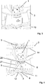
3 die Verfahrvorrichtung in der Standstellung, -
4 die Verfahrvorrichtung während eines Winkel-Einstellvorganges, -
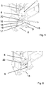
5 die Verfahrvorrichtung mit teilweise geöffneter Gehäusewand, und -
6 die Verfahrvorrichtung mit teilweise geöffneter Gehäusewand in einer Verfahrstellung zeigt.
-
1 a machine housing of a roll crusher, -
2 a traversing device in the displacement position, -
3 the traversing device in the standing position, -
4 the displacement device during an angle adjustment process, -
5 the traversing device with partially opened housing wall, and -
6 the positioning device with partially opened housing wall in a displacement position shows.
In
Die
In dem dargestellten Ausführungsbeispiel weist die Zerkleinerungsanlage das ausschnittsweise dargestellte Tragwerk
Das Tragwerk
In dem dargestellten Ausführungsbeispiel haben das Rad
Nach der Drehung werden die Winkelstellung des Stützelementes
BezugszeichenlisteLIST OF REFERENCE NUMBERS
- 11
- Verfahrvorrichtung einer ZerkleinerungsmaschineTraveling device of a crusher
- 22
- Maschinengehäusemachine housing
- 33
- Gehäusewandhousing wall
- 44
- HydlaulikzylinderHydlaulikzylinder
- 55
- Druckelementpressure element
- 66
- DruckelementeinführöffnungDruckelementeinführöffnung
- 77
- Schienerail
- 88th
- Schienenführungrail guide
- 99
- Verrieglungselementlocking element
- 1010
- TragwerkStructure
- 1111
- Drehscheibeturntable
- 1212
- Schienensegment auf DrehscheibeRail segment on turntable
- 1313
- Ausbuchtungbulge
- 1414
- Versteifungsrippenstiffening ribs
- 1515
- zylindermantelförmige Versteifungsrippecylinder jacket-shaped stiffening rib
- 1616
- Stützelementsupport element
- 1717
- Radwheel
- 1818
- quaderförmige Ausnehmungcuboid recess
- 1919
- zylinder- und quaderförmige Ausnehmungcylindrical and cuboid recess
- 2020
- Gewinderingthreaded ring
- 2121
- Schlüsselkey
Claims (10)
Priority Applications (10)
| Application Number | Priority Date | Filing Date | Title |
|---|---|---|---|
| DE102016221663.5A DE102016221663A1 (en) | 2016-11-04 | 2016-11-04 | Crushing plant with a crusher |
| CL2017002270A CL2017002270A1 (en) | 2016-11-04 | 2017-09-07 | Crushing plant in which the wall of the housing has at least one recess configured for the housing of the displacement device, so that the displacement device is integrated into the wall of the housing within its width, so that it is at less partially arranged in the recess. |
| EA201700423A EA032996B1 (en) | 2016-11-04 | 2017-09-20 | Comminuting plant with a comminuting machine |
| PE2017002094A PE20180886A1 (en) | 2016-11-04 | 2017-10-12 | CRUSHING PLANT WITH CRUSHING MACHINE |
| CA2982724A CA2982724C (en) | 2016-11-04 | 2017-10-17 | Comminuting plant with a comminuting machine |
| US15/786,613 US20180126388A1 (en) | 2016-11-04 | 2017-10-18 | Comminution Plant with a Comminution Machine |
| AU2017248526A AU2017248526B2 (en) | 2016-11-04 | 2017-10-20 | Comminuting plant with a comminuting machine |
| MX2017013541A MX2017013541A (en) | 2016-11-04 | 2017-10-20 | Comminution plant with a comminution machine. |
| EP17199538.4A EP3318331B1 (en) | 2016-11-04 | 2017-11-01 | Crushing system with a crushing machine |
| PL17199538T PL3318331T3 (en) | 2016-11-04 | 2017-11-01 | Crushing system with a crushing machine |
Applications Claiming Priority (1)
| Application Number | Priority Date | Filing Date | Title |
|---|---|---|---|
| DE102016221663.5A DE102016221663A1 (en) | 2016-11-04 | 2016-11-04 | Crushing plant with a crusher |
Publications (1)
| Publication Number | Publication Date |
|---|---|
| DE102016221663A1 true DE102016221663A1 (en) | 2018-05-09 |
Family
ID=60201894
Family Applications (1)
| Application Number | Title | Priority Date | Filing Date |
|---|---|---|---|
| DE102016221663.5A Withdrawn DE102016221663A1 (en) | 2016-11-04 | 2016-11-04 | Crushing plant with a crusher |
Country Status (10)
| Country | Link |
|---|---|
| US (1) | US20180126388A1 (en) |
| EP (1) | EP3318331B1 (en) |
| AU (1) | AU2017248526B2 (en) |
| CA (1) | CA2982724C (en) |
| CL (1) | CL2017002270A1 (en) |
| DE (1) | DE102016221663A1 (en) |
| EA (1) | EA032996B1 (en) |
| MX (1) | MX2017013541A (en) |
| PE (1) | PE20180886A1 (en) |
| PL (1) | PL3318331T3 (en) |
Families Citing this family (4)
| Publication number | Priority date | Publication date | Assignee | Title |
|---|---|---|---|---|
| EP3453460B1 (en) * | 2017-09-07 | 2023-07-26 | M&J Denmark A/S | A comminution apparatus and a method for performing service of such an apparatus |
| USD872141S1 (en) * | 2018-08-10 | 2020-01-07 | Superior Industries, Inc. | Jaw crusher forward wall |
| WO2020251950A1 (en) * | 2019-06-10 | 2020-12-17 | Ssi Shredding Systems, Inc. | Modular industrial reducing machine and method for disassembling an industrial reducing machine |
| CN114669362B (en) * | 2022-04-05 | 2023-09-01 | 武汉华材表面科技有限公司 | Roller sleeve of roller press with full-face column nails on roller surface and manufacturing method thereof |
Citations (1)
| Publication number | Priority date | Publication date | Assignee | Title |
|---|---|---|---|---|
| DE2905615B1 (en) * | 1979-02-14 | 1980-07-10 | Aulmann & Beckschulte | Sinter crusher |
Family Cites Families (8)
| Publication number | Priority date | Publication date | Assignee | Title |
|---|---|---|---|---|
| US2739830A (en) * | 1951-02-23 | 1956-03-27 | Dodge Mfg Corp | Shaft collars |
| GB948973A (en) * | 1961-10-31 | 1964-02-05 | Atomic Energy Authority Uk | Improvements in or relating to shielding for package irradiation plant |
| ITMI20032285A1 (en) * | 2003-11-24 | 2005-05-25 | Luigi Perego Srl | WHEEL FOR TROLLEYS |
| DE102007039766A1 (en) * | 2006-09-11 | 2008-03-27 | ThyssenKrupp Fördertechnik GmbH | Mobile crusher plant |
| DE102007031879B4 (en) * | 2007-07-09 | 2009-07-02 | Polysius Ag | Roller press with displaceable head pieces |
| CN103586106B (en) * | 2013-11-15 | 2015-11-11 | 河南省振源科技有限公司 | Carry the large-scale double-geared roller crusher of high-efficiency sieve fraction of feeding-distribution device |
| US9150393B2 (en) * | 2013-12-02 | 2015-10-06 | Chung-Yi Yang | Thin jack |
| CN104368412B (en) * | 2014-11-05 | 2016-08-24 | 重庆市金盾橡胶制品有限公司 | A kind of rubber rubber powder pulverizer being moved easily |
-
2016
- 2016-11-04 DE DE102016221663.5A patent/DE102016221663A1/en not_active Withdrawn
-
2017
- 2017-09-07 CL CL2017002270A patent/CL2017002270A1/en unknown
- 2017-09-20 EA EA201700423A patent/EA032996B1/en not_active IP Right Cessation
- 2017-10-12 PE PE2017002094A patent/PE20180886A1/en unknown
- 2017-10-17 CA CA2982724A patent/CA2982724C/en active Active
- 2017-10-18 US US15/786,613 patent/US20180126388A1/en not_active Abandoned
- 2017-10-20 AU AU2017248526A patent/AU2017248526B2/en active Active
- 2017-10-20 MX MX2017013541A patent/MX2017013541A/en unknown
- 2017-11-01 PL PL17199538T patent/PL3318331T3/en unknown
- 2017-11-01 EP EP17199538.4A patent/EP3318331B1/en active Active
Patent Citations (1)
| Publication number | Priority date | Publication date | Assignee | Title |
|---|---|---|---|---|
| DE2905615B1 (en) * | 1979-02-14 | 1980-07-10 | Aulmann & Beckschulte | Sinter crusher |
Also Published As
| Publication number | Publication date |
|---|---|
| CA2982724A1 (en) | 2018-05-04 |
| PL3318331T3 (en) | 2019-06-28 |
| PE20180886A1 (en) | 2018-05-24 |
| CA2982724C (en) | 2019-08-20 |
| AU2017248526B2 (en) | 2019-01-17 |
| US20180126388A1 (en) | 2018-05-10 |
| CL2017002270A1 (en) | 2018-03-09 |
| MX2017013541A (en) | 2018-09-28 |
| AU2017248526A1 (en) | 2018-05-24 |
| EP3318331B1 (en) | 2019-01-02 |
| EA201700423A1 (en) | 2018-05-31 |
| EA032996B1 (en) | 2019-08-30 |
| EP3318331A1 (en) | 2018-05-09 |
Similar Documents
| Publication | Publication Date | Title |
|---|---|---|
| EP3318331B1 (en) | Crushing system with a crushing machine | |
| EP0920555B1 (en) | Device for milling ground surfaces, specially roadways | |
| EP3313576B1 (en) | Material-bed roller mill | |
| EP1708815B1 (en) | One-sided double folding frame for roller presses | |
| EP2931430B1 (en) | Roller press | |
| EP2307144B1 (en) | Feed device with two rotary valves which are variable independently of each other | |
| DE102013010220A1 (en) | High pressure roller press with pendulum suspension | |
| EP1121982A1 (en) | Mobile crusher apparatus | |
| EP3027323B1 (en) | Closing system for ball mills and method of opening and closing of ball mills | |
| DE3110444C2 (en) | Mobile shredding plant | |
| EP3494259B1 (en) | Bridge prop for propping a bridge segment and method for operating bridge props | |
| EP1572386B1 (en) | Rolling mill comprising means for the change of rolls | |
| EP3206796B1 (en) | Roller press with widened frame head | |
| DE3212724C2 (en) | ||
| DE202022002968U1 (en) | Shredding machine | |
| DE3905682C2 (en) | ||
| WO2014202212A2 (en) | Roller mill for the comminution of brittle grinding stock | |
| EP0428905A2 (en) | Roller mill | |
| EP2764805B1 (en) | Optimised brewing unit housing | |
| EP2735370A1 (en) | Wearing part replacement apparatus | |
| DE202012012284U1 (en) | Strand guide for a continuous casting plant | |
| DE102013202071B4 (en) | Method and device for supporting and moving a semi-mobile crushing plant | |
| EP3932561A1 (en) | Mobile crushing plant and method for reducing the transport height of a mobile crushing plant | |
| DE102019204822A1 (en) | Shredding device with a protective cover | |
| WO2014041053A1 (en) | Roller press having a pulling device for simplified installation and removal of the rollers |
Legal Events
| Date | Code | Title | Description |
|---|---|---|---|
| R012 | Request for examination validly filed | ||
| R079 | Amendment of ipc main class |
Free format text: PREVIOUS MAIN CLASS: B02C0004280000 Ipc: B02C0023000000 |
|
| R120 | Application withdrawn or ip right abandoned |