DE102016202501A1 - Method for determining a calibration current pulse - Google Patents
Method for determining a calibration current pulse Download PDFInfo
- Publication number
- DE102016202501A1 DE102016202501A1 DE102016202501.5A DE102016202501A DE102016202501A1 DE 102016202501 A1 DE102016202501 A1 DE 102016202501A1 DE 102016202501 A DE102016202501 A DE 102016202501A DE 102016202501 A1 DE102016202501 A1 DE 102016202501A1
- Authority
- DE
- Germany
- Prior art keywords
- measuring resistor
- connection point
- resistor
- measuring
- messwiderstand
- Prior art date
- Legal status (The legal status is an assumption and is not a legal conclusion. Google has not performed a legal analysis and makes no representation as to the accuracy of the status listed.)
- Granted
Links
- 238000000034 method Methods 0.000 title claims abstract description 57
- 238000005259 measurement Methods 0.000 claims description 19
- 238000004364 calculation method Methods 0.000 abstract description 6
- 239000000463 material Substances 0.000 description 4
- 230000001419 dependent effect Effects 0.000 description 3
- 238000001514 detection method Methods 0.000 description 3
- 230000004044 response Effects 0.000 description 3
- 238000004088 simulation Methods 0.000 description 3
- 230000032683 aging Effects 0.000 description 2
- 238000013459 approach Methods 0.000 description 2
- 238000004422 calculation algorithm Methods 0.000 description 2
- 230000000875 corresponding effect Effects 0.000 description 2
- 238000011156 evaluation Methods 0.000 description 2
- 238000000605 extraction Methods 0.000 description 2
- 238000003860 storage Methods 0.000 description 2
- 229910000896 Manganin Inorganic materials 0.000 description 1
- 229910000914 Mn alloy Inorganic materials 0.000 description 1
- 229910045601 alloy Inorganic materials 0.000 description 1
- 239000000956 alloy Substances 0.000 description 1
- 230000006399 behavior Effects 0.000 description 1
- 238000010276 construction Methods 0.000 description 1
- UTICYDQJEHVLJZ-UHFFFAOYSA-N copper manganese nickel Chemical compound [Mn].[Ni].[Cu] UTICYDQJEHVLJZ-UHFFFAOYSA-N 0.000 description 1
- 230000002596 correlated effect Effects 0.000 description 1
- 238000011161 development Methods 0.000 description 1
- 230000018109 developmental process Effects 0.000 description 1
- 238000010586 diagram Methods 0.000 description 1
- 238000009826 distribution Methods 0.000 description 1
- 230000005611 electricity Effects 0.000 description 1
- 238000005265 energy consumption Methods 0.000 description 1
- 238000005516 engineering process Methods 0.000 description 1
- 238000004519 manufacturing process Methods 0.000 description 1
- 230000008092 positive effect Effects 0.000 description 1
- 238000011084 recovery Methods 0.000 description 1
- 238000001228 spectrum Methods 0.000 description 1
- 239000007858 starting material Substances 0.000 description 1
- 230000035882 stress Effects 0.000 description 1
- 230000001629 suppression Effects 0.000 description 1
- 230000036962 time dependent Effects 0.000 description 1
- 230000007704 transition Effects 0.000 description 1
Images
Classifications
-
- G—PHYSICS
- G01—MEASURING; TESTING
- G01R—MEASURING ELECTRIC VARIABLES; MEASURING MAGNETIC VARIABLES
- G01R35/00—Testing or calibrating of apparatus covered by the other groups of this subclass
-
- G—PHYSICS
- G01—MEASURING; TESTING
- G01R—MEASURING ELECTRIC VARIABLES; MEASURING MAGNETIC VARIABLES
- G01R1/00—Details of instruments or arrangements of the types included in groups G01R5/00 - G01R13/00 and G01R31/00
- G01R1/20—Modifications of basic electric elements for use in electric measuring instruments; Structural combinations of such elements with such instruments
- G01R1/203—Resistors used for electric measuring, e.g. decade resistors standards, resistors for comparators, series resistors, shunts
-
- G—PHYSICS
- G01—MEASURING; TESTING
- G01R—MEASURING ELECTRIC VARIABLES; MEASURING MAGNETIC VARIABLES
- G01R19/00—Arrangements for measuring currents or voltages or for indicating presence or sign thereof
- G01R19/0092—Arrangements for measuring currents or voltages or for indicating presence or sign thereof measuring current only
-
- G—PHYSICS
- G01—MEASURING; TESTING
- G01R—MEASURING ELECTRIC VARIABLES; MEASURING MAGNETIC VARIABLES
- G01R19/00—Arrangements for measuring currents or voltages or for indicating presence or sign thereof
- G01R19/10—Measuring sum, difference or ratio
Landscapes
- Physics & Mathematics (AREA)
- General Physics & Mathematics (AREA)
- Measurement Of Current Or Voltage (AREA)
Abstract
Die Erfindung betrifft ein Verfahren zum Bestimmen eines Kalibrierstrompulses bei Überlagerung durch einen Nutzstrompuls, wobei der Kalibrierstrompuls rechnerisch nach Messung über mehrere Messwiderstände einer Messwiderstandsgruppe ermittelt wird.The invention relates to a method for determining a Kalibrierstrompulses when superimposed by a Nutzstrompuls, the Kalibrierstrompuls is determined by calculation over several measuring resistances of a measuring resistor group.
Description
Die Erfindung betrifft ein Verfahren zum Bestimmen eines Kalibrierstrompulses.The invention relates to a method for determining a calibration current pulse.
In Kraftfahrzeugen wird zunehmend eine Batteriezustandserkennung durchgeführt, um die Leistungsfähigkeit der Batterie zuverlässig zu berechnen. Für die Erfassung der Batteriemessgrößen wird dabei typischerweise ein sogenannter Intelligenter Batteriesensor (IBS) eingesetzt.In automobiles, a battery state detection is increasingly performed to reliably calculate the performance of the battery. A so-called Intelligent Battery Sensor (IBS) is typically used for the detection of the battery measured variables.
Eine kontinuierliche Messung des Batteriezustands ist dabei vorteilhaft, um die Leistungsbilanz des Kraftfahrzeuges zu optimieren und somit einen erheblichen Beitrag zur Verbrauchsminderung und zur CO2-Einsparung zu leisten. Zu der kurzeitigen Leistungsabgabe bei Motorstarts kommen in modernen Fahrzeugen Innovationen wie z.B. Start-Stopp-Betrieb und Rekuperation hinzu, welche zu einem erhöhten Energieumsatz führen und die Batterie zusätzlich zu den bereits bekannten Leistungsabgaben beanspruchen.A continuous measurement of the battery state is advantageous in order to optimize the power balance of the motor vehicle and thus make a significant contribution to reducing consumption and CO 2 savings. In addition to the short-term power output during engine starts, innovations such as start-stop operation and recuperation are added in modern vehicles, which lead to increased energy consumption and stress the battery in addition to the already known power outputs.
Eine Erfassung der Batteriemessgrößen Strom, Spannung und Temperatur soll typischerweise sehr genau, dynamisch und zeitsynchron sein, um den Batteriezustand, die Leistungsfähigkeit der Batterie und deren Alterungsgrad ermitteln zu können, beispielsweise mittels eines Algorithmus.A detection of the battery measured quantities current, voltage and temperature should typically be very accurate, dynamic and time-synchronized in order to be able to determine the battery condition, the performance of the battery and its degree of aging, for example by means of an algorithm.
Die Messung der Batteriemessgröße Strom wird heute in der Regel mit Hilfe eines hochwertigen und präzisen Messwiderstands, auch als Messshunt bezeichnet, durchgeführt, welcher typischerweise einen Drift seines Widerstandswerts von weniger als 1 % vom Messwert über seine Lebensdauer von beispielsweise 15 Jahren aufweist. Dieser Messwiderstand ist jedoch mit einer hohen Genauigkeit und geringem Temperaturgang in der Regel auch sehr kostenintensiv. Beispielhaft kann hierfür eine Kupfer-Nickel-Mangan-Legierung, insbesondere eine als Manganin bekannte Legierung, verwendet werden.The measurement of the battery measured variable current today is usually carried out with the aid of a high-quality and precise measuring resistor, also called a measuring shunt, which typically has a drift of its resistance value of less than 1% of the measured value over its service life of, for example, 15 years. However, this measuring resistor is usually very costly with high accuracy and low temperature response. By way of example, a copper-nickel-manganese alloy, in particular an alloy known as manganin, can be used for this purpose.
Um zukünftig kostengünstigere Widerstandsmaterialien bzw. Messwiderstände mit einer höheren Ungenauigkeit beim Widerstandswert und Temperaturgang verwenden zu können, besteht die Möglichkeit, eine kontinuierliche Kalibration des Messsytem im Betrieb durchzuführen, um die Ungenauigkeiten zu kompensieren. Eine solche Kalibration soll vorteilhaft kontinuierlich während der gesamten Lebensdauer des Batteriesensors im eingebauten Zustand im Fahrzeug erfolgen.In order to be able to use more cost-effective resistance materials or measuring resistors with a higher inaccuracy in the resistance value and temperature response in the future, it is possible to carry out a continuous calibration of the measuring system during operation in order to compensate for the inaccuracies. Such a calibration should advantageously be carried out continuously during the entire service life of the battery sensor when installed in the vehicle.
Dies kann beispielsweise mit einem kontinuierlichen wiederkehrenden Kalibrationsstrompuls bzw. Kalibrierstrompuls erfolgen. Dieser Kalibrierstrompuls kann auf der Batteriesensorplatine generiert werden. Er erzeugt beispielsweise an einem Referenzwiderstand wie auch an dem Messwiderstand über alle Temperatur- und Laststrombereiche Spannungsabfälle, die dann kontinuierlich gemessen und ins Verhältnis gesetzt werden können. Somit ist ein kontinuierlicher Abgleich mit einem Referenzwiderstand möglich.This can be done, for example, with a continuous recurring calibration current pulse or calibration current pulse. This calibration current pulse can be generated on the battery sensor board. For example, it generates voltage drops across a reference resistor as well as the measuring resistor across all temperature and load current ranges, which can then be measured and correlated continuously. Thus, a continuous comparison with a reference resistor is possible.
Als problematisch hat sich bei kontinuierlichen Kalibrationsverfahren erwiesen, dass sich dabei der Kalibrationsstrompuls und der Laststrom addieren und nur wieder schwer voneinander trennen lassen, was zu großen Problemen bei der Auswertung der Messdaten führt. It has proven to be problematic in continuous calibration methods that the calibration current pulse and the load current are added together and can only be separated from one another again with difficulty, which leads to great problems in the evaluation of the measured data.
Es ist deshalb eine Aufgabe der Erfindung, ein Verfahren zum Bestimmen eines Kalibrierstrompulses bereitzustellen, welches diesbezüglich verbessert ist.It is therefore an object of the invention to provide a method for determining a calibration current pulse which is improved in this regard.
Dies wird erfindungsgemäß durch ein Verfahren nach Anspruch 1 erreicht. Vorteilhafte Ausgestaltungen können beispielsweise den Unteransprüchen entnommen werden. Der Inhalt der Ansprüche wird durch ausdrückliche Inbezugnahme zum Inhalt der Beschreibung gemacht.This is achieved according to the invention by a method according to
Die Erfindung betrifft ein Verfahren zum Bestimmen eines Kalibrierstrompulses an einer Messwiderstandsgruppe. Die Messwiderstandsgruppe weist eine Anzahl von Messwiderständen auf, welche an jeweiligen Verbindungspunkten miteinander oder mit weiteren Komponenten verbunden sind.The invention relates to a method for determining a calibration current pulse on a measuring resistor group. The measuring resistor group has a number of measuring resistors, which are connected at respective connection points with each other or with other components.
Durch den Übergang von einem Messwiderstand zu einer Messwiderstandsgruppe wird eine besondere ´Vorgehensweise ermöglicht, welche Teil des erfindungsgemäßen Verfahrens ist.The transition from a measuring resistor to a measuring resistor group enables a special procedure, which is part of the method according to the invention.
Es sei verstanden, dass die Verbindungspunkte vielfältig ausgestaltet sein können, beispielsweise als elektrische Kontakte zwischen physisch abgrenzbaren Widerständen. Es kann sich jedoch auch lediglich um bestimmte Punkte oder Orte auf Widerstandsmaterialien handeln, welche Teilbereiche dieser Widerstandsmaterialien voneinander abgrenzen.It should be understood that the connection points can be configured in many ways, for example as electrical contacts between physically delimitable resistors. However, it may also be merely specific points or locations on resistance materials which delimit parts of these resistance materials from each other.
Das Verfahren weist folgende Schritte auf:
- – Durchleiten eines Laststroms durch einen ersten Messwiderstand der Messwiderstandsgruppe und durch einen zweiten Messwiderstand der Messwiderstandsgruppe, gleichzeitig
- – Durchleiten eines Kalibrierstroms durch zumindest den ersten Messwiderstand, gleichzeitig
- – Messen eines ersten Spannungspulses zwischen einem ersten Verbindungspunkt und einem zweiten Verbindungspunkt, wobei der erste Verbindungspunkt unmittelbar mit dem ersten Messwiderstand verbunden ist, und
- – Berechnen des Kalibrierstrompulses basierend zumindest auf dem ersten Spannungspuls.
- Passing a load current through a first measuring resistor of the measuring resistor group and through a second measuring resistor of the measuring resistor group, simultaneously
- - Passing a calibration current through at least the first measuring resistor, simultaneously
- - Measuring a first voltage pulse between a first connection point and a second connection point, wherein the first connection point is directly connected to the first sense resistor, and
- - Calculating the Kalibrierstrompulses based at least on the first voltage pulse.
Durch die besondere Vorgehensweise ist es möglich, anhand des ersten Spannungspulses einen Rückschluss auf den Kalibrierstrom zu erhalten, welcher sich vom Laststrom trennen lässt. Mögliche konkrete Ausgestaltungen werden weiter unten in der Anmeldung beschrieben. Due to the special procedure, it is possible to obtain a conclusion about the calibration current based on the first voltage pulse, which can be separated from the load current. Possible specific embodiments are described below in the application.
Bei dem Laststrom handelt es sich insbesondere um einen Strom, welcher von der Batterie zum Chassis oder umgekehrt fließt, beispielsweise weil Verbraucher im Fahrzeug einen entsprechenden Strombedarf haben. Hierbei kann es sich beispielsweise um Anlasser oder Scheinwerfer handeln.In particular, the load current is a current which flows from the battery to the chassis or vice versa, for example because consumers in the vehicle have a corresponding power requirement. This may be, for example, starter or headlights.
Bei einer Batterie kann es sich beispielsweise um eine typische Autobatterie handeln, welche insbesondere als Akkumulator ausgebildet sein kann. Auch für andere Batterien oder Akkumulatoren bzw. allgemein Stromspeicher oder Stromerzeuger ist das Verfahren jedoch entsprechend anwendbar.A battery may be, for example, a typical car battery, which may be designed in particular as an accumulator. However, the method is also applicable to other batteries or accumulators or general electricity storage or power generator.
Gemäß einer Ausführung ist vorgesehen, dass der zweite Verbindungspunkt unmittelbar mit dem ersten Messwiderstand verbunden ist, so dass der erste Spannungspuls genau über dem ersten Messwiderstand gemessen wird.According to one embodiment, it is provided that the second connection point is connected directly to the first measuring resistor, so that the first voltage pulse is measured exactly above the first measuring resistor.
Das Verfahren weist gemäß einer Ausführung ferner gleichzeitig zum Schritt des Messens des ersten Spannungspulses folgenden Schritt auf:
- – Messen eines zweiten Spannungspulses zwischen einem dritten Verbindungspunkt und einem vierten Verbindungspunkt, wobei der dritte Verbindungspunkt unmittelbar mit dem zweiten Messwiderstand verbunden ist, und
- – wobei der Kalibrierstrompuls auch basierend auf dem zweiten Spannungspuls berechnet wird.
- - Measuring a second voltage pulse between a third connection point and a fourth connection point, wherein the third connection point is directly connected to the second measuring resistor, and
- - The calibration current pulse is also calculated based on the second voltage pulse.
Durch das Messen des zweiten Spannungspulses können unterschiedliche Lösungen verwendet werden, um den Kalibrierstrompuls von der Überlagerung mit dem Laststrom zu extrahieren. Beispielhafte Vorgehensweisen werden nachfolgend beschrieben.By measuring the second voltage pulse, different solutions can be used to extract the calibration current pulse from the superposition with the load current. Exemplary procedures will be described below.
Gemäß einer Ausführung ist der vierte Verbindungspunkt unmittelbar mit dem zweiten Messwiderstand verbunden, so dass der zweite Spannungspuls genau über dem zweiten Messwiderstand gemessen wird.According to one embodiment, the fourth connection point is directly connected to the second measurement resistor, so that the second voltage pulse is measured exactly above the second measurement resistor.
Gemäß einer Ausführung ist der zweite Verbindungspunkt unmittelbar mit dem zweiten Messwiderstand verbunden.According to one embodiment, the second connection point is directly connected to the second measuring resistor.
Vorteilhaft wird der Kalibrierstrompuls auch basierend auf einem Widerstandswert des ersten Messwiderstands und/oder einem Widerstandswert des zweiten Messwiderstands und/oder jeweiligen Widerstandswerten weiterer Messwiderstände der Messwiderstandsgruppe berechnet. Dabei kann auf alle Kombinationen der genannten Werte zurückgegriffen werden, also beispielsweise mit einem dieser Werte, mit zwei beliebigen dieser Werte oder mit drei dieser Werte. Insbesondere können Verhältnisse von Widerständen berücksichtigt werden, wie die weiter unten näher ausgeführt wird.Advantageously, the calibration current pulse is also calculated based on a resistance value of the first measuring resistor and / or a resistance value of the second measuring resistor and / or respective resistance values of further measuring resistors of the measuring resistor group. It is possible to fall back on all combinations of the named values, that is, for example, with one of these values, with any two of these values, or with three of these values. In particular, ratios of resistances can be taken into account, as will be explained in more detail below.
Gemäß einer bevorzugten Ausführung wird der Kalibrierstrom seriell zum ersten Messwiderstand durch einen Referenzwiderstand geleitet und ein Spannungsabfall wird über dem Referenzwiderstand gemessen. Dies ermöglicht eine genaue Bestimmung der Stromstärke des Kalibrierstroms.According to a preferred embodiment, the calibration current is conducted serially to the first sense resistor through a reference resistor, and a voltage drop is measured across the reference resistance. This allows accurate determination of the current strength of the calibration current.
Gemäß einer Ausführung wird der Laststrom in einen ersten Pfad und einen dazu parallelen zweiten Pfad aufgeteilt. Vorzugsweise wird er zu gleichen Teilen aufgeteilt. Dies entspricht einer möglichen Vorgehensweise, um Laststrom und Kalibrierstrom voneinander zu trennen.According to one embodiment, the load current is split into a first path and a second path parallel thereto. Preferably, it is divided equally. This corresponds to a possible procedure for separating the load current from the calibration current.
Nachfolgend werden bestimmte spezifische Ausführungen beschrieben, welche die Erfinder als vorteilhafte, jedoch nicht als einzige Ausführungen zur Durchführung des Verfahrens erkannt haben. Es sei erwähnt, dass die Spannungspulse dabei typischerweise entsprechend der obigen Angaben bezüglich der Verbindungspunkte gemessen werden.Hereinafter, certain specific embodiments will be described, which the inventors have recognized as advantageous, but not as sole embodiments for carrying out the method. It should be noted that the voltage pulses are typically measured in accordance with the above information regarding the connection points.
Gemäß einer Ausführung ist vorgesehen,
- – dass der erste Pfad den ersten Messwiderstand und seriell dazu einen dritten Messwiderstand aufweist,
- – dass der erste Messwiderstand und der dritte Messwiderstand am ersten Verbindungspunkt miteinander verbunden sind,
- – dass der zweite Pfad den zweiten Messwiderstand aufweist,
- – dass der dritte Messwiderstand und der zweite Messwiderstand am dritten Verbindungspunkt miteinander verbunden sind, und
- – dass der erste Messwiderstand und der zweite Messwiderstand am zweiten Verbindungspunkt miteinander verbunden sind, welcher gleichzeitig den vierten Verbindungspunkt bildet.
- That the first path has the first measuring resistor and, in series, a third measuring resistor,
- - That the first measuring resistor and the third measuring resistor are connected to each other at the first connection point,
- That the second path has the second measuring resistor,
- - That the third measuring resistor and the second measuring resistor are connected to each other at the third connection point, and
- - That the first measuring resistor and the second measuring resistor are connected to each other at the second connection point, which simultaneously forms the fourth connection point.
Gemäß einer Ausführung ist vorgesehen,
- – dass der erste Pfad den ersten Messwiderstand, seriell dazu einen dritten Messwiderstand und seriell dazu einen vierten Messwiderstand aufweist,
- – dass der erste Messwiderstand und der dritte Messwidersand am ersten Verbindungspunkt miteinander verbunden sind,
- – dass der erste Messwiderstand und der vierte Messwiderstand am zweiten Verbindungspunkt miteinander verbunden sind,
- dass der zweite Pfad den zweiten Messwiderstand aufweist,
- – dass der dritte Messwiderstand und der zweite Messwiderstand am dritten Verbindungspunkt miteinander verbunden sind, und
- – dass der vierte Messwiderstand und der zweite Messwiderstand am vierten Verbindungspunkt miteinander verbunden sind.
- The first path has the first measuring resistor, a third measuring resistor in series therewith, and a fourth measuring resistor in series therewith,
- That the first measuring resistor and the third measuring resistor are connected to one another at the first connection point,
- - That the first measuring resistor and the fourth measuring resistor are connected to each other at the second connection point,
- that the second path has the second measuring resistor,
- - That the third measuring resistor and the second measuring resistor are connected to each other at the third connection point, and
- - That the fourth measuring resistor and the second measuring resistor are connected to each other at the fourth connection point.
Gemäß einer Ausführung ist vorgesehen,
- – dass der erste Pfad den ersten Messwiderstand und seriell dazu einen dritten Messwiderstand aufweist,
- – dass der erste Messwiderstand und der dritte Messwiderstand am ersten Verbindungspunkt miteinander verbunden sind,
- – dass der zweite Pfad den zweiten Messwiderstand und seriell dazu einen vierten Messwiderstand aufweist,
- – dass der zweite Messwiderstand und der vierte Messwiderstand am dritten Verbindungspunkt miteinander verbunden sind,
- – dass der dritte Messwiderstand und der vierte Messwiderstand an einem fünften Verbindungspunkt miteinander verbunden sind, und
- – dass der erste Messwiderstand und der zweite Messwiderstand am zweiten Verbindungspunkt miteinander verbunden sind, welcher gleichzeitig den vierten Verbindungspunkt bildet.
- That the first path has the first measuring resistor and, in series, a third measuring resistor,
- - That the first measuring resistor and the third measuring resistor are connected to each other at the first connection point,
- - That the second path has the second measuring resistor and serially to a fourth measuring resistor,
- - That the second measuring resistor and the fourth measuring resistor are connected to each other at the third connection point,
- - That the third measuring resistor and the fourth measuring resistor are connected to one another at a fifth connection point, and
- - That the first measuring resistor and the second measuring resistor are connected to each other at the second connection point, which simultaneously forms the fourth connection point.
Gemäß einer Ausführung ist vorgesehen,
- – dass der erste Pfad den ersten Messwiderstand und seriell dazu einen dritten Messwiderstand aufweist,
- – dass der zweite Pfad den zweiten Messwiderstand und seriell dazu einen vierten Messwiderstand aufweist,
- – dass der erste Messwiderstand und der dritte Messwiderstand am ersten Verbindungspunkt miteinander verbunden sind,
- – dass der zweite Messwiderstand und der vierte Messwiderstand am zweiten Verbindungspunkt miteinander verbunden sind,
- – dass der dritte Messwiderstand und der vierte Messwiderstand an einem weiteren Verbindungspunkt miteinander verbunden sind, und
- – dass der erste Messwidersand und der zweite Messwiderstand an noch einem weiteren Verbindungspunkt miteinander verbunden sind.
- That the first path has the first measuring resistor and, in series, a third measuring resistor,
- - That the second path has the second measuring resistor and serially to a fourth measuring resistor,
- - That the first measuring resistor and the third measuring resistor are connected to each other at the first connection point,
- - That the second measuring resistor and the fourth measuring resistor are connected to each other at the second connection point,
- - That the third measuring resistor and the fourth measuring resistor are connected to each other at a further connection point, and
- - That the first measuring resistance and the second measuring resistor are connected to each other at yet another connection point.
Gemäß einer Ausführung ist vorgesehen,
- – dass der erste Messwiderstand und der zweite Messwiderstand seriell zueinander geschaltet sind,
- – dass der erste Messwiderstand und der zweite Messeiderstand am ersten Verbindungspunkt miteinander verbunden sind, welcher gleichzeitig den vierten Verbindungspunkt bildet,
- – dass der zweite Verbindungspunkt ein dem ersten Verbindungspunkt gegenüberliegender Pol des ersten Messwiderstands ist, und
- – dass der dritte Verbindungspunkt ein dem vierten Verbindungspunkt gegenüberliegender Pol des zweiten Messwiderstands ist.
- - That the first measuring resistor and the second measuring resistor are connected in series with each other,
- That the first measuring resistor and the second measuring resistor are connected to one another at the first connecting point, which simultaneously forms the fourth connecting point,
- - That the second connection point is a first connection point opposite pole of the first sense resistor, and
- - That the third connection point is a fourth connection point opposite pole of the second measuring resistor.
Alle diese Ausführungen ermöglichen eine vorteilhafte Bestimmung des Kalibrierstrompulses. Auf Details wird weiter unten mit Bezug auf die beigefügte Zeichnung näher eingegangen werden.All of these embodiments allow an advantageous determination of the Kalibrierstrompulses. Details will be discussed below with reference to the accompanying drawings.
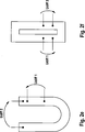
Gemäß einer bevorzugten Ausführung wird der Kalibrierstrom am ersten Verbindungspunkt in die Messwiderstandsgruppe eingeleitet. Dies kann insbesondere vorteilhaft mit den oben beschriebenen Ausführungen kombiniert werden. According to a preferred embodiment, the calibration current is introduced into the measuring resistor group at the first connection point. This can be particularly advantageously combined with the embodiments described above.
Gemäß einer Weiterbildung sind die Messwiderstände der Messwiderstandsgruppe als Teilbereiche eines flächigen Widerstands ausgeführt. Dies erlaubt eine einfache Herstellung der Widerstände. Beispielhafte Ausführungen sind weiter unten mit Bezug auf die beigefügte Zeichnung beschrieben. Es sei jedoch verstanden, dass auch beliebige andere Ausführungen von Widerständen in Betracht kommen, beispielsweise diskrete Widerstände.According to a development, the measuring resistors of the measuring resistor group are designed as subregions of a planar resistor. This allows easy production of the resistors. Exemplary embodiments are described below with reference to the accompanying drawings. It should be understood, however, that any other embodiments of resistors come into consideration, such as discrete resistors.
Die Erfindung betrifft des Weiteren einen Batteriesensor, welcher dazu konfiguriert ist, ein erfindungsgemäßes Verfahren auszuführen. Insbesondere kann der Batteriesensor Prozessormittel und Speichermittel aufweisen, wobei die Speichermittel Programmcode enthalten, bei dessen Ausführung die Prozessormittel ein erfindungsgemäßes Verfahren ausführen bzw. sich entsprechend verhalten. Außerdem kann der Batteriesensor eine Messwiderstandsbaugruppe aufweisen, welche wie mit Bezug auf das Verfahren beschrieben ausgeführt ist. Alle mit Bezug auf das Verfahren beschriebenen Ausführungen gelten entsprechend als mögliche vorrichtungsgemäße Ausführungen eines Batteriesensors. Hinsichtlich des Verfahrens kann auf alle beschriebenen Ausführungen und Varianten zurückgegriffen werden.The invention further relates to a battery sensor which is configured to carry out a method according to the invention. In particular, the battery sensor may comprise processor means and memory means, wherein the memory means comprise program code, in the execution of which the processor means execute a method according to the invention or behave accordingly. Additionally, the battery sensor may include a sensing resistor assembly configured as described with respect to the method. All embodiments described with reference to the method apply accordingly as possible device embodiments of a battery sensor. With regard to the method can be used on all described versions and variants.
Die Erfindung betrifft des Weiteren ein nichtflüchtiges computerlesbares Speichermedium, welches Programmcode enthält, bei dessen Ausführung ein Prozessor ein erfindungsgemäßes Verfahren ausführt. Hinsichtlich des Verfahrens kann auf alle beschriebenen Ausführungen und Varianten zurückgegriffen werden.The invention further relates to a non-transitory computer-readable storage medium containing program code, in the execution of which a processor executes a method according to the invention. With regard to the method can be used on all described versions and variants.
Allgemein gesagt ist es eine mögliche Grundidee der kontinuierlichen Kalibration, im eingebauten Zustand eines Sensors im Fahrzeug einen Kalibrationsstrom bzw. Kalibrierstrom zu erzeugen, der dann so geleitet wird, dass dieser einen Spannungsabfall an einem hochgenauen Vorwiderstand bzw. Referenzshunt wie auch am Messwiderstand bzw. Messshunt generiert. Dieser Spannungsabfall kann so kontinuierlich differenziell gemessen und die beiden Spannungen können ins Verhältnis gesetzt werden. Generally speaking, it is a possible basic idea of the continuous calibration, in the installed state of a sensor in the vehicle to generate a calibration current or calibration current, which is then directed so that this voltage drop at a high-precision resistor or reference shunt as well as the measuring resistor or Measurement shunt generated. This voltage drop can thus be continuously differentially measured and the two voltages can be set in proportion.
Wenn dies bei allen bekannten Lastfällen und Temperaturbereichen geschieht, können so die schlechteren spezifischen Eigenschaften des manganinlosen Messshuntmaterials kompensiert werden.If this happens for all known load cases and temperature ranges, then the poorer specific properties of the manganese-free measuring shunt material can be compensated.
Ausgehend davon soll der Referenzwiderstand nur minimales Alterungsverhalten und Temperaturgang aufweisen. Dies wird begünstigt, da dieser nur gering thermisch belastet wird und nur kleine Ströme fließen.Based on this, the reference resistance should have only minimal aging behavior and temperature response. This is favored because it is only slightly thermally loaded and only small currents flow.
Die Problematik und Schwierigkeit bei dieser Methode der kontinuierlichen Kalibration mittels Kalibrierstrom über einen Referenzwiderstand besteht aber darin, dass über den zu kalibrierenden Messshunt sowohl der Kalibrierstrom wie auch der Laststrom fließt. Diese beiden Ströme addieren sich und es entsteht ein Mischstrom. Der so entstandene Mischstrom beinhaltet Anteile von beiden Signalen, die nur schwer wieder voneinander zu trennen sind.The problem and difficulty with this method of continuous calibration by means of calibration current via a reference resistor, however, is that both the calibration current and the load current flow via the measuring shunt to be calibrated. These two streams add up and a mixed stream is created. The resulting mixed stream contains portions of both signals that are difficult to separate from each other.
Hier setzt die Erfindung an. Der Laststrom wird zunächst über dem Messwiderstand aufgeteilt und der Kalibrierstrom wird in den Messshunt derart eingespeist, dass dieser in unterschiedlicher Größe über den aufgeteilten Messwiderstand fließt. Durch eine einfache Subtraktion der Teillastströme kann beispielsweise der Kalibrierstrompuls wieder vom Laststrom extrahiert werden.This is where the invention starts. The load current is first divided over the measuring resistor and the calibration current is fed into the measuring shunt in such a way that it flows in different sizes over the divided measuring resistor. By a simple subtraction of the partial load currents, for example, the calibration current pulse can again be extracted from the load current.
Diese Verfahren stellt eine einfache und kostengünstige Methode dar, um das Kalibrierstromsignal vom Laststrom zu trennen. Weiter unten ist ein Beispiel dieser Methode durchgerechnet und zugehörige Simulationsergebnisse werden dargestellt.This method provides a simple and inexpensive way to separate the calibration current signal from the load current. Below, an example of this method is calculated and associated simulation results are displayed.
Das erfindungsgemäße Verfahren kann es beispielsweise erlauben, den erzeugten Kalibrierstrom vom Laststrom so zu trennen, dass das eigentliche Kalibrierstromsignal nahezu ohne Überlagerungen für die weitere Berechnung herangezogen werden kann. Zudem stellt es eine einfache, schnelle und kostengünstige Lösung dar, die relevanten Spannungsabfälle aus dem Mischstrom zu extrahieren.The method according to the invention may, for example, allow the generated calibration current to be separated from the load current in such a way that the actual calibration current signal can be used for the further calculation with almost no superpositions. It also provides a simple, fast and cost effective solution to extract the relevant voltage drops from the mixed stream.
Das Verfahren dieser Signalextraktion beruht beispielsweise zumindest in manchen Ausführungen auf der Methode der parallelen Messung am Messshunt, bei gleichzeitig anliegenden identischen Laststromsignalen. Der Trick kann beispielsweise sein, dass sich der Laststrom zu gleichen Teilen und der Kalibrierstrom ungleich über die Teilwiderstände verteilt. Subtrahiert man die Teillastströme, so bleibt ein Teil des Kalibrierstrompulses übrig.The method of this signal extraction is based, for example, at least in some embodiments, on the method of parallel measurement at the measuring shunt, with simultaneous identical load current signals. The trick may be, for example, that the load current is distributed in equal parts and the calibration current is distributed unevenly over the partial resistors. Subtracting the partial load currents, a part of the calibration current pulse remains.
Im Detail kann beispielsweise das kleinere Widerstandselement mit einem großen Anteil des Kalibrierstrompulses plus Laststrom durchflossen werden und das größere Widerstandselement kann mit einem im Verhältnis kleineren Anteil des Kalibrierstrompulses plus gleichem Anteil an Laststrom durchflossen werden.In detail, for example, the smaller resistance element can be traversed by a large proportion of the calibration current pulse plus load current, and the larger resistance element can be traversed by a smaller proportion of the calibration current pulse plus an equal proportion of load current.
Weitere Merkmale und Vorteile wird der Fachmann den nachfolgend mit Bezug auf die beigefügte Zeichnung beschriebenen Ausführungsbeispielen entnehmen. Dabei zeigen:Further features and advantages will be apparent to those skilled in the embodiments described below with reference to the accompanying drawings. Showing:
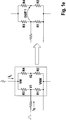
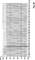
Die
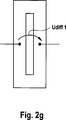
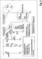
Die Messwiderstände sind an jeweiligen Verbindungspunkten untereinander und mit externen Komponenten verbunden. Die Verbindungspunkte sind mit den Bezugszeichen V1 für einen ersten Verbindungspunkt, V2 für einen zweiten Verbindungspunkt, V3 für einen dritten Verbindungspunkt, V4 für einen vierten Verbindungspunkt, V5 für einen fünften Verbindungspunkt, VW für einen weiteren Verbindungspunkt und VNW für einen noch weiteren Verbindungspunkt bezeichnet. The measuring resistors are connected at respective connection points with each other and with external components. The connection points are designated by the reference symbols V1 for a first connection point, V2 for a second connection point, V3 for a third connection point, V4 for a fourth connection point, V5 for a fifth connection point, VW for a further connection point and VNW for yet another connection point.
In die Messwiderstandsgruppe werden jeweils ein Laststrom IL und ein Referenzstrom IR eingeleitet, welche jeweils mit Pfeilen im jeweils linken Teil der Figuren eingezeichnet sind. Wie gezeigt wird der Referenzstrom IR gepulst angelegt, während der Laststrom IL als veränderlicher Strom gezeigt ist, da dieser vom aktuellen Strombedarf von Verbrauchern, beispielsweise in einem Fahrzeug, abhängt.In the measuring resistance group, a load current I L and a reference current I R are respectively initiated, which are each drawn with arrows in the left part of each of the figures. As shown, the reference current I R is applied pulsed, while the load current I L is shown as a variable current, since this depends on the current power consumption of consumers, for example in a vehicle.
In den jeweils rechten Teilen der Figuren sind jeweils auch die Bereiche gezeigt, über welche der erste Spannungspuls (Udiff1) und der zweite Spannungspuls (Udiff2) gemessen werden.In each case the right-hand parts of the figures also show the regions over which the first voltage pulse (Udiff1) and the second voltage pulse (Udiff2) are measured.
Bei dem Ausführungsbeispiel von
Dieses Verfahren kann in verschiedenen Widerstandsnetzwerken umgesetzt, gemessen und verrechnet werden. Darüber hinaus ist diese Methode unabhängig davon, wie der Kalibrierstrompuls erzeugt wird und auch unabhängig von der Art des Laststromes, da der Laststrom in den Messwiderständen nahezu identisch anliegt.This method can be implemented, measured and calculated in various resistor networks. In addition, this method is independent of how the calibration current pulse is generated and also regardless of the type of load current, since the load current in the measuring resistors is almost identical.
Nachfolgend werden die einzelnen Ausführungsbeispiele der
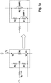
Gemäß dem Ausführungsbeispiel von
- – dass der erste Pfad den ersten Messwiderstand R1 und seriell dazu den dritten Messwiderstand R3 aufweist,
- – dass der erste Messwiderstand R1 und der dritte Messwiderstand R3 am ersten Verbindungspunkt V1 miteinander verbunden sind,
- – dass der zweite Pfad den zweiten Messwiderstand R2 aufweist,
- – dass der dritte Messwiderstand R3 und der zweite Messwiderstand R2 am dritten Verbindungspunkt V3 miteinander verbunden sind, und
- – dass der erste Messwiderstand R1 und der zweite Messwiderstand R2 am zweiten Verbindungspunkt V2 miteinander verbunden sind, welcher gleichzeitig den vierten Verbindungspunkt V4 bildet.
- - That the first path has the first measuring resistor R1 and serially to the third measuring resistor R3,
- - That the first measuring resistor R1 and the third measuring resistor R3 are connected to each other at the first connection point V1,
- That the second path has the second measuring resistor R2,
- - That the third measuring resistor R3 and the second measuring resistor R2 are connected to each other at the third connection point V3, and
- - That the first measuring resistor R1 and the second measuring resistor R2 are connected to each other at the second connection point V2, which simultaneously forms the fourth connection point V4.
Die Nomenklatur der Verbindungspunkte wurde so gewählt, um der oben gewählten Definition des ersten Spannungspulses und des zweiten Spannungspulses Rechnung zu tragen. Dabei wird der erste Spannungspuls entsprechend der eingezeichneten ersten Spannungsdifferenz Udiff1 zwischen dem ersten Verbindungspunkt V1 und dem zweiten Verbindungspunkt V2 gemessen, und der zweite Spannungspuls wird entsprechend der eingezeichneten zweiten Spannungsdifferenz Udiff2 zwischen dem dritten Verbindungspunkt V3 und dem vierten Verbindungspunkt V4 gemessen. Dies gilt für alle gezeigten Ausführungsbeispiele.The nomenclature of the connection points has been chosen to account for the above definition of the first voltage pulse and the second voltage pulse. In this case, the first voltage pulse is measured in accordance with the marked first voltage difference Udiff1 between the first connection point V1 and the second connection point V2, and the second voltage pulse is measured according to the illustrated second voltage difference Udiff2 between the third connection point V3 and the fourth connection point V4. This applies to all embodiments shown.
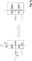
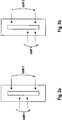
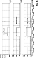
Gemäß dem Ausführungsbeispiel von
- – dass der erste Pfad den ersten Messwiderstand R1, seriell dazu den dritten Messwiderstand R3 und seriell dazu den vierten Messwiderstand R4 aufweist,
- – dass der erste Messwiderstand R1 und der dritte Messwidersand R3 am ersten Verbindungspunkt V1 miteinander verbunden sind,
- – dass der erste Messwiderstand R1 und der vierte Messwiderstand R4 am zweiten Verbindungspunkt V2 miteinander verbunden sind,
- – dass der zweite Pfad den zweiten Messwiderstand R2 aufweist,
- – dass der dritte Messwiderstand R3 und der zweite Messwiderstand R2 am dritten Verbindungspunkt V3 miteinander verbunden sind, und
- – dass der vierte Messwiderstand R4 und der zweite Messwiderstand R2 am vierten Verbindungspunkt V4 miteinander verbunden sind.
- - That the first path has the first measuring resistor R1, in series to the third measuring resistor R3 and serially to the fourth measuring resistor R4,
- That the first measuring resistor R1 and the third measuring resistor R3 are connected to one another at the first connecting point V1,
- - That the first measuring resistor R1 and the fourth measuring resistor R4 are connected to each other at the second connection point V2,
- That the second path has the second measuring resistor R2,
- - That the third measuring resistor R3 and the second measuring resistor R2 are connected to each other at the third connection point V3, and
- - That the fourth measuring resistor R4 and the second measuring resistor R2 are connected to each other at the fourth connection point V4.
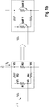
Gemäß dem Ausführungsbeispiel von
- – dass der erste Messwiderstand R1 und der zweite Messwiderstand R2 seriell zueinander geschaltet sind,
- – dass der erste Messwiderstand R1 und der zweite Messeiderstand R2 am ersten Verbindungspunkt V1 miteinander verbunden sind, welcher gleichzeitig den vierten Verbindungspunkt V4 bildet,
- – dass der zweite Verbindungspunkt V2 ein dem ersten Verbindungspunkt V1 gegenüberliegender Pol des ersten Messwiderstands R1 ist, und
- – dass der dritte Verbindungspunkt V3 ein dem vierten Verbindungspunkt V4 gegenüberliegender Pol des zweiten Messwiderstands R2 ist.
- - That the first measuring resistor R1 and the second measuring resistor R2 are connected in series with each other,
- That the first measuring resistor R1 and the second measuring resistor R2 are connected to one another at the first connecting point V1, which simultaneously forms the fourth connecting point V4,
- - That the second connection point V2 is a first connection point V1 opposite pole of the first measuring resistor R1, and
- - That the third connection point V3 is a fourth connection point V4 opposite pole of the second measuring resistor R2.
Bei diesem Ausführungsbeispiel ist im Gegensatz zu den anderen Ausführungsbeispielen lediglich ein Pfad vorgesehen.In this embodiment, in contrast to the other embodiments, only one path is provided.
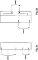
Gemäß dem Ausführungsbeispiel von
- – dass der erste Pfad den ersten Messwiderstand R1 und seriell dazu den dritten Messwiderstand R3 aufweist,
- – dass der erste Messwiderstand R1 und der dritte Messwiderstand R3 am ersten Verbindungspunkt V1 miteinander verbunden sind,
- – dass der zweite Pfad den zweiten Messwiderstand R2 und seriell dazu den vierten Messwiderstand R4 aufweist,
- – dass der zweite Messwiderstand R2 und der vierte Messwiderstand R4 am dritten Verbindungspunkt V3 miteinander verbunden sind,
- – dass der dritte Messwiderstand R3 und der vierte Messwiderstand R4 an einem fünften Verbindungspunkt V5 miteinander verbunden sind, und
- – dass der erste Messwiderstand R1 und der zweite Messwiderstand R2 am zweiten Verbindungspunkt V2 miteinander verbunden sind, welcher gleichzeitig den vierten Verbindungspunkt V4 bildet.
- - That the first path has the first measuring resistor R1 and serially to the third measuring resistor R3,
- - That the first measuring resistor R1 and the third measuring resistor R3 are connected to each other at the first connection point V1,
- - That the second path has the second measuring resistor R2 and serially to the fourth measuring resistor R4,
- - That the second measuring resistor R2 and the fourth measuring resistor R4 are connected to each other at the third connection point V3,
- - That the third measuring resistor R3 and the fourth measuring resistor R4 are connected to one another at a fifth connection point V5, and
- - That the first measuring resistor R1 and the second measuring resistor R2 are connected to each other at the second connection point V2, which simultaneously forms the fourth connection point V4.
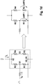
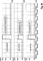
Gemäß dem Ausführungsbeispiel von
- – dass der erste Pfad den ersten Messwiderstand R1 und seriell dazu den dritten Messwiderstand R3 aufweist,
- – dass der zweite Pfad den zweiten Messwiderstand R2 und seriell dazu den vierten Messwiderstand R4 aufweist,
- – dass der erste Messwiderstand R1 und der dritte Messwiderstand R3 am ersten Verbindungspunkt V1 miteinander verbunden sind,
- – dass der zweite Messwiderstand R2 und der vierte Messwiderstand R4 am zweiten Verbindungspunkt V2 miteinander verbunden sind,
- – dass der dritte Messwiderstand R3 und der vierte Messwiderstand R4 an einem weiteren Verbindungspunkt VW miteinander verbunden sind, und
- – dass der erste Messwidersand R1 und der zweite Messwiderstand R2 an noch einem weiteren Verbindungspunkt VNW miteinander verbunden sind.
- - That the first path has the first measuring resistor R1 and serially to the third measuring resistor R3,
- - That the second path has the second measuring resistor R2 and serially to the fourth measuring resistor R4,
- - That the first measuring resistor R1 and the third measuring resistor R3 are connected to each other at the first connection point V1,
- - That the second measuring resistor R2 and the fourth measuring resistor R4 are connected to each other at the second connection point V2,
- - That the third measuring resistor R3 and the fourth measuring resistor R4 are connected to each other at a further connection point VW, and
- - That the first measuring resistance R1 and the second measuring resistor R2 are connected to each other at yet another connection point VNW.
Damit wird bei dem Ausführungsbeispiel von
In diesem Fall kann auch von einer weiteren Möglichkeit für die Anwendung der Methode „gleich verteilter Laststrom, ungleich verteilter Kalibrierstrompuls“ gesprochen werden, wobei der Spannungsabfall einfach differenziell gemessen wird. In diesem Schaltungsbeispiel von
Eine zeitsynchrone Messung aller Messsignale ist grundsätzlich vorteilhaft. Der Widerstandswert bzw. das Widerstandsverhältnis der relevanten Widerstände wird dabei typischerweise so gewählt, dass eine Verrechnung und Extraktion des relevanten Messsignals ohne Laststromanteil möglich und sinnvoll ist.A time-synchronous measurement of all measurement signals is basically advantageous. The resistance value or the resistance ratio of the relevant resistors is typically chosen so that a calculation and extraction of the relevant measurement signal without load current component is possible and useful.
Eine Option für die Signalerfassung bietet ein Lock-In-Verstärker. Dieser Verstärker bietet eine Möglichkeit, sehr schwache Analogsignale zu messen und hat eine sehr gute Unterdrückung von Rauschen und Offset. Ein weiterer Vorschlag für die Signalerfassung wäre die Methode der Modulation und Demodulation (Analog Spectrum Modulation).An option for signal acquisition is provided by a lock-in amplifier. This amplifier offers a possibility to measure very weak analogue signals and has a very good suppression of noise and offset. Another suggestion for signal acquisition would be the Modulation and Demodulation (Analog Spectrum Modulation) method.
Bei den Ausführungsbeispielen der
Bei dem Ausführungsbeispiel der
Bei dem Ausführungsbeispiel der
In den
Bei den
Für das Beispiel wurden dabei folgende Widerstandswerte verwendet:
Beide Pfade haben somit einen identischen Widerstand. Der Gesamtwiderstand beträgt 100 Ohm.Both paths thus have an identical resistance. The total resistance is 100 ohms.
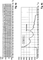
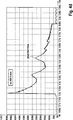
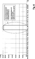
Die
Der durch den Kalibrierstrompuls erzeugte Spannungsabfall ist bei schnellen Laststromänderungen typischerweise schwierig zu detektieren und zu messen. Die abfallende Spannung, welche auf den Kalibrierstrom zurückgeht, liegt in der Größenordnung von μV im Vergleich zu Lastströmen in der Größenordnung von mV.The voltage drop generated by the calibration current pulse is typically difficult to detect and measure during fast load current changes. The falling voltage, which is due to the calibration current, is of the order of magnitude of μV compared to load currents of the order of magnitude of mV.
Die Aufteilung des Laststroms auf die Pfade erfolgt entsprechend der Spannung nach der Knotenregel zu gleichen Teilen, da wie bereits erwähnt die Widerstände der Pfade gleich sind.The distribution of the load current on the paths is equal to the voltage according to the node rule, since, as already mentioned, the resistances of the paths are the same.
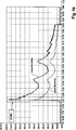
Die
Auch in
Eine resultierende Spannung Ures zur Auswertung kann nur folgendermaßen berechnet werden:
Bei dieser Berechnung wird der Spannungsabfall an R1 auf das gleiche Niveau wie bei R2 gebracht.In this calculation, the voltage drop across R1 is brought to the same level as R2.
Bei dem gegebenen Beispiel, mit den Verhältnis der beiden Widerstandselemente 100μOhm zu 200μOhm, erfolgt dies mit einer einfachen Multiplikation mit 2, d.h. Udiff1 wird mit 2 multipliziert. Somit ist der Anteil des durch den Laststrom hervorgerufenen Spannungsabfalls bei beiden Widerständen gleich groß. Durch die Multiplikation mit 2 wird der Anteil der durch den Kalibrierstrompuls hervorgerufen wird ebenfalls verdoppelt, was sich positiv auf das resultierende Pulssignal auswirkt.In the given example, with the ratio of the two resistive elements 100μOhm to 200μOhm, this is done with a simple multiplication by 2, i. Udiff1 is multiplied by 2. Thus, the proportion of the voltage drop caused by the load current is the same for both resistors. By multiplying by 2, the proportion caused by the Kalibrierstrompuls is also doubled, which has a positive effect on the resulting pulse signal.
Da es durch die Mess- und besondere Schaltungsmethode bei dem ersten Messwiderstand R1 zu einem höheren Kalibrierstromfluss und somit zu einem höheren Spannungsabfall kommt, bleibt nach der einfachen mathematischen Verrechnung, insbesondere Subration der beiden differenziellen Spannungen, ein einfach zu detektierendes Pulssignal übrig.Since a higher calibration current flow and thus a higher voltage drop occur due to the measurement and special circuit method in the case of the first measuring resistor R1, an easy to detect pulse signal remains after the simple mathematical calculation, in particular subration of the two differential voltages.
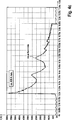
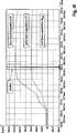
Ein solches Signal, entsprechend dem oben definierten Uref, ist in
Es sei verstanden, dass die obige Vorgehensweise zur Verrechnung der Widerstandswerte allgemein angewendet werden kann, je nach bestimmten Widerstandswerten und/oder sonstigen Gegebenheiten. Die Verrechnung kann dabei digital, also mittels mathematischer Formeln und/oder Algorithmen implementiert sein, insbesondere in einem programmierbaren Bauteil, sie kann jedoch beispielsweise auch analog und/oder schaltungstechnisch implementiert sein.It should be understood that the above approach to offsetting resistance values may be generally applied depending on particular resistance values and / or other circumstances. The calculation can be digital, that is implemented by means of mathematical formulas and / or algorithms, in particular in a programmable component, but it can also be implemented, for example, analog and / or circuit technology.
Die
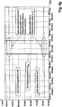
Die
Insgesamt wurde mit dem eben beschriebenen Beispiel gezeigt, dass sich ein Kalibrierstrompuls von einem überlagerten Nutzstrompuls gut trennen lässt, was zur Kalibration eines Messwiderstands vorteilhaft dienen kann, insbesondere zur schnellen und laufenden Kalibrierung während des Betriebs.Overall, it has been shown with the example just described that a calibration current pulse can be easily separated from a superposed useful-current pulse, which can advantageously be used for calibrating a measuring resistor, in particular for rapid and ongoing calibration during operation.
Erwähnte Schritte des erfindungsgemäßen Verfahrens können in der angegebenen Reihenfolge ausgeführt werden. Sie können jedoch auch in einer anderen Reihenfolge ausgeführt werden. Das erfindungsgemäße Verfahren kann in einer seiner Ausführungen, beispielsweise mit einer bestimmten Zusammenstellung von Schritten, in der Weise ausgeführt werden dass keine weiteren Schritte ausgeführt werden. Es können jedoch grundsätzlich auch weitere Schritte ausgeführt werden, auch solche welche nicht erwähnt sind.Mentioned steps of the method according to the invention can be carried out in the order given. However, they can also be executed in a different order. In one of its embodiments, for example with a specific set of steps, the method according to the invention can be carried out in such a way that no further steps are carried out. However, in principle also further steps can be carried out, even those which are not mentioned.
Die zur Anmeldung gehörigen Ansprüche stellen keinen Verzicht auf die Erzielung weitergehenden Schutzes dar. The claims belonging to the application do not constitute a waiver of the achievement of further protection.
Sofern sich im Laufe des Verfahrens herausstellt, dass ein Merkmal oder eine Gruppe von Merkmalen nicht zwingend nötig ist, so wird anmelderseitig bereits jetzt eine Formulierung zumindest eines unabhängigen Anspruchs angestrebt, welcher das Merkmal oder die Gruppe von Merkmalen nicht mehr aufweist. Hierbei kann es sich beispielsweise um eine Unterkombination eines am Anmeldetag vorliegenden Anspruchs oder um eine durch weitere Merkmale eingeschränkte Unterkombination eines am Anmeldetag vorliegenden Anspruchs handeln. Derartige neu zu formulierende Ansprüche oder Merkmalskombinationen sind als von der Offenbarung dieser Anmeldung mit abgedeckt zu verstehen.If, in the course of the procedure, it turns out that a feature or a group of features is not absolutely necessary, it is already desired on the applicant side to formulate at least one independent claim which no longer has the feature or the group of features. This may, for example, be a subcombination of a claim present at the filing date or a subcombination of a claim limited by further features of a claim present at the filing date. Such newly formulated claims or feature combinations are to be understood as covered by the disclosure of this application.
Es sei ferner darauf hingewiesen, dass Ausgestaltungen, Merkmale und Varianten der Erfindung, welche in den verschiedenen Ausführungen oder Ausführungsbeispielen beschriebenen und/oder in den Figuren gezeigt sind, beliebig untereinander kombinierbar sind. Einzelne oder mehrere Merkmale sind beliebig gegeneinander austauschbar. Hieraus entstehende Merkmalskombinationen sind als von der Offenbarung dieser Anmeldung mit abgedeckt zu verstehen.It should also be noted that embodiments, features and variants of the invention, which are described in the various embodiments or embodiments and / or shown in the figures, can be combined with each other as desired. Single or multiple features are arbitrarily interchangeable. Resulting combinations of features are to be understood as covered by the disclosure of this application.
Rückbezüge in abhängigen Ansprüchen sind nicht als ein Verzicht auf die Erzielung eines selbständigen, gegenständlichen Schutzes für die Merkmale der rückbezogenen Unteransprüche zu verstehen. Diese Merkmale können auch beliebig mit anderen Merkmalen kombiniert werden.Recoveries in dependent claims are not to be understood as a waiver of obtaining independent, objective protection for the features of the dependent claims. These features can also be combined as desired with other features.
Merkmale, die lediglich in der Beschreibung offenbart sind oder Merkmale, welche in der Beschreibung oder in einem Anspruch nur in Verbindung mit anderen Merkmalen offenbart sind, können grundsätzlich von eigenständiger erfindungswesentlicher Bedeutung sein. Sie können deshalb auch einzeln zur Abgrenzung vom Stand der Technik in Ansprüche aufgenommen werden.Features that are disclosed only in the specification or features that are disclosed in the specification or in a claim only in conjunction with other features may, in principle, be of independent significance to the invention. They can therefore also be included individually in claims to distinguish them from the prior art.
Claims (15)
Priority Applications (2)
| Application Number | Priority Date | Filing Date | Title |
|---|---|---|---|
| DE102016202501.5A DE102016202501B4 (en) | 2016-02-18 | 2016-02-18 | Method for determining a calibration current pulse |
| PCT/EP2017/053007 WO2017140589A1 (en) | 2016-02-18 | 2017-02-10 | Method for determining a calibration current pulse |
Applications Claiming Priority (1)
| Application Number | Priority Date | Filing Date | Title |
|---|---|---|---|
| DE102016202501.5A DE102016202501B4 (en) | 2016-02-18 | 2016-02-18 | Method for determining a calibration current pulse |
Publications (2)
| Publication Number | Publication Date |
|---|---|
| DE102016202501A1 true DE102016202501A1 (en) | 2017-08-24 |
| DE102016202501B4 DE102016202501B4 (en) | 2022-03-17 |
Family
ID=58057106
Family Applications (1)
| Application Number | Title | Priority Date | Filing Date |
|---|---|---|---|
| DE102016202501.5A Active DE102016202501B4 (en) | 2016-02-18 | 2016-02-18 | Method for determining a calibration current pulse |
Country Status (2)
| Country | Link |
|---|---|
| DE (1) | DE102016202501B4 (en) |
| WO (1) | WO2017140589A1 (en) |
Cited By (1)
| Publication number | Priority date | Publication date | Assignee | Title |
|---|---|---|---|---|
| DE102017219016A1 (en) * | 2017-10-24 | 2019-04-25 | Continental Automotive Gmbh | Method for operating a battery sensor and battery sensor |
Families Citing this family (1)
| Publication number | Priority date | Publication date | Assignee | Title |
|---|---|---|---|---|
| CN112230094B (en) * | 2020-11-11 | 2022-11-29 | 广东电网有限责任公司 | Teaching device for simulating power quality |
Citations (5)
| Publication number | Priority date | Publication date | Assignee | Title |
|---|---|---|---|---|
| DE10310503A1 (en) * | 2003-03-11 | 2004-09-23 | Robert Bosch Gmbh | Current measurement arrangement has a test current source of known value that permits the calibration of a measurement resistance prior to, or during, current measurement processes |
| DE102012006269A1 (en) * | 2011-03-29 | 2012-10-04 | Continental Teves Ag & Co. Ohg | current sensor |
| WO2013000621A1 (en) * | 2011-06-29 | 2013-01-03 | Robert Bosch Gmbh | Method and system for calibrating a shunt resistor |
| DE102013200335A1 (en) * | 2012-01-13 | 2013-07-18 | Infineon Technologies Austria Ag | Circuit arrangement with a load transistor and method for measuring a current through a load transistor |
| US20140191768A1 (en) * | 2013-01-04 | 2014-07-10 | Linear Technology Corporation | Method and system for measuring the resistance of a resistive structure |
Family Cites Families (4)
| Publication number | Priority date | Publication date | Assignee | Title |
|---|---|---|---|---|
| JPS62168067A (en) * | 1986-01-21 | 1987-07-24 | Yamatake Honeywell Co Ltd | Measuring method for resistance value |
| AT414048B (en) * | 2004-07-06 | 2006-08-15 | Lem Norma Gmbh | METHOD AND DEVICE FOR CURRENT MEASUREMENT |
| US8358085B2 (en) * | 2009-01-13 | 2013-01-22 | Terralux, Inc. | Method and device for remote sensing and control of LED lights |
| ES2484816T3 (en) * | 2012-02-02 | 2014-08-12 | Magna Steyr Battery Systems Gmbh & Co Og | Current measurement circuit and procedure to monitor a functional capacity of a current measurement circuit |
-
2016
- 2016-02-18 DE DE102016202501.5A patent/DE102016202501B4/en active Active
-
2017
- 2017-02-10 WO PCT/EP2017/053007 patent/WO2017140589A1/en active Application Filing
Patent Citations (5)
| Publication number | Priority date | Publication date | Assignee | Title |
|---|---|---|---|---|
| DE10310503A1 (en) * | 2003-03-11 | 2004-09-23 | Robert Bosch Gmbh | Current measurement arrangement has a test current source of known value that permits the calibration of a measurement resistance prior to, or during, current measurement processes |
| DE102012006269A1 (en) * | 2011-03-29 | 2012-10-04 | Continental Teves Ag & Co. Ohg | current sensor |
| WO2013000621A1 (en) * | 2011-06-29 | 2013-01-03 | Robert Bosch Gmbh | Method and system for calibrating a shunt resistor |
| DE102013200335A1 (en) * | 2012-01-13 | 2013-07-18 | Infineon Technologies Austria Ag | Circuit arrangement with a load transistor and method for measuring a current through a load transistor |
| US20140191768A1 (en) * | 2013-01-04 | 2014-07-10 | Linear Technology Corporation | Method and system for measuring the resistance of a resistive structure |
Cited By (5)
| Publication number | Priority date | Publication date | Assignee | Title |
|---|---|---|---|---|
| DE102017219016A1 (en) * | 2017-10-24 | 2019-04-25 | Continental Automotive Gmbh | Method for operating a battery sensor and battery sensor |
| WO2019081365A1 (en) * | 2017-10-24 | 2019-05-02 | Continental Automotive Gmbh | Method for operating a battery sensor, and battery sensor |
| CN111263889A (en) * | 2017-10-24 | 2020-06-09 | 大陆汽车有限责任公司 | Method for operating a battery sensor and battery sensor |
| US11181551B2 (en) | 2017-10-24 | 2021-11-23 | Continental Automotive Gmbh | Method for operating a battery sensor, and battery sensor |
| CN111263889B (en) * | 2017-10-24 | 2022-06-21 | 大陆汽车有限责任公司 | Method for operating a battery sensor and battery sensor |
Also Published As
| Publication number | Publication date |
|---|---|
| WO2017140589A1 (en) | 2017-08-24 |
| DE102016202501B4 (en) | 2022-03-17 |
Similar Documents
| Publication | Publication Date | Title |
|---|---|---|
| DE102007046483B4 (en) | Circuit arrangement and method for monitoring electrical insulation | |
| DE202013011690U1 (en) | measuring resistor | |
| EP3449264B1 (en) | Method for determining a load current and battery sensor | |
| DE102017219016A1 (en) | Method for operating a battery sensor and battery sensor | |
| DE102016204941A1 (en) | Method for determining a load current and battery sensor | |
| DE102017223535A1 (en) | Method and battery sensor for determining a load current | |
| DE102018107514A1 (en) | CURRENT MEASURING TECHNIQUES FOR COMPENSATING AN EXTERNAL DRIFT | |
| DE102014108511A1 (en) | resistivity | |
| DE102017203535A1 (en) | Current sensor with optimized current density distribution, method for determining a load current | |
| DE102016202498A1 (en) | Measuring resistance calibration device, method for calibrating a measuring resistor and battery sensor | |
| WO2004070401A1 (en) | Method and circuit arrangement for determining an electric measurement value for a resistance element, preferably for determining an electric current that flows through said resistance element | |
| DE102012019095B4 (en) | Device for monitoring insulation resistance of networks | |
| DE102016202501B4 (en) | Method for determining a calibration current pulse | |
| DE102004056133B4 (en) | Method for detecting an offset drift in a Wheatstone measuring bridge | |
| DE102010055597A1 (en) | Method for determination of parameters of lithium-ion battery in e.g. hybrid vehicle, involves defining parameters by equivalent circuit of vehicle battery, and determining parameters based on neural networks | |
| DE2000255B2 (en) | VOLTAGE COMPARISON ARRANGEMENT | |
| DE102006030337B4 (en) | Method for controlling a seat heating of a vehicle seat, and seat heating | |
| DE10240243A1 (en) | Current measurement arrangement, comprising two current sensors for low and high current ranges, has zero point drift compensation based on combined evaluation of current measurements from both sensors | |
| DE102015210426A1 (en) | Arrangement and method for detecting a current by means of an inductive current sensor | |
| WO2015197230A1 (en) | Method and apparatus for sensing small currents | |
| EP3640651B1 (en) | Operation method of a current sensor and current sensor | |
| WO2016139314A1 (en) | Method and device for leakage-current-compensated resistance measurement | |
| DE2353812B2 (en) | Temperature measurement | |
| DE102013215731A1 (en) | Method and device for measuring one or more insulation resistances in a motor vehicle | |
| DE102020213441B4 (en) | Method of testing an electronic circuit |
Legal Events
| Date | Code | Title | Description |
|---|---|---|---|
| R163 | Identified publications notified | ||
| R012 | Request for examination validly filed | ||
| R016 | Response to examination communication | ||
| R018 | Grant decision by examination section/examining division | ||
| R081 | Change of applicant/patentee |
Owner name: CONTINENTAL AUTOMOTIVE TECHNOLOGIES GMBH, DE Free format text: FORMER OWNER: CONTINENTAL AUTOMOTIVE GMBH, 30165 HANNOVER, DE |
|
| R020 | Patent grant now final | ||
| R081 | Change of applicant/patentee |
Owner name: CONTINENTAL AUTOMOTIVE TECHNOLOGIES GMBH, DE Free format text: FORMER OWNER: CONTINENTAL AUTOMOTIVE TECHNOLOGIES GMBH, 30165 HANNOVER, DE |