DE102016121663A1 - Activating a transmitting device of a lighting device - Google Patents
Activating a transmitting device of a lighting device Download PDFInfo
- Publication number
- DE102016121663A1 DE102016121663A1 DE102016121663.1A DE102016121663A DE102016121663A1 DE 102016121663 A1 DE102016121663 A1 DE 102016121663A1 DE 102016121663 A DE102016121663 A DE 102016121663A DE 102016121663 A1 DE102016121663 A1 DE 102016121663A1
- Authority
- DE
- Germany
- Prior art keywords
- lighting device
- transmitting device
- transmitting
- activation
- emp
- Prior art date
- Legal status (The legal status is an assumption and is not a legal conclusion. Google has not performed a legal analysis and makes no representation as to the accuracy of the status listed.)
- Pending
Links
Images


Classifications
-
- G—PHYSICS
- G01—MEASURING; TESTING
- G01S—RADIO DIRECTION-FINDING; RADIO NAVIGATION; DETERMINING DISTANCE OR VELOCITY BY USE OF RADIO WAVES; LOCATING OR PRESENCE-DETECTING BY USE OF THE REFLECTION OR RERADIATION OF RADIO WAVES; ANALOGOUS ARRANGEMENTS USING OTHER WAVES
- G01S1/00—Beacons or beacon systems transmitting signals having a characteristic or characteristics capable of being detected by non-directional receivers and defining directions, positions, or position lines fixed relatively to the beacon transmitters; Receivers co-operating therewith
- G01S1/02—Beacons or beacon systems transmitting signals having a characteristic or characteristics capable of being detected by non-directional receivers and defining directions, positions, or position lines fixed relatively to the beacon transmitters; Receivers co-operating therewith using radio waves
- G01S1/022—Means for monitoring or calibrating
- G01S1/024—Means for monitoring or calibrating of beacon transmitters
-
- H—ELECTRICITY
- H05—ELECTRIC TECHNIQUES NOT OTHERWISE PROVIDED FOR
- H05B—ELECTRIC HEATING; ELECTRIC LIGHT SOURCES NOT OTHERWISE PROVIDED FOR; CIRCUIT ARRANGEMENTS FOR ELECTRIC LIGHT SOURCES, IN GENERAL
- H05B47/00—Circuit arrangements for operating light sources in general, i.e. where the type of light source is not relevant
- H05B47/10—Controlling the light source
- H05B47/175—Controlling the light source by remote control
- H05B47/19—Controlling the light source by remote control via wireless transmission
-
- G—PHYSICS
- G01—MEASURING; TESTING
- G01S—RADIO DIRECTION-FINDING; RADIO NAVIGATION; DETERMINING DISTANCE OR VELOCITY BY USE OF RADIO WAVES; LOCATING OR PRESENCE-DETECTING BY USE OF THE REFLECTION OR RERADIATION OF RADIO WAVES; ANALOGOUS ARRANGEMENTS USING OTHER WAVES
- G01S5/00—Position-fixing by co-ordinating two or more direction or position line determinations; Position-fixing by co-ordinating two or more distance determinations
- G01S5/02—Position-fixing by co-ordinating two or more direction or position line determinations; Position-fixing by co-ordinating two or more distance determinations using radio waves
- G01S5/0295—Proximity-based methods, e.g. position inferred from reception of particular signals
Landscapes
- Engineering & Computer Science (AREA)
- Computer Networks & Wireless Communication (AREA)
- Physics & Mathematics (AREA)
- General Physics & Mathematics (AREA)
- Radar, Positioning & Navigation (AREA)
- Remote Sensing (AREA)
- Circuit Arrangement For Electric Light Sources In General (AREA)
Abstract
Beleuchtungsvorrichtungen mit Leuchteinrichtung (LM), Sendeeinrichtung (SE) zum Senden eines elektromagnetischen Datensignals und Energiezwischenspeicher (EZ) zur Stromversorgung der Sendeeinrichtung (SE) sollen vor Tiefenentladung geschützt werden. Dazu ist eine Aktivierungseinrichtung (STE, EMP) vorgesehen, mit der die Sendeeinrichtung (SE) von einem Energiesparmodus, in dem die Sendeeinrichtung (SE) abgeschaltet ist, in einen Betriebsmodus, in dem die Sendeeinrichtung (SE) zum betriebsgemäßen Senden des elektromagnetischen Datensignals eingeschaltet ist, aktivierbar ist.Lighting devices with lighting device (LM), transmitting device (SE) for transmitting an electromagnetic data signal and energy buffer (EZ) for powering the transmitting device (SE) are to be protected against deep discharge. For this purpose, an activation device (STE, EMP) is provided, with which the transmitting device (SE) of an energy saving mode in which the transmitting device (SE) is switched off, in an operating mode in which the transmitting device (SE) for operationally transmitting the electromagnetic data signal is turned on is, is activatable.
Description
Die vorliegende Erfindung betrifft eine Beleuchtungsvorrichtung mit einem Leuchtmittel, einer Sendeeinrichtung zum Senden eines elektromagnetischen Datensignals und einem Energiezwischenspeicher zur Stromversorgung der Sendeeinrichtung. Darüber hinaus betrifft die vorliegende Erfindung ein entsprechendes Verfahren zum Betreiben einer derartigen Beleuchtungsvorrichtung.The present invention relates to a lighting device with a luminous means, a transmitting device for transmitting an electromagnetic data signal and an energy buffer for supplying power to the transmitting device. Moreover, the present invention relates to a corresponding method for operating such a lighting device.
Sogenannte „Beacons“ können mit Leuchten kombiniert werden, um leuchtenspezifische oder andere Informationen bereitzustellen. Die Beacon-Technologie basiert auf einem Sender- beziehungsweise Sender-Empfänger-System. Ein Beacon (zu Deutsch: Leuchtfeuer oder auch Bake beziehungsweise Peilsender) ist ein kleiner, meist batteriebetriebener Sender, der ein Signal in (definierbaren) Zeitintervallen typischerweise auf dem Bluetooth-Low-Energy-Standard (BLE) aussendet. Das Funksignal jedes Beacon kennzeichnet sich durch eine einmalige Identifikationsnummer (sogenannte UUID). Beacons können dazu verwendet werden, Objekten und Orten eine digitale Identifikation zu verleihen. Objekte (an denen ein Beacon installiert ist) und Orte (an denen ein Beacon, z.B. an einer Wand installiert ist) können auf diese Weise von Endgeräten (z.B. Smart-Devices) im Signalfeld des Beacon identifiziert werden.So-called "beacons" can be combined with lights to provide light-specific or other information. The beacon technology is based on a transmitter or transceiver system. A beacon is a small, mostly battery-powered transmitter that emits a signal in (definable) time intervals typically on the Bluetooth low-energy standard (BLE). The radio signal of each beacon is characterized by a unique identification number (so-called UUID). Beacons can be used to give objects and places a digital identification. Objects (where a beacon is installed) and locations (where a beacon is installed, for example, on a wall) can thus be identified by terminals (e.g., smart devices) in the signal field of the beacon.
Mithilfe eines Beacon kann beispielsweise ein Ort identifiziert werden beziehungsweise eine Ortung durchgeführt werden. Durch Platzierung eines oder mehrerer Beacons in einem Gebäudeareal entsteht eine Art funkbasiertes Raster, in dem sich ein Smart-Device über die BLE-Schnittstelle sowie entsprechende Algorithmen lokalisieren kann. Die individuellen Identifikationsnummern der installierten Beacons geben einem Ort dabei eine Kennung, anhand der ein Smart-Device näherungsweise die Position bestimmen kann (grundsätzliches Sende-Areal des Beacon kann bestimmt werden). Algorithmen auf dem Smart-Device können die Positionsgenauigkeit z.B. über Signalstärken verbessern. Es ist dabei notwendig, dass das Smart-Device auf Informationen in einer Datenablage (z.B. auf einem Cloud-Server) zugreifen kann (z.B. Identifikationsnummer und eine Kartierung). Kommt ein Endgerät, beispielsweise Smart-Device, in die Reichweite eines Senders, kann es die Identifikationsnummer detektieren und beispielsweise über eine Serverabfrage den Standort bestimmen. Die Ortungsalgorithmen greifen dabei unter anderem auf die empfangene Signalstärke der Beacons im Umkreis zu, insbesondere als Indikator für die Entfernung zum jeweiligen Beacon.With the help of a beacon, for example, a location can be identified or a location can be carried out. Placement of one or more beacons in a building area creates a kind of radio-based grid in which a smart device can locate itself via the BLE interface and corresponding algorithms. The individual identification numbers of the installed beacons give a location an identifier, by means of which a smart device can approximately determine the position (basic transmission area of the beacon can be determined). Algorithms on the smart device may determine the positional accuracy, e.g. improve on signal strengths. It is necessary for the smart device to be able to access information in a repository (e.g., on a cloud server) (e.g., identification number and mapping). If a terminal, for example smart device, comes within the range of a transmitter, it can detect the identification number and, for example, determine the location via a server query. Among other things, the location algorithms access the received signal strength of the beacons in the vicinity, in particular as an indicator for the distance to the respective beacon.
Grundsätzlich können, wie erwähnt wurde, in der Lichttechnik beziehungsweise Beleuchtungstechnik Beacons installiert werden. Dabei wird insbesondere der Vorteil genutzt, dass eine Lichtinstallation einen permanenten Energiezugang bietet, um den Beacon mit Energie zu versorgen. Daraus ergibt sich wiederum der Vorteil, dass die Batterie des Beacon nicht ausgetauscht werden muss und somit entsprechende Lebenszykluskosten beziehungsweise Prozesse eingespart werden können. Darüber hinaus können auch Parametrisierungen des Beacon mit höherem Energieverbrauch eingestellt werden, ohne dass die Lebensdauer des Beacon reduziert wird. Installationsprozesse von Beacon und Lichttechnik können zudem vereinheitlicht werden. Ein weiterer Vorteil ist eine definierte Arretierungsposition eines Beacon-Senders, der gut vor Manipulation geschützt ist. Einem Ort kann somit eine klare und sichere Kennung verliehen werden.Basically, as mentioned, beacons can be installed in lighting or lighting technology. In particular, the advantage is used that a light installation provides a permanent energy access to provide the beacon with energy. This in turn results in the advantage that the battery of the beacon does not have to be replaced and thus corresponding life cycle costs or processes can be saved. In addition, parameterization of the beacon can be set with higher power consumption without reducing the lifetime of the beacon. Installation processes of Beacon and lighting technology can also be standardized. Another advantage is a defined locking position of a beacon transmitter, which is well protected against manipulation. A place can thus be given a clear and secure identifier.
Ein Überblick über Nutzenpotentiale der Integration eines Beacon in eine Lichtinstallation kann folgender Aufzählung entnommen werden:
- - Es kann die Energieversorgung der Lichtinstallation anstatt einer Batterie genutzt werden, um die Lebenszykluskosten des Beacon zu reduzieren.
- - Die Energieversorgung der Lichtinstallation kann genutzt werden, um die Sendeparameter an den Dienst und nicht an die verfügbare Restenergie beziehungsweise die Parameter der Batterie anzupassen (beispielsweise erzeugen häufige Sendezyklen eine hohe Genauigkeit der Dienste, jedoch auch höheren Energieverbrauch).
- - Der Austausch der Batterie konventioneller Beacon birgt Risiken, nämlich beispielsweise im Hinblick auf Fehler in der Handhabung.
- - Die Nicht-Verfügbarkeit der Dienste kann durch eine unterbrechungsfreie Energieversorgung des Beacon vermieden werden.
- - Ein Installationsort unterhalb der Decke ist ideal für die Signalausbreitung des Beacon.
- - Ein Installationsort unterhalb der Decke macht das Gesamtsystem robuster gegen Störungen/Abschattungen durch Objekte auf Höhe der Flurebene im Gegensatz zu einer Installation des Beacon selbst auf Höhe der Flurebene.
- - Ein Beacon kann vor Manipulationen/Fremdzugriffen (versehentlich, mutwillig) geschützt werden.
- - Beleuchtung und Dienste (z.B. Ortungsdienste) können als Gesamtsystem „aus einer Hand“ angeboten werden.
- - Es besteht die Möglichkeit zur Nutzung des sicheren Kommunikationsnetzwerks der Lichtinstallation, um beispielsweise den Beacon zu konfigurieren oder die Beacons untereinander zu vernetzen.
- - Eine Vereinheitlichung der Installationsprozesse von Beacon und Lichtinstallation ist möglich.
- - Weiterhin besteht die Möglichkeit zur Kopplung zu weiteren Systemelementen der peripheren Gebäudeinfrastruktur über das Kommunikationsnetzwerk der Lichtinstallation, z.B. zu Elementen der Sicherheitstechnik.
- - Es kann ein optisch ansprechendes System bereitgestellt werden, da der Beacon nicht sichtbar in der Lichtinstallation untergebracht sein kann.
- - It can be used to power the light installation instead of a battery to reduce the life cycle cost of the beacon.
- - The energy supply of the light installation can be used to adapt the transmission parameters to the service and not to the available residual energy or the parameters of the battery (for example, frequent transmission cycles generate a high accuracy of the services, but also higher energy consumption).
- - Replacing the battery of conventional beacon poses risks, for example, in terms of handling errors.
- - The non-availability of the services can be avoided by an uninterruptible power supply of the beacon.
- - An installation location below the ceiling is ideal for signal propagation of the beacon.
- - An installation location below the ceiling makes the overall system more robust against disturbances / shadows caused by objects at the level of the hall level, in contrast to an installation of the beacon itself at the height of the corridor level.
- - A beacon can be protected against manipulation / foreign access (accidental, wantonly).
- - Lighting and services (eg location services) can be offered as a complete system "from a single source".
- - It is possible to use the secure communication network of the light installation, for example to configure the beacon or to network the beacons with each other.
- - A unification of the installation processes of Beacon and light installation is possible.
- - There is also the possibility of coupling to other system elements of the peripheral building infrastructure via the communication network of the light installation, for example to elements of safety technology.
- - It can be provided a visually appealing system, since the beacon can not be visibly housed in the light installation.
Der Beacon B1 kann mit einem oder mehreren weiteren Beacons B2 in Kommunikationsverbindung KV2 stehen. Ferner kann eine Kommunikationsverbindung KV3 zu einer Infrastruktureinrichtung IE, z.B. Internet oder zentraler Dienste-Server, bestehen. Die Infrastruktureinrichtung kann zur Steuerung und/oder zur Übermittlung von Informationen dienen.The beacon B1 can be in communication connection KV2 with one or more further beacons B2. Further, a communication link KV3 may be connected to an infrastructure device IE, e.g. Internet or central services server. The infrastructure device can serve to control and / or transmit information.
Der lokale Beacon B1 der elektrischen Beleuchtungseinrichtung BE kann als reine Sendeeinrichtung oder aber auch als kombinierte Sende-Empfangs-Einrichtung dienen.The local beacon B1 of the electric lighting device BE can serve as a pure transmission device or else as a combined transmission-reception device.
In einem Einsatzbeispiel haben Menschen und Geräte gegebenenfalls die Herausforderung, sich innerhalb eines Areals zu orientieren, zu navigieren oder andere lokale digitale Dienste ausfindig zu machen beziehungsweise zu nutzen (z.B. Apps oder App-Funktionen, Google Maps, Lightyfy Lichtsteuerung etc.). Die Lichtinstallation mit integriertem Beacon in einem Areal wird für diese Nutzenpotentiale zu einem Ortungs- beziehungsweise Orientierungssystem. Mit der damit realisierbaren Selbstortung des Endgeräts können nun Dienste bereitgestellt werden, wie etwa Navigation oder die Bereitstellung von ortsspezifischen Informationen.In one application example, people and equipment may have the challenge of navigating within an area, navigating, or finding other local digital services (e.g., apps or app features, Google Maps, Lightyfy lighting control, etc.). The light installation with integrated beacon in one area becomes a location or orientation system for these potential benefits. With the thus realizable self-location of the terminal services can now be provided, such as navigation or the provision of location-specific information.
Ein Aspekt der Beacon-Technologie ist die Möglichkeit zur Konfiguration typischer Parameter wie beispielsweise Signalstärke und Sendeintervall des Beacon. Mit unterschiedlichen Konfigurationen können verschiedene Anwendungsszenarien individuell unterstützt werden. Wenn eine hohe Servicequalität (genaue Lokalisierung in kurzen Abständen) gefordert ist (wie z.B. bei einer Indoor-Navigation), sind z.B. sehr kurze Sendeintervalle zu konfigurieren.One aspect of beacon technology is the ability to configure typical parameters such as signal strength and beacon transmission interval. With different configurations different application scenarios can be supported individually. If a high quality of service (accurate localization at short intervals) is required (such as in indoor navigation), e.g. configure very short transmission intervals.
Derzeit werden für die Energieversorgung der Beacon Batterien eingesetzt. Durch die Notwendigkeit, diese Batterien in regelmäßigen Zyklen zu wechseln, ergibt sich ein hoher Aufwand sowie entsprechend hohe Lebenszykluskosten für den Beacon.Currently the Beacon batteries are used for the energy supply. The need to change these batteries in regular cycles, results in a high cost and correspondingly high life cycle costs for the beacon.
Eine hohe Service-Qualität - beispielsweise hohe Ortungsgenauigkeit, hohe Reichweite, kurzes Sendeintervall - benötigt vergleichsweise viel Energie beim Sender-Modul, sodass die Batterie eines batteriebetriebenen Beacon nach kurzer Zeit (z.B. nach einem Monat) ausgetauscht werden muss. Jeder Austausch einer Batterie birgt zudem das Risiko, dass die Funktionalität des Ortungssystems durch eine kleine Positionsveränderung oder falsche Handhabung des Beacon nachteilig beeinflusst wird.High service quality - such as high positioning accuracy, long range, short transmission interval - requires comparatively much energy at the transmitter module, so that the battery of a battery-powered beacon must be replaced after a short time (for example, after one month). Any replacement of a battery also carries the risk that the functionality of the positioning system is adversely affected by a small change in position or incorrect handling of the beacon.
Gegebenenfalls besteht die Gefahr, dass der Betreiber (z.B. Besitzer eines Supermarkts) sich des Energiemangels des Beacon nicht bewusst ist bzw. den Beacon nicht wiederfindet, wenn keine ausreichende Restenergie mehr vorhanden ist. Die Dienste des Beacon (z.B. Navigation) sollten dem Nutzer jedoch permanent zur Verfügung stehen. Dies erfordert eine unterbrechungsfreie Energieversorgung.If necessary, there is a risk that the operator (e.g., a supermarket owner) will be unaware of the beacon's energy deficiency or will not find the beacon if sufficient residual energy is left. The services of the beacon (e.g., navigation) should be permanently available to the user. This requires an uninterruptible power supply.
Die Anbringung bzw. Installation der Beacon an/in oder als Teil der Lichtinstallation bzw. eines Leuchtmittels würde es gegenüber einem batterie-betriebenen Beacon ermöglichen, die Energieversorgung der Lichtinstallation (z.B. Vorschaltgerät der Leuchte bzw. des Leuchtmittels) für die Energieversorgung des Beacon zu nutzen und somit die Batterie des Beacon zu substituieren und den damit verbundenen Problemstellungen (vergleiche oben) entgegenzuwirken.The installation or installation of the beacon on / in or as part of the light installation or a light source would allow compared to a battery-powered beacon to use the power supply of the light installation (eg ballast of the light or the bulb) for the power supply of the beacon and thus replace the battery of the beacon and counteract the problems associated with it (see above).
Es werden hier demnach Sende-Empfangs-Vorrichtungen bzw. Sende-Vorrichtungen (z.B. Beacon) in/an oder als Teil einer Lichtinstallation/Leuchte bzw. eines Leuchtmittels (nachfolgend kurz Leuchteinrichtung genannt) betrachtet, wobei die Vorrichtung über die Leuchteinrichtung mit Energie versorgt wird. Gleichzeitig ist mindestens ein Energie-Zwischenspeicher (z.B. Akku, Kondensator) Teil des Gesamtsystems. Dieser stellt der Sende-Empfangsvorrichtung, beispielsweise dem Beacon, die notwendige Energie im Betrieb zur Verfügung, wenn die Energieversorgung durch die Leuchteinrichtung unterbrochen ist (z.B. im Falle, dass die Leuchte ausgeschaltet ist und kein Licht emittiert).There are therefore here considered transceiver devices or transmitting devices (eg beacon) in / on or as part of a light installation / luminaire or a light source (hereinafter referred to as lighting device), wherein the device is powered by the lighting device with energy , At the same time, at least one energy buffer (e.g., battery, capacitor) is part of the overall system. This provides the necessary power to the transceiver, such as the beacon, when power is interrupted by the light device (e.g., in the event that the light is off and does not emit light).
Bei der Produktion wird beispielsweise ein vorgeladener Energie-Zwischenspeicher (z.B. Akku) in das Gesamtsystem montiert bzw. im Rahmen des Montageprozesses installiert. Die Sende-Empfangsvorrichtung befindet sich jedoch in einem Zustand, in dem konstant Strom verbraucht wird, sodass es im Verlauf der nachfolgenden Logistikprozesse bis zur Installation bzw. Inbetriebnahme des Gesamtsystems im Service-Areal zu einer Tiefentladung des Energiezwischenspeichers kommen kann.During production, for example, a preloaded energy buffer (eg battery) is mounted in the overall system or installed as part of the assembly process. The transmission Receiving device is, however, in a state in which constant power is consumed, so that it may come in the course of the subsequent logistics processes until the installation or commissioning of the entire system in the service area to a deep discharge of the intermediate energy storage.
Die Aufgabe der vorliegenden Erfindung besteht darin, vor Inbetriebnahme einer Beleuchtungsvorrichtung, die eine Sendeeinrichtung und einen Energiezwischenspeicher aufweist, eine Tiefentladung des Energiezwischenspeichers zu vermeiden.The object of the present invention is to avoid a deep discharge of the energy buffer before starting up a lighting device having a transmitting device and an energy buffer.
Erfindungsgemäß wird diese Aufgabe durch eine Beleuchtungsvorrichtung nach Anspruch 1 sowie ein Verfahren nach Anspruch 20 gelöst. Vorteilhafte Weiterbildungen der Erfindung ergeben sich aus den Unteransprüchen. According to the invention this object is achieved by a lighting device according to claim 1 and a method according to claim 20. Advantageous developments of the invention will become apparent from the dependent claims.
Erfindungsgemäß wird demnach eine Beleuchtungsvorrichtung mit einer Leuchteinrichtung, einer Sendeeinrichtung zum Senden eines elektromagnetischen Datensignals und einem Energiezwischenspeicher zur Stromversorgung der Sendeeinrichtung bereitgestellt. Bei der Leuchteinrichtung kann es sich um eine beliebige Einrichtung handeln, mit der Räume bzw. Areale beleuchtet werden können. Die Sendeeinrichtung kann ein elektromagnetisches Datensignal aussenden, das in der Regel nicht sichtbar ist. Beispielsweise erfolgt das Senden nach dem BLE-Standard (Bluetooth-Low-Energy). Das Senden kann aber auch mit einer anderen Technologie erfolgen. Insbesondere können als Sendeeinrichtungen sogenannte Beacon benutzt werden. Damit eine unterbrechungsfreie Stromversorgung der Sendeeinrichtung gewährleistet ist, ist die Beleuchtungsvorrichtung mit einem Energiezwischenspeicher zur Stromversorgung der Sendeeinrichtung ausgestattet. So kann beispielsweise im normalen Betrieb der Beleuchtungsvorrichtung die Energieversorgung der Sendeeinrichtung über die Leuchteinrichtung, d.h. das Leuchtmittel bzw. die Leuchte/Lichtinstallation erfolgen und bei abgeschalteter Leuchteinrichtung erfolgt die Energieversorgung der Sendeeinrichtung über den Energiezwischenspeicher.According to the invention, a lighting device is provided with a lighting device, a transmitting device for transmitting an electromagnetic data signal and an energy buffer for supplying power to the transmitting device. The lighting device can be any device with which rooms or areas can be illuminated. The transmitting device can emit an electromagnetic data signal, which is usually not visible. For example, the transmission takes place according to the BLE standard (Bluetooth low energy). Sending can also be done with a different technology. In particular, so-called beacons can be used as transmitting devices. In order for an uninterruptible power supply of the transmitting device is ensured, the lighting device is equipped with a power buffer for powering the transmitting device. For example, during normal operation of the lighting device, the power supply of the transmitting device may be supplied via the lighting device, i. the light source or the light / light installation take place and when the lighting device is switched off, the energy supply of the transmitting device via the energy buffer.
Weiterhin ist die Beleuchtungsvorrichtung mit einer Aktivierungseinrichtung ausgestattet, mit der die Sendeeinrichtung von einem Energiesparmodus, in dem die Sendeeinrichtung abgeschaltet ist, in einen Betriebsmodus, in dem die Sendeeinrichtung zum betriebsgemäßen Senden des elektromagnetischen Datensignals eingeschaltet ist, aktivierbar ist. Dies bedeutet, dass eine spezielle Aktivierungseinrichtung vorgesehen ist, um die Sendeeinrichtung zu aktivieren. Erst in diesem aktivierten Modus, d.h. dem Betriebsmodus, verbraucht die Sendeeinrichtung die zum Senden übliche Betriebsleistung. In dem Energiesparmodus vor der Aktivierung verbraucht die Sendeeinrichtung nur einen Bruchteil dieser Betriebsleistung, der insbesondere mindestens eine Größenordnung darunter liegt. Auf diese Weise ist es möglich, dass die Sendeeinrichtung erst dann wesentlich Energie verbraucht, wenn sie bewusst aktiviert wurde. Dies erfolgt üblicherweise erst dann, wenn sich die Beleuchtungsvorrichtung im Einsatz befindet.Furthermore, the lighting device is equipped with an activation device with which the transmitting device can be activated from an energy-saving mode in which the transmitting device is switched off into an operating mode in which the transmitting device is switched on for operationally transmitting the electromagnetic data signal. This means that a special activation device is provided to activate the transmitting device. Only in this activated mode, i. the operating mode, the transmitting device consumes the usual operating power for transmission. In the energy-saving mode before activation, the transmitting device consumes only a fraction of this operating power, which is in particular at least an order of magnitude lower. In this way, it is possible that the transmitting device consumes much energy only when it was deliberately activated. This usually takes place only when the lighting device is in use.
Vorzugsweise besitzt die Beleuchtungsvorrichtung einen Netzversorgungsanschluss, über den sowohl die Leuchteinrichtung als auch die Sendeeinrichtung und/oder der Energiezwischenspeicher mit Energie versorgbar ist. Damit besteht der große Vorteil, dass sowohl die Sendeeinrichtung als auch die Leuchteinrichtung über einen gemeinsamen Anschluss mit Energie versorgt werden können. Eine separate Energieversorgung der Sendeeinrichtung ist damit nicht notwendig.Preferably, the lighting device has a power supply connection, via which both the lighting device and the transmitting device and / or the energy buffer can be supplied with energy. This has the great advantage that both the transmitting device and the lighting device can be supplied with energy via a common connection. A separate power supply of the transmitting device is therefore not necessary.
In einer besonderen Ausgestaltung sind die Leuchteinrichtung, die Sendeeinrichtung, der Energiezwischenspeicher und die Aktivierungseinrichtung in einem gemeinsamen Gehäuse untergebracht. Dies bedeutet, dass es sich bei der Beleuchtungsvorrichtung um ein Modul bzw. eine kompakte Vorrichtung handelt, die sich einfach installieren lässt.In a particular embodiment, the lighting device, the transmitting device, the energy buffer and the activation device are housed in a common housing. This means that the lighting device is a module or a compact device that is easy to install.
Gemäß einer Weiterbildung ist die Sendeeinrichtung durch die Aktivierungseinrichtung im Betriebsmodus in einen Sende-Empfangsbetrieb und/oder einen Konfigurationsbetrieb schaltbar. Dies bedeutet, dass mit der Aktivierungseinrichtung nicht nur die Möglichkeit besteht, von dem Energiesparmodus in den Betriebsmodus zu schalten, sondern auch innerhalb des Betriebsmodus zwischen einem Sende-Empfangsbetrieb und einem Konfigurationsbetrieb zu wechseln. Damit besteht eine hohe Flexibilität insbesondere bei der Installation.According to a development, the transmitting device can be switched by the activation device in the operating mode into a transceiver mode and / or a configuration mode. This means that not only does the activation device have the option of switching from the energy-saving mode to the operating mode, but also to switch between a transceiver mode and a configuration mode within the operating mode. This ensures high flexibility, especially during installation.
Weiterhin kann die Aktivierungseinrichtung einen Fotodetektor aufweisen, mit dem ein Lichtimpuls zu dem Aktivieren der Sendeeinrichtung oder zu dem Schalten der Sendeeinrichtung detektierbar ist. In vorteilhafter Weise kann damit die Aktivierungseinrichtung über Lichtimpulse bzw. Blitze gesteuert werden. Hierzu kann beispielsweise das Blitzlicht eines Smartphones verwendet werden. Der Fotodetektor muss nicht darauf beschränkt sein, sichtbares Licht zu detektieren, sondern er kann beispielweise auch Infrarotlicht detektieren.Furthermore, the activation device can have a photodetector with which a light pulse for activating the transmitting device or for switching the transmitting device can be detected. In an advantageous manner, the activation device can thus be controlled via light pulses or flashes. For this example, the flash of a smartphone can be used. The photodetector need not be limited to detecting visible light, but it may also detect infrared light, for example.
In einer speziellen Variante kann vorgesehen sein, dass die Sendeeinrichtung von der Aktivierungseinrichtung zyklisch aktivierbar ist. Dies bedeutet, dass die Sendeeinrichtung in vorbestimmten zeitlichen Abständen (z.B. eine Minute) automatisch aktiviert wird. Liegt dann beispielsweise keine Verbindungsanfrage vor, so kann automatisch wieder eine Deaktivierung erfolgen. Andernfalls kann die Sendeeinrichtung aktiviert bleiben.In a special variant, it can be provided that the transmitting device can be activated cyclically by the activating device. This means that the transmitting device is automatically activated at predetermined time intervals (eg one minute). If, for example, there is no connection request, then automatically one can again Deactivation done. Otherwise, the transmitting device may remain activated.
Die Sendeeinrichtung kann ferner so ausgebildet sein, dass sie nach jedem Aktivieren ein Signal sendet und überprüft, ob eine Verbindungsanfrage vorliegt. Dies bedeutet, dass die Sendeeinrichtung überprüft, ob eine Aktivierung von außen tatsächlich gewünscht ist. Nur so kann verhindert werden, dass die Sendeeinrichtung nach einer automatischen Aktivierung übermäßig lang in Betrieb bleibt.The transmitting device can also be designed such that it sends a signal after every activation and checks whether there is a connection request. This means that the transmitting device checks whether external activation is actually desired. Only in this way can it be prevented that the transmitting device remains in operation for an excessively long time after an automatic activation.
Darüber hinaus kann die Aktivierungseinrichtung derart ausgebildet sein, dass die Sendeeinrichtung automatisch aktiviert wird, sobald die Beleuchtungsvorrichtung von einer externen Energieversorgungseinrichtung mit Energie versorgt wird. Die Sendeeinrichtung kann also beispielsweise dadurch automatisch aktiviert werden, dass sie an ein Energieversorgungsnetz angeschlossen wird. Die Überprüfung erfolgt beispielsweise anhand einer Messung eines Spannungspegels. Auf diese Weise kann sichergestellt werden, dass die Sendeeinrichtung im Wesentlichen nur dann Energie verbraucht, wenn sie an ein Energieversorgungsnetz angeschlossen ist.In addition, the activation device can be designed such that the transmitting device is automatically activated as soon as the lighting device is supplied with energy from an external power supply device. The transmitting device can thus be activated automatically, for example, by being connected to a power supply network. The check is made, for example, by measuring a voltage level. In this way it can be ensured that the transmitting device essentially only consumes energy when it is connected to a power supply network.
Gegebenenfalls ist eine Eingangsspannung der Beleuchtungsvorrichtung von einem Digital-Analogwandler erfassbar und ein entsprechender Wert digital an die Aktivierungseinrichtung übertragbar oder von der Energieversorgungseinrichtung über eine Kommunikationsschnittstelle der Beleuchtungsvorrichtung an die Aktivierungseinrichtung übermittelbar. Der Anlog-Digitalwandler ist vorzugsweise zwischen einer Batterie und einer Recheneinheit der Aktivierungseinrichtung angeordnet. Alternativ kann eine Steuerungseinheit der Energieversorgungseinrichtung den Spannungswert über die Kommunikationsschnittstelle übermitteln.Optionally, an input voltage of the lighting device can be detected by a digital-to-analog converter and a corresponding value can be digitally transmitted to the activation device or transmitted from the power supply device to the activation device via a communication interface of the lighting device. The analogue to digital converter is preferably arranged between a battery and a computing unit of the activation device. Alternatively, a control unit of the power supply device can transmit the voltage value via the communication interface.
Die Aktivierungseinrichtung kann eine Recheneinheit aufweisen, mit der die Art der Energieversorgung der Sendeeinrichtung oder ein Ladezustand des Energiezwischenspeichers erkennbar ist. Diese Erkennung kann beispielsweise anhand der Höhe eines Spannungswerts oder anderer Charakteristiken erfolgen.The activation device can have a computing unit with which the type of energy supply of the transmitting device or a state of charge of the energy buffer can be detected. This detection may be done, for example, based on the magnitude of a voltage value or other characteristics.
Ferner kann die Aktivierungseinrichtung dazu ausgebildet sein, im Falle einer externen Stromversorgung zu entscheiden, dass die Sendeeinrichtung trotz eines aktivierten Tiefentladeschutz aktiviert werden darf. Wenn also Netzversorgung vorliegt, hat das Aktivieren eine höhere Priorität als ein eventuell eingestellter Tiefentladeschutz.Furthermore, the activation device can be designed to decide in the case of an external power supply that the transmission device may be activated despite an activated total discharge protection. So if mains supply is present, the activation has a higher priority than a possibly set Tiefentladeschutz.
Ebenso kann die Aktivierungseinrichtung dazu ausgebildet sein, im Falle interner Stromversorgung zu entscheiden, dass die Sendeeinrichtung trotz eines aktivierten Tiefentladeschutzes aktiviert wird oder werden darf. Dabei kann die Aktivierungseinrichtung insbesondere dazu ausgebildet sein, regelmäßige Schaltzyklen der Sendeeinrichtung zu erkennen. Somit erkennt bzw. approximiert das System, dass es in einer Lichtinstallation verbaut ist und daher in absehbarer Zeit erneut mit Strom zum Aufladen des Akkus versorgt werden wird.Likewise, the activation device may be designed to decide in the case of internal power supply that the transmitting device is activated or may be activated despite an activated deep discharge protection. In this case, the activation device can in particular be designed to recognize regular switching cycles of the transmitting device. Thus, the system recognizes or approximates that it is installed in a light installation and therefore will be supplied again in the foreseeable future with power for charging the battery.
Die Beleuchtungsvorrichtung kann außerdem dazu ausgebildet sein, dass die Sendeeinrichtung nicht in den Energiesparmodus wechselt, nachdem eine externe Stromversorgung für einen vorgegebenen Zeitraum erfolgt ist. Beispielsweise ist das System so vorkonfiguriert, dass es bei einer bestimmten Stromversorgungszeit (z.B. länger als zwei Stunden) nicht mehr in einen Tiefenentladungsschutz wechseln darf bzw. dass es nicht mehr in einen Modus wechseln darf, in dem die Sendeeinrichtung ohne weiteres deaktiviert wird. So ist es auch möglich, dass das System bei erstmaliger externer Stromversorgung selbstständig in einen Modus wechselt, in dem es die Sendeeinheit aktiviert, ohne diese selbstständig wieder zu deaktivieren.The lighting device can also be designed such that the transmitting device does not change into the energy-saving mode after an external power supply has been effected for a predetermined period of time. For example, the system is preconfigured such that it may no longer switch to deep discharge protection for a given power supply time (e.g., longer than two hours), or it may not switch to a mode in which the sending device is readily deactivated. So it is also possible that the system automatically switches to the first external power supply in a mode in which it activates the transmitting unit, without automatically deactivate it again.
Gemäß einer weiteren Ausführungsform wird eine Funktionalität der Beleuchtungsvorrichtung und insbesondere der Sendeeinrichtung automatisch eingeschränkt, wenn der Ladezustand des Energiezwischenspeichers einen vorgegebenen Grenzwert unterschreitet. So wird beispielsweise ab einem bestimmten Akkuladezustand, der ebenfalls ausgelesen werden kann, die Funktionalität des Systems bzw. der Sendeeinrichtung stark eingeschränkt, um den Stromverbrauch zusätzlich zu minimieren (z.B. kein Prüfen der Batterie, kein Senden mehr, etc.). Gegebenenfalls erfolgt nur noch eine schaltungstechnische Prüfung auf externe Stromversorgung.According to a further embodiment, a functionality of the lighting device and in particular of the transmitting device is automatically restricted if the state of charge of the energy buffer falls below a predetermined limit value. Thus, for example, from a certain battery state, which can also be read, the functionality of the system or the transmitting device is severely limited, in order to additionally minimize the power consumption (for example, no checking of the battery, no more sending, etc.). If necessary, only a circuit test for external power supply takes place.
Zudem kann die Aktivierungseinrichtung dazu ausgebildet sein, eine Stromversorgung der Beleuchtungsvorrichtung in vorgegebenen Intervallen zu prüfen und die Sendeeinrichtung entsprechend zu steuern. So steuert beispielsweise die Recheneinheit der Aktivierungseinrichtung die Sendeeinrichtung sowie die oben genannten Prüfintervalle bzw. Abfragungen der Stromversorgung.In addition, the activation device can be designed to check a power supply of the illumination device at predetermined intervals and to control the transmission device accordingly. Thus, for example, the arithmetic unit of the activation device controls the transmitting device and the above-mentioned test intervals or queries of the power supply.
In einer weiteren Ausgestaltung ist die Aktivierungseinrichtung derart ausgebildet, dass die Sendeeinrichtung aktiviert wird, sobald über eine externe Energieversorgungseinrichtung ein vorgegebenes Aktivierungsmuster an die Beleuchtungsvorrichtung übertragen wird. Es genügt also nicht allein das Anschließen der Beleuchtungsvorrichtung an eine Energieversorgungseinrichtung, sondern diese muss zur Aktivierung ein Signal mit einem vorgegebenen Aktivierungsmuster an die Beleuchtungsvorrichtung übertragen. Damit kann die Sendeeinrichtung einer Beleuchtungsvorrichtung beispielsweise mithilfe eines Lichtschalters, mit dem das Aktivierungsmuster erzeugt wird, aktiviert werden.In a further embodiment, the activation device is designed such that the transmission device is activated as soon as a predetermined activation pattern is transmitted to the illumination device via an external power supply device. So it is not enough to connect the lighting device to a power supply device, but this must transmit a signal with a predetermined activation pattern to the lighting device for activation. Thus, the transmitting device of a lighting device, for example, using a light switch, with which the activation pattern is generated, are activated.
Zudem kann die Beleuchtungsvorrichtung neben dem Energiezwischenspeicher zusätzlich eine Batterie zur Versorgung der Sendeeinrichtung aufweisen, wobei die Batterie von der Sendeeinrichtung automatisch elektrisch trennbar ist, wenn die Beleuchtungsvorrichtung von einer externen Energieversorgungseinrichtung Energie bezieht. Somit wird die Energie der Batterie nur solange verbraucht, bis die Beleuchtungsvorrichtung an eine externe Energieversorgung angeschlossen ist. Damit kann die Batterie beispielsweise die Sendeeinrichtung vor der Installation mit Energie versorgen.In addition, in addition to the energy buffer, the lighting device can additionally have a battery for supplying the transmitting device, wherein the battery is automatically electrically separable from the transmitting device when the lighting device receives energy from an external energy supply device. Thus, the power of the battery is consumed only until the lighting device is connected to an external power supply. This allows the battery, for example, to supply the transmitting device with energy prior to installation.
Gemäß einer Weiterbildung enthält die Aktivierungseinrichtung ein Isolierelement, durch dessen Entfernen die Sendeeinrichtung von dem Energiesparmodus in den Betriebsmodus geschaltet wird. Somit kann beispielweise eine galvanische Trennung des Stromkreises der Sendeeinrichtung von dem Energiezwischenspeicher erfolgen, solange die Dienste der Sendeeinrichtung nicht benötigt werden.According to a development, the activation device contains an insulating element, by the removal of which the transmitting device is switched from the energy-saving mode into the operating mode. Thus, for example, a galvanic isolation of the circuit of the transmitting device of the intermediate energy storage can be done as long as the services of the transmitting device are not needed.
Die oben genannte Aufgabe wird erfindungsgemäß auch gelöst durch ein Verfahren zum Betreiben einer Beleuchtungsvorrichtung mit einer Leuchteinrichtung, einer Sendeeinrichtung zum Senden eines elektromagnetischen Datensignals und einem Energiezwischenspeicher zur Stromversorgung der Sendeeinrichtung, durch Aktivieren der Sendeeinrichtung mittels einer Aktivierungseinrichtung der Beleuchtungsvorrichtung von einem Energiesparmodus, in dem die Sendeeinrichtung abgeschaltet ist, in einen Betriebsmodus, in dem die Sendeeinrichtung zum betriebsgemäßen Senden des elektromagnetischen Datensignals eingeschaltet ist.The above object is also achieved by a method for operating a lighting device with a lighting device, a transmitting device for transmitting an electromagnetic data signal and an energy buffer for powering the transmitting device, by activating the transmitting device by means of an activation device of the lighting device of a power saving mode in which the Transmitter is turned off, in an operating mode in which the transmitting device is turned on for proper transmission of the electromagnetic data signal.
Die oben im Zusammenhang mit der erfindungsgemäßen Beleuchtungsvorrichtung geschilderten Vorteile und Weiterbildungen sind sinngemäß auch auf das erfindungsgemäße Verfahren anwendbar. Hierbei werden die entsprechenden funktionellen Merkmale der Mittel der Beleuchtungsvorrichtung als Verfahrensmerkmale des Verfahrens betrachtet.The above described in connection with the lighting device according to the invention advantages and developments are mutatis mutandis applicable to the inventive method. In this case, the corresponding functional features of the means of the lighting device are considered as process features of the method.
Die vorliegende Erfindung wird nun anhand der beigefügten Zeichnungen näher erläutert, in denen zeigen:
-
1 eine schematische Darstellung der Integration eines Beacon in eine Lichtinstallation gemäß dem Stand der Technik; -
2 ein Konzept einer Beleuchtungsvorrichtung mit einer Aktivierung der Sendeeinrichtung über ein optisches Signal; -
3 ein Konzept einer Beleuchtungsvorrichtung mit unmittelbarer Aktivierung der Sendeeinrichtung, wenn diese mit Energie versorgt wird; und -
4 ein Konzept eine Beleuchtungsvorrichtung, deren Sendeeinrichtung mit einem Aktivierungsmuster aktivierbar ist.
-
1 a schematic representation of the integration of a beacon in a light installation according to the prior art; -
2 a concept of a lighting device with an activation of the transmitting device via an optical signal; -
3 a concept of a lighting device with immediate activation of the transmitter when it is powered; and -
4 a concept of a lighting device whose transmitting device can be activated with an activation pattern.
Die nachfolgend näher geschilderten Ausführungsbeispiele stellen bevorzugte Ausführungsformen der vorliegenden Erfindung dar. Dabei ist zu beachten, dass die einzelnen Merkmale nicht nur in den geschilderten Merkmalskombinationen, sondern auch in Alleinstellung oder in anderen technisch sinnvollen Merkmalskombinationen realisiert werden können.The embodiments described in more detail below represent preferred embodiments of the present invention. It should be noted that the individual features can be realized not only in the described feature combinations, but also in isolation or in other technically meaningful combinations of features.
Ziel ist es, beispielsweise ein Beacon-Speichersystem vor Tiefentladungen zu schützen. Dazu kann ein technisches System bzw. eine Anordnung bereitgestellt werden, welches eine Sende-Empfangseinrichtung oder Sendeeinrichtung (nachfolgend kurz Sendeeinrichtung) in/an oder als Teil einer Leuchte/Lichtinstallation bzw. eines Leuchtmittels (nachfolgend kurz „an der Leuchteinrichtung“) sowie einen Energiezwischenspeicher umfasst, welcher der Sendeeinrichtung, beispielsweise dem Beacon, die notwendige Energie im Betrieb zur Verfügung stellt, wenn die Energieversorgung durch die Leuchteinrichtung unterbrochen ist. Das System verfügt weiterhin über einen Aktivierungsmechanismus beziehungsweise eine Aktivierungseinrichtung (z.B. manuell/mechanisch/Software/über Blitzgerät eines Smart-Devices), um aus einem Energiesparmodus in einen Betriebsmodus zu wechseln und den Energiezwischenspeicher vor eine Tiefentladung zu schützen.The goal is to protect, for example, a beacon memory system from deep discharges. For this purpose, a technical system or an arrangement can be provided, which includes a transmitting-receiving device or transmitting device (hereinafter briefly transmitting device) in / on or as part of a lamp / light installation or a lighting means (hereinafter "on the lighting device") and an intermediate energy storage comprising which of the transmitting device, for example the beacon, provides the necessary energy during operation when the power supply is interrupted by the lighting device. The system further includes an activation mechanism (e.g., manual / mechanical / software / flash device of a smart device) to change from a power-saving mode to an operating mode and to protect the power cache from over-discharge.
Die Sendeeinrichtung an der Leuchteinrichtung wird vorzugsweise über die Leuchteinrichtung mit Energie versorgt. Die Sendeeinrichtung sendet beispielsweise eine eindeutige Identifikationsnummer zyklisch aus. Eine Möglichkeit, bei der kein aufwendiger Energiewandler benötigt wird, ist der elektrische Anschluss der Sendeeinrichtung parallel zu der Leuchteinrichtung wie LED-Modulen bzw. zu einer Gruppe von LEDs oder unter Umständen zu einem LCD-Trägermodul.The transmitting device on the lighting device is preferably powered by the lighting device with energy. The transmitting device transmits, for example, a unique identification number cyclically. One possibility in which no complex energy converter is required is the electrical connection of the transmitting device parallel to the lighting device such as LED modules or to a group of LEDs or possibly to an LCD carrier module.
Weiterhin ist ein Energie-Zwischenspeicher (z.B. Akku) Teil des Gesamtsystems beziehungsweise der Beleuchtungsvorrichtung. Dieser stellt der Sendeeinrichtung, beispielsweise dem Beacon, die notwendige Energie im Betrieb zur Verfügung, wenn die Energieversorgung durch die Leuchteinrichtung unterbrochen ist. Ein Beispiel für eine derartige Situation stellt die Inbetriebnahme bzw. Installation der Leuchteinrichtung dar, in welcher gegebenenfalls der Dienst der Sendeeinrichtung zur ortsbezogenen Identifikation notwendig ist, ohne dass die externe Energieversorgung über die Hausversorgung zur Verfügung steht.Furthermore, an energy buffer (e.g., battery) is part of the overall system or lighting device. This provides the transmitting device, for example the beacon, the necessary energy during operation when the power supply is interrupted by the lighting device. An example of such a situation is the commissioning or installation of the lighting device in which, where appropriate, the service of the transmitting device for location-based identification is necessary without the external power supply is available through the home supply.
Eine mögliche Ergänzung dieser Ausprägung sieht vor, dass die Sendeeinrichtung an der Leuchteinrichtung im Falle einer bevorstehenden vollständigen oder nahezu vollständigen Entladung des Energiezwischenspeichers über eine Kommunikationsverbindung zu der Leuchteinrichtung eine Steuerinformation an dieses sendet, sodass die Leuchteinrichtung angeschaltet und der Energiezwischenspeicher somit wieder geladen wird. Dabei muss die Leuchteinrichtung nicht zwingend Licht emittieren. Somit kann die Sendeeinrichtung die Leuchte in ausgewählten Situationen steuern (z.B. An-/Ausschalten) und somit den eigenen Energiezustand kontrollieren. A possible supplement to this embodiment provides that the transmitting device to the lighting device in the event of an imminent complete or almost complete discharge of the energy buffer memory via a communication link to the lighting device sends a control information to this, so that the lighting device is turned on and the energy buffer is thus loaded again. The lighting device does not necessarily have to emit light. Thus, the transmitting device can control the light in selected situations (eg on / off switching) and thus control its own energy state.
Im Rahmen einer möglichen Umsetzung dieser Lösung wird ein Konverter zwischen das Beacon und das elektronische Vorschaltgerät des Leuchtmittels geschaltet, welcher die Daten der Sendeeinrichtung (z.B. des Beacon-Chips) in ein DALI-Format übersetzt. Der Konverter kann dabei Teil der Sendeeinrichtung sein und/oder als separates Systemelement ausgeführt sein und/oder Teil der Leuchteinrichtung sein, insbesondere in das elektronische Vorschaltgerät integriert werden.As part of a possible implementation of this solution, a converter is connected between the beacon and the electronic ballast of the light source, which translates the data of the transmitting device (e.g., the beacon chip) into a DALI format. The converter can be part of the transmitting device and / or be designed as a separate system element and / or be part of the lighting device, in particular integrated into the electronic ballast.
Die Beleuchtungsvorrichtung verfügt über einen Energiesparmodus, d.h. einzelne Elemente oder Komponenten, insbesondere die Sendeeinheit der Sende- (Empfangs-) Einrichtung der Beleuchtungsvorrichtung sind regional abgeschaltet und einen Aktivierungsmechanismus beziehungsweise eine Aktivierungseinrichtung, um aus dem Energiesparmodus in einen Betriebsmodus zu wechseln. So wird das System beziehungsweise die Sendeeinrichtung an der Leuchteinrichtung z.B. im Rahmen des Produktionsprozesses des Gesamtsystems (Fertigung und Montage) in einen Zustand versetzt, in dem keine oder nur eine sehr geringe Menge Energie verbraucht wird (Energiesparmodus). Somit wird eine Tiefentladung des Energiezwischenspeichers während der Logistikprozesse zwischen Produktion und Installation/Inbetriebnahme verhindert. Im Rahmen der Ausführung werden verschiedene Ansätze erläutert, wie dieser Aktivierungsmechanismus ausgeführt sein kann.The lighting device has a power saving mode, i. Individual elements or components, in particular the transmitting unit of the transmitting (receiving) device of the lighting device are regionally switched off and an activation mechanism or an activation device to change from the energy saving mode into an operating mode. Thus, the system or the transmitting device is connected to the lighting device e.g. as part of the production process of the entire system (production and assembly) in a state in which no or only a very small amount of energy is consumed (energy-saving mode). Thus, a deep discharge of the energy buffer is prevented during the logistics processes between production and installation / commissioning. As part of the embodiment, various approaches are explained, how this activation mechanism can be executed.
In einer spezifischen Ausprägung sieht die Erfindung eine Aktivierung (bzw. ein Aufwecken) der Sendeeinrichtung durch ein Lichtsignal vor, welches von einem Endgerät ausgesendet wird. In diesem Fall stellt die Sendeeinrichtung also eine Sende-Empfangseinrichtung mit Empfangsfunktionalität dar.In a specific embodiment, the invention provides for activating (or waking up) the transmitting device by means of a light signal which is transmitted by a terminal. In this case, the transmitting device thus represents a transceiver with reception functionality.
Während der Installation in einem Service-Areal oder in ausgewählten Situationen im Rahmen der Logistik (z.B. Kommissionierung mehrerer Leuchtmittel in einem Gebäude) erfolgt die Aktivierung der Sendeeinrichtung (z.B. des Beacon), sodass diese anschließend gemäß erforderlicher Sende-Parameter konfiguriert werden kann. Der Vorgang der Aktivierung bedeutet hierbei den Zustandswechsel von einem definierten Energiesparmodus mit teilweise/regional abgeschalteten Systemkomponenten und einem Betriebsmodus, wobei wiederum zwischen einem regulären Sende-Empfangs-Betrieb und einem Konfigurationsmodus unterschieden werden kann.During installation in a service area or in selected logistical situations (e.g., picking multiple bulbs in a building), activation of the transmitting device (e.g., the beacon) occurs so that it can then be configured according to required transmission parameters. The process of activation here means the state change from a defined energy-saving mode with partially / regionally disconnected system components and an operating mode, wherein again a distinction can be made between a regular send-receive operation and a configuration mode.
Nachfolgend werden verschiedene Aktivierungsmechanismen im Detail erläutert:In the following, various activation mechanisms are explained in detail:
Variante 1:Version 1:
Es erfolgt eine optische Aktivierung über einen Fotodetektor. Diese erfasst ein Lichtsignal, welches beispielsweise durch einen Blitz eines Smart-Devices ausgelöst wird. Der Fotodetektor sendet ein elektrisches Signal zur Aktivierung der Sendeeinrichtung.There is an optical activation via a photodetector. This detects a light signal, which is triggered for example by a flash of a smart device. The photodetector sends an electrical signal to activate the transmitting device.
Variante 2:Variant 2:
Die Sendeeinrichtung wacht in definierten regelmäßigen Abständen bzw. zyklisch aus dem Energiesparmodus auf (z.B. einmal pro Minute). Anschließend sendet die Sendeeinrichtung ein Signal z.B. Advertising-Daten eines Beacon und kontrolliert, ob eine Verbindungsanfrage von einem Endgerät auf das Signal folgt. Im Anschluss kann bei der Sendeeinrichtung ein Zustandswechsel erfolgen (z.B. „non-connectable“, „connectable“, um z.B. eine Konfiguration der Signalstärke oder des Sendeintervalls vorzunehmen.The transmitting device wakes up from the energy-saving mode at defined regular intervals or cyclically (for example once per minute). Subsequently, the transmitting device sends a signal e.g. Advertising data of a beacon and controls whether a connection request from a terminal to the signal follows. Following this, a change of state (e.g., "non-connectable", "connectable") may be made to the transmitting device to, for example, make a signal strength or transmission interval configuration.
Variante 3:Variant 3:
Es erfolgt eine elektrische beziehungsweise elektronische Aktivierung. Dabei ist eine unmittelbare Aktivierung der Sendeeinrichtung vorgesehen, wenn diese über die Leuchteinrichtung (z.B. Lichtinstallation/Leuchte) und die entsprechende externe Energieversorgung (z.B. Hausanschluss) mit Energie versorgt wird. In diesem Fall wird ein abweichendes Spannungsniveau erkannt, z.B. durch die Sendeeinrichtung selbst. So liegt etwa bei einer externen Energieversorgung durch die Leuchteinrichtung ein Spannungspegel von 3 V an, während bei einer Energieversorgung durch den Energiezwischenspeicher ein Spannungspegel von 2,8 V anliegt. Infolgedessen wird ein Zustandswechsel der Sendeeinrichtung von dem Energiesparmodus in einen Betriebsmodus initiiert.There is an electrical or electronic activation. In this case, an immediate activation of the transmitting device is provided when it is supplied with energy via the lighting device (for example light installation / light) and the corresponding external power supply (for example house connection). In this case, a different voltage level is detected, e.g. by the transmitting device itself. For example, a voltage level of 3 V is applied to an external power supply through the lighting device, while a voltage level of 2.8 V is applied to a power supply through the energy buffer. As a result, a state change of the transmitting device from the power saving mode to an operating mode is initiated.
Variante 4:Variant 4:
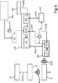
Im Vergleich zu Variante 3 erfolgt die Aktivierung beziehungsweise der Befehl für einen Zustandswechsel der Sendeeinrichtung über ein Aktivierungsmuster bzw. Signalmuster. Dieses wird etwa durch Betätigung eines Lichtschalters initiiert (an, aus, an, aus, ...). Die Basis bilden wiederum unterschiedliche Spannungspegel zwischen der externen und internen Energieversorgung (intern: Versorgung über Energiezwischenspeicher).In comparison to variant 3, the activation or the command for a state change of the transmitting device takes place via an activation pattern or signal pattern. This is going through Operation of a light switch initiated (on, off, on, off, ...). The basis is again formed by different voltage levels between the external and internal energy supply (internally: supply via energy buffer).
Variante 5:Variant 5:
Neben dem Energiezwischenspeicher wird eine zusätzliche Batterie bei der Herstellung verbaut. Die Batterie versorgt den Energiezwischenspeicher während Lagerung und Transport mit Energie. Sobald die Lampe bzw. das Leuchtmittel mit Strom versorgt wird, wird von der Batterie auf normalen Akkubetrieb umgeschaltet.In addition to the energy buffer, an additional battery is installed during production. The battery powers the energy buffer during storage and transportation. As soon as the lamp or the light source is supplied with power, the battery is switched to normal battery operation.
Variante 6:Variant 6:
Die Energieversorgung oder ein spezieller Kontakt der Sendeeinrichtung ist während des Transports durch ein Isolierelement bzw. einen „Zipper“ (z.B. Papier, nicht leitende Folie) getrennt. Bei der Installation der Leuchte wird das Isolationselement herausgezogen und somit der Beacon aktiviert beziehungsweise aus dem Energiesparmodus geweckt.The power supply or a special contact of the transmitter is separated during transport by an insulating member or "zipper" (e.g., paper, non-conductive foil). When installing the lamp, the insulation element is pulled out and thus the beacon is activated or awakened from the energy-saving mode.
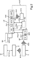
Im Zusammenhang mit
Die übrigen Komponenten der Beleuchtungsvorrichtung beziehungsweise des Gesamtsystems sind wie folgt angeordnet bzw. verschaltet. Die Leuchteinrichtung besitzt neben dem Empfänger
Ein Energiezwischenspeicher
Die Sendeeinrichtung
Von der Sendeeinrichtung
In dem vorliegenden Beispiel ist die Leuchteinrichtung
Hinsichtlich der übrigen Komponenten und Verbindungen der Beleuchtungsvorrichtung beziehungsweise des Systems von
In einem weiteren Ausführungsbeispiel gemäß
Hinsichtlich der übrigen Komponenten und Verbindungen wird wiederum auf die Beschreibung dieser Komponenten im Zusammenhang mit dem Beispiel von
In vorteilhafter Weise gewährleisten die erfindungsgemäßen Systeme, dass ein fehlerbehafteter Austausch von Batterien bei Beleuchtungsmitteln mit Sendeeinrichtungen größtenteils vermieden werden kann. Insbesondere kann auch eine Tiefenentladung während der Logistikprozesse unterbunden werden.Advantageously, the systems according to the invention ensure that a faulty replacement of batteries in lighting means with transmitting devices can be largely avoided. In particular, a depth discharge during the logistics processes can be prevented.
BezugszeichenlisteLIST OF REFERENCE NUMBERS
- AMAT THE
- Aktivierungsmusteractivation patterns
- B1B1
- BeaconBeacon
- B2B2
- BeaconBeacon
- BEBE
- Beleuchtungseinrichtunglighting device
- DSDS
- DatenschnittstelleData Interface
- DTDT
- DatenübertragungssystemData transfer system
- DVDV
- DatenverarbeitungseinheitData processing unit
- Ee
- Endgerätterminal
- ECGECG
- elektronisches Vorschaltgerätelectronic ballast
- EK1-9EK1-9
- EnergieübertragungskanalEnergy transmission channel
- EMPEMP
- Empfängerreceiver
- ESIT
- EnergieschnittstelltePower interface Imagined
- EZEZ
- EnergiezwischenspeicherStorage of energy
- IEIE
- Infrastruktureinrichtunginfrastructure facility
- IVIV
- InformationsverarbeitungseinheitInformation processing unit
- ISIS
- Infrastruktur für DiensteInfrastructure for services
- KV1-11KV1-11
- Kommunikationsverbindungcommunication link
- LMLM
- LeuchtmittelLamp
- LPLP
- LED-PlatineLED board
- LSLS
- Lichtschalterlight switch
- MM
- Modulmodule
- NVNV
- externe Netzversorgungexternal mains supply
- PV1PV1
- physikalische Verbindungphysical connection
- PV2PV2
- physikalische Verbindungphysical connection
- RR
- Routerrouter
- SESE
- Sendeeinrichtungtransmitting device
- STESTE
- steuerndes Endgerätcontrolling terminal
Claims (20)
Priority Applications (4)
| Application Number | Priority Date | Filing Date | Title |
|---|---|---|---|
| DE102016121663.1A DE102016121663A1 (en) | 2016-11-11 | 2016-11-11 | Activating a transmitting device of a lighting device |
| PCT/EP2017/071634 WO2018086779A1 (en) | 2016-11-11 | 2017-08-29 | Activation of a transmitting apparatus of an illuminating device |
| CN201780069851.3A CN109923431B (en) | 2016-11-11 | 2017-08-29 | Activation of a transmitting device of a lighting device |
| US16/348,039 US11307281B2 (en) | 2016-11-11 | 2017-08-29 | Activation of a transmitting device of a lighting device |
Applications Claiming Priority (1)
| Application Number | Priority Date | Filing Date | Title |
|---|---|---|---|
| DE102016121663.1A DE102016121663A1 (en) | 2016-11-11 | 2016-11-11 | Activating a transmitting device of a lighting device |
Publications (1)
| Publication Number | Publication Date |
|---|---|
| DE102016121663A1 true DE102016121663A1 (en) | 2018-05-17 |
Family
ID=59738362
Family Applications (1)
| Application Number | Title | Priority Date | Filing Date |
|---|---|---|---|
| DE102016121663.1A Pending DE102016121663A1 (en) | 2016-11-11 | 2016-11-11 | Activating a transmitting device of a lighting device |
Country Status (4)
| Country | Link |
|---|---|
| US (1) | US11307281B2 (en) |
| CN (1) | CN109923431B (en) |
| DE (1) | DE102016121663A1 (en) |
| WO (1) | WO2018086779A1 (en) |
Families Citing this family (8)
| Publication number | Priority date | Publication date | Assignee | Title |
|---|---|---|---|---|
| US10497161B1 (en) | 2018-06-08 | 2019-12-03 | Curious Company, LLC | Information display by overlay on an object |
| US10650600B2 (en) | 2018-07-10 | 2020-05-12 | Curious Company, LLC | Virtual path display |
| US10818088B2 (en) | 2018-07-10 | 2020-10-27 | Curious Company, LLC | Virtual barrier objects |
| US10902678B2 (en) | 2018-09-06 | 2021-01-26 | Curious Company, LLC | Display of hidden information |
| US11055913B2 (en) | 2018-12-04 | 2021-07-06 | Curious Company, LLC | Directional instructions in an hybrid reality system |
| US10970935B2 (en) | 2018-12-21 | 2021-04-06 | Curious Company, LLC | Body pose message system |
| US10872584B2 (en) * | 2019-03-14 | 2020-12-22 | Curious Company, LLC | Providing positional information using beacon devices |
| DE102021124749A1 (en) * | 2021-09-24 | 2023-03-30 | Zumtobel Lighting Gmbh | Swarm-controlled lighting system with configurable transmission power |
Citations (5)
| Publication number | Priority date | Publication date | Assignee | Title |
|---|---|---|---|---|
| EP0174913A2 (en) * | 1984-09-12 | 1986-03-19 | Andi Steiner | Packaging for an object and utilization of that package |
| DE19639188A1 (en) * | 1996-09-24 | 1998-04-02 | Siemens Ag | Base station for mobile communications system |
| US20150237706A1 (en) * | 2012-09-12 | 2015-08-20 | Ariel-University Research And Development Company Ltd. | Light fixture connectable device useful for establishing a network infrastructure |
| US20160073479A1 (en) * | 2013-05-01 | 2016-03-10 | BeON HOME INC. | Modular illumination device and associated systems and methods |
| US20160127875A1 (en) * | 2014-11-05 | 2016-05-05 | Beco, Inc. | Systems, methods and apparatus for light enabled indoor positioning and reporting |
Family Cites Families (16)
| Publication number | Priority date | Publication date | Assignee | Title |
|---|---|---|---|---|
| US6529164B1 (en) * | 2000-03-31 | 2003-03-04 | Ge Medical Systems Information Technologies, Inc. | Object location monitoring within buildings |
| ATE378752T1 (en) * | 2005-01-21 | 2007-11-15 | Research In Motion Ltd | ENERGY SAVING AND TREATING BROADCAST MESSAGES LIKE SIMPLE MESSAGES IN A WIFI |
| US7812543B2 (en) * | 2006-11-15 | 2010-10-12 | Budike Jr Lothar E S | Modular wireless lighting control system using a common ballast control interface |
| DE202008015784U1 (en) * | 2008-11-28 | 2009-03-12 | Woelke Industrieelektronik Gmbh | Uninterruptible power supply device |
| US9345115B2 (en) * | 2009-09-05 | 2016-05-17 | Enlighted, Inc. | Distributed light fixture beacon transmission |
| US9585228B2 (en) * | 2012-11-30 | 2017-02-28 | Enlighted, Inc. | Associating information with an asset or a physical space |
| CN105706534A (en) * | 2013-03-06 | 2016-06-22 | 维文公司 | Wirelessly Controlled Light Sources |
| EP3053414B1 (en) * | 2013-10-03 | 2018-08-15 | Casambi Technologies OY | Intelligent lighting control |
| CN106662322A (en) * | 2014-08-01 | 2017-05-10 | 飞利浦灯具控股公司 | Luminaire with radio module |
| JP6452030B2 (en) * | 2014-09-09 | 2019-01-16 | パナソニックIpマネジメント株式会社 | Lighting equipment and positioning system |
| US10849205B2 (en) * | 2015-10-14 | 2020-11-24 | Current Lighting Solutions, Llc | Luminaire having a beacon and a directional antenna |
| DE102015119626A1 (en) * | 2015-11-13 | 2017-05-18 | Osram Gmbh | Illuminating device with directional radio signal for position identification |
| DE102016107154A1 (en) * | 2016-04-18 | 2017-10-19 | Osram Gmbh | Lighting device with transmission of operating data |
| DE102016125636A1 (en) * | 2016-12-23 | 2018-06-28 | Osram Gmbh | Operation of a transmitting device of a lighting device having a lighting device |
| DE102016125631A1 (en) * | 2016-12-23 | 2018-06-28 | Osram Gmbh | Install or change an executable computer program in a lighting system |
| US10390183B2 (en) * | 2017-02-24 | 2019-08-20 | Lsi Industries, Inc. | Light fixture positioning system that transmits beacon signals having different spatial resolutions |
-
2016
- 2016-11-11 DE DE102016121663.1A patent/DE102016121663A1/en active Pending
-
2017
- 2017-08-29 CN CN201780069851.3A patent/CN109923431B/en active Active
- 2017-08-29 WO PCT/EP2017/071634 patent/WO2018086779A1/en not_active Ceased
- 2017-08-29 US US16/348,039 patent/US11307281B2/en active Active
Patent Citations (5)
| Publication number | Priority date | Publication date | Assignee | Title |
|---|---|---|---|---|
| EP0174913A2 (en) * | 1984-09-12 | 1986-03-19 | Andi Steiner | Packaging for an object and utilization of that package |
| DE19639188A1 (en) * | 1996-09-24 | 1998-04-02 | Siemens Ag | Base station for mobile communications system |
| US20150237706A1 (en) * | 2012-09-12 | 2015-08-20 | Ariel-University Research And Development Company Ltd. | Light fixture connectable device useful for establishing a network infrastructure |
| US20160073479A1 (en) * | 2013-05-01 | 2016-03-10 | BeON HOME INC. | Modular illumination device and associated systems and methods |
| US20160127875A1 (en) * | 2014-11-05 | 2016-05-05 | Beco, Inc. | Systems, methods and apparatus for light enabled indoor positioning and reporting |
Also Published As
| Publication number | Publication date |
|---|---|
| CN109923431B (en) | 2023-06-27 |
| US11307281B2 (en) | 2022-04-19 |
| CN109923431A (en) | 2019-06-21 |
| US20190271755A1 (en) | 2019-09-05 |
| WO2018086779A1 (en) | 2018-05-17 |
Similar Documents
| Publication | Publication Date | Title |
|---|---|---|
| DE102016121663A1 (en) | Activating a transmitting device of a lighting device | |
| EP3560297B1 (en) | Installing or changing an executable computer program in an illumination system | |
| DE102004055933A1 (en) | Method for assigning short addresses in lighting installations | |
| EP2983145A1 (en) | Alarm socket and connection base for detachable attachment of a danger warning system, each with a radio device for emitting position data of the installation location of the alarm socket or the connection base and/or a reference to this position data | |
| EP3339873B1 (en) | Operation of a transmission device of a lighting device having a light assembly | |
| DE102017113565A1 (en) | CONTROL DEVICE FOR LUMINAIRES, LIGHTING CONTROL SYSTEM AND METHOD FOR CONTROLLING ENERGY CONSUMPTION | |
| EP3375257B1 (en) | Lighting device and method for supplying a wireless transmission module | |
| EP3427548B1 (en) | Lighting system featuring automatic beacon configuration | |
| DE102015211149B4 (en) | Intelligent additional modules for luminaires | |
| DE102016121977A1 (en) | Create an installation layout of a lighting system | |
| WO2017153147A1 (en) | Lighting apparatus with current limiting for communication device | |
| EP3559923B1 (en) | Controlling at least one controllable device arranged in a region predefined by a lighting device | |
| EP3446553B1 (en) | Lighting device comprising the transmission of operating data | |
| WO2018114065A1 (en) | Activating and deactivating the reception unit of a lighting device | |
| WO2018086780A1 (en) | Lighting system with analysis signal evaluation | |
| DE102016104486A1 (en) | Illumination system with signaling of a communication connection | |
| DE212014000113U1 (en) | Illumination system for the control of illuminant operating devices | |
| DE112012004148B4 (en) | Method and lighting system for controlling at least two independently controllable light-emitting diodes | |
| WO2020187616A1 (en) | Address allocation and configuration of components of a lighting system using light signals | |
| EP3627973B1 (en) | Electric consumption module and method for operating an electric consumption module | |
| DE102015119629A1 (en) | Location of an object with transmitter | |
| EP2892304B1 (en) | Device assembly | |
| WO2017153145A1 (en) | Lighting apparatus comprising a communication device |
Legal Events
| Date | Code | Title | Description |
|---|---|---|---|
| R163 | Identified publications notified | ||
| R079 | Amendment of ipc main class |
Free format text: PREVIOUS MAIN CLASS: H05B0037000000 Ipc: H05B0047000000 |
|
| R012 | Request for examination validly filed | ||
| R082 | Change of representative |
Representative=s name: SCHEELE JAEGER WETZEL PATENTANWAELTE PARTG MBB, DE Representative=s name: IMPULS LEGAL PARTG MBB, DE Representative=s name: SCHEELE JAEGER PATENTANWAELTE PARTG MBB, DE |
|
| R082 | Change of representative |
Representative=s name: IMPULS LEGAL PARTG MBB, DE |