DE102015114808B4 - Reduction of steering wheel jerking during automatic parking/exit - Google Patents
Reduction of steering wheel jerking during automatic parking/exit Download PDFInfo
- Publication number
- DE102015114808B4 DE102015114808B4 DE102015114808.0A DE102015114808A DE102015114808B4 DE 102015114808 B4 DE102015114808 B4 DE 102015114808B4 DE 102015114808 A DE102015114808 A DE 102015114808A DE 102015114808 B4 DE102015114808 B4 DE 102015114808B4
- Authority
- DE
- Germany
- Prior art keywords
- torque
- power steering
- steering
- steering motor
- steering wheel
- Prior art date
- Legal status (The legal status is an assumption and is not a legal conclusion. Google has not performed a legal analysis and makes no representation as to the accuracy of the status listed.)
- Active
Links
Images
Classifications
-
- B—PERFORMING OPERATIONS; TRANSPORTING
- B62—LAND VEHICLES FOR TRAVELLING OTHERWISE THAN ON RAILS
- B62D—MOTOR VEHICLES; TRAILERS
- B62D15/00—Steering not otherwise provided for
- B62D15/02—Steering position indicators ; Steering position determination; Steering aids
- B62D15/027—Parking aids, e.g. instruction means
- B62D15/0285—Parking performed automatically
-
- B—PERFORMING OPERATIONS; TRANSPORTING
- B62—LAND VEHICLES FOR TRAVELLING OTHERWISE THAN ON RAILS
- B62D—MOTOR VEHICLES; TRAILERS
- B62D1/00—Steering controls, i.e. means for initiating a change of direction of the vehicle
- B62D1/24—Steering controls, i.e. means for initiating a change of direction of the vehicle not vehicle-mounted
- B62D1/28—Steering controls, i.e. means for initiating a change of direction of the vehicle not vehicle-mounted non-mechanical, e.g. following a line or other known markers
- B62D1/286—Systems for interrupting non-mechanical steering due to driver intervention
-
- B—PERFORMING OPERATIONS; TRANSPORTING
- B62—LAND VEHICLES FOR TRAVELLING OTHERWISE THAN ON RAILS
- B62D—MOTOR VEHICLES; TRAILERS
- B62D5/00—Power-assisted or power-driven steering
- B62D5/04—Power-assisted or power-driven steering electrical, e.g. using an electric servo-motor connected to, or forming part of, the steering gear
- B62D5/0457—Power-assisted or power-driven steering electrical, e.g. using an electric servo-motor connected to, or forming part of, the steering gear characterised by control features of the drive means as such
- B62D5/046—Controlling the motor
- B62D5/0463—Controlling the motor calculating assisting torque from the motor based on driver input
-
- B—PERFORMING OPERATIONS; TRANSPORTING
- B62—LAND VEHICLES FOR TRAVELLING OTHERWISE THAN ON RAILS
- B62D—MOTOR VEHICLES; TRAILERS
- B62D6/00—Arrangements for automatically controlling steering depending on driving conditions sensed and responded to, e.g. control circuits
-
- B—PERFORMING OPERATIONS; TRANSPORTING
- B62—LAND VEHICLES FOR TRAVELLING OTHERWISE THAN ON RAILS
- B62D—MOTOR VEHICLES; TRAILERS
- B62D6/00—Arrangements for automatically controlling steering depending on driving conditions sensed and responded to, e.g. control circuits
- B62D6/007—Arrangements for automatically controlling steering depending on driving conditions sensed and responded to, e.g. control circuits adjustable by the driver, e.g. sport mode
Landscapes
- Engineering & Computer Science (AREA)
- Chemical & Material Sciences (AREA)
- Combustion & Propulsion (AREA)
- Transportation (AREA)
- Mechanical Engineering (AREA)
- Steering Control In Accordance With Driving Conditions (AREA)
Abstract
Automatisches Ein-/Ausparksystem für ein Fahrzeug (10), umfassend:
einen Servolenkmotor (26), der derart ausgelegt ist, dass er ein Servolenkmotormoment (70) für das Fahrzeug (10) bereitstellt,
einen Lenkradmomentsensor (36), der derart ausgelegt ist, dass er ein an ein Lenkrad (22) von einem Bediener angelegtes Drehmoment erfasst, und
eine Steuerung (30), die mit dem Lenkradmomentsensor (36) gekoppelt und derart programmiert ist, dass sie als Reaktion darauf, dass ein Drehmoment an das Lenkrad (22) während eines automatischen Ein-/Ausparkvorgangs angelegt wird, das Servolenkmotormoment (70) rampenartig herabsetzt;
dadurch gekennzeichnet, dass die Steuerung (30) ferner programmiert ist, den Betrieb des Servolenkmotors (26) derart zurückzusetzen, dass er ein Servolenkmotormoment (70) auf der Grundlage einer Fahrereingabe an das Lenkrad (22) zum Lenken des Fahrzeugs (10) bereitstellt; und
die Steuerung (30) ferner programmiert ist, beim Erhalt eines Hinweises darauf, dass ein Fahrer eine Beschleunigung eingeleitet hat, den Betrieb des Servolenkmotors (26) derart zurückzusetzen, dass er ein Servolenkmotormoment (70) auf der Grundlage einer Fahrereingabe an das Lenkrad (22) zum Lenken des Fahrzeugs (10) bereitstellt.

a power steering motor (26) configured to provide a power steering motor torque (70) to the vehicle (10),
a steering wheel torque sensor (36) configured to detect a torque applied to a steering wheel (22) by an operator, and
a controller (30) coupled to the steering wheel torque sensor (36) and programmed to ramp down the power steering motor torque (70) in response to torque being applied to the steering wheel (22) during an automatic parking/unparking operation;
characterized in that the controller (30) is further programmed to reset the operation of the power steering motor (26) to provide a power steering motor torque (70) based on a driver input to the steering wheel (22) for steering the vehicle (10); and
the controller (30) is further programmed, upon receiving an indication that a driver has initiated acceleration, to reset operation of the power steering motor (26) to provide a power steering motor torque (70) based on a driver input to the steering wheel (22) for steering the vehicle (10).
Description
TECHNISCHES GEBIETTECHNICAL FIELD
Die Erfindung betrifft ein automatisches Ein-/Ausparksystem für ein Fahrzeug nach dem Oberbegriff des Anspruchs 1, ein Reifen-Windup-Ausgleichssystem für ein Fahrzeug nachh dem Oberbegriff des Anspruchs 5 sowie ein Fahrzeug nach dem Oberbegriff des Anspruchs 11. Die Offenbarung betrifft insbesondere Fahrzeuglenksysteme mit Kraftunterstützung und insbesondere die Milderung der Auswirkungen von Reifen-Windup auf ein Lenksystem während automatischer Ein-/Ausparkvorgänge.The invention relates to an automatic parking/exit system for a vehicle according to the preamble of claim 1, a tire windup compensation system for a vehicle according to the preamble of claim 5 and a vehicle according to the preamble of claim 11. The disclosure relates in particular to power assisted vehicle steering systems and in particular to mitigating the effects of tire windup on a steering system during automatic parking/exit operations.
HINTERGRUNDBACKGROUND
Ein Reifen wird an einem Fahrzeugrad montiert, um Traktion zwischen dem Fahrzeug und der Fahrbahn sowie ein nachgiebiges Polster zum Auffangen von Stößen bereitzustellen. Die meisten Reifen sind aufblasbare pneumatische Strukturen, die einen ringförmigen Körper aus Korden und Drähten umfassen, der mit Gummi umhüllt und allgemein mit Druckluft befüllt ist, um ein aufblasbares Polster zu bilden.A tire is mounted on a vehicle wheel to provide traction between the vehicle and the road surface, as well as a compliant cushion to absorb shock. Most tires are inflatable pneumatic structures consisting of a ring-shaped body made of cords and wires, covered with rubber, and generally filled with compressed air to form an inflatable cushion.
Aufgrund der Konstruktion eines Reifens kann ein Reifen als eine Feder wirken und potentielle Energie speichern, wenn das Rad gedreht wird. Diese federartige Wirkung wird durch die Reibung der Fahrbahnoberfläche verursacht, die sich dem Drehen des zu einer Bodenaufstandsfläche des Reifens benachbarten Abschnitts des Reifens widersetzt. Wenn das Rad gedreht wird, drehen sich in der Nähe des Rads befindliche Abschnitte des Reifens mit dem Rad, während in der Nähe der Bodenaufstandsfläche befindliche Abschnitte des Reifens der Drehbewegung widerstehen können. Folglich kann sich ein Abschnitt des Reifens zwischen dem Rad und der Aufstandsfläche elastisch verformen. Die elastische Verformung des Reifens, oder genauer der Wunsch des Reifens, in eine nicht verformte Form zurückzukehren, liefert die potenzielle Energie, die als Reifen-Windup bezeichnet wird.Due to the design of a tire, a tire can act as a spring, storing potential energy when the wheel is rotated. This spring-like action is caused by the friction of the road surface resisting the rotation of the portion of the tire adjacent to a tire contact patch. When the wheel is rotated, portions of the tire near the wheel rotate with the wheel, while portions of the tire near the ground contact patch can resist the rotational motion. Consequently, a portion of the tire between the wheel and the contact patch can deform elastically. The elastic deformation of the tire, or more accurately, the tire's desire to return to an undeformed shape, provides the potential energy known as tire windup.
Automatisches Ein-/Ausparken, das auch als Active Park Assist (aktive Einparkhilfe) bekannt ist, ist ein unabhängiges Fahrzeugrangiersystem, das ein Fahrzeug in eine oder aus einer Parklücke bewegt (Einparken und Ausparken). Parklücken können parallele, senkrechte oder schräge Parklücken umfassen. Das Ziel des automatischen Ein-/Ausparksystems ist es, den Komfort und die Sicherheit des Fahrens in beschränkten Umgebungen, in denen viel Aufmerksamkeit und Erfahrung zum Lenken des Fahrzeugs erforderlich ist, zu verbessern. Das Ein-/Ausparkmanöver wird mithilfe einer koordinierten Steuerung des Lenkwinkels und der Geschwindigkeit erreicht, die die tatsächliche Situation in der Umgebung berücksichtigt, um eine kollisionsfreie Bewegung innerhalb des verfügbaren Raums zu gewährleisten.Automatic parking, also known as Active Park Assist, is an independent vehicle maneuvering system that moves a vehicle into or out of a parking space (parking and reversing). Parking spaces can include parallel, perpendicular, or angled parking spaces. The goal of the automatic parking system is to improve the comfort and safety of driving in confined spaces where considerable attention and skill are required to steer the vehicle. The parking maneuver is achieved using coordinated control of the steering angle and speed, taking into account the actual situation in the surroundings, to ensure collision-free movement within the available space.
Ein automatisches Ein-/Ausparksystem gemäß dem Oberbegriff von Anspruch 1 ist aus der
Ein Reifen-Windup kann deutlicher hervortreten, wenn Reifen an einem Fahrzeug gedreht werden, während es sich langsam oder gar nicht bewegt, wie z.B. wenn das Fahrzeug einen automatischen Ein-/Ausparkvorgang ausführt. Während oder beim Beenden eines automatischen Ein-/Ausparkvorgangs kann das Windup des Reifens verursachen, dass der Lenkradwinkel zu einem anderen Winkel zuckt, wenn der Servolenkmotor aufhört, Drehmoment an das Lenksystem bereitzustellen. Dies kann auch als ein Lenkradruck bezeichnet werden. Ein automatischer Ein-/Ausparkvorgang kann dadurch gestoppt werden, dass ein Bediener nach dem Lenkrad greift, und falls der Reifen ein Windup aufweist, wenn der Servolenkmotor das an das Lenksystem gelieferte Drehmoment abbaut, kann das Lenkrad unerwünschterweise zu einem neuen Winkel in den Händen des Bedieners zucken.Tire windup can be more noticeable when tires on a vehicle are rotated while it is moving slowly or not at all, such as when the vehicle is performing an automatic parking maneuver. During or upon completion of an automatic parking maneuver, tire windup can cause the steering wheel angle to jerk to a different angle when the power steering motor stops providing torque to the steering system. This may also be referred to as steering wheel jerk. An automatic parking maneuver can be stopped by an operator reaching for the steering wheel, and if the tire winds up when the power steering motor releases the torque supplied to the steering system, the steering wheel may undesirably jerk to a new angle in the operator's hands.
KURZDARSTELLUNGSUMMARY
Die Lösung vorliegend genannten Problems erfolgt durch ein automatisches Ein-/Ausparksystem mit den Merkmalen des Anspruchs 1, durch ein Reifen-Windup-Ausgleichssystem mit den Merkmalen des Anspruchs 5 sowie durch ein Fahrzeug mit den Merkmalen des Anspruchs 11. Vorteilhafte Weiterbildungen ergeben sich aus den Unteransprüchen und der nachfolgenden Beschreibung.The solution to the problem mentioned here is provided by an automatic parking/exit system having the features of claim 1, by a tire windup compensation system having the features of claim 5 and by a vehicle having the features of claim 11. Advantageous further developments emerge from the subclaims and the following description.
Ein Aspekt dieser Offenbarung ist auf ein automatisches Ein-/Ausparksystem für ein Fahrzeug gerichtet, das einen Servolenkmotor, einen Lenkradmomentsensor und eine mit dem Lenkradmomentsensor gekoppelte Steuerung aufweist. Der Servolenkmotor ist derart ausgelegt, dass er ein Servolenkmotormoment für das Fahrzeug bereitstellt. Der Lenkradmomentsensor ist derart ausgelegt, dass er das an ein Lenkrad von einem Bediener angelegte Drehmoment erfasst. Die Steuerung ist derart programmiert, dass sie als Reaktion darauf, dass ein Drehmoment an das Lenkrad während eines automatischen Ein-/Ausparkvorgangs angelegt wird, das Servolenkmotormoment des Servolenkmotors rampenartig herabsetzt.One aspect of this disclosure is directed to an automatic parking/exit system for a vehicle having a power steering motor, a steering wheel torque sensor, and a controller coupled to the steering wheel torque sensor. The power steering motor is configured to Provides power steering motor torque to the vehicle. The steering wheel torque sensor is configured to detect the torque applied to a steering wheel by an operator. The controller is programmed to ramp down the power steering motor torque in response to torque being applied to the steering wheel during an automatic parking maneuver.
Die Steuerung kann derart programmiert sein, dass sie das Drehmoment des Servolenkmotors über eine eingestellte Zeitdauer rampenartig herabsetzt. Die Steuerung ist außerdem derart programmiert, dass sie den Betrieb des Servolenkmotors zurücksetzt, um ein Servolenkmotormoment auf der Grundlage einer Fahrereingabe an das Lenkrad zum Lenken des Fahrzeugs bereitzustellen. Die Steuerung ist außerdem derart programmiert, dass sie beim Erhalten eines Hinweises auf eine vom Fahrer eingeleitete Beschleunigung den Betrieb des Servolenkmotors zurücksetzt, um ein Servolenkmotormoment auf der Grundlage einer Fahrereingabe an das Lenkrad zum Lenken des Fahrzeugs bereitzustellen.The controller may be programmed to ramp down the torque of the power steering motor over a set period of time. The controller is also programmed to reset the operation of the power steering motor to provide power steering motor torque based on a driver input to the steering wheel for steering the vehicle. The controller is also programmed to reset the operation of the power steering motor upon receiving an indication of driver-initiated acceleration to provide power steering motor torque based on a driver input to the steering wheel for steering the vehicle.
Das an das Lenkrad während des automatischen Ein-/Ausparkvorgangs angelegte Drehmoment, das die Reaktion der Steuerung auslöst, kann bei oder über einem Drehmomentschwellenwert liegen. Der automatische Ein-/Ausparkvorgang kann ein Ausparkvorgang sein.The torque applied to the steering wheel during the automatic parking maneuver, which triggers the control response, may be at or above a torque threshold. The automatic parking maneuver may be a parking exit maneuver.
Ein anderer Aspekt dieser Offenbarung richtet sich auf ein Reifen-Windup-Ausgleichssystem für ein Fahrzeug. Das System weist einen Servolenkmotor auf, der derart ausgelegt ist, dass er ein Servolenkmotormoment an Vorderräder eines Fahrzeugs liefert. Das System weist einen Lenkradmomentsensor auf. Das System weist eine mit dem Servolenkmotor und dem Lenkradmomentsensor gekoppelte Steuerung auf. Die Steuerung ist derart programmiert, dass sie als Reaktion auf ein Beenden eines Ausparkvorgangs das Servolenkmotormoment des Servolenkmotors modifiziert, so dass es im Wesentlichen dem Lenkradmoment entspricht, um ein Reifen-Windup auszugleichen.Another aspect of this disclosure is directed to a tire windup compensation system for a vehicle. The system includes a power steering motor configured to provide power steering motor torque to front wheels of a vehicle. The system includes a steering wheel torque sensor. The system includes a controller coupled to the power steering motor and the steering wheel torque sensor. The controller is programmed to modify the power steering motor torque of the power steering motor to substantially equal the steering wheel torque in response to completion of a parking maneuver to compensate for tire windup.
Die Steuerung kann ferner derart programmiert sein, dass sie das Drehmoment des Servolenkmotors von dem Lenkradmoment auf null reduziert. Die Steuerung kann ferner derart programmiert sein, dass sie das Drehmoment des Servolenkmotors mit variierenden Raten über eine vorgegebene Zeitdauer reduziert. Die variierenden Raten weisen eine Anfangsrate und eine Endrate auf und die Anfangsrate kann eine schnellere Drehmomentreduzierung aufweisen als die Endrate. Die Steuerung kann ferner derart programmiert sein, dass sie das Drehmoment des Servolenkmotors mit einer vorgegebenen konstanten Rate reduziert. Die Steuerung kann ferner auch derart programmiert sein, dass sie das Drehmoment des Servolenkmotors aufrechterhält, bis sie einen Hinweis auf eine Fahrzeugbeschleunigung erhält.The controller may be further programmed to reduce the torque of the power steering motor from the steering wheel torque to zero. The controller may be further programmed to reduce the torque of the power steering motor at varying rates over a predetermined period of time. The varying rates include an initial rate and a final rate, and the initial rate may have a faster torque reduction than the final rate. The controller may be further programmed to reduce the torque of the power steering motor at a predetermined constant rate. The controller may also be further programmed to maintain the torque of the power steering motor until it receives an indication of vehicle acceleration.
Ein weiterer Aspekt dieser Offenbarung richtet sich auf ein Fahrzeug, aufweisend: ein Paar drehbare Räder, ein Lenksystem, das ein Lenkgestänge, das ein Lenkrad mit dem Paar drehbare Räder verbindet, aufweist, und eine Steuerung, die zum Steuern des Lenksystems zum Durchführen eines automatischen Ein-/Ausparkmanövers programmiert ist. Das Paar drehbare Räder weist Reifen auf, die um die Räder angeordnet sind. Das Lenksystem weist einen Lenkradmomentsensor auf, der zum Überwachen des Lenkradmoments ausgelegt ist. Das Lenksystem weist einen mit dem Lenkgestänge gekoppelten Servolenkmotor auf, der derart ausgelegt ist, dass er ein Drehmoment an das Lenksystem liefert, so dass das Paar drehbare Räder gedreht wird. Das Lenksystem weist außerdem einen Servolenkmotormomentsensor auf, der zum Überwachen des Drehmoments des Servolenkmotors ausgelegt ist.Another aspect of this disclosure is directed to a vehicle comprising: a pair of rotatable wheels, a steering system comprising a steering linkage connecting a steering wheel to the pair of rotatable wheels, and a controller programmed to control the steering system to perform an automatic parking maneuver. The pair of rotatable wheels includes tires disposed around the wheels. The steering system includes a steering wheel torque sensor configured to monitor steering wheel torque. The steering system includes a power steering motor coupled to the steering linkage and configured to provide torque to the steering system to rotate the pair of rotatable wheels. The steering system also includes a power steering motor torque sensor configured to monitor torque of the power steering motor.
Die Steuerung gemäß diesem Aspekt ist derart programmiert, dass sie, wenn sie erkennt, dass während eines automatischen Ein-/Ausparkmanövers ein Fahrer ein Drehmoment an das Lenkrad bereitstellt, das automatische Ein-/Ausparkmanöver stoppt und den Servolenkmotor derart steuert, dass er ein auf das Lenksystem wirkendes Drehmoment aufrechterhält, um ein während des automatischen Ein-/Ausparkmanövers angesammeltes Reifen-Windup auszugleichen.The controller according to this aspect is programmed such that, when it detects that a driver is providing torque to the steering wheel during an automatic parking maneuver, it stops the automatic parking maneuver and controls the power steering motor to maintain torque applied to the steering system to compensate for tire windup accumulated during the automatic parking maneuver.
Bei diesem Aspekt kann das automatische Ein-/Ausparkmanöver ein Ausparkvorgang sein. Die Steuerung kann ferner derart programmiert sein, dass sie ein auf das Lenksystem wirkendes Drehmoment aufrechterhält, bis das Fahrzeug beschleunigt. Die Steuerung kann außerdem derart programmiert sein, dass sie das an das Lenksystem durch den Servolenkmotor gelieferte Drehmoment mit einer kontrollierten Rate rampenartig verringert, um eine Zuckung des Lenkrads zu verhindern.In this aspect, the automatic parking maneuver may be a parking maneuver. The controller may be further programmed to maintain torque applied to the steering system until the vehicle accelerates. The controller may also be programmed to ramp down the torque delivered to the steering system by the power steering motor at a controlled rate to prevent steering wheel jerk.
Die vorstehenden Aspekte dieser Offenbarung und andere Aspekte werden nachstehend unter Bezugnahme auf die beigefügten Zeichnungen ausführlicher erläutert.The above aspects of this disclosure and other aspects are explained in more detail below with reference to the accompanying drawings.
KURZE BESCHREIBUNG DER ZEICHNUNGENBRIEF DESCRIPTION OF THE DRAWINGS
-
1 ist eine Diagrammansicht eines Fahrzeuglenksystems.1 is a diagrammatic view of a vehicle steering system. -
2 ist eine Querschnittsansicht eines Rads und eines Reifens auf einer Fahrbahnoberfläche.2 is a cross-sectional view of a wheel and tire on a road surface. -
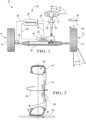
3 ist ein Graph eines nicht erfindungsgemäßen Beispiels für eine Reifen-Windup-Steuerstrategie.3 is a graph of an example tire windup control strategy not according to the invention. -
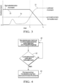
4 ist ein Ablaufdiagramm eines Beispiels für eine Reifen-Windup-Steuerstrategie.4 is a flowchart of an example tire windup control strategy.
AUSFÜHRLICHE BESCHREIBUNGDETAILED DESCRIPTION
Die dargestellten Ausführungsformen werden unter Bezugnahme auf die Zeichnungen offenbart. Jedoch versteht es sich, dass die offenbarten Ausführungsformen lediglich Beispiele sein sollen, die in mehreren und alternativen Formen ausgeführt sein können. Die Figuren sind nicht notwendigerweise maßstabsgetreu und einige Merkmale können vergrößert oder verkleinert sein, um Einzelheiten bestimmter Komponenten darzustellen. Die offenbarten konkreten strukturellen und funktionellen Einzelheiten sind nicht als Beschränkung auszulegen, sondern als eine repräsentative Grundlage, um einen Fachmann zu lehren, wie die offenbarten Konzepte eingesetzt werden können.The illustrated embodiments are disclosed with reference to the drawings. However, it should be understood that the disclosed embodiments are merely examples that may be embodied in multiple and alternative forms. The figures are not necessarily to scale, and some features may be exaggerated or reduced to show details of particular components. The specific structural and functional details disclosed are not to be interpreted as limiting, but rather as a representative basis for teaching one skilled in the art how to utilize the disclosed concepts.
Die Winkelposition, in der das Laufrad 12 im Wesentlichen geradeaus ausgerichtet ist, wird als die Nullposition, oder als eine solche Position, in der α annäherungsweise null Grad beträgt, bezeichnet. Eine Vor-/Nachspur kann leichte Abweichungen der Winkeldrehung von der echten Nullposition bedingen, aber die Nullposition soll die Laufradposition sein, die es dem Fahrzeug ermöglicht, sich in eine im Wesentlichen geradeaus gerichtete Richtung zu bewegen. Der Drehwinkel α wird dann, von der Nullposition ausgehend, entweder mit einem positiven, einem negativen oder einem Absolutwert in Grad angegeben, da sich das Laufrad 12 in beide Richtungen von der Nullposition weg dreht.The angular position in which the
Die Position, in der ein Lenkrad 22 zentriert ist, kann ebenfalls als eine Nullposition, oder eine Freisichtposition bezeichnet werden. Die Nullposition des Lenkrads 22 liegt vor, wenn der Lenkwinkel β annäherungsweise null Grad beträgt. Das Lenkrad 22 kann sich mehrere Umdrehungen an der Nullposition vorbei drehen, so dass ein positiver, ein negativer oder ein Absolutwert von 360 Grad (oder ein beliebiges ganzzahliges Vielfaches von 360 Grad) das Lenkrad 22 bei jeder Umdrehung in die Freisichtposition zurückbringt, aber die Nullposition des Lenkrads 22 ist die Lenkradposition, die mit der Nullposition der Laufräder 12 übereinstimmt (α = β = 0).The position in which a
Das Lenkgestänge 24, insbesondere das Lenkgetriebe, kann eine mechanische Kraftverstärkung vom Lenkrad 22 an das Laufrad 12 bereitstellen. Die mechanische Kraftverstärkung des Lenkgestänges 24 ist derart, dass sich das Lenkrad 22 mehrere Umdrehungen in eine einzige Richtung drehen kann, wie vorstehend beschrieben, während sich das Rad 12 weniger als 180 Grad in eine einzige Richtung von einer maximalen Linksdrehung zu einer maximalen Rechtsdrehung, oder umgekehrt, dreht. Das Lenkgestänge 24 ist hier schematisch als ein Zahnstangengetriebe dargestellt, obwohl ein beliebiges anderes verwendet werden kann. Das Lenkgestänge 24 kann außerdem eine Lenkung mit variabler Übersetzung bereitstellen, so dass die Rate der Drehung des Rads 12 in der Nähe der Nullposition (wie z.B. an großen Schwerlastfahrzeugen) oder an den Enden des Linksdrehbereichs oder Rechtsdrehbereichs (wie z.B. an kleineren Fahrzeugen und Personenkraftwagen) erhöht oder reduziert werden kann.The
Ein Servolenkmotor 26 kann mit dem Lenkgestänge 24 gekoppelt sein und zum Unterstützen des Drehens der Räder 12 verwendet werden. Der Servolenkmotor 26 ist derart ausgelegt, dass er ein Drehmoment an das Lenksystem bereitstellt, um die Räder 12 am Fahrzeug 10 zu drehen. Der Servolenkmotor 26 kann ein elektronischer Kraftverstärkungsmotor sein, der verwendet wird, um eine Kraftverstärkung bereitzustellen, die beim Drehen der Räder 12 hilft, wenn ein Fahrer das Lenkrad 22 dreht, oder er kann ein Motor sein, der in der Lage ist, einen automatischen Ein-/Ausparkvorgang durchzuführen, bei dem der Motor 26 die Räder 12 dreht, während das Fahrzeug einen automatischen computergesteuerten Ein-/Ausparkvorgang ohne Eingabe vom Fahrer durchführt.A
Der Motor 26 steht mit einer Steuerung 30 in Kommunikation und wird von ihr betätigt, wie durch die Kommunikationsleitung 32 dargestellt. Anders ausgedrückt, kann die Steuerung 30 mit dem Servolenkmotor 26 über die Kommunikationsleitung 32 gekoppelt sein. Das Lenksystem 20 kann außerdem mit mehreren verschiedenen Sensoren versehen sein, um Daten an die Steuerung 30 über die Bewegung und den Zustand verschiedener Komponenten im System bereitzustellen. Ein Lenkradwinkelsensor 34 und ein Lenkradmomentsensor 36 können mit der Steuerung 30 in Kommunikation stehen, wie durch die Kommunikationsleitung 38 angezeigt. Jeder Sensor 34, 36 kann seine eigene Kommunikationsleitung aufweisen, oder sie können zu einer einzigen Kommunikationsleitung kombiniert sein. Anders ausgedrückt, kann die Steuerung 30 mit dem Lenkradwinkelsensor 34 und/oder dem Lenkradmomentsensor 36 über die Kommunikationsleitung 32 gekoppelt sein. Der Lenkradwinkelsensor 34 kann in der Lage sein, Daten hinsichtlich einer Lenkkomponentenbewegung, wie z.B. der Winkelposition β des Lenkrads 22, bereitzustellen. Der Lenkradmomentsensor 36 kann derart ausgelegt sein, dass er das Lenkradmoment überwacht und das an ein Lenkrad 22 von einem Bediener angelegte Drehmoment erfasst.The
Ein Laufrad-Winkelsensor 40 kann mit der Steuerung 30 in Kommunikation stehen, wie durch die Kommunikationsleitung 42 angezeigt. Anders ausgedrückt, kann die Steuerung 30 mit dem Laufrad-Winkelsensor 40 über die Kommunikationsleitung 42 gekoppelt sein. Der Laufrad-Winkelsensor 40 kann mit verschiedenen Komponenten des Lenkgestänges 24 derart verbunden sein, dass er in der Lage ist, Daten bezüglich der Winkelposition α der Räder 12 bereitzustellen. Ein Servolenkmotormomentsensor 44 kann mit der Steuerung 30 in Kommunikation stehen, wie durch die Kommunikationsleitung 46 angezeigt. Anders ausgedrückt, kann die Steuerung 30 mit dem Servolenkmotormomentsensor 44 über die Kommunikationsleitung 46 gekoppelt sein. Der Servolenkmotormomentsensor 44 kann derart ausgelegt sein, dass er das an das Lenkgestänge 24 durch den Servolenkmotor 26 angelegte Drehmoment überwacht. Die Kommunikationsleitungen 32, 38, 42, 46 können fest verdrahtete Verbindungen, drahtlose Verbindung sein, können direkt zwischen der Steuerung 30 und der jeweiligen Komponente angeschlossen sein, oder sie können über andere Systeme und/oder ein Fahrzeugkommunikationssystem (nicht dargestellt), wie z.B. CAN BUS, mit der Steuerung verbunden sein.A road
Wenn das Rad 12 durch das Lenksystem 20 gedreht wird, wie durch den gestrichelten Pfeil 56 angezeigt, widerstehen die Reibungskräfte 58 zwischen der Aufstandsfläche 52 und dem Boden 54 der Drehbewegung 56. Die federartige Konstruktion des Reifens 14 ermöglicht es, dass eine elastische Verformung auftritt, und die elastische Verformung des Reifens 14 stellt eine potentielle Energie bereit, die versucht, das Laufrad 12 zurück in die entgegengesetzte Richtung umzukehren. Die potentielle Energie, die aufgrund von elastischer Verformung des Reifens 14 als Folge der Reibungskräfte 58 der Aufstandsfläche 52 mit dem Boden 54 in einem Reifen 14 erzeugt wird, ist als Reifen-Windup bekannt. Der Wunsch, dass sich das Rad 12 mittels des Reifen-Windup in die entgegengesetzte Richtung zurückdreht, ist mit der durchgezogenen Linie 60 dargestellt. Wenn das gesamte Drehmoment von dem Lenksystem 20 weggenommen wird, während ein Reifen-Windup vorliegt, können sich die Räder drehen, wie mit der durchgezogenen Linie 60 gezeigt. Mit anderen Worten kann das Rad 12 bis α gedreht werden, und dann kann sich das Rad 12 aufgrund von Reifen-Windup bis α' drehen, wenn das an das System gelieferte Drehmoment abgebaut wird. Die Drehung des Reifens von α bis α' kann das Lenkrad 22 von β bis β' drehen. Das Drehen des Lenkrads 22 von β bis β' kann sich schnell ereignen und kann als Lenkradzuckung bezeichnet werden.When the
Unter Bezugnahme auf
Die Steuerung 30 kann mit dem Lenkradmomentsensor 36 gekoppelt und derart programmiert sein, dass sie als Reaktion darauf, dass ein Drehmoment während eines automatischen Ein-/Ausparkvorgangs an das Lenkrad 22 angelegt wird, den automatischen Ein-/Ausparkvorgang beendet. Das zum Beenden eines automatischen Ein-/Ausparkvorgangs an das Lenkrad 22 angelegte Drehmoment kann bei oder über einem Drehmomentschwellenwert liegen, um voreiliges Beenden eines automatischen Ein-/Ausparkvorgangs zu verhindern, wie z.B. wenn das Lenkrad 22 vom Bediener leicht gezogen aber nicht vollständig ergriffen wurde.The
Beim vorzeitigen Beenden des automatischen Ein-/Ausparkvorgangs kann das Rad 12 ein Reifen-Windup aufweisen. Daher kann die Steuerung 30 derart programmiert sein, dass sie das Lenkmoment des Servolenkmotors 26 (Servolenkmotormoment) rampenartig herabsetzt, um eine Lenkradzuckung oder einen Lenkradruck zu reduzieren. Die Steuerung 30 kann derart programmiert sein, dass sie das durch den Servolenkmotor 26 an das Lenkgestänge 24 gelieferte Drehmoment über eine eingestellte Zeitdauer rampenartig herabsetzt. Die Steuerung 30 kann derart programmiert sein, dass sie das durch den Servolenkmotor 26 an das Lenkgestänge 24 gelieferte Drehmoment mit einer eingestellten oder variierenden Rate rampenartig herabsetzt. Die Rate der rampenartigen Herabsetzung kann einstellbar sein. Alternativ kann die Steuerung 30 derart programmiert sein, dass sie das Drehmoment des Servolenkmotors 26 auf einen Wert einstellt, der die Räder 12 bei dem vorliegenden Laufrad-Winkelsensor α hält, so dass sich die Räder 12 nicht drehen.Upon premature termination of the automatic parking/exit procedure,
Die Steuerung 30 kann dann ferner auch derart programmiert sein, dass sie den Betrieb des Servolenkmotors 26 zurücksetzt, um ein Servolenkmotormoment während des Drehens des Lenkrads 22 an einen Fahrer bereitzustellen (typischer Betrieb außerhalb eines automatischen Ein-/Ausparkvorgangs). Dies kann über eine eingestellte Zeitdauer vorgenommen werden, oder die Steuerung 30 kann ferner derart programmiert sein, dass sie beim Erhalt eines Hinweises darauf, dass der Fahrer eine Beschleunigung eingeleitet hat, den Betrieb des Servolenkmotors 26 zurücksetzt, so dass er ein Servolenkmotormoment an den Fahrer bereitstellt.The
Die Steuerung 30 kann derart programmiert sein, dass sie als Reaktion auf das Beenden eines automatischen Ein-/Ausparkmanövers das Servolenkmotormoment des Servolenkmotors 26 modifiziert, so dass es im Wesentlichen dem Lenkradmoment entspricht, um ein Reifen-Windup auszugleichen. Die Steuerung 30 kann ferner derart programmiert sein, dass sie das Drehmoment des Servolenkmotors 26 von dem Lenkradmoment auf null reduziert. Die Steuerung 30 kann ferner derart programmiert sein, dass sie das Drehmoment des Servolenkmotors 26 mit variierenden Raten über eine vorgegebene Zeitdauer reduziert. Die variierenden Raten können eine Anfangsrate und eine Endrate aufweisen und die Anfangsrate kann eine schnellere Drehmomentreduzierung aufweisen als die Endrate. Die Steuerung 30 kann ferner auch derart programmiert sein, dass sie das Drehmoment des Servolenkmotors 26 mit einer vorgegebenen konstanten Rate reduziert. Daher kann die Rate der rampenartigen Herabsetzung des Drehmoments des Servolenkmotors 26 auf der Grundlage vieler verschiedener Kriterien einstellbar sein. Ebenfalls kann die Rate der rampenartigen Herabsetzung für ein Ende eines vollständig ausgeführten Ein-/Ausparkvorgangs von der Rate der rampenartigen Herabsetzung eines vorzeitig beendeten automatischen Ein-/Ausparkvorgangs verschieden sein. Die Rate der rampenartigen Herabsetzung kann auch für einen Einparkvorgang gegenüber einem Ausparkvorgang, oder je nachdem, ob es sich um einen Vorgang bei einer parallelen, senkrechten oder schrägen Parklücke handelte, anders sein. Die Steuerung 30 kann ferner auch derart programmiert sein, dass sie das Drehmoment des Servolenkmotors 26 aufrechterhält, bis sie einen Hinweis darauf empfängt, dass ein Fahrer die Steuerung des Fahrzeugs übernommen hat, wie z.B. bei einer Fahrzeugbeschleunigung, jedoch nicht darauf beschränkt.The
Die Steuerung 30 kann programmiert sein, um das Lenksystem 20 derart zu steuern, dass es ein automatisches Ein-/Ausparkmanöver durchführt und, wenn sie erkennt, dass ein Fahrer ein Drehmoment an das Lenkrad 22 bereitstellt, das automatische Ein-/Ausparkmanöver stoppt und den Servolenkmotor 26 derart steuert, dass er ein auf das Lenkgestänge 24 wirkendes Drehmoment aufrechterhält, um ein während des automatischen Ein-/Ausparkmanövers angesammeltes Reifen-Windup auszugleichen. Das automatische Ein-/Ausparkmanöver kann ein Einparkmanöver oder ein Ausparkmanöver sein. Die Steuerung 30 kann derart programmiert sein, dass sie das Drehmoment des Servolenkmotors 26 beim Beenden eines automatischen Ein-/Ausparkvorgangs rampenartig herabsetzt. Die Steuerung 30 kann derart programmiert sein, dass sie das auf das Lenksystem wirkende Drehmoment aufrechterhält, bis das Fahrzeug beschleunigt. Insgesamt ist die Steuerung derart programmiert, dass sie das an das Lenksystem 20 durch den Servolenkmotor 26 bereitgestellte Drehmoment aufrechterhält oder rampenartig verringert, um eine Lenkradzuckung zu verhindern. Am Ende des automatischen Ein-/Ausparkvorgangs kann die Steuerung 30 daher den Fahrer darauf hinweisen, die Steuerung des Fahrzeug zu übernehmen, und ein Reifen-Windup, das während des automatischen Ein-/Ausparkvorgangs möglicherweise angesammelt wurde, derart zu managen, dass eine Lenkradzuckung oder ein Lenkradruck gemildert wird, wenn der Fahrer die Steuerung übernimmt.The
Obwohl vorstehend Ausführungsbeispiele beschrieben wurden, ist es nicht beabsichtigt, dass diese Ausführungsformen alle möglichen Formen der offenbarten Vorrichtung und des offenbarten Verfahrens beschreiben. Vielmehr sind die in der Beschreibung verwendeten Worte beschreibende und nicht beschränkende Worte, und es versteht sich, dass verschiedene Änderungen vorgenommen werden können, ohne vom Erfindungsgedanken und Umfang der beanspruchten Offenbarung abzuweichen. Die Merkmale verschiedener Implementierungsausführungsformen können kombiniert werden, um weitere Ausführungsformen der offenbarten Konzepte zu bilden.Although exemplary embodiments have been described above, it is not intended that these embodiments describe all possible forms of the disclosed apparatus and method. Rather, the words used in the description are words of description rather than limitation, and it is understood that various changes may be made without departing from the spirit and scope of the claimed disclosure. The features of various implementation embodiments may be combined to form further embodiments of the disclosed concepts.
Claims (14)
Applications Claiming Priority (2)
| Application Number | Priority Date | Filing Date | Title |
|---|---|---|---|
| US14/488,589 US10286953B2 (en) | 2014-09-17 | 2014-09-17 | Autopark steering wheel snap reduction |
| US14/488,589 | 2014-09-17 |
Publications (2)
| Publication Number | Publication Date |
|---|---|
| DE102015114808A1 DE102015114808A1 (en) | 2016-03-17 |
| DE102015114808B4 true DE102015114808B4 (en) | 2025-05-22 |
Family
ID=55406182
Family Applications (1)
| Application Number | Title | Priority Date | Filing Date |
|---|---|---|---|
| DE102015114808.0A Active DE102015114808B4 (en) | 2014-09-17 | 2015-09-04 | Reduction of steering wheel jerking during automatic parking/exit |
Country Status (4)
| Country | Link |
|---|---|
| US (2) | US10286953B2 (en) |
| CN (1) | CN105416391B (en) |
| DE (1) | DE102015114808B4 (en) |
| RU (1) | RU2015138006A (en) |
Families Citing this family (58)
| Publication number | Priority date | Publication date | Assignee | Title |
|---|---|---|---|---|
| US20170008580A1 (en) | 2014-03-31 | 2017-01-12 | Paha Designs, Llc | Low gravity all-surface vehicle |
| EP3210854B1 (en) * | 2014-12-02 | 2019-07-31 | NSK Ltd. | Electric power steering device |
| US9499202B2 (en) * | 2015-04-15 | 2016-11-22 | Delphi Technologies, Inc. | Steering system and method for autonomous vehicles |
| US9637117B1 (en) * | 2016-01-12 | 2017-05-02 | Ford Global Technologies, Llc | System and method for automatic activation of autonomous parking |
| KR102488512B1 (en) * | 2016-04-15 | 2023-01-13 | 주식회사 에이치엘클레무브 | Parking assistance device for a vechicle and method for controlling parking thereof |
| US9731761B1 (en) * | 2016-06-07 | 2017-08-15 | Ford Global Technologies, Llc | Steering-wheel control |
| KR20180019820A (en) * | 2016-08-17 | 2018-02-27 | 현대자동차주식회사 | Control apparatus and method of motor driven power steering system |
| CN108016432A (en) * | 2016-10-28 | 2018-05-11 | 上海航天汽车机电股份有限公司 | The direction disk control method and automatic parking control system of a kind of automatic parking |
| US10369988B2 (en) | 2017-01-13 | 2019-08-06 | Ford Global Technologies, Llc | Autonomous parking of vehicles inperpendicular parking spots |
| US10053149B1 (en) * | 2017-02-02 | 2018-08-21 | Ford Global Technologies, Llc | Static steering windup reduction |
| DE102017204830A1 (en) * | 2017-03-22 | 2018-09-27 | Ford Global Technologies, Llc | Method and driver assistance system to support the entry and / or Ausparkens a motor vehicle |
| US10543874B2 (en) | 2017-05-17 | 2020-01-28 | Paha Designs, Llc | Low gravity all-surface vehicle and stabilized mount system |
| US10683034B2 (en) | 2017-06-06 | 2020-06-16 | Ford Global Technologies, Llc | Vehicle remote parking systems and methods |
| US10234868B2 (en) | 2017-06-16 | 2019-03-19 | Ford Global Technologies, Llc | Mobile device initiation of vehicle remote-parking |
| US10585430B2 (en) | 2017-06-16 | 2020-03-10 | Ford Global Technologies, Llc | Remote park-assist authentication for vehicles |
| US10775781B2 (en) | 2017-06-16 | 2020-09-15 | Ford Global Technologies, Llc | Interface verification for vehicle remote park-assist |
| US10281921B2 (en) | 2017-10-02 | 2019-05-07 | Ford Global Technologies, Llc | Autonomous parking of vehicles in perpendicular parking spots |
| US10580304B2 (en) | 2017-10-02 | 2020-03-03 | Ford Global Technologies, Llc | Accelerometer-based external sound monitoring for voice controlled autonomous parking |
| US10627811B2 (en) | 2017-11-07 | 2020-04-21 | Ford Global Technologies, Llc | Audio alerts for remote park-assist tethering |
| US10336320B2 (en) | 2017-11-22 | 2019-07-02 | Ford Global Technologies, Llc | Monitoring of communication for vehicle remote park-assist |
| US10578676B2 (en) | 2017-11-28 | 2020-03-03 | Ford Global Technologies, Llc | Vehicle monitoring of mobile device state-of-charge |
| US10688918B2 (en) | 2018-01-02 | 2020-06-23 | Ford Global Technologies, Llc | Mobile device tethering for a remote parking assist system of a vehicle |
| US10585431B2 (en) | 2018-01-02 | 2020-03-10 | Ford Global Technologies, Llc | Mobile device tethering for a remote parking assist system of a vehicle |
| US10974717B2 (en) | 2018-01-02 | 2021-04-13 | Ford Global Technologies, I.LC | Mobile device tethering for a remote parking assist system of a vehicle |
| US10737690B2 (en) | 2018-01-02 | 2020-08-11 | Ford Global Technologies, Llc | Mobile device tethering for a remote parking assist system of a vehicle |
| US10583830B2 (en) | 2018-01-02 | 2020-03-10 | Ford Global Technologies, Llc | Mobile device tethering for a remote parking assist system of a vehicle |
| US11148661B2 (en) | 2018-01-02 | 2021-10-19 | Ford Global Technologies, Llc | Mobile device tethering for a remote parking assist system of a vehicle |
| US10814864B2 (en) | 2018-01-02 | 2020-10-27 | Ford Global Technologies, Llc | Mobile device tethering for a remote parking assist system of a vehicle |
| US10684773B2 (en) | 2018-01-03 | 2020-06-16 | Ford Global Technologies, Llc | Mobile device interface for trailer backup-assist |
| US10747218B2 (en) | 2018-01-12 | 2020-08-18 | Ford Global Technologies, Llc | Mobile device tethering for remote parking assist |
| US10917748B2 (en) | 2018-01-25 | 2021-02-09 | Ford Global Technologies, Llc | Mobile device tethering for vehicle systems based on variable time-of-flight and dead reckoning |
| US10684627B2 (en) | 2018-02-06 | 2020-06-16 | Ford Global Technologies, Llc | Accelerometer-based external sound monitoring for position aware autonomous parking |
| US11188070B2 (en) | 2018-02-19 | 2021-11-30 | Ford Global Technologies, Llc | Mitigating key fob unavailability for remote parking assist systems |
| US10507868B2 (en) | 2018-02-22 | 2019-12-17 | Ford Global Technologies, Llc | Tire pressure monitoring for vehicle park-assist |
| US10732622B2 (en) | 2018-04-05 | 2020-08-04 | Ford Global Technologies, Llc | Advanced user interaction features for remote park assist |
| US10493981B2 (en) | 2018-04-09 | 2019-12-03 | Ford Global Technologies, Llc | Input signal management for vehicle park-assist |
| US10793144B2 (en) | 2018-04-09 | 2020-10-06 | Ford Global Technologies, Llc | Vehicle remote park-assist communication counters |
| US10683004B2 (en) | 2018-04-09 | 2020-06-16 | Ford Global Technologies, Llc | Input signal management for vehicle park-assist |
| US10759417B2 (en) | 2018-04-09 | 2020-09-01 | Ford Global Technologies, Llc | Input signal management for vehicle park-assist |
| US10384605B1 (en) | 2018-09-04 | 2019-08-20 | Ford Global Technologies, Llc | Methods and apparatus to facilitate pedestrian detection during remote-controlled maneuvers |
| US10717432B2 (en) | 2018-09-13 | 2020-07-21 | Ford Global Technologies, Llc | Park-assist based on vehicle door open positions |
| US10529233B1 (en) | 2018-09-24 | 2020-01-07 | Ford Global Technologies Llc | Vehicle and method for detecting a parking space via a drone |
| US10967851B2 (en) | 2018-09-24 | 2021-04-06 | Ford Global Technologies, Llc | Vehicle system and method for setting variable virtual boundary |
| US10908603B2 (en) | 2018-10-08 | 2021-02-02 | Ford Global Technologies, Llc | Methods and apparatus to facilitate remote-controlled maneuvers |
| US10628687B1 (en) | 2018-10-12 | 2020-04-21 | Ford Global Technologies, Llc | Parking spot identification for vehicle park-assist |
| US11097723B2 (en) | 2018-10-17 | 2021-08-24 | Ford Global Technologies, Llc | User interfaces for vehicle remote park assist |
| US11137754B2 (en) | 2018-10-24 | 2021-10-05 | Ford Global Technologies, Llc | Intermittent delay mitigation for remote vehicle operation |
| US11789442B2 (en) | 2019-02-07 | 2023-10-17 | Ford Global Technologies, Llc | Anomalous input detection |
| US11195344B2 (en) | 2019-03-15 | 2021-12-07 | Ford Global Technologies, Llc | High phone BLE or CPU burden detection and notification |
| US11275368B2 (en) | 2019-04-01 | 2022-03-15 | Ford Global Technologies, Llc | Key fobs for vehicle remote park-assist |
| US11169517B2 (en) | 2019-04-01 | 2021-11-09 | Ford Global Technologies, Llc | Initiation of vehicle remote park-assist with key fob |
| US12370881B1 (en) | 2020-10-05 | 2025-07-29 | Azak Inc. | Wheel for use in a low gravity vehicle |
| WO2022147105A1 (en) | 2020-12-29 | 2022-07-07 | Paha Designs, Llc | Quick coupling for wheel-to-vehicle attachment |
| DE102021113835A1 (en) * | 2021-05-28 | 2022-12-01 | Kevin Arnold | Method and device for obtaining road surface data |
| US12296665B2 (en) | 2021-08-13 | 2025-05-13 | Azak Inc. | High efficiency electric motor |
| CN114475782A (en) * | 2022-02-28 | 2022-05-13 | 东风汽车集团股份有限公司 | Automatic parking control optimization method and system |
| DE102022106606A1 (en) * | 2022-03-22 | 2023-09-28 | Ford Global Technologies, Llc | Method for preventing unwanted deactivation of an active parking assistance system of a vehicle and active parking assistance system |
| JP7736027B2 (en) * | 2023-03-28 | 2025-09-09 | トヨタ自動車株式会社 | Parking assistance device |
Citations (1)
| Publication number | Priority date | Publication date | Assignee | Title |
|---|---|---|---|---|
| US20080091320A1 (en) * | 2006-09-12 | 2008-04-17 | Honda Motor Co., Ltd. | Automatic steering device for vehicle |
Family Cites Families (29)
| Publication number | Priority date | Publication date | Assignee | Title |
|---|---|---|---|---|
| US6275754B1 (en) * | 1996-10-09 | 2001-08-14 | Honda Giken Kogyo Kabushiki Kaisha | Automatic steering system for vehicle |
| JP3753511B2 (en) * | 1997-08-27 | 2006-03-08 | 本田技研工業株式会社 | Electric power steering device |
| JP4057743B2 (en) | 1999-05-26 | 2008-03-05 | 本田技研工業株式会社 | Vehicle steering device |
| US6367407B1 (en) | 2000-01-27 | 2002-04-09 | Digian, Jr. Vincent A. | Backup and parallel parking assistant |
| US6907333B2 (en) | 2001-09-10 | 2005-06-14 | Toyota Jidosha Kabushiki Kaisha | Steering device |
| JP3931857B2 (en) | 2003-07-23 | 2007-06-20 | トヨタ自動車株式会社 | Parking assistance device and reverse assistance device |
| US7676310B2 (en) * | 2006-11-30 | 2010-03-09 | Gm Global Technology Operations, Inc. | Systems and methods for controlling a vehicle steering system |
| JP4466699B2 (en) | 2007-09-05 | 2010-05-26 | アイシン精機株式会社 | Parking assistance device |
| US20100211265A1 (en) | 2007-09-05 | 2010-08-19 | Aisin Seiki Kabushiki Kaisha | Parking assist apparatus |
| DE102009028309B4 (en) | 2009-08-06 | 2019-06-27 | Robert Bosch Gmbh | A method for assisting parking a vehicle out of a parking space and device for this purpose |
| DE102009058206A1 (en) * | 2009-12-15 | 2011-06-16 | Eisenmann Anlagenbau Gmbh & Co. Kg | Method and device for separating overspray and installation with such |
| EP2340980B1 (en) | 2009-12-30 | 2012-05-30 | Magneti Marelli S.p.A. | Parking assistant system |
| US8849518B2 (en) | 2010-05-07 | 2014-09-30 | Ford Global Technologies, Llc | Method and system for automatic wheel positioning |
| CN103270693B (en) * | 2010-12-22 | 2017-02-08 | 微空间株式会社 | Motor drive control device |
| US20120173080A1 (en) | 2010-12-29 | 2012-07-05 | Delphi Technologies, Inc. | System and method for assisting a vehicle operator to parallel park a vehicle |
| WO2012114442A1 (en) * | 2011-02-21 | 2012-08-30 | トヨタ自動車株式会社 | Electric power steering device |
| CN103562049B (en) * | 2011-05-25 | 2016-03-16 | 三菱电机株式会社 | The control setup of electric power steering |
| KR101767879B1 (en) | 2011-07-12 | 2017-08-14 | 현대모비스 주식회사 | Wheel alignment apparatus used motor driven power steering and method thereof |
| JP6308379B2 (en) * | 2012-11-26 | 2018-04-11 | 株式会社ジェイテクト | Control system |
| JP2014135866A (en) * | 2013-01-11 | 2014-07-24 | Jtekt Corp | Motor controller and electrically-driven power steering device |
| JP6107158B2 (en) * | 2013-01-18 | 2017-04-05 | 株式会社ジェイテクト | Electric power steering device |
| JP6194615B2 (en) * | 2013-04-04 | 2017-09-13 | 株式会社ジェイテクト | Motor control device |
| US8666601B1 (en) | 2013-04-25 | 2014-03-04 | Ford Global Technologies, Llc | Visibility of a vehicle ignition location |
| EP3006272A4 (en) * | 2013-05-29 | 2016-06-15 | Toyota Motor Co Ltd | PARKING ASSISTANCE DEVICE |
| US9434415B2 (en) * | 2013-11-08 | 2016-09-06 | Ford Global Technologies, Llc | Tire windup compensation |
| CN103661373B (en) | 2013-12-26 | 2016-04-06 | 江苏大学 | A kind of handoff-security is parked the control setup of pattern and control method |
| JP6004145B1 (en) * | 2014-12-02 | 2016-10-05 | 日本精工株式会社 | Electric power steering device |
| EP3210854B1 (en) * | 2014-12-02 | 2019-07-31 | NSK Ltd. | Electric power steering device |
| KR20170127209A (en) * | 2016-05-11 | 2017-11-21 | 주식회사 만도 | Driving assistance device and method for controlling steering of the same |
-
2014
- 2014-09-17 US US14/488,589 patent/US10286953B2/en active Active
-
2015
- 2015-09-04 DE DE102015114808.0A patent/DE102015114808B4/en active Active
- 2015-09-07 RU RU2015138006A patent/RU2015138006A/en not_active Application Discontinuation
- 2015-09-17 CN CN201510592137.5A patent/CN105416391B/en active Active
-
2019
- 2019-04-02 US US16/372,664 patent/US11919568B2/en active Active
Patent Citations (1)
| Publication number | Priority date | Publication date | Assignee | Title |
|---|---|---|---|---|
| US20080091320A1 (en) * | 2006-09-12 | 2008-04-17 | Honda Motor Co., Ltd. | Automatic steering device for vehicle |
Also Published As
| Publication number | Publication date |
|---|---|
| US20190225268A1 (en) | 2019-07-25 |
| CN105416391A (en) | 2016-03-23 |
| CN105416391B (en) | 2019-11-19 |
| US10286953B2 (en) | 2019-05-14 |
| US20160075369A1 (en) | 2016-03-17 |
| US11919568B2 (en) | 2024-03-05 |
| DE102015114808A1 (en) | 2016-03-17 |
| RU2015138006A (en) | 2017-03-14 |
Similar Documents
| Publication | Publication Date | Title |
|---|---|---|
| DE102015114808B4 (en) | Reduction of steering wheel jerking during automatic parking/exit | |
| DE112017004674B4 (en) | VEHICLE CONTROL PROCEDURES AND ELECTRICAL POWER STEERING SYSTEM | |
| DE102007061911B4 (en) | Device for controlling the behavior of a vehicle body | |
| DE112015000480B4 (en) | Vehicle steering control device | |
| EP3022107B1 (en) | Method for operating the steering system of a motor vehicle | |
| DE102014222544A1 (en) | Compensation of tire distortion | |
| DE112013006873B4 (en) | Vehicle steering control device | |
| DE102015015148A1 (en) | Feedback actuator for a steering device | |
| DE202014004853U1 (en) | steering device | |
| EP2460712A2 (en) | Method for operating a vehicle as well as vehicle with an environmental detection device | |
| EP1877294B1 (en) | Steering device, in particular for a rear axle steering system | |
| DE102014109318A1 (en) | Method for adjusting a rolling moment of an axle of a vehicle for roll stabilization | |
| DE102015005023A1 (en) | Method for improving the articulation behavior of motor vehicles with superposition steering on the front axle | |
| DE102017211859A1 (en) | Multifunctional steering column, motor vehicle and method for operating a motor vehicle | |
| DE102019217965A1 (en) | Steering gear for a steer-by-wire steering device of a motor vehicle | |
| DE102012009364A1 (en) | Method for compensating oblique drawing of vehicle, involves performing steering actuation at preset interval when straight extension dimension measure is in specific straight exit area, and pressurizing wheel based on target torque | |
| DE102020126290A1 (en) | STEERING DEVICE FOR A VEHICLE | |
| DE102021200370B4 (en) | Method for operating and control unit for controlling an actuator of a steer-by-wire steering of a motor vehicle and steer-by-wire steering | |
| EP3053806A1 (en) | Steering drive and steering system for a vehicle | |
| DE102022104584A1 (en) | Steering system and steerable axle for a motor vehicle | |
| DE102020208261B4 (en) | End stop reset function for a vehicle steering system | |
| EP3509929B1 (en) | Control part and command for a motro vehicle | |
| DE102019216934A1 (en) | Method of operating a vehicle and vehicle | |
| DE102016210126B4 (en) | Method for controlling a vehicle and vehicle for implementing the method | |
| DE102022000641A1 (en) | Steering for a motor vehicle, in particular for a passenger car |
Legal Events
| Date | Code | Title | Description |
|---|---|---|---|
| R012 | Request for examination validly filed | ||
| R016 | Response to examination communication | ||
| R018 | Grant decision by examination section/examining division |