DE102015114237A1 - cleaner - Google Patents
cleaner Download PDFInfo
- Publication number
- DE102015114237A1 DE102015114237A1 DE102015114237.6A DE102015114237A DE102015114237A1 DE 102015114237 A1 DE102015114237 A1 DE 102015114237A1 DE 102015114237 A DE102015114237 A DE 102015114237A DE 102015114237 A1 DE102015114237 A1 DE 102015114237A1
- Authority
- DE
- Germany
- Prior art keywords
- turbine
- flow
- cross
- turbine blades
- cleaning device
- Prior art date
- Legal status (The legal status is an assumption and is not a legal conclusion. Google has not performed a legal analysis and makes no representation as to the accuracy of the status listed.)
- Granted
Links
Images


Classifications
-
- A—HUMAN NECESSITIES
- A47—FURNITURE; DOMESTIC ARTICLES OR APPLIANCES; COFFEE MILLS; SPICE MILLS; SUCTION CLEANERS IN GENERAL
- A47L—DOMESTIC WASHING OR CLEANING; SUCTION CLEANERS IN GENERAL
- A47L9/00—Details or accessories of suction cleaners, e.g. mechanical means for controlling the suction or for effecting pulsating action; Storing devices specially adapted to suction cleaners or parts thereof; Carrying-vehicles specially adapted for suction cleaners
- A47L9/02—Nozzles
- A47L9/04—Nozzles with driven brushes or agitators
- A47L9/0405—Driving means for the brushes or agitators
- A47L9/0416—Driving means for the brushes or agitators driven by fluid pressure, e.g. by means of an air turbine
-
- A—HUMAN NECESSITIES
- A47—FURNITURE; DOMESTIC ARTICLES OR APPLIANCES; COFFEE MILLS; SPICE MILLS; SUCTION CLEANERS IN GENERAL
- A47L—DOMESTIC WASHING OR CLEANING; SUCTION CLEANERS IN GENERAL
- A47L9/00—Details or accessories of suction cleaners, e.g. mechanical means for controlling the suction or for effecting pulsating action; Storing devices specially adapted to suction cleaners or parts thereof; Carrying-vehicles specially adapted for suction cleaners
- A47L9/0081—Means for exhaust-air diffusion; Means for sound or vibration damping
Abstract
Die Erfindung betrifft ein Reinigungsgerät, welches eine bodenseitig offene Arbeitskammer (1) mit einer drehbar gelagerten Reinigungswalze (2), eine Turbinenkammer (3) mit einer drehbar gelagerten Querstromturbine (4) und einen luftführenden Anschluss (5) zur Verbindung mit einem Sauggerät aufweist. Die Reinigungswalze (2) wird durch die im Strömungsweg eines angesaugten Luftstromes angeordnete Querstromturbine (4) angetrieben. Die Querstromturbine (4) weist eine Tragscheibe (6) mit einer Nabe (7) und an beiden Seiten der Tragscheibe (6) abstehende Turbinenschaufeln (8, 8‘) auf. Die vorstehenden Enden der an der Tragscheibe (6) befestigten Turbinenschaufeln (8, 8‘) sind durch Ringe (10) verbunden, wobei der Innenradius (R) der Ringe (10) erfindungsgemäß einen aus den Turbinenschaufeln (8 oder 8‘) gebildeten Schaufelkranz (11 oder 11‘) umschließt ohne den Schaufelkranz (11, 11‘) stirnseitig abzudecken.The invention relates to a cleaning device which has a work chamber (1) which is open at the bottom and a rotatably mounted cleaning roller (2), a turbine chamber (3) with a rotatably mounted cross-flow turbine (4) and an air-conducting connection (5) for connection to a suction device. The cleaning roller (2) is driven by the arranged in the flow path of a sucked air flow cross-flow turbine (4). The cross-flow turbine (4) has a carrier disk (6) with a hub (7) and turbine blades (8, 8 ') projecting on both sides of the carrier disk (6). The projecting ends of the turbine blades (8, 8 ') fixed to the support disc (6) are connected by rings (10), wherein the inner radius (R) of the rings (10) according to the invention comprises a blade ring formed from the turbine blades (8 or 8') (11 or 11 ') encloses without the blade ring (11, 11') cover the front side.
Description
Die Erfindung betrifft ein Reinigungsgerät, welches eine bodenseitig offene Arbeitskammer mit einer drehbar gelagerten Reinigungswalze, eine Turbinenkammer mit einer drehbar gelagerten Querstromturbine und einen luftführenden Anschluss zur Verbindung mit einem Sauggerät aufweist. Die Reinigungswalze wird durch die im Strömungsweg eines angesaugten Luftstromes angeordnete Querstromturbine angetrieben. Die Querstromturbine weist eine Tragscheibe mit einer Nabe und an beiden Seiten der Tragscheibe abstehende Turbinenschaufeln aus, wobei die in Umfangsrichtung beabstandeten Turbinenschaufeln Strömungspfade begrenzen, die in ein schaufelfreies Zentrum der Querstromturbine münden und von dem angesaugten Luftstrom durchströmt werden, und wobei die vorstehenden Enden der an der Tragscheibe befestigten Turbinenschaufeln durch Ringe verbunden sind.The invention relates to a cleaning device, which has a bottom open working chamber with a rotatably mounted cleaning roller, a turbine chamber with a rotatably mounted cross-flow turbine and an air-conducting connection for connection to a suction device. The cleaning roller is driven by the arranged in the flow path of a sucked air flow cross-flow turbine. The cross-flow turbine comprises a support disc having a hub and turbine blades projecting on both sides of the support disc, the circumferentially-spaced turbine blades defining flow paths that open into a vane-free center of the cross-flow turbine and through which the aspirated airflow passes, and the projecting ends of the the support disc fixed turbine blades are connected by rings.
Ein Reinigungsgerät mit den eingangs genannten Merkmalen ist aus
Die
Beim Betrieb des aus der
Der Erfindung liegt die Aufgabe zugrunde, die Querstromturbine des Reinigungsgerätes so auszubilden, dass die Strömungsverluste des die Querstromturbine durchströmenden Saugluftstromes möglichst klein sind. Ferner ist die Querstromturbine und der ihr zugeordnete Strömungsweg so zu gestalten, dass die Strömungsgeräusche beim Betrieb des Reinigungsgerätes niedrig sind.The invention has the object of providing the cross-flow turbine of the cleaning device in such a way that the flow losses of the crossflow turbine flowing through the suction air stream are as small as possible. Furthermore, the cross-flow turbine and its associated flow path should be designed so that the flow noise during operation of the cleaning device are low.
Gegenstand und Lösung dieser Aufgabe ist ein Reinigungsgerät nach Anspruch 1. Die auf den Patentanspruch 1 zurückbezogenen nachgeordneten Ansprüche stellen vorteilhafte Ausgestaltungen des erfindungsgemäßen Reinigungsgerätes dar.Subject matter and solution of this problem is a cleaning device according to claim 1. The back to the claim 1 related dependent claims represent advantageous embodiments of the cleaning device according to the invention.
Ausgehend von einem Reinigungsgerät mit den eingangs beschriebenen Merkmalen wird die Aufgabe erfindungsgemäß dadurch gelöst, dass der Innenradius der Ringe einen aus Turbinenschaufeln gebildeten Schaufelkranz umschließt ohne den Schaufelkranz stirnseitig abzudecken. Der Schaufelkranz ist an den freien Enden der Turbinenschaufeln stirnseitig offen, so dass die Strömungspfade zwischen den in Umfangrichtung beabstandeten Turbinenschaufeln des Schaufelkranzes keine seitliche Begrenzung aufweisen. Der Abstand zwischen dem freien Ende der Turbinenschaufeln eines Schaufelkranzes und der benachbarten Wandfläche der Turbinenkammer kann unter strömungstechnischen Erwägungen und unter konstruktiven Gesichtspunkten so festgelegt werden, dass die Fluidströmung, die sich bei einer Rotation der Querstromturbine in den Strömungspfaden zwischen den Turbinenschaufeln einstellt, ohne wesentliche Abschwächung bis zur Wandfläche der Turbinenkammer fortsetzt. Zweckmäßig wird zwischen der Wandfläche der Turbinenkammer und dem freien Ende der an der Tragscheibe befestigten Turbinenschaufeln ein Abstand von 1 mm bis 5 mm eingehalten. Die jeweils einen Schaufelkranz erfindungsgemäß umgebenden Ringe verleihen der Querstromturbine eine hohe Formstabilität. Da die Ringe am Außenumfang der Schaufelkränze angeordnet sind und die Schaufelkränze stirnseitig nicht abdecken, wirken sich die Ringe nicht auf die Luftströmung aus und haben keinen nennenswerten Einfluss auf das sich einstellende Strömungsprofil der bis zur Wandfläche der Turbinenkammer wirksamen Strömung. Die Ringe der Querstromturbine nehmen die auf die Schaufelkränze wirkenden Fliehkräfte auf und verleihen der Querstromturbine eine hohe Formstabilität. Die Querstromturbine bildet eine filigrane und zugleich formstabile Konstruktion, welche die antriebstechnischen Erfordernisse erfüllt und zur Übertragung der erforderlichen Drehmomente geeignet ist. Sie zeichnet sich darüber hinaus durch die weitgehend offene Struktur und eine geringe Massenträgheit aus.Based on a cleaning device with the features described above, the object is achieved in that the inner radius of the rings encloses a blade ring formed from turbine blades without the blade ring to cover the front. The blade ring is open at the free ends of the turbine blades, so that the flow paths between the circumferentially spaced turbine blades of the blade ring have no lateral boundary. The distance between the free end of the turbine blades of a blade ring and the adjacent wall surface of the turbine chamber can be determined under fluidic considerations and constructive aspects such that the fluid flow, which occurs in a rotation of the cross-flow turbine in the flow paths between the turbine blades, without substantial attenuation continues to the wall surface of the turbine chamber. Suitably, a distance of 1 mm to 5 mm is maintained between the wall surface of the turbine chamber and the free end of the turbine blades attached to the support disk. Each of a blade ring according to the invention surrounding rings give the cross-flow turbine a high dimensional stability. Since the rings are arranged on the outer circumference of the blade rings and the blade rings Do not cover the front side, the rings do not affect the air flow and have no significant effect on the self-adjusting flow profile of effective up to the wall surface of the turbine chamber flow. The rings of the cross-flow turbine absorb the centrifugal forces acting on the blade rings and give the cross-flow turbine high dimensional stability. The cross-flow turbine forms a filigree and dimensionally stable construction, which meets the drive technology requirements and is suitable for transmitting the required torques. It is also characterized by its largely open structure and low inertia.
Die aus der Tragscheibe, den Turbinenschaufeln und zwei Ringen bestehende Querstromturbine ist zweckmäßig als einstückiges Kunststoffspritzgussteil ausgebildet welches als Massenteil kostengünstig gefertigt werden kann. Die Nabe der Querstromturbine kann an beiden Seiten der Tragscheibe zylindrische Abschnitte aufweisen, die als Bestandteil des die Querstromturbine bildenden Kunststoffspritzgussteils einstückig mit der Tragscheibe verbunden sind.The existing of the support disk, the turbine blades and two rings cross-flow turbine is expediently formed as a one-piece plastic injection molded part which can be manufactured as a mass part cost. The hub of the cross-flow turbine may have on both sides of the support plate cylindrical portions which are integrally connected as part of the transverse flow turbine forming plastic injection molded part with the support disk.
Die Nabe ist auf einer durchgehenden Welle oder auf Wellenstümpfen drehfest angeordnet. Zweckmäßig erfolgt die drehbewegliche Lagerung der Querstromturbine an zwei Lagern, die außerhalb der Turbinenkammer angeordnet sind. Dabei kann zwischen einem Lager der Lageranordnung und einer Wandfläche der Turbinenkammer ein drehfest mit der Querstromturbine verbundenes Ritzel vorgesehen sein, über das ein die Reinigungswalze antreibender Riemen geführt ist.The hub is rotatably mounted on a continuous shaft or stub shafts. Suitably, the rotatable mounting of the cross-flow turbine takes place at two bearings, which are arranged outside the turbine chamber. In this case, between a bearing of the bearing assembly and a wall surface of the turbine chamber rotatably connected to the cross-flow turbine pinion can be provided, via which a cleaning roller driving belt is guided.
Die Tragscheibe der Querstromturbine weist eine linke Stirnfläche und eine rechte Stirnfläche auf. Gemäß einer bevorzugten Ausführung der Erfindung sind die an der linken Stirnfläche der Tragscheibe angeordneten Turbinenschaufeln zu den an der rechten Stirnfläche angeordneten Turbinenschaufeln in Umfangsrichtung versetzt angeordnet. Die beschriebene versetzte Anordnung der Turbinenschaufeln wirkt sich vorteilhaft auf das Anlaufverhalten der Querstromturbine aus. Durch die versetzte Anordnung der Turbinenschaufeln erreicht man, dass die Querstromturbine aus jeder Drehwinkelstellung heraus mittels eines Saugluftstromes zuverlässig in Gang gesetzt und ein ausreichendes Drehmoment übertragen werden kann. Zweckmäßig weisen die Turbinenschaufeln an der linken Stirnfläche der Tragscheibe und die Turbinenschaufeln an der rechten Stirnfläche der Tragscheibe dasselbe Profil auf. Die Tragscheibe ist zweckmäßig etwa mittig zwischen den an den Turbinenschaufeln angeordneten Ringen angeordnet, wobei die Ringe vorzugsweise an den Enden der Turbinenschaufeln vorgesehen sind.The support disk of the cross-flow turbine has a left end face and a right end face. According to a preferred embodiment of the invention, arranged on the left end face of the support disk turbine blades are arranged offset from the arranged on the right end face turbine blades in the circumferential direction. The described offset arrangement of the turbine blades has an advantageous effect on the startup behavior of the cross-flow turbine. Due to the staggered arrangement of the turbine blades, it is achieved that the cross-flow turbine can be reliably started from any rotational angle position by means of a suction air flow and sufficient torque can be transmitted. Suitably, the turbine blades on the left end face of the support disk and the turbine blades on the right end face of the support disk on the same profile. The support disk is expediently arranged approximately centrally between the rings arranged on the turbine blades, wherein the rings are preferably provided at the ends of the turbine blades.
Die Turbinenkammer weist eine Einströmöffnung für einströmende Luft auf, die vorzugsweise als Kanal ausgebildet ist und in einer zum Umfang der Querstromturbine benachbarten gekrümmten Fläche mündet. Der Kanal ist zweckmäßig auf einem Niveau unterhalb der Rotationsachse der Querstromturbine angeordnet und horizontal ausgerichtet.The turbine chamber has an inflow opening for incoming air, which is preferably formed as a channel and opens into a curved surface adjacent to the circumference of the cross-flow turbine. The channel is expediently arranged at a level below the axis of rotation of the cross-flow turbine and aligned horizontally.
Die Turbinenkammer umschließt die Querstromturbine umfangsseitig mit einer bogenförmigen Kontur. Diese Kontur weist vorzugsweise einen an der Unterkante des Einströmfensters angrenzenden stufenförmigen Absatz auf. In Folge der Querschnittserweiterung stellt sich im Fluidraum hinter dem Absatz ein höherer Druck ein, der eine radiale Durchströmung der Querstromturbine begünstigt.The turbine chamber surrounds the cross-flow turbine circumferentially with an arcuate contour. This contour preferably has a step-shaped shoulder adjacent to the lower edge of the inflow window. As a result of the cross-sectional widening, a higher pressure arises in the fluid space behind the shoulder, which promotes a radial throughflow of the cross-flow turbine.
Der luftführende Anschluss des Reinigungsgerätes kann eine Gelenkschale und ein an die Gelenkschale angeschlossenes Rohrstück aufweisen, wobei die Gelenkschale um eine zur Rotationsachse der Querstromturbine parallele oder mit dieser fluchtenden Achse schwenkbeweglich gelagert ist und ein Segment der Querstromturbine umschließt.The air-carrying connection of the cleaning device can have a joint shell and a pipe section connected to the joint shell, wherein the joint shell is pivotably mounted about an axis parallel to or aligned with the axis of rotation of the cross-flow turbine and surrounds a segment of the cross-flow turbine.
Im Folgenden wird die Erfindung anhand einer lediglich ein Ausführungsbeispiel darstellenden Zeichnung erläutert. Es zeigen schematischIn the following the invention will be explained with reference to a drawing showing only one embodiment. It show schematically
Das in
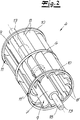
Die Querstromturbine
Die aus der Tragscheibe
Aus der Darstellung in
Aus einer vergleichenden Betrachtung der
Aus den
ZITATE ENTHALTEN IN DER BESCHREIBUNG QUOTES INCLUDE IN THE DESCRIPTION
Diese Liste der vom Anmelder aufgeführten Dokumente wurde automatisiert erzeugt und ist ausschließlich zur besseren Information des Lesers aufgenommen. Die Liste ist nicht Bestandteil der deutschen Patent- bzw. Gebrauchsmusteranmeldung. Das DPMA übernimmt keinerlei Haftung für etwaige Fehler oder Auslassungen.This list of the documents listed by the applicant has been generated automatically and is included solely for the better information of the reader. The list is not part of the German patent or utility model application. The DPMA assumes no liability for any errors or omissions.
Zitierte PatentliteraturCited patent literature
- DE 4105336 A1 [0002] DE 4105336 A1 [0002]
- DE 10110770 A1 [0003, 0004] DE 10110770 A1 [0003, 0004]
Claims (13)
Priority Applications (1)
| Application Number | Priority Date | Filing Date | Title |
|---|---|---|---|
| DE102015114237.6A DE102015114237B4 (en) | 2015-08-27 | 2015-08-27 | Cleaning device |
Applications Claiming Priority (1)
| Application Number | Priority Date | Filing Date | Title |
|---|---|---|---|
| DE102015114237.6A DE102015114237B4 (en) | 2015-08-27 | 2015-08-27 | Cleaning device |
Publications (2)
| Publication Number | Publication Date |
|---|---|
| DE102015114237A1 true DE102015114237A1 (en) | 2017-03-02 |
| DE102015114237B4 DE102015114237B4 (en) | 2021-05-20 |
Family
ID=58011360
Family Applications (1)
| Application Number | Title | Priority Date | Filing Date |
|---|---|---|---|
| DE102015114237.6A Active DE102015114237B4 (en) | 2015-08-27 | 2015-08-27 | Cleaning device |
Country Status (1)
| Country | Link |
|---|---|
| DE (1) | DE102015114237B4 (en) |
Cited By (1)
| Publication number | Priority date | Publication date | Assignee | Title |
|---|---|---|---|---|
| CN111715576A (en) * | 2020-05-13 | 2020-09-29 | 东风博泽汽车系统有限公司 | Dust removal device for motor rotor |
Citations (5)
| Publication number | Priority date | Publication date | Assignee | Title |
|---|---|---|---|---|
| DE4105336A1 (en) | 1991-02-21 | 1992-10-22 | Fedag Romanshorn Fa | SUCTION CLEANING TOOL |
| DE3879867T2 (en) * | 1987-10-23 | 1993-10-14 | Matsushita Electric Ind Co Ltd | Vacuum cleaner mouthpiece. |
| DE10051177A1 (en) * | 2000-04-21 | 2001-10-25 | Hoover Co | Suction cleaning nozzle for use in vacuum cleaner has nozzle body with elongated roller chamber which has suction inlet opening and roller in chamber extending partially through suction opening |
| DE10110770A1 (en) | 2000-08-31 | 2002-03-14 | Duepro Ag Romanshorn | Vacuum cleaning tool has self-adjusting air turbine with each deformable, adjustable turbine blade fixed to bearer disc at only one end, ending close to turbine chamber wall at other end |
| DE102013002841A1 (en) * | 2013-02-20 | 2014-08-21 | Düpro AG | Floor nozzle for use with suction port for connection to suction pipe of suction device, particularly vacuum cleaner, has suction slot that extends in axial direction of brush roller and has greater length than axial length of brush roller |
-
2015
- 2015-08-27 DE DE102015114237.6A patent/DE102015114237B4/en active Active
Patent Citations (6)
| Publication number | Priority date | Publication date | Assignee | Title |
|---|---|---|---|---|
| DE3879867T2 (en) * | 1987-10-23 | 1993-10-14 | Matsushita Electric Ind Co Ltd | Vacuum cleaner mouthpiece. |
| DE4105336A1 (en) | 1991-02-21 | 1992-10-22 | Fedag Romanshorn Fa | SUCTION CLEANING TOOL |
| DE10051177A1 (en) * | 2000-04-21 | 2001-10-25 | Hoover Co | Suction cleaning nozzle for use in vacuum cleaner has nozzle body with elongated roller chamber which has suction inlet opening and roller in chamber extending partially through suction opening |
| DE10110770A1 (en) | 2000-08-31 | 2002-03-14 | Duepro Ag Romanshorn | Vacuum cleaning tool has self-adjusting air turbine with each deformable, adjustable turbine blade fixed to bearer disc at only one end, ending close to turbine chamber wall at other end |
| DE10110768A1 (en) * | 2000-08-31 | 2002-03-14 | Duepro Ag Romanshorn | Vacuum cleaning tool has optimized air turbine with total volume between axial ends of turbine, turbine casing of 40,000 to 170,000 mm3; center volume of about 30-45 per cent of total |
| DE102013002841A1 (en) * | 2013-02-20 | 2014-08-21 | Düpro AG | Floor nozzle for use with suction port for connection to suction pipe of suction device, particularly vacuum cleaner, has suction slot that extends in axial direction of brush roller and has greater length than axial length of brush roller |
Cited By (2)
| Publication number | Priority date | Publication date | Assignee | Title |
|---|---|---|---|---|
| CN111715576A (en) * | 2020-05-13 | 2020-09-29 | 东风博泽汽车系统有限公司 | Dust removal device for motor rotor |
| CN111715576B (en) * | 2020-05-13 | 2021-10-01 | 东风博泽汽车系统有限公司 | Dust removal device for motor rotor |
Also Published As
| Publication number | Publication date |
|---|---|
| DE102015114237B4 (en) | 2021-05-20 |
Similar Documents
| Publication | Publication Date | Title |
|---|---|---|
| DE602005003797T2 (en) | axial fan | |
| DE10327574B4 (en) | Impeller for a fuel pump | |
| DE102005017575A1 (en) | Rotary pump with a pump housing and two double-winged rotary pistons | |
| DE2225010A1 (en) | Rotary air filter | |
| EP2643595B1 (en) | Self cleaning radial flow pump with recirculation behind the impeller | |
| EP3478389B1 (en) | Backwash filter | |
| DE1453730C3 (en) | Radial centrifugal pump impeller | |
| DE102011078017B3 (en) | pump | |
| DE102015114237B4 (en) | Cleaning device | |
| DE102005042228B4 (en) | suction machine | |
| DE1653921C3 (en) | Rotary piston pump | |
| EP2766608B1 (en) | Centrifugal pump for fluid containing solid particles with sealing of a gap | |
| DE3717229A1 (en) | SHEET WHEEL SMALL DELIVERY PERFORMANCE, IN PARTICULAR FOR COOLANT PUMPS | |
| DE3117557C2 (en) | ||
| EP2275017B1 (en) | Dishwasher with a circulating pump | |
| DE102007025402B4 (en) | Pump for a household appliance | |
| DE102005040305B4 (en) | Side channel machine | |
| EP1053402B1 (en) | Centrifugal pump impeller having a radial structure | |
| DE102009056432A1 (en) | Air cleaner for self-propelled harvesting machine, has rotary supported filter screen and cleaning unit that is arranged on air inlet side of filter screen | |
| DE102016110224B4 (en) | Centrifugal pump and impeller for a centrifugal pump | |
| DE102014004420A1 (en) | Centrifugal pump with cutting device | |
| WO2018158260A1 (en) | Fan wheel | |
| EP0995906A1 (en) | Motor-driven double pump of the centrifugal type | |
| DE2724829C2 (en) | Cross-flow radial fan unit | |
| DE102011117826A1 (en) | Cooking vapor fume hood, has vanes arranged concentric at axis, and motor-side covering plate comprising countersink unit protruded in axial direction in middle area of covering plates, and motor arranged partially in countersink unit |
Legal Events
| Date | Code | Title | Description |
|---|---|---|---|
| R012 | Request for examination validly filed | ||
| R016 | Response to examination communication | ||
| R018 | Grant decision by examination section/examining division | ||
| R020 | Patent grant now final |