DE102015106929B3 - vehicle lamp - Google Patents
vehicle lamp Download PDFInfo
- Publication number
- DE102015106929B3 DE102015106929B3 DE102015106929.6A DE102015106929A DE102015106929B3 DE 102015106929 B3 DE102015106929 B3 DE 102015106929B3 DE 102015106929 A DE102015106929 A DE 102015106929A DE 102015106929 B3 DE102015106929 B3 DE 102015106929B3
- Authority
- DE
- Germany
- Prior art keywords
- circuit board
- carrier
- vehicle lamp
- carriers
- lamp according
- Prior art date
- Legal status (The legal status is an assumption and is not a legal conclusion. Google has not performed a legal analysis and makes no representation as to the accuracy of the status listed.)
- Expired - Fee Related
Links
Images


Classifications
-
- F—MECHANICAL ENGINEERING; LIGHTING; HEATING; WEAPONS; BLASTING
- F21—LIGHTING
- F21S—NON-PORTABLE LIGHTING DEVICES; SYSTEMS THEREOF; VEHICLE LIGHTING DEVICES SPECIALLY ADAPTED FOR VEHICLE EXTERIORS
- F21S41/00—Illuminating devices specially adapted for vehicle exteriors, e.g. headlamps
- F21S41/10—Illuminating devices specially adapted for vehicle exteriors, e.g. headlamps characterised by the light source
- F21S41/14—Illuminating devices specially adapted for vehicle exteriors, e.g. headlamps characterised by the light source characterised by the type of light source
- F21S41/141—Light emitting diodes [LED]
- F21S41/147—Light emitting diodes [LED] the main emission direction of the LED being angled to the optical axis of the illuminating device
-
- F—MECHANICAL ENGINEERING; LIGHTING; HEATING; WEAPONS; BLASTING
- F21—LIGHTING
- F21S—NON-PORTABLE LIGHTING DEVICES; SYSTEMS THEREOF; VEHICLE LIGHTING DEVICES SPECIALLY ADAPTED FOR VEHICLE EXTERIORS
- F21S41/00—Illuminating devices specially adapted for vehicle exteriors, e.g. headlamps
- F21S41/10—Illuminating devices specially adapted for vehicle exteriors, e.g. headlamps characterised by the light source
- F21S41/19—Attachment of light sources or lamp holders
- F21S41/192—Details of lamp holders, terminals or connectors
-
- F—MECHANICAL ENGINEERING; LIGHTING; HEATING; WEAPONS; BLASTING
- F21—LIGHTING
- F21S—NON-PORTABLE LIGHTING DEVICES; SYSTEMS THEREOF; VEHICLE LIGHTING DEVICES SPECIALLY ADAPTED FOR VEHICLE EXTERIORS
- F21S41/00—Illuminating devices specially adapted for vehicle exteriors, e.g. headlamps
- F21S41/30—Illuminating devices specially adapted for vehicle exteriors, e.g. headlamps characterised by reflectors
- F21S41/32—Optical layout thereof
- F21S41/321—Optical layout thereof the reflector being a surface of revolution or a planar surface, e.g. truncated
-
- F—MECHANICAL ENGINEERING; LIGHTING; HEATING; WEAPONS; BLASTING
- F21—LIGHTING
- F21S—NON-PORTABLE LIGHTING DEVICES; SYSTEMS THEREOF; VEHICLE LIGHTING DEVICES SPECIALLY ADAPTED FOR VEHICLE EXTERIORS
- F21S43/00—Signalling devices specially adapted for vehicle exteriors, e.g. brake lamps, direction indicator lights or reversing lights
- F21S43/10—Signalling devices specially adapted for vehicle exteriors, e.g. brake lamps, direction indicator lights or reversing lights characterised by the light source
- F21S43/13—Signalling devices specially adapted for vehicle exteriors, e.g. brake lamps, direction indicator lights or reversing lights characterised by the light source characterised by the type of light source
- F21S43/14—Light emitting diodes [LED]
-
- F—MECHANICAL ENGINEERING; LIGHTING; HEATING; WEAPONS; BLASTING
- F21—LIGHTING
- F21S—NON-PORTABLE LIGHTING DEVICES; SYSTEMS THEREOF; VEHICLE LIGHTING DEVICES SPECIALLY ADAPTED FOR VEHICLE EXTERIORS
- F21S43/00—Signalling devices specially adapted for vehicle exteriors, e.g. brake lamps, direction indicator lights or reversing lights
- F21S43/10—Signalling devices specially adapted for vehicle exteriors, e.g. brake lamps, direction indicator lights or reversing lights characterised by the light source
- F21S43/19—Attachment of light sources or lamp holders
- F21S43/195—Details of lamp holders, terminals or connectors
-
- F—MECHANICAL ENGINEERING; LIGHTING; HEATING; WEAPONS; BLASTING
- F21—LIGHTING
- F21S—NON-PORTABLE LIGHTING DEVICES; SYSTEMS THEREOF; VEHICLE LIGHTING DEVICES SPECIALLY ADAPTED FOR VEHICLE EXTERIORS
- F21S45/00—Arrangements within vehicle lighting devices specially adapted for vehicle exteriors, for purposes other than emission or distribution of light
- F21S45/40—Cooling of lighting devices
- F21S45/47—Passive cooling, e.g. using fins, thermal conductive elements or openings
-
- F—MECHANICAL ENGINEERING; LIGHTING; HEATING; WEAPONS; BLASTING
- F21—LIGHTING
- F21S—NON-PORTABLE LIGHTING DEVICES; SYSTEMS THEREOF; VEHICLE LIGHTING DEVICES SPECIALLY ADAPTED FOR VEHICLE EXTERIORS
- F21S45/00—Arrangements within vehicle lighting devices specially adapted for vehicle exteriors, for purposes other than emission or distribution of light
- F21S45/40—Cooling of lighting devices
- F21S45/49—Attachment of the cooling means
Abstract
Die Erfindung betrifft eine Fahrzeuglampe, die eine Schaltungsplatte (10), mindestens einen Träger (20), der schräg mit der Schaltungsplatte (10) verbunden ist, und mindestens ein Leuchtelement (40) umfasst, wobei jeder Träger (20) mindestens ein Leuchtelement (40) trägt, das mit der Schaltungsplatte (10) elektrisch verbunden ist.The invention relates to a vehicle lamp comprising a circuit board (10), at least one support (20) connected obliquely to the circuit board (10) and at least one luminous element (40), each support (20) comprising at least one luminous element (10). 40) which is electrically connected to the circuit board (10).
Description
[Technisches Gebiet][Technical area]
Die Erfindung betrifft eine Fahrzeuglampe.The invention relates to a vehicle lamp.
[Stand der Technik][State of the art]
Eine herkömmliche Fahrzeuglampe weist einen Kühlkörper auf, in dem ein Leuchtelement angeordnet ist, das Licht in einem bestimmten Winkel abstrahlt. Das Licht wird von einer Reflexionsfläche an der Innenseite des Lampengehäuses reflektiert.A conventional vehicle lamp has a heat sink in which a luminous element is arranged, which emits light at a certain angle. The light is reflected by a reflection surface on the inside of the lamp housing.
Bei einer solchen Fahrzeuglampe wird das Leuchtelement durch eine Plusleitung und eine Minusleitung mit einer Schaltungsplatte verbunden. Dadurch wird der Raumbedarf vergrößert. Der Kühlkörper und das Lampengehäuse benötigen Durchführungslöcher für die elektrischen Leitungen. Die elektrischen Leitungen sind freiliegend.In such a vehicle lamp, the light emitting element is connected to a circuit board through a plus line and a minus line. This increases the space requirement. The heat sink and the lamp housing require feedthrough holes for the electrical wiring. The electrical cables are exposed.
Aus den Dokumenten
Aus dem Dokument
Aus dem Dokument
Aus dem Dokument
Daher zielt der Erfinder darauf ab, eine Fahrzeuglampe bereitzustellen, die die oben genannten Nachteile der herkömmlichen Lösung beseitigen kann.Therefore, the inventor aims to provide a vehicle lamp which can eliminate the above-mentioned disadvantages of the conventional solution.
[Aufgabe der Erfindung]OBJECT OF THE INVENTION
Der Erfindung liegt die Aufgabe zugrunde, eine platzsparende Fahrzeuglampe zu schaffen, wobei die Träger der Leuchtelemente schräg an der Schaltungsplatte befestigt sind und jeweils eine Schaltung besitzen, wodurch die Schaltungsplatte direkt mit den Leuchtelementen verbunden werden kann, sodass keine elektrischen Leitungen und keine Durchführungslöcher erforderlich sind.The invention has for its object to provide a space-saving vehicle lamp, wherein the carrier of the lighting elements are mounted obliquely on the circuit board and each having a circuit, whereby the circuit board can be connected directly to the lighting elements, so that no electrical lines and no feedthrough holes are required ,
Diese Aufgabe wird durch die erfindungsgemäße Fahrzeuglampe gelöst, die eine Schaltungplatte, mindestens einen Träger, der schräg mit der Schaltungsplatte verbunden ist, und mindestens ein Leuchtelement umfasst, wobei jeder Träger mindestens ein Leuchtelement trägt, das mit der Schaltungsplatte elektrisch verbunden ist.This object is achieved by the vehicle lamp according to the invention, which comprises a circuit board, at least one carrier which is obliquely connected to the circuit board, and at least one luminous element, wherein each carrier carries at least one luminous element which is electrically connected to the circuit board.
[Kurze Beschreibung der Zeichnungen][Brief Description of the Drawings]
[Wege zur Ausführung der Erfindung][Means for Carrying out the Invention]
Weitere Einzelheiten, Merkmale und Vorteile der Erfindung ergeben sich aus der nachfolgenden detaillierten Beschreibung in Verbindung mit den beigefügten Zeichnungen.Further details, features and advantages of the invention will become apparent from the following detailed description taken in conjunction with the accompanying drawings.
Die
Der Träger
Das Leuchtelement
Im vorliegenden Ausführungsbeispiel umfasst die Fahrzeuglampe
Die Fahrzeuglampe
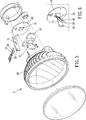
Die
In allen Ausführungsbeispielen in den
Im Vergleich mit der herkömmlichen Lösung kann die Erfindung einen großen Teil des Lichtes auf das Lampengehäuse strahlen, wodurch das Licht gesammelt und in einer Richtung abgestrahlt wird.In comparison with the conventional solution, the invention can radiate a large part of the light on the lamp housing, whereby the light is collected and emitted in one direction.
Der Träger besitzt eine Schaltung und wird mit einem Ende in die Schaltungsplatte gesteckt, wodurch die elektrischen Leitungen verdeckt bleiben und der Raumbedarf verkleinert wird.The carrier has a circuit and is inserted with one end in the circuit board, whereby the electrical cables remain hidden and the space required is reduced.
Zusammenfassend ist festzustellen, dass die Träger durch die seitliche Ausnehmungen (oder Durchgangslöcher) miteinander verbunden sind, wodurch eine Beschränkung (Lichtabschattung) für die Beleuchtung erheblich reduziert wird. Zwei Träger werden gekreuzt miteinander verbunden und bilden eine X-Form, wodurch eine gegenseitige Abstützung erreicht wird. Zudem kann die Wärme schnell an den Kühlkörper abgeleitet werden. Die Leuchtelemente können an den Oberseiten der Träger, die gekreuzt miteinander verbunden sind und eine X-Form bilden, angeordnet sein, wodurch das Licht der Fahrzeuglampe gleichmäßiger ist.In summary, it can be stated that the carriers are connected to one another by the lateral recesses (or through-holes), whereby a limitation (light shading) for the illumination is considerably reduced. Two carriers are crossed with each other and form an X-shape, whereby a mutual support is achieved. In addition, the heat can be quickly dissipated to the heat sink. The lighting elements may be arranged on the upper sides of the carriers, which are crossed with each other and form an X-shape, whereby the light of the vehicle lamp is more uniform.
BezugszeichenlisteLIST OF REFERENCE NUMBERS
- 11
- Fahrzeuglampevehicle lamp
- 22
- Fahrzeuglampevehicle lamp
- 1010
- Schaltungsplattecircuit board
- 1111
- Lochhole
- 2020
- Trägercarrier
- 2121
- Ausnehmungrecess
- 2222
- SteckfußSteckfuß
- 2323
- Schaltungcircuit
- 3030
- Trägercarrier
- 3131
- DurchgangslochThrough Hole
- 3232
- Trägercarrier
- 3333
- Trägercarrier
- 3434
- Trägercarrier
- 3535
- Trägercarrier
- 3636
- Trägercarrier
- 4040
- Leuchtelementlight element
- 5050
- Kühlkörperheatsink
- 5151
- Steckschlitzinsertion slot
- 6060
- Lampengehäuselamp housing
Claims (9)
Priority Applications (1)
| Application Number | Priority Date | Filing Date | Title |
|---|---|---|---|
| DE102015106929.6A DE102015106929B3 (en) | 2015-05-04 | 2015-05-04 | vehicle lamp |
Applications Claiming Priority (1)
| Application Number | Priority Date | Filing Date | Title |
|---|---|---|---|
| DE102015106929.6A DE102015106929B3 (en) | 2015-05-04 | 2015-05-04 | vehicle lamp |
Publications (1)
| Publication Number | Publication Date |
|---|---|
| DE102015106929B3 true DE102015106929B3 (en) | 2016-09-01 |
Family
ID=56682799
Family Applications (1)
| Application Number | Title | Priority Date | Filing Date |
|---|---|---|---|
| DE102015106929.6A Expired - Fee Related DE102015106929B3 (en) | 2015-05-04 | 2015-05-04 | vehicle lamp |
Country Status (1)
| Country | Link |
|---|---|
| DE (1) | DE102015106929B3 (en) |
Citations (5)
| Publication number | Priority date | Publication date | Assignee | Title |
|---|---|---|---|---|
| JP2004127782A (en) * | 2002-10-04 | 2004-04-22 | Ichikoh Ind Ltd | Vehicle lamp and lighting device |
| WO2007057818A2 (en) * | 2005-11-17 | 2007-05-24 | Philips Intellectual Property & Standards Gmbh | Lighting device and method for directing light |
| DE10341884B4 (en) * | 2003-09-09 | 2007-10-18 | Intedis Gmbh & Co. Kg | Flexible circuit carrier arrangement |
| EP1632711B1 (en) * | 2004-09-01 | 2009-11-18 | Pollmann Austria OHG | Supporting assembly for light sources |
| DE102008039071A1 (en) * | 2008-08-21 | 2010-02-25 | Hella Kgaa Hueck & Co. | Lighting device for use as e.g. headlight, in corner area of body opening of vehicle, has LED-element and/or LED-carrier that are arranged in region of recess, where LED-element is connected to electrical connection of conductor plate |
-
2015
- 2015-05-04 DE DE102015106929.6A patent/DE102015106929B3/en not_active Expired - Fee Related
Patent Citations (5)
| Publication number | Priority date | Publication date | Assignee | Title |
|---|---|---|---|---|
| JP2004127782A (en) * | 2002-10-04 | 2004-04-22 | Ichikoh Ind Ltd | Vehicle lamp and lighting device |
| DE10341884B4 (en) * | 2003-09-09 | 2007-10-18 | Intedis Gmbh & Co. Kg | Flexible circuit carrier arrangement |
| EP1632711B1 (en) * | 2004-09-01 | 2009-11-18 | Pollmann Austria OHG | Supporting assembly for light sources |
| WO2007057818A2 (en) * | 2005-11-17 | 2007-05-24 | Philips Intellectual Property & Standards Gmbh | Lighting device and method for directing light |
| DE102008039071A1 (en) * | 2008-08-21 | 2010-02-25 | Hella Kgaa Hueck & Co. | Lighting device for use as e.g. headlight, in corner area of body opening of vehicle, has LED-element and/or LED-carrier that are arranged in region of recess, where LED-element is connected to electrical connection of conductor plate |
Similar Documents
| Publication | Publication Date | Title |
|---|---|---|
| EP2147245B1 (en) | Lighting device, backlighting device, and display device | |
| DE112006000920B4 (en) | LED unit and LED lighting lamp using the LED unit | |
| DE10303969B4 (en) | Light-emitting diode arrangement with a light-emitting diode and a plurality of light-emitting diodes | |
| EP3167224B1 (en) | Semiconductor lamp | |
| DE102014000188A1 (en) | Motor drive unit with heat radiator | |
| DE202008006325U1 (en) | Heat dissipation arrangement and lamp with this | |
| DE102013103936A1 (en) | Light emitting device | |
| DE102010052020B4 (en) | Lighting and / or display device | |
| DE202005021754U1 (en) | Light-emitting panel | |
| DE102007043903A1 (en) | Luminous device | |
| WO2009033641A1 (en) | Lamp | |
| DE112011101327T5 (en) | Light emitting device | |
| DE102019104792A1 (en) | LIGHT-EMITTING MODULE | |
| DE202010004870U1 (en) | LED matrix | |
| DE102015106929B3 (en) | vehicle lamp | |
| DE102014215063B4 (en) | Vehicle lamp with a light-emitting element with two printed circuit boards and a reflector on a circuit structure | |
| DE102011117483A1 (en) | LED bulb, has ribs provided between LED module and base, and piston covering module, partially or completely including semi reflection layer at inner wall, and supplying current to module so that light of module is reflected by layer | |
| WO2015040240A1 (en) | Lamp | |
| DE102008026627B3 (en) | Cooling system for LED chip arrangement | |
| EP2938170A1 (en) | Holder for SMD light emitting diode | |
| DE10162404A1 (en) | Circuit arrangement for driving LEDs especially in motor vehicle, has power component and LED arranged on common circuit board or common conducting film | |
| DE60303655T2 (en) | Positioning and supply module for light emitting diode | |
| DE102016101757A1 (en) | CIRCUIT MODULE WITH SURFACE MOUNTABLE SURFACE BLOCKS FOR CONNECTING A PCB | |
| DE202010008806U1 (en) | Flexible LED packaging arrangement | |
| DE202011104204U1 (en) | Cooling device for light-emitting diode lamp |
Legal Events
| Date | Code | Title | Description |
|---|---|---|---|
| R012 | Request for examination validly filed | ||
| R082 | Change of representative |
Representative=s name: LANGPATENT ANWALTSKANZLEI IP LAW FIRM, DE |
|
| R016 | Response to examination communication | ||
| R016 | Response to examination communication | ||
| R018 | Grant decision by examination section/examining division | ||
| R020 | Patent grant now final | ||
| R119 | Application deemed withdrawn, or ip right lapsed, due to non-payment of renewal fee | ||
| R079 | Amendment of ipc main class |
Free format text: PREVIOUS MAIN CLASS: B60Q0001000000 Ipc: B60Q0001040000 |