DE102014215552B4 - Exhibition system for doors and / or door frames - Google Patents
Exhibition system for doors and / or door frames Download PDFInfo
- Publication number
- DE102014215552B4 DE102014215552B4 DE102014215552.5A DE102014215552A DE102014215552B4 DE 102014215552 B4 DE102014215552 B4 DE 102014215552B4 DE 102014215552 A DE102014215552 A DE 102014215552A DE 102014215552 B4 DE102014215552 B4 DE 102014215552B4
- Authority
- DE
- Germany
- Prior art keywords
- exhibition
- frame
- doors
- wall
- door
- Prior art date
- Legal status (The legal status is an assumption and is not a legal conclusion. Google has not performed a legal analysis and makes no representation as to the accuracy of the status listed.)
- Expired - Fee Related
Links
- 230000000295 complement effect Effects 0.000 claims abstract description 43
- 238000006073 displacement reaction Methods 0.000 claims description 4
- 239000000463 material Substances 0.000 claims description 3
- 238000010276 construction Methods 0.000 description 2
- 238000005034 decoration Methods 0.000 description 2
- 229910000831 Steel Inorganic materials 0.000 description 1
- 239000011521 glass Substances 0.000 description 1
- 230000005484 gravity Effects 0.000 description 1
- 238000009434 installation Methods 0.000 description 1
- 238000012797 qualification Methods 0.000 description 1
- 238000007634 remodeling Methods 0.000 description 1
- 239000010959 steel Substances 0.000 description 1
- 239000002023 wood Substances 0.000 description 1
Images


Classifications
-
- A—HUMAN NECESSITIES
- A47—FURNITURE; DOMESTIC ARTICLES OR APPLIANCES; COFFEE MILLS; SPICE MILLS; SUCTION CLEANERS IN GENERAL
- A47F—SPECIAL FURNITURE, FITTINGS, OR ACCESSORIES FOR SHOPS, STOREHOUSES, BARS, RESTAURANTS OR THE LIKE; PAYING COUNTERS
- A47F7/00—Show stands, hangers, or shelves, adapted for particular articles or materials
-
- E—FIXED CONSTRUCTIONS
- E04—BUILDING
- E04H—BUILDINGS OR LIKE STRUCTURES FOR PARTICULAR PURPOSES; SWIMMING OR SPLASH BATHS OR POOLS; MASTS; FENCING; TENTS OR CANOPIES, IN GENERAL
- E04H1/00—Buildings or groups of buildings for dwelling or office purposes; General layout, e.g. modular co-ordination or staggered storeys
- E04H1/12—Small buildings or other erections for limited occupation, erected in the open air or arranged in buildings, e.g. kiosks, waiting shelters for bus stops or for filling stations, roofs for railway platforms, watchmen's huts or dressing cubicles
- E04H1/1272—Exhibition stands
Landscapes
- Engineering & Computer Science (AREA)
- Architecture (AREA)
- Civil Engineering (AREA)
- Structural Engineering (AREA)
- Freezers Or Refrigerated Showcases (AREA)
- Wing Frames And Configurations (AREA)
Abstract
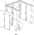
Ausstellungssystem (1) für Türen (21) und/oder Türzargen (22), umfassend zumindest einen Ausstellungsrahmen (10), wobei der Ausstellungsrahmen (10) zumindest einen vertikalen Ständer (11) und zumindest einen horizontalen Querbalken (12) umfasst, dadurch gekennzeichnet, dass der Ausstellungsrahmen (10) zumindest bereichsweise erste Rastmittel (17) für ein erstes komplementäres Rastelement (27) aufweist; weiter umfassend zumindest eine Wandscheibe (20), wobei die Wandscheibe (20) einen Montagerahmen (26) und zumindest eine Tür (21) und/oder eine Türzarge (22) umfasst, wobei der Montagerahmen (26) zumindest ein erstes komplementäres Rastelement (27) aufweist, und das erste komplementäre Rastelement (27) derart ausgebildet ist, dass es mit den ersten Rastmitteln (17) des Ausstellungsrahmens (10) in Eingriff gebracht werden kann, um Wandscheiben (26) am Ausstellungsrahmen (10) derart anzubringen, dass die Hauptebene (120) der Wandscheibe(n) (20) im Wesentlichen vertikal ausgerichtet ist, und dass zumindest das erste komplementäre Rastelement (27) und/oder das erste Rastmittel (17) des Ausstellungsrahmens (10) zumindest eine Anlagefläche (117, 127) aufweist, welche abweichend von der Vertikalen (100) und Horizontalen (101) orientiert ist, und zumindest bereichsweise mit zumindest einem Teil des ersten Rastmittels (17) oder des ersten komplementären Rastelements (27) in direktem Kontakt steht und so während des Anbringens eine translatorische Bewegung parallel zu dieser Anlagefläche (117, 127) ermöglicht, wodurch die Wandscheibe(n) (20) in ihrer endgültigen Ausrichtung gesichert wird (werden).Exhibition system (1) for doors (21) and / or door frames (22), comprising at least one exhibition frame (10), wherein the exhibition frame (10) comprises at least one vertical stand (11) and at least one horizontal crossbar (12), characterized in that the display frame (10) has at least partially first latching means (17) for a first complementary latching element (27); further comprising at least one wall plate (20), wherein the wall plate (20) comprises a mounting frame (26) and at least one door (21) and / or a door frame (22), wherein the mounting frame (26) at least a first complementary locking element (27 ), and the first complementary latching element (27) is designed such that it can be brought into engagement with the first latching means (17) of the display frame (10) to mount wall plates (26) on the display frame (10) such that the Main plane (120) of the wall disc (s) (20) is oriented substantially vertically, and that at least the first complementary latching element (27) and / or the first latching means (17) of the exhibition frame (10) at least one contact surface (117, 127) which is oriented differently from the vertical (100) and horizontal (101), and at least partially with at least a portion of the first locking means (17) or the first complementary locking element (27) in direct Kont akt and thus during the mounting allows a translational movement parallel to this bearing surface (117, 127), whereby the wall plate (s) (20) is secured in its final orientation (are).
Description
I. Gebiet der ErfindungI. Field of the Invention
Die Erfindung betrifft ein Ausstellungssystem für Türen und/oder Türzargen umfassend zumindest einen Ausstellungsrahmen und zumindest eine Wandscheibe.The invention relates to an exhibition system for doors and / or door frames comprising at least one exhibition frame and at least one wall plate.
II. Stand der TechnikII. State of the art
Aus dem Stand der Technik und insbesondere aus dem Messebau sind Ausstellungssysteme bekannt, die zu Dekorationszwecken oder Informationszwecken in einem Ausstellungs- oder Verkaufsraum oder auf einem Messestand positioniert werden können. Solche Ausstellungssysteme unterstützen die Aufstellung von Türen, Fenstern oder ähnlichen flächigen Ausstellungsstücken dadurch, dass an den vertikalen Flächen dieser Ausstellungssysteme Türen, Fenster und/oder flächige Ausstellungsstücke angebracht werden können.Exhibition systems are known from the state of the art and in particular from trade fair construction, which can be positioned for decoration purposes or information purposes in an exhibition or sales room or on a trade fair stand. Such exhibition systems support the erection of doors, windows or similar flat exhibits by the fact that on the vertical surfaces of these exhibition systems doors, windows and / or flat exhibits can be mounted.
Typischerweise erfolgt die Montage der Ausstellungsstücke direkt am Ausstellungssystem, so dass umfangreiche Umbauarbeiten entstehen, wenn die Ausstellungsstücke ausgetauscht und/oder aktualisiert werden müssen. Die Ausstellungsstücke sind dabei regelmäßig durch herkömmliche lösbare Verbindungen, wie Schraub- oder Bolzenverbindungen direkt am Ausstellungssystem befestigt, was den Einsatz von Werkzeugen beim Austausch nötig macht.Typically, the exhibits are mounted directly on the exhibition system, so that extensive remodeling occurs when the exhibits have to be replaced and / or updated. The exhibits are regularly attached by conventional detachable connections, such as screw or bolt connections directly to the exhibition system, which makes the use of tools when replacing necessary.
Darüber hinaus müssen Ausstellungsstücke, welche aus mehreren Komponenten bestehen, wie beispielsweise die Kombination von Tür und entsprechender Türzarge, am Ort der Ausstellung direkt am Ausstellungssystem montiert werden, was den Einsatz von fachlich qualifiziertem Personal vor Ort erforderlich macht und einen zeitlichen Montageaufwand von ca. 1–2 Stunden je Türelement erfordert.In addition, exhibits that consist of several components, such as the combination of door and corresponding door frame, must be mounted directly on the exhibition system at the place of issue, which requires the use of technically qualified personnel on site and a time-consuming installation of about 1 -2 hours per door element required.
Ein solches System ist beispielsweise aus der
Aus der
Aus der
Aus der
Der Austausch von Ausstellungsstücken in bekannten Systemen ist zeitaufwendig, bedarf des Einsatzes von fachlich hierfür qualifiziertem Personal und von speziellen Werkzeugen und birgt die Gefahr der Beschädigung von Systemkomponenten sowie der Beschädigung von Ausstellungsstücken.The replacement of exhibits in known systems is time consuming, requires the use of professionally qualified personnel and special tools and involves the risk of damage to system components and damage to exhibits.
III. Zusammenfassung der ErfindungIII. Summary of the invention
Die Aufgabe der vorliegenden Erfindung ist, ein Ausstellungssystem für Türen und/oder Türzargen, oder für Fenstern und/oder Fensterrahmen sowie für allgemein flächige Ausstellungsstücke zu schaffen, welches die oben genannten Nachteile ausräumt. Insbesondere ist ein fachgerechter Austausch jederzeit auch durch Personen ohne spezielle Qualifikation möglich. Die Aufgabe wird erfindungsgemäß durch das Ausstellungssystem gemäß Anspruch 1 gelöst.The object of the present invention is to provide an exhibition system for doors and / or door frames, or for windows and / or window frames as well as for general flat exhibits, which eliminates the disadvantages mentioned above. In particular, a professional exchange is possible at any time by persons without special qualifications. The object is achieved by the exhibition system according to
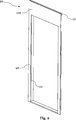
Ein besonderer Vorteil des erfindungsgemäßen Ausstellungssystems ist das Anbringen, das Ausstellen und der einfache Austausch kompletter Wandscheiben inkl. der darin vormontierten Ausstellungselemente, d. h. Innentürelement, Haustüre, Nebeneingangstüre oder Fenster. Eine Wandscheibe bezeichnet dabei eine Baugruppe, welche zumindest einen Montagerahmen und/oder ein Ausstellungselement (bspw. eine Tür und/oder eine Türzarge) umfasst. Weiterhin kann die Wandscheibe auch Haustüren, Nebeneingangstüren oder einen Fensterrahmen und/oder ein Fenster oder ein anderes flächiges Ausstellungsstück umfassen. Die Wandscheibe kann sowohl aus einzelnen Komponenten zusammengesetzt sein, als auch integral mit der Türzarge, dem Fensterrahmen, und/oder dem Montagerahmen ausgebildet. Eine integrale Ausbildung mit einem beliebigen flächigen Ausstellungsstück ist ebenfalls von der erfindungsgemäßen Wandscheibe umfasst, jedoch nicht bevorzugt.A particular advantage of the exhibition system according to the invention is the attachment, the exhibition and the simple replacement of complete wall panels including the pre-assembled exhibition elements, ie interior door element, front door, side door or window. A wall plate here refers to an assembly which comprises at least one mounting frame and / or an exhibition element (for example a door and / or a door frame). Furthermore, the wall panel may also include front doors, side entrance doors or a window frame and / or a window or other flat exhibit. The wall plate can be composed of individual components be formed as integral with the door frame, the window frame, and / or the mounting frame. An integral design with any flat display piece is also included in the wall plate according to the invention, but not preferred.
Flächige Ausstellungsstücke im Sinne der Erfindung sind flächige Gebilde, die ähnlich wie Türen im Wesentlichen vertikal angeordnet werden und beispielsweise Wohnungseingangstüren, Nebeneingangstüren, Innentüren oder Fensterrollläden, Jalousien und/oder Fensterläden, Wanddekore oder andere flächige Gebilde umfassen.Flat display items in the sense of the invention are flat structures which, like doors, are arranged substantially vertically and comprise, for example, entrance doors, side entrance doors, interior doors or window shutters, blinds and / or shutters, wall decorations or other flat structures.
Die Wandscheibe ist im montierten Zustand am Ausstellungsrahmen so anbringbar, dass die Hauptebene der Wandscheibe im Wesentlichen vertikal ausgerichtet ist. Die Hauptebene der Wandscheibe ist die Ebene, in welcher das Ausstellungsstück in der für den Gebrauch typischen Ausrichtung montiert wird. Beispielsweise ist es für die Tür und/oder Türzarge die Ebene, welche die Türöffnung und/oder das Türblatt beinhaltet. Für Fenster und/oder Fensterrahmen ist es sinngemäß die Ebene, welche die Fensteröffnung und/oder den Fensterflügel beinhaltet. Für flächige Ausstellungsstücke im Allgemeinen, ist es die Ebene, welche die größte geometrische Ausdehnung (Höhe × Breite) aufweist.When installed, the wall plate can be attached to the display frame in such a way that the main plane of the wall plate is oriented substantially vertically. The main plane of the wall plate is the plane in which the exhibit is mounted in the orientation typical for use. For example, it is for the door and / or door frame, the level which includes the door opening and / or the door leaf. For windows and / or window frames, it is analogous to the level that includes the window opening and / or the window sash. For flat exhibits in general, it is the plane that has the largest geometric extension (height × width).
Der Ausstellungsrahmen besteht aus zumindest einem vertikalen Ständer und zumindest einem horizontalen Querbalken. Vorzugsweise jedoch aus einem U-förmig angeordneten Ständerwerk. Vertikal bezeichnet dabei die Ausrichtung lotrecht zur Erdoberfläche, d. h. lotrecht auf den Boden, auf welchem das Ausstellungssystem aufgestellt ist. Horizontal bezeichnet die rechtwinklige Ausrichtung zur Vertikalen. Die Ausrichtung von Ständer und Querbalken bezieht sich jeweils auf deren Längsausrichtung, so dass die längste Seite des Ständers vertikal und die längste Seite des Querbalkens horizontal ausgerichtet ist.The exhibition frame consists of at least one vertical stand and at least one horizontal crossbar. Preferably, however, from a U-shaped stand system. Vertical refers to the orientation perpendicular to the earth's surface, d. H. perpendicular to the floor on which the exhibition system is set up. Horizontal refers to the right-angled orientation to the vertical. The orientation of the uprights and crossbeams always refers to their longitudinal orientation, so that the longest side of the uprights is vertical and the longest side of the crossbeam horizontally aligned.
Ständer und Querbalken bilden im montierten Zustand den Ausstellungsrahmen, welcher vorzugsweise am Ort der Ausstellung verbleibt, wohingegen die vormontierten Wandscheiben austauschbar sind. Durch den Austausch komplett montierter Wandscheiben kann so eine zeitlich veränderliche und kundenspezifische Ausstellung erfolgen, ohne das vollständige Ausstellungssystem um- oder abbauen zu müssen.Stand and crossbars in the assembled state form the exhibition frame, which preferably remains at the location of the exhibition, whereas the pre-assembled wall panels are interchangeable. By exchanging completely assembled wall panels, a time-varying and customer-specific exhibition can be carried out without having to rebuild or dismantle the entire exhibition system.
Der Ausstellungsrahmen ist vorzugsweise modular in U-Form aufgebaut, wobei ein Modul des Ausstellungsrahmens die Aufnahme von vorzugsweise vier, zumindest jedoch einer Wandscheibe ermöglicht. Ein Modul des Ausstellungsrahmens weist vorzugsweise eine Öffnung auf, welche seitlich von Ständern und/oder Querbalken begrenzt wird. Diese Öffnung des Moduls des Ausstellungsrahmens ermöglicht bei angebrachter Wandscheibe die Nutzung der ausgestellten Türe oder des ausgestellten Fensters in der Weise, dass die Funktion vollumfänglich gewährleistet und ein Öffnen und Schließen möglich ist.The display frame is preferably constructed in a modular U-shape, wherein a module of the exhibition frame allows the inclusion of preferably four, but at least one wall plate. A module of the exhibition frame preferably has an opening which is bounded laterally by uprights and / or crossbeams. This opening of the module of the exhibition frame allows with attached wall plate, the use of the issued door or the issued window in such a way that the function fully guaranteed and an opening and closing is possible.
Im Standard kann ein Modul des Ausstellungsrahmens vier Wandscheiben aufnehmen, in der Art, dass die Öffnungen des Moduls auf jeder Seite des Ausstellungsrahmens, also von beiden Seiten durch ein Türelement, eine Nebeneingangstüre, eine Haustüre oder einem Fenster, einen Fensterrahmen und/oder einem flächigem Ausstellungsstück verdeckt und/oder begrenzt ist.By default, a module of the exhibition frame can accommodate four wall panels, in such a way that the openings of the module on each side of the exhibition frame, ie from both sides by a door element, a side door, a front door or a window, a window frame and / or a flat Exhibit is obscured and / or limited.
Der Ausstellungsrahmen kann aus einer beliebigen Anzahl von Modulen bestehen, welche vorzugsweise in U-Form angeordnet werden können. Dadurch ist das System flexibel an die jeweiligen Ausstellungsräume anpassbar. Eine weitere mögliche Anordnung der Module ist eine Anordnung in Form einer Kette, wobei die Kette verzweigt sein kann. Weiterhin können die Module in Form eines Polygons, vorzugsweise in Form eines Rechtecks angeordnet werden, wobei die Polygone und/oder Rechtecke in Form von offenen Polygonen und/oder Rechtecken ausgebildet sein können.The display frame may consist of any number of modules, which may be preferably arranged in a U-shape. As a result, the system can be flexibly adapted to the respective exhibition spaces. Another possible arrangement of the modules is an arrangement in the form of a chain, wherein the chain can be branched. Furthermore, the modules may be arranged in the form of a polygon, preferably in the form of a rectangle, wherein the polygons and / or rectangles may be in the form of open polygons and / or rectangles.
Die einzelnen Module des Ausstellungsrahmens sind vorzugsweise ebenfalls modular aufgebaut, um den einfachen Austausch einzelner Modulkomponenten am Ort der Ausstellung sicher zu stellen. Vorzugsweise weisen Modulkomponenten, wie Ständer und/oder Querbalken die gleichen Dimensionen auf. Somit wird eine kleine Teilezahl erzielt. Der schnelle Austausch beschädigter und/oder verschlissener Komponenten der Module des Ausstellungsrahmens kann folglich mit der Bevorratung kleiner Mengen an Ersatzteilen am Ort der Ausstellung sichergestellt werden.The individual modules of the exhibition frame are also preferably of modular construction in order to ensure the simple replacement of individual module components at the location of the exhibition. Preferably, module components, such as uprights and / or crossbeams, have the same dimensions. Thus, a small number of parts is achieved. The rapid replacement of damaged and / or worn components of the modules of the exhibition frame can thus be ensured by stockpiling small quantities of spare parts at the point of issue.
Das Anbringen der Wandscheibe(n) am Ausstellungsrahmen erfolgt über das In-Eingriff-Bringen von einem ersten Rastmittel des Ausstellungsrahmens, das bevorzugt am horizontalen Querbalken angeordnet ist, und einem ersten komplementären Rastelement des Montagerahmens. Das erste Rastmittel kann integral z. B. mit dem Querbalken ausgebildet, oder an diesem als separates Teil montierbar sein. Ebenso kann das erste komplementäre Rastelement mit dem Montagerahmen integral ausgebildet oder am Montagerahmen als separates Teil montierbar sein.The attachment of the wall plate (s) on the exhibition frame via the engagement of a first locking means of the exhibition frame, which is preferably arranged on the horizontal crossbar, and a first complementary locking element of the mounting frame. The first locking means may be integrally z. B. formed with the crossbar, or be mounted on this as a separate part. Likewise, the first complementary locking element can be integrally formed with the mounting frame or mounted on the mounting frame as a separate part.
Durch das In-Eingriff-Bringen von ersten Rastmittel und ersten komplementären Rastelement, wird die Wandscheibe am Ausstellungsrahmen derart angebracht, dass die Hauptebene der Wandscheibe im Wesentlichen vertikal ausgerichtet ist.By engaging first latching means and first complementary latching element, the wall plate is attached to the display frame such that the main plane of the wall plate is substantially vertically aligned.
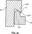
Das erste Rastmittel und/oder das erste komplementäre Rastelement weisen zumindest eine Anlagefläche auf, welche abweichend von der Horizontalen und der Vertikalen orientiert ist, d. h. die Anlagefläche ist geneigt. The first latching means and / or the first complementary latching element have at least one contact surface, which is oriented differently from the horizontal and the vertical, ie the contact surface is inclined.
Während des In-Eingriff-Bringens und in der sich anschließenden endgültigen Ausrichtung der Wandscheibe, steht die Anlagefläche des ersten Rastmittels und/oder des ersten komplementären Rastelements zumindest bereichsweise in direktem Kontakt mit dem komplementären Rastelement oder dem ersten Rastmittel.During the engagement and in the subsequent final alignment of the wall plate, the contact surface of the first locking means and / or the first complementary locking element is at least partially in direct contact with the complementary locking element or the first locking means.
Durch die Neigung der Anlagefläche bewegt sich die Wandscheibe, welche das komplementäre Rastelement umfasst, der Schwerkraft folgend translatorisch parallel zur Anlagefläche bis die endgültige Ausrichtung der Wandscheibe erreicht ist. In der endgültigen Ausrichtung ist die Wandscheibe durch das Eingreifen von erstem Rastmittel und ersten komplementären Rastelement gesichert.Due to the inclination of the contact surface, the wall plate, which comprises the complementary latching element, following gravity moves in translation parallel to the contact surface until the final alignment of the wall plate is reached. In the final orientation, the wall plate is secured by the engagement of the first locking means and the first complementary locking element.
Das Eigengewicht der Wandscheibe erzeugt aufgrund der vorteilhaften Neigung der Anlageflächen vorzugsweise eine Kraft und/oder ein Moment, welche die Wandscheibe gegen vertikales Verschieben und/oder ein Schwenken um eine horizontale und/oder vertikale Achse, in der Art sichert, dass die Ausstellungsstücke, insbesondere Türen und/oder Fenster ihrem bestimmungsgemäßen Gebrauch entsprechend bedient werden können. Im montierten Zustand bilden Ausstellungsrahmen und Wandscheibe vorzugsweise eine plane, flächenbündige Oberfläche, aus der ggf. nur das Ausstellungselement herausragt.Due to the advantageous inclination of the contact surfaces, the dead weight of the wall plate preferably generates a force and / or moment which secures the wall disk against vertical displacement and / or pivoting about a horizontal and / or vertical axis in such a way that the exhibits, in particular Doors and / or windows can be operated according to their intended use. In the mounted state, the exhibition frame and wall plate preferably form a flat, flush-mounted surface from which possibly only the exhibition element protrudes.
IV. Beschreibung der bevorzugten AusführungsformenIV. Description of the Preferred Embodiments
Im Folgenden wird nun eine detaillierte Beschreibung der Figuren gegeben.The following is a detailed description of the figures given.
In einer anderen bevorzugten Ausführungsform der Erfindung können am Ausstellungsrahmen
Wie in
In einer weiteren bevorzugten Ausführungsform der Erfindung können die äußerlich einheitlichen Wandscheiben
Des Weiteren können sich die ausgestellten und in einheitlichen Wandscheiben
In einer weiteren, nicht gezeigten Ausführungsform der Erfindung sind die Wandscheiben
Die zweiten komplementären Rastelemente
Die
BezugszeichenlisteLIST OF REFERENCE NUMBERS
- αα
- Winkelangle
- 11
- Ausstellungsystemexhibition system
- 1010
- Ausstellungsrahmenexhibition frame
- 1111
- Vertikaler StänderVertical stand
- 1212
- Horizontaler QuerbalkenHorizontal transom
- 1313
- Modulmodule
- 1717
- Erstes RastmittelFirst locking means
- 1818
- Zweites RastmittelSecond locking means
- 2020
- Wandscheibeshear wall
- 2121
- Türdoor
- 2222
- Türzargedoor frame
- 2323
- Fensterwindow
- 2424
- Fensterrahmenwindow frame
- 2525
- Flächiges AusstellungsstückFlat exhibit
- 2626
- Montagerahmenmounting frame
- 2727
- Erstes komplementäres RastelementFirst complementary locking element
- 2828
- Zweites komplementäres RastelementSecond complementary locking element
- 100100
- Vertikalevertical
- 101101
- Erste HorizontaleFirst horizontal
- 102102
- Zweite HorizontaleSecond horizontal
- 117117
- Anlagefläche des RastmittelsContact surface of the locking means
- 120120
- Hauptebene der WandscheibeMain plane of the wall plate
- 127127
- Anlagefläche des komplementären RastelementsContact surface of the complementary locking element
Claims (10)
Priority Applications (2)
| Application Number | Priority Date | Filing Date | Title |
|---|---|---|---|
| DE102014215552.5A DE102014215552B4 (en) | 2014-08-06 | 2014-08-06 | Exhibition system for doors and / or door frames |
| EP15176599.7A EP2982273A1 (en) | 2014-08-06 | 2015-07-14 | Display and exhibition system for doors and door frames |
Applications Claiming Priority (1)
| Application Number | Priority Date | Filing Date | Title |
|---|---|---|---|
| DE102014215552.5A DE102014215552B4 (en) | 2014-08-06 | 2014-08-06 | Exhibition system for doors and / or door frames |
Publications (2)
| Publication Number | Publication Date |
|---|---|
| DE102014215552A1 DE102014215552A1 (en) | 2016-02-11 |
| DE102014215552B4 true DE102014215552B4 (en) | 2017-07-06 |
Family
ID=53793986
Family Applications (1)
| Application Number | Title | Priority Date | Filing Date |
|---|---|---|---|
| DE102014215552.5A Expired - Fee Related DE102014215552B4 (en) | 2014-08-06 | 2014-08-06 | Exhibition system for doors and / or door frames |
Country Status (2)
| Country | Link |
|---|---|
| EP (1) | EP2982273A1 (en) |
| DE (1) | DE102014215552B4 (en) |
Families Citing this family (2)
| Publication number | Priority date | Publication date | Assignee | Title |
|---|---|---|---|---|
| US10070739B2 (en) | 2014-01-29 | 2018-09-11 | Liberty Hardware Mfg. Corp. | Shower door assembly display |
| CN115363382B (en) * | 2022-07-11 | 2024-03-29 | 上海合壹未来文化科技有限公司 | Space stereoscopic device for exhibition |
Citations (6)
| Publication number | Priority date | Publication date | Assignee | Title |
|---|---|---|---|---|
| US3650071A (en) * | 1970-09-08 | 1972-03-21 | Southeastern Aluminum Products | Panel frame assembly |
| DE29806435U1 (en) * | 1998-04-08 | 1998-06-10 | Friedrich Blanke GmbH, 49186 Bad Iburg | Presentation of doors or windows |
| DE20210901U1 (en) * | 2002-07-16 | 2002-10-10 | Obuk Haustürfüllungen GmbH, 59302 Oelde | Arrangement for the exhibition of doors, windows or similar flat structures |
| DE202007006424U1 (en) * | 2007-05-04 | 2007-07-05 | Umdasch Shop Concept Gmbh | Display stand comprises back panels with perforations which fit into horizontal profiled rails, vertical bars with slots for hanging articles to be displayed being hooked into perforations or into slots in horizontal rails |
| WO2007090301A1 (en) * | 2006-02-07 | 2007-08-16 | Visplay International Ag | Apparutus for displaying goods, having a horizontally arranged support beam |
| DE202007000038U1 (en) * | 2007-10-02 | 2007-12-27 | Hoen, Uwe | Device for the presentation of door, gate and / or window elements |
Family Cites Families (3)
| Publication number | Priority date | Publication date | Assignee | Title |
|---|---|---|---|---|
| FR2131891A1 (en) * | 1971-04-01 | 1972-11-17 | Gasc Fernand | |
| DE8801936U1 (en) * | 1988-02-15 | 1988-03-31 | MAHO AG, 8962 Pfronten | Trade fair and exhibition booth |
| CA2310869C (en) * | 1999-06-04 | 2003-08-26 | Teknion Furniture Systems Limited | Wall system |
-
2014
- 2014-08-06 DE DE102014215552.5A patent/DE102014215552B4/en not_active Expired - Fee Related
-
2015
- 2015-07-14 EP EP15176599.7A patent/EP2982273A1/en not_active Withdrawn
Patent Citations (6)
| Publication number | Priority date | Publication date | Assignee | Title |
|---|---|---|---|---|
| US3650071A (en) * | 1970-09-08 | 1972-03-21 | Southeastern Aluminum Products | Panel frame assembly |
| DE29806435U1 (en) * | 1998-04-08 | 1998-06-10 | Friedrich Blanke GmbH, 49186 Bad Iburg | Presentation of doors or windows |
| DE20210901U1 (en) * | 2002-07-16 | 2002-10-10 | Obuk Haustürfüllungen GmbH, 59302 Oelde | Arrangement for the exhibition of doors, windows or similar flat structures |
| WO2007090301A1 (en) * | 2006-02-07 | 2007-08-16 | Visplay International Ag | Apparutus for displaying goods, having a horizontally arranged support beam |
| DE202007006424U1 (en) * | 2007-05-04 | 2007-07-05 | Umdasch Shop Concept Gmbh | Display stand comprises back panels with perforations which fit into horizontal profiled rails, vertical bars with slots for hanging articles to be displayed being hooked into perforations or into slots in horizontal rails |
| DE202007000038U1 (en) * | 2007-10-02 | 2007-12-27 | Hoen, Uwe | Device for the presentation of door, gate and / or window elements |
Also Published As
| Publication number | Publication date |
|---|---|
| DE102014215552A1 (en) | 2016-02-11 |
| EP2982273A1 (en) | 2016-02-10 |
Similar Documents
| Publication | Publication Date | Title |
|---|---|---|
| DE202020101428U1 (en) | External mounting structure of a curtain gear assembly and rail structure of the same | |
| AT397281B (en) | GLAZED AND / OR FILLED FIRE PROTECTION DOORS | |
| DE102014215552B4 (en) | Exhibition system for doors and / or door frames | |
| EP1930539B1 (en) | Shading device for mullion-transom facades | |
| EP3467228B1 (en) | Roof window for installation in a roof opening of a roof, roof assembly and method for installing a roof window | |
| DE892369C (en) | Frame for shop windows, doors or the like. | |
| EP2930286A2 (en) | Façade system | |
| EP2031146A2 (en) | Detachable interior ceiling and its pieces | |
| DE202017105074U1 (en) | Roller shutter box made of a foam plastic material | |
| DE102005001624A1 (en) | Combinable plug-in frame | |
| DE102012020327B4 (en) | Shelf element and fastening element for such shelf elements | |
| EP1748143A2 (en) | Device for closing openings of buildings | |
| DE102012020025A1 (en) | Burglary prevention device for e.g. terrace door in private residential building, has removable safety bar extended in general vertical direction over window- or door opening after fastening at mounting plates | |
| EP2634356A1 (en) | Anti-insect device and fitting element for same | |
| EP1898041A1 (en) | Process and device for mounting attachments to building frames | |
| DE102017108090A1 (en) | Holding system for holding an object | |
| EP1944448B1 (en) | Mounting device for mounting an end of a load transmission agent to a mobile building part | |
| DE102020101123B4 (en) | modular wall | |
| DE202017102447U1 (en) | Frame framework system for building a presentation and / or sales room, in particular for the presentation and / or sale of a motor vehicle | |
| DE102017008020A1 (en) | Modular wall | |
| DE102010000095A1 (en) | System for constructing balcony at ship, has fastening device provided for fastening balcony at structure and secured at wall at carrier, where wall is vertically placed by fastening device, and bar vertically passed in fastening device | |
| DE202017107416U1 (en) | Fitting and fixing set | |
| DE202020106064U1 (en) | Variably expandable display device for displaying flat furnishings | |
| CH720072A2 (en) | Wall element for a cleanroom and cleanroom in modular construction | |
| DE10239166A1 (en) | Display device e.g. for buildings routing- and information-systems, uses modularly designed display elements and insertion element |
Legal Events
| Date | Code | Title | Description |
|---|---|---|---|
| R012 | Request for examination validly filed | ||
| R163 | Identified publications notified | ||
| R016 | Response to examination communication | ||
| R018 | Grant decision by examination section/examining division | ||
| R020 | Patent grant now final | ||
| R119 | Application deemed withdrawn, or ip right lapsed, due to non-payment of renewal fee |