HINTERGRUNDBACKGROUND
Frequenzregelkreise werden auf integrierten Schaltungschips verwendet, um ein genaues und stabiles Taktsignal zu erzeugen, das von einer Referenzquelle mit einer anderen Frequenz abgeleitet ist.Frequency locked loops are used on integrated circuit chips to produce an accurate and stable clock signal derived from a reference source at a different frequency.
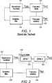
1 stellt einen typischen Frequenzregelkreis dar. Ein steuerbarer Oszillator 101 erzeugt ein Oszillatorsignal mit einer Oszillatorsignalfrequenz FOSC. Ein Frequenzteiler 102 dividiert die Oszillatorsignalfrequenz auf einen Wert FOUT herunter, der zum Takten einer Schaltungsanordnung am Ausgang des Frequenzregelkreises geeignet ist. Ein Frequenzdetektor 104 vergleicht FOUT mit einer Referenzfrequenz FREF und gibt ein Signal aus, das das Verhältnis dieser zwei Frequenzen darstellt. Ein Schleifenfilter 106 filtert die Ausgabe des Frequenzdetektors. Die Ausgabe des Schleifenfilters 106 ist ein Steuersignal, das in den Oszillator 101 eingegeben wird, um die Frequenz FOSC des Oszillatorsignals zu steuern, das vom Oszillator 101 erzeugt wird. 1 represents a typical frequency locked loop. A controllable oscillator 101 generates an oscillator signal with an oscillator signal frequency F OSC . A frequency divider 102 divides the oscillator signal frequency down to a value F OUT suitable for clocking a circuit at the output of the frequency locked loop. A frequency detector 104 compares F OUT with a reference frequency F REF and outputs a signal representing the ratio of these two frequencies. A loop filter 106 filters the output of the frequency detector. The output of the loop filter 106 is a control signal that is in the oscillator 101 is input to control the frequency F OSC of the oscillator signal supplied by the oscillator 101 is produced.
Es ist bekannt, den Frequenzteiler, den Frequenzdetektor und das Schleifenfilter eines Frequenzregelkreises digital zu implementieren. Dies ermöglicht eine größere Anpassungsfähigkeit an die Schaltungsanordnung am Ausgang des Frequenzregelkreises als in Phasenregelkreisen. Der Durchlassbereich des Schleifenfilters kann beispielsweise verringert werden, wenn das Referenzsignal instabil ist. Alternativ kann der Durchlassbereich des Schleifenfilters verbreitert werden, wenn es erwünscht ist, dass der Frequenzregelkreis die Frequenz des Oszillatorsignals schnell an Änderungen im Referenzsignal anpasst. Als weiteres Beispiel kann der Frequenzdetektor dazu programmiert sein, verschiedene Frequenzverhältnisse zu handhaben, wenn sich FREF aufgrund dessen, dass die Ausgabeschaltungsanordnung in einen anderen Modus wechselt oder in diesem arbeitet, ändert.It is known to digitally implement the frequency divider, the frequency detector and the loop filter of a frequency locked loop. This allows a greater adaptability to the circuitry at the output of the frequency locked loop than in phase locked loops. For example, the passband of the loop filter may be reduced if the reference signal is unstable. Alternatively, the passband of the loop filter may be widened if it is desired that the frequency-locked loop rapidly adjusts the frequency of the oscillator signal to changes in the reference signal. As another example, the frequency detector may be programmed to handle different frequency ratios when F REF changes due to the output circuitry changing to or operating in another mode.
Es ist bekannt, den Frequenzteiler 102 unter Verwendung eines synchronen Zählers zu implementieren. Ein typischer synchroner Zähler umfasst eine Reihe von Registern, die mit Logik durchsetzt sind. Typischerweise gibt jede Logikstufe des synchronen Zählers ein Signal mit der halben Frequenz des in ihn eingegebenen Signals aus. Wenn FOUT um Größenordnungen kleiner ist als FOSC, sind viele Logikzustände erforderlich. Dies verbraucht viel Leistung.It is known the frequency divider 102 using a synchronous counter. A typical synchronous counter comprises a series of registers interspersed with logic. Typically, each logic stage of the synchronous counter outputs a signal at half the frequency of the signal input thereto. If F OUT is orders of magnitude smaller than F OSC , many logic states are required. This consumes a lot of power.
Mit erhöhtem Marktbedarf an elektronischen Vorrichtungen mit niedrigerer Leistung/längerer Batterielebensdauer ist eine leistungsärmere Implementierung des Frequenzregelkreises erforderlich. Außerdem besteht ein Bedarf, die Genauigkeit und Stabilität des durch den Oszillator erzeugten Taktsignals zu verbessern.With increased market demand for lower power / longer battery life electronic devices, a lower power implementation of the frequency locked loop is required. In addition, there is a need to improve the accuracy and stability of the clock signal generated by the oscillator.
KURZFASSUNG DER ERFINDUNGSUMMARY OF THE INVENTION
Gemäß einem ersten Aspekt wird ein Verfahren zum Abschätzen einer Oszillatorsignalfrequenz geschaffen, das umfasst: Erzeugen eines Oszillatorsignals mit der Oszillatorsignalfrequenz; Takten einer Logik mit dem Oszillatorsignal; an der Logik, Reagieren auf einen Taktimpuls durch Vorschieben eines Zustandes in einem vorbestimmten Zyklus von Zuständen; Messen des Zustandes der Logik an beiden Grenzen eines ersten Zeitintervalls; Bestimmen einer Abschätzung der Oszillatorsignalfrequenz aus einer bestimmten Anzahl von abgelaufenen Zuständen der Logik im ersten Zeitintervall; Messen des Zustandes der Logik an beiden Grenzen eines zweiten Zeitintervalls, wobei das zweite Zeitintervall länger ist als das erste Zeitintervall; und Bestimmen einer verfeinerten Abschätzung der Oszillatorsignalfrequenz aus einer bestimmten Anzahl von abgelaufenen Zuständen der Logik im zweiten Zeitintervall.According to a first aspect, there is provided a method of estimating an oscillator signal frequency, comprising: generating an oscillator signal having the oscillator signal frequency; Clocking a logic with the oscillator signal; at the logic, responding to a clock pulse by advancing a state in a predetermined cycle of states; Measuring the state of the logic at both boundaries of a first time interval; Determining an estimate of the oscillator signal frequency from a predetermined number of elapsed states of the logic in the first time interval; Measuring the state of the logic at both boundaries of a second time interval, the second time interval being longer than the first time interval; and determining a refined estimate of the oscillator signal frequency from a predetermined number of elapsed states of the logic in the second time interval.
Geeigneterweise umfasst das Verfahren das Bestimmen der Anzahl von abgelaufenen Zuständen der Logik im zweiten Zeitintervall durch Bestimmen von Kandidatenanzahlen von abgelaufenen Zuständen, wobei jede Kandidatenanzahl von abgelaufenen Zuständen auf einer unterschiedlichen Anzahl von Umläufen des vorbestimmten Zyklus von Zuständen während des zweiten Zeitintervalls basiert.Suitably, the method includes determining the number of elapsed states of the logic in the second time interval by determining candidate numbers of elapsed states, wherein each candidate number of elapsed states is based on a different number of round trips of the predetermined cycle of states during the second time interval.
Geeigneterweise wird mindestens eine Kandidatenanzahl von abgelaufenen Zuständen auf der Basis der Abschätzung der Oszillatorsignalfrequenz verworfen.Suitably, at least one candidate number of elapsed states is discarded based on the estimate of the oscillator signal frequency.
Geeigneterweise ist die Abschätzung der Oszillatorsignalfrequenz ein Frequenzbereich und das Verfahren umfasst das Verwerfen von Kandidatenanzahlen von abgelaufenen Zuständen, die dazu führen würden, dass die verfeinerte Abschätzung nicht innerhalb des Frequenzbereichs eingeschlossen ist. Suitably, the estimate of the oscillator signal frequency is a frequency range and the method comprises discarding candidate numbers of elapsed states that would result in the refined estimate not being included within the frequency range.
Geeigneterweise ist die Abschätzung der Oszillatorsignalfrequenz ein Frequenzbereich und das Verfahren umfasst das Auswählen einer Kandidatenanzahl von abgelaufenen Zuständen als die bestimmte Anzahl von abgelaufenen Zuständen der Logik im zweiten Zeitintervall nur dann, wenn diese Kandidatenanzahl von abgelaufenen Zuständen dazu führen würde, dass die verfeinerte Abschätzung innerhalb des Frequenzbereichs eingeschlossen ist.Suitably, the estimate of the oscillator signal frequency is a frequency range and the method comprises selecting a candidate number of elapsed states as the determined number of elapsed states of the logic in the second time interval only if that candidate number of elapsed states would cause the refined estimate to be within the Frequency range is included.
Geeigneterweise umfasst das Verfahren ferner: Messen des Zustandes der Logik an beiden Grenzen eines dritten Zeitintervalls, wobei das dritte Zeitintervall länger ist als das zweite Zeitintervall; Bestimmen einer weiteren verfeinerten Abschätzung der Oszillatorsignalfrequenz aus einer bestimmten Anzahl von abgelaufenen Zuständen der Logik im dritten Zeitintervall.Suitably, the method further comprises: measuring the state of the logic at both boundaries of a third time interval, wherein the third time interval is longer than the second time interval; Determining a further refined estimate of the oscillator signal frequency from a predetermined number of elapsed states of the logic in the third time interval.
Geeigneterweise umfasst das Verfahren das Bestimmen der Anzahl von abgelaufenen Zuständen der Logik im dritten Zeitintervall durch Bestimmen von Kandidatenanzahlen von abgelaufenen Zuständen, wobei jede Kandidatenanzahl von abgelaufenen Zuständen auf einer unterschiedlichen Anzahl von Umläufen des vorbestimmten Zyklus von Zuständen während des dritten Zeitintervalls basiert.Suitably, the method includes determining the number of elapsed states of the logic in the third time interval by determining candidate numbers of elapsed states, wherein each candidate number of elapsed states is based on a different number of cycles of the predetermined cycle of states during the third time interval.
Geeigneterweise ist die verfeinerte Abschätzung der Oszillatorsignalfrequenz ein verfeinerter Frequenzbereich, und das Verfahren umfasst das Verwerfen von Kandidatenanzahlen von abgelaufenen Zuständen, die dazu führen würden, dass die weiter verfeinerte Abschätzung nicht innerhalb des verfeinerten Frequenzbereichs eingeschlossen ist.Suitably, the refined estimate of the oscillator signal frequency is a refined frequency range, and the method comprises discarding candidate numbers of elapsed states that would result in the further refined estimate not being included within the refined frequency range.
Geeigneterweise ist die verfeinerte Abschätzung der Oszillatorsignalfrequenz ein verfeinerter Frequenzbereich, und das Verfahren umfasst das Auswählen einer Kandidatenanzahl von abgelaufenen Zuständen als die bestimmte Anzahl von abgelaufenen Zuständen der Logik im dritten Zeitintervall nur dann, wenn diese Kandidatenanzahl dazu führen würde, dass die weiter verfeinerte Abschätzung innerhalb des verfeinerten Frequenzbereichs eingeschlossen ist.Suitably, the refined estimate of the oscillator signal frequency is a refined frequency range, and the method comprises selecting a candidate number of elapsed states as the determined number of elapsed states of the logic in the third time interval only if that candidate number would result in the further refined estimate within of the refined frequency range is included.
Geeigneterweise umfasst die Logik einen ersten Zähler und einen zweiten Zähler, und das Verfahren umfasst: Takten des ersten Zählers mit dem Oszillatorsignal; am ersten Zähler, Erzeugen eines Ausgangssignals des ersten Zählers; und Takten des zweiten Zählers mit dem Ausgangssignal des ersten Zählers; wobei der Zustand der Logik ein kombinierter Zustand des ersten Zählers und Zustand des zweiten Zählers ist.Suitably, the logic comprises a first counter and a second counter, and the method comprises: clocking the first counter with the oscillator signal; at the first counter, generating an output of the first counter; and clocking the second counter with the output of the first counter; wherein the state of the logic is a combined state of the first counter and state of the second counter.
Geeigneterweise ändert das Ausgangssignal des ersten Zählers den Zustand mit einem Bruchteil der Oszillatorsignalfrequenz, so dass der zweite Zähler mit dem Bruchteil der Oszillatorsignalfrequenz getaktet wird.Suitably, the output of the first counter changes the state at a fraction of the oscillator signal frequency, such that the second counter is clocked at the fraction of the oscillator signal frequency.
Geeigneterweise umfasst das Verfahren das Messen des Zustandes der Logik durch: Messen des Zustandes des ersten Zählers; Bestimmen einer Zeit, zu der der Zustand des zweiten Zählers gemessen werden soll, in Abhängigkeit vom Zustand des ersten Zählers; und Messen des Zustandes des zweiten Zählers zur bestimmten Zeit.Suitably, the method comprises measuring the state of the logic by: measuring the state of the first counter; Determining a time at which the state of the second counter is to be measured in dependence on the state of the first counter; and measuring the state of the second counter at the predetermined time.
Wenn der gemessene Zustand des ersten Zählers darauf hinweist, dass das Ausgangssignal des ersten Zählers in Reaktion auf den jüngsten Taktimpuls, der vom ersten Zähler empfangen wird, den Zustand geändert hat, umfasst das Verfahren geeigneterweise das Auswählen der bestimmten Zeit als ein vorbestimmtes Intervall nach der Messung des Zustandes des ersten Zählers.When the measured state of the first counter indicates that the output of the first counter has changed state in response to the most recent clock pulse received from the first counter, the method suitably includes selecting the particular time as a predetermined interval after Measurement of the state of the first counter.
Geeigneterweise umfasst das Verfahren ferner das Vorhersagen der Anzahl von abgelaufenen Zuständen der Logik im zweiten Zeitintervall in Abhängigkeit von der bestimmten Anzahl von abgelaufenen Zuständen der Logik im ersten Zeitintervall.Suitably, the method further comprises predicting the number of expired states of the logic in the second time interval depending on the determined number of expired states of the logic in the first time interval.
Geeigneterweise umfasst das Verfahren ferner: Vergleichen der bestimmten Anzahl von abgelaufenen Zuständen der Logik im zweiten Zeitintervall mit der vorhergesagten Anzahl von abgelaufenen Zuständen der Logik im zweiten Zeitintervall; und wenn die bestimmte Anzahl von abgelaufenen Zuständen der Logik im zweiten Zeitintervall und die vorhergesagte Anzahl von abgelaufenen Zuständen der Logik im zweiten Zeitintervall unterschiedlich sind, Detektieren eines Fehlers in der bestimmten Anzahl von abgelaufenen Zuständen der Logik im zweiten Zeitintervall unter Verwendung eines Trellisnetzes.Suitably, the method further comprises: comparing the determined number of expired states of the logic in the second time interval with the predicted number of expired states of the logic in the second time interval; and if the determined number of expired states of the logic in the second time interval and the predicted number of expired states of the logic in the second time interval are different, detecting an error in the determined number of expired states of the logic in the second time interval using a trellis network.
Geeigneterweise umfasst das Verfahren ferner: Vorhersagen der Anzahl von abgelaufenen Zuständen der Logik im dritten Zeitintervall in Abhängigkeit von der bestimmten Anzahl von abgelaufenen Zuständen der Logik im ersten Zeitintervall und von der bestimmten Anzahl von abgelaufenen Zuständen der Logik im zweiten Zeitintervall; Vergleichen der bestimmten Anzahl von abgelaufenen Zuständen der Logik im dritten Zeitintervall mit der vorhergesagten Anzahl von abgelaufenen Zuständen der Logik im dritten Zeitintervall; und wenn die bestimmte Anzahl von abgelaufenen Zuständen der Logik im dritten Zeitintervall und die vorhergesagte Anzahl von abgelaufenen Zuständen der Logik im dritten Zeitintervall unterschiedlich sind, Detektieren eines Fehlers in einer oder beiden der bestimmten Anzahl von abgelaufenen Zuständen der Logik im zweiten Zeitintervall und der bestimmten Anzahl von abgelaufenen Zuständen der Logik im dritten Zeitintervall unter Verwendung eines Trellisnetzes.Suitably, the method further comprises: predicting the number of expired states of the logic in the third time interval depending on the determined number of expired states of the logic in the first time interval and on the determined number of expired states of the logic in the second Time interval; Comparing the determined number of elapsed states of the logic in the third time interval with the predicted number of elapsed states of the logic in the third time interval; and if the determined number of expired states of the logic in the third time interval and the predicted number of expired states of the logic in the third time interval are different, detecting an error in one or both of the determined number of expired states of the logic in the second time interval and the determined number of elapsed states of the logic in the third time interval using a trellis network.
Gemäß einem zweiten Aspekt wird ein Frequenzregelkreis zum Erzeugen eines Taktsignals geschaffen, der umfasst: einen steuerbaren Oszillator, der dazu ausgelegt ist, in Abhängigkeit von einem Steuersignal ein Oszillatorsignal mit einer Oszillatorsignalfrequenz zu erzeugen; einen Frequenzteiler, der mit dem steuerbaren Oszillator gekoppelt ist und dazu ausgelegt ist, die Oszillatorsignalfrequenz zu verringern, um eine dividierte Oszillatorsignalfrequenz zu bilden; und einen Frequenzdetektor, der mit dem Frequenzteiler gekoppelt ist und dazu ausgelegt ist, das Steuersignal in Abhängigkeit von einer Referenzsignalfrequenz zu erzeugen; wobei der Frequenzteiler einen ersten Zähler und einen zweiten Zähler umfasst, wobei der erste Zähler dazu ausgelegt ist, durch das Oszillatorsignal getaktet zu werden und ein Ausgangssignal des ersten Zählers zu erzeugen, und der zweite Zähler dazu ausgelegt ist, durch das Ausgangssignal des ersten Zählers getaktet zu werden.According to a second aspect, there is provided a frequency locked loop for generating a clock signal, comprising: a controllable oscillator configured to generate an oscillator signal having an oscillator signal frequency in response to a control signal; a frequency divider coupled to the controllable oscillator and configured to reduce the oscillator signal frequency to form a divided oscillator signal frequency; and a frequency detector coupled to the frequency divider and configured to generate the control signal in response to a reference signal frequency; wherein the frequency divider comprises a first counter and a second counter, the first counter being adapted to be clocked by the oscillator signal and to generate an output signal of the first counter, and the second counter is adapted to be clocked by the output signal of the first counter to become.
Geeigneterweise ist der erste Zähler ein verdrehter Ringzähler.Suitably, the first counter is a rotated ring counter.
Geeigneterweise ist der zweite Zähler ein Schieberegister mit linearer Rückkopplung.Suitably, the second counter is a linear feedback shift register.
Geeigneterweise umfasst der Frequenzdetektor: ein erstes Zustandsregister für den ersten Zähler; und ein zweites Zustandsregister für den zweiten Zähler; wobei der Frequenzdetektor dazu ausgelegt ist, den Zustand des Frequenzteilers durch Messen des Zustandes des ersten Zählers am ersten Zustandsregister und Messen des Zustandes des zweiten Zählers am zweiten Zustandsregister zu bestimmen, und der Frequenzdetektor dazu ausgelegt ist, das Steuersignal in Abhängigkeit vom Zustand des Frequenzteilers zu erzeugen.Suitably, the frequency detector comprises: a first state register for the first counter; and a second status register for the second counter; wherein the frequency detector is adapted to determine the state of the frequency divider by measuring the state of the first counter at the first state register and measuring the state of the second counter at the second state register, and the frequency detector is adapted to supply the control signal in dependence on the state of the frequency divider produce.
KURZBESCHREIBUNG DER FIGURENBRIEF DESCRIPTION OF THE FIGURES
Die vorliegende Offenbarung wird nun beispielhaft mit Bezug auf die begleitenden Zeichnungen beschrieben. In den Zeichnungen gilt:The present disclosure will now be described by way of example with reference to the accompanying drawings. In the drawings:
1 stellt einen typischen Frequenzregelkreis dar; 1 represents a typical frequency locked loop;
2 stellt einen Frequenzregelkreis mit zwei Zählern dar; 2 represents a frequency control circuit with two counters;
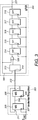
3 stellt eine Implementierung des Frequenzteilers von 2 mit einem verdrehten Ringzähler und einem Schieberegister mit linearer Rückkopplung dar; 3 represents an implementation of the frequency divider of 2 with a twisted ring counter and a shift register with linear feedback;
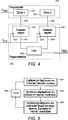
4 stellt eine Implementierung des Frequenzdetektors von 2 dar; 4 represents an implementation of the frequency detector of 2 group;
5 ist ein Flussdiagramm, das ein Verfahren zum Abschätzen der Frequenz des Oszillatorsignals darstellt; 5 FIG. 10 is a flowchart illustrating a method of estimating the frequency of the oscillator signal; FIG.
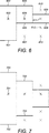
6 stellt ein binäres Zerhackverfahren zum Implementieren des Flussdiagramms von 5 dar; 6 illustrates a binary chopping method for implementing the flowchart of FIG 5 group;
7 stellt ein weiteres binäres Zerhackverfahren zum Implementieren des Flussdiagramms von 5 dar; und 7 illustrates another binary chopping method for implementing the flowchart of FIG 5 group; and
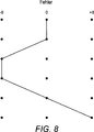
8 stellt ein Trellisnetz dar. 8th represents a trellis net.
AUSFÜHRLICHE BESCHREIBUNGDETAILED DESCRIPTION
Die folgende Beschreibung wird als Beispiel dargestellt, um irgendeinem Fachmann auf dem Gebiet zu ermöglichen, die Erfindung herzustellen und zu verwenden. Die Erfindung ist nicht auf die hier beschriebenen Beispiele begrenzt und verschiedene Modifikationen an den offenbarten Beispielen sind für den Fachmann auf dem Gebiet leicht ersichtlich.The following description is presented by way of example to enable any person skilled in the art to make and use the invention. The invention is not limited to the examples described herein, and various modifications to the disclosed examples will be readily apparent to those skilled in the art.
2 ist eine schematische Darstellung eines Frequenzregelkreises. 3 ist eine schematische Darstellung einer Implementierung des Zählers 1 und des Zählers 2 aus 2. 4 ist eine schematische Darstellung einer Implementierung des Frequenzteilers und des Frequenzdetektors aus 2. Diese Figuren stellen einige Komponenten des Frequenzregelkreises hinsichtlich Funktionsblöcken dar. Einige Funktionsblöcke zum Ausführen von Funktionen, die auf dem Fachgebiet gut bekannt sind, wurden stellenweise aus diesen Figuren weggelassen. Funktionsblöcke, die beispielsweise Analog-Digital-Umsetzer darstellen, wurden aus diesen Figuren weggelassen. 2 is a schematic representation of a frequency control loop. 3 is a schematic representation of an implementation of the counter 1 and the counter 2 from 2 , 4 is a schematic representation of an implementation of the frequency divider and the frequency detector 2 , These figures represent some components of the frequency locked loop in terms of functional blocks. Some functional blocks for performing functions well known in the art have been omitted in some instances from these figures. Function blocks representing, for example, analog-to-digital converters have been omitted from these figures.
5 ist ein Flussdiagramm, das ein Verfahren zum Abschätzen der Frequenz eines Oszillatorsignals darstellt. Dieses Flussdiagramm stellt eine Reihenfolge dar, in der das Verfahren des Flussdiagramms durchgeführt werden kann. Das Flussdiagramm soll jedoch das beschriebene Verfahren nicht darauf einschränken, dass es in der dargestellten Reihenfolge implementiert wird. Die Schritte des Verfahrens können in einer alternativen Reihenfolge zu der im Flussdiagramm dargestellten ausgeführt werden. 5 FIG. 10 is a flowchart illustrating a method of estimating the frequency of an oscillator signal. FIG. This flowchart represents an order in which the method of the flowchart can be performed. However, the flowchart is not intended to limit the described method to being implemented in the order shown. The steps of the method may be performed in an alternate order to that illustrated in the flowchart.
2 ist eine schematische Darstellung, die die allgemeine Anordnung eines Frequenzregelkreises darstellt. Ein steuerbarer Oszillator 201 ist mit einem Frequenzteiler 202 verbunden. Der Frequenzteiler umfasst einen Zähler 1 203 und einen Zähler 2 204. Der Zähler 1 empfängt die Ausgabe des steuerbaren Oszillators 201 als Eingabe. Der Zähler 2 empfängt die Ausgabe des Zählers 1 als Eingabe. Die Ausgabe des Zählers 2 wird aus dem Frequenzregelkreis ausgegeben. Der Frequenzdetektor 205 ist mit dem Frequenzteiler 202 verbunden. Der Frequenzdetektor 205 empfängt als Eingaben eine Ausgabe vom Frequenzteiler 202 und ein Referenzsignal mit einer Frequenz FREF. Der Frequenzdetektor 205 ist mit einem Schleifenfilter 206 verbunden. Das Schleifenfilter 206 empfängt als Eingabe die Ausgabe des Frequenzdetektors 205. Die Ausgabe des Schleifenfilters 206 ist ein Steuersignal, das den steuerbaren Oszillator 201 steuert. 2 is a schematic representation illustrating the general arrangement of a frequency control loop. A controllable oscillator 201 is with a frequency divider 202 connected. The frequency divider comprises a counter 1 203 and a counter 2 204 , The counter 1 receives the output of the controllable oscillator 201 as input. The counter 2 receives the output of the counter 1 as input. The output of the counter 2 is output from the frequency-locked loop. The frequency detector 205 is with the frequency divider 202 connected. The frequency detector 205 receives as inputs an output from the frequency divider 202 and a reference signal having a frequency F REF . The frequency detector 205 is with a loop filter 206 connected. The loop filter 206 receives as input the output of the frequency detector 205 , The output of the loop filter 206 is a control signal that is the controllable oscillator 201 controls.
Im Betrieb erzeugt der steuerbare Oszillator 201 ein Oszillatorsignal mit einer Oszillatorsignalfrequenz FOSC. Der Frequenzteiler 202 transformiert das Oszillatorsignal, um ein Taktsignal zu bilden. Der Frequenzteiler 202 dividiert die Oszillatorsignalfrequenz FOSC auf eine dividierte Oszillatorsignalfrequenz FOUT, so dass das durch den Frequenzregelkreis aus dem Frequenzteiler 202 ausgegebene Taktsignal eine Frequenz FOUT aufweist. Der Frequenzteiler 202 dividiert die Oszillatorsignalfrequenz in zwei Stufen: die erste Stufe verwendet den Zähler 1 und die zweite Stufe verwendet den Zähler 2.In operation, the controllable oscillator generates 201 an oscillator signal having an oscillator signal frequency F OSC . The frequency divider 202 transforms the oscillator signal to form a clock signal. The frequency divider 202 divides the oscillator signal frequency F OSC to a divided oscillator signal frequency F OUT , so that by the frequency locked loop from the frequency divider 202 output clock signal has a frequency F OUT . The frequency divider 202 divides the oscillator signal frequency into two stages: the first stage uses counter 1 and the second stage uses counter 2.
Der Zähler 1 wird durch das Oszillatorsignal getaktet. Jedes Mal, wenn das Oszillatorsignal den Zustand ändert, ändert der Zähler 1 geeigneterweise den Zustand. Mit anderen Worten, jeder Übergang von 0 auf 1 und 1 auf 0 des Taktsignals, das vom Oszillator 201 empfangen wird, verursacht, dass der Zähler 1 den Zustand ändert. Somit ändert der Zähler 1 den Zustand bei sowohl der steigenden Flanke als auch der fallenden Flanke des Taktsignals, das vom Oszillator 201 empfangen wird. Der Zustand des Zählers 1 schreitet in einer vorbestimmten Weise voran. Der Zähler 1 weist beispielsweise eine vorbestimmte Sequenz von Zuständen auf, die er in einer vorbestimmten Reihenfolge durchschreitet. Geeigneterweise schreitet der Zähler 1 bei jeder Taktflanke des vom Oszillator 201 empfangenen Taktsignals einen Zustand in der vorbestimmten Sequenz von Zuständen voran. Die vorbestimmte Sequenz von Zuständen umfasst eine begrenzte Anzahl von unterschiedlichen Zuständen. Sobald der Zähler 1 die unterschiedlichen Zustände durchschritten hat, kehrt er geeigneterweise zu einem Zustand zurück, den er vorher gehalten hat, und durchschreitet erneut die unterschiedlichen Zustände. Wenn beispielsweise die vorbestimmte Sequenz von Zuständen n, n + 1, n + 2 ... N – 2, N – 1, N ist, dann ist der N + 1-te Zustand n und der N + 2-te Zustand ist n + 1. Ebenso ist der 2N + 1-te Zustand n und der 2N + 2-te Zustand ist n + 1. Folglich läuft der Zähler 1 im Zyklus um die vorbestimmte Sequenz von Zuständen, wobei jeder Zustandsübergang beim Empfang einer Taktflanke stattfindet.The counter 1 is clocked by the oscillator signal. Each time the oscillator signal changes state, the counter 1 suitably changes the state. In other words, every transition from 0 to 1 and 1 to 0 of the clock signal from the oscillator 201 is received causes the counter 1 to change the state. Thus, the counter 1 changes the state at both the rising edge and the falling edge of the clock signal from the oscillator 201 Will be received. The state of the counter 1 proceeds in a predetermined manner. The counter 1 has, for example, a predetermined sequence of states which it traverses in a predetermined order. Suitably, the counter 1 steps on each clock edge of the oscillator 201 received clock signal precedes a state in the predetermined sequence of states. The predetermined sequence of states includes a limited number of different states. As soon as the counter 1 has passed through the different states, it suitably returns to a state which it previously held, and again traverses the different states. For example, if the predetermined sequence of states is n, n + 1, n + 2 ... N-2, N-1, N, then the N + 1th state is n and the N + 2th state is n + 1. Similarly, the 2N + 1th state is n and the 2N + 2th state is n + 1. Consequently, the counter 1 cycles around the predetermined sequence of states, each state transition occurring upon receipt of a clock edge.
Der Zähler 1 gibt ein Signal aus, das den Zustand mit einem Bruchteil der Rate ändert, mit der der Zähler 1 getaktet wird. Mit anderen Worten, das Ausgangssignal des Zählers 1 weist eine Frequenz auf, die ein Bruchteil der Oszillatorsignalfrequenz FOSC ist. Geeigneterweise ist FOSC ein Vielfaches der Frequenz des Ausgangssignals des Zählers 1.The counter 1 outputs a signal which changes the state at a fraction of the rate at which the counter 1 is clocked. In other words, the output of the counter 1 has a frequency which is a fraction of the oscillator signal frequency F OSC . Suitably, F OSC is a multiple of the frequency of the output of counter 1.
Der Zähler 2 wird durch das Ausgangssignal des Zählers 1 getaktet. Folglich wird der Zähler 2 mit einem Bruchteil der Oszillatorsignalfrequenz FOSC getaktet. Jedes Mal, wenn der Zähler 1 durch seine vorbestimmte Sequenz von Zuständen einmal im Zyklus läuft, ändert der Zähler 2 geeigneterweise den Zustand einmal. Mit anderen Worten, der Zähler 2 ändert den Zustand entweder beim Empfang eines Übergangs von 0 auf 1 des Taktsignals, das vom Zähler 1 empfangen wird, oder alternativ beim Empfang eines Übergangs von 1 auf 0 des Taktsignals, das vom Zähler 1 empfangen wird. Somit ändert der Zähler 2 den Zustand bei einer der steigenden Flanke und der fallenden Flanke des Taktsignals, das vom Zähler 1 empfangen wird. Der Zustand des Zählers 2 schreitet in einer vorbestimmten Weise voran. Der Zähler 2 weist beispielsweise eine vorbestimmte Sequenz von Zuständen auf, die er in einer vorbestimmten Reihenfolge durchschreitet. Geeigneterweise schreitet der Zähler 2 während jeder Taktperiode des vom Zähler 1 empfangenen Taktsignals um einen Zustand in der vorbestimmten Sequenz von Zuständen weiter. Die vorbestimmte Sequenz von Zuständen umfasst eine begrenzte Anzahl von unterschiedlichen Zuständen. Sobald der Zähler 2 die unterschiedlichen Zustände durchschritten hat, kehrt er geeigneterweise zu einem Zustand zurück, den er vorher gehalten hat, und durchschreitet die unterschiedlichen Zustände erneut. Wenn beispielsweise die vorbestimmte Sequenz von Zuständen m, m + 1, m + 2 ... M – 2, M – 1, M ist, dann ist der M + 1-te Zustand m und der M + 2-te Zustand ist m + 1. Ebenso ist der 2M + 1-te Zustand m und der 2M + 2-te Zustand ist m + 1. Folglich läuft der Zähler 2 im Zyklus um die vorbestimmte Sequenz von Zuständen, wobei jeder Zustandsübergang beim Empfang entweder der steigenden Taktflanke oder der fallenden Taktflanke stattfindet, in Abhängigkeit davon, wie der Zähler 2 ausgelegt ist.The counter 2 is clocked by the output of the counter 1. Consequently, the counter 2 is clocked at a fraction of the oscillator signal frequency F OSC . Each time the counter 1 times its cycle through its predetermined sequence of states, the counter 2 suitably changes state once. In other words, the counter 2 changes state either upon receipt of a transition from 0 to 1 of the clock signal received from the counter 1 or alternatively upon receipt of a transition from 1 to 0 of the clock signal received from the counter 1. Thus, the counter 2 changes the state at one of the rising edge and the falling edge of the clock signal received from the counter 1. The state of the counter 2 proceeds in a predetermined manner. The counter 2 has, for example, one predetermined sequence of states, which he traverses in a predetermined order. Suitably, during each clock period of the clock signal received from counter 1, counter 2 advances by one state in the predetermined sequence of states. The predetermined sequence of states includes a limited number of different states. As soon as the counter 2 has passed through the different states, it suitably returns to a state which it previously held, and passes through the different states again. For example, if the predetermined sequence of states is m, m + 1, m + 2 ... M-2, M-1, M, then the M + 1th state is m and the M + 2th state is m + 1. Similarly, the 2M + 1th state is m and the 2M + 2th state is m + 1. Consequently, the counter 2 cycles around the predetermined sequence of states, each state transition upon receipt of either the rising clock edge or the falling clock edge occurs, depending on how the counter 2 is designed.
Der Zähler 2 gibt ein Signal aus, das den Zustand mit einem Bruchteil der Rate ändert, mit der der Zähler 2 getaktet wird. Mit anderen Worten, das Ausgangssignal des Zählers 2 weist eine Frequenz auf, die ein Bruchteil der Ausgangssignalfrequenz des Zählers 1 ist. Geeigneterweise ist FOSC ein Vielfaches der Frequenz des Ausgangssignals des Zählers 2.The counter 2 outputs a signal which changes the state at a fraction of the rate at which the counter 2 is clocked. In other words, the output signal of the counter 2 has a frequency which is a fraction of the output signal frequency of the counter 1. Suitably, F OSC is a multiple of the frequency of the output of counter 2.
Der Frequenzdetektor 205 schätzt die Oszillatorsignalfrequenz FOSC ab. Der Frequenzdetektor 205 schätzt FOSC in Abhängigkeit von einer Reihe von gemessenen Zuständen des Frequenzteilers 202 ab. Der gemessene Zustand des Frequenzteilers 202 ist eine Kombination des gemessenen Zustandes des Zählers 1 und des gemessenen Zustandes des Zählers 2. Ein Verfahren zum Abschätzen der Oszillatorsignalfrequenz FOSC wird in Bezug auf 5 genauer beschrieben.The frequency detector 205 estimates the oscillator signal frequency F OSC . The frequency detector 205 estimates F OSC as a function of a number of measured states of the frequency divider 202 from. The measured state of the frequency divider 202 is a combination of the measured state of the counter 1 and the measured state of the counter 2. A method of estimating the oscillator signal frequency F OSC is described with reference to FIG 5 described in more detail.
Der Frequenzdetektor 205 vergleicht auch eine von FOSC abgeleitete Frequenz mit einer Referenzfrequenz FREF und gibt ein Signal aus, das das Verhältnis dieser zwei Frequenzen darstellt. Das Schleifenfilter 206 filtert die Ausgabe des Frequenzdetektors. Die Ausgabe des Schleifenfilters 206 ist ein Steuersignal, das in den Oszillator 201 eingegeben wird, um die Frequenz FOSC des Oszillatorsignals zu steuern, das durch den Oszillator 201 erzeugt wird. Alternativ ist die Ausgabe des Frequenzdetektors 205 das Steuersignal, das in den Oszillator 201 eingegeben wird, um die Frequenz FOSC des Oszillatorsignals zu steuern, das durch den Oszillator 201 erzeugt wird.The frequency detector 205 also compares a frequency derived from F OSC with a reference frequency F REF and outputs a signal representing the ratio of these two frequencies. The loop filter 206 filters the output of the frequency detector. The output of the loop filter 206 is a control signal that is in the oscillator 201 is input to control the frequency F OSC of the oscillator signal generated by the oscillator 201 is produced. Alternatively, the output of the frequency detector 205 the control signal coming into the oscillator 201 is input to control the frequency F OSC of the oscillator signal generated by the oscillator 201 is produced.
3 stellt eine beispielhafte Implementierung des Frequenzteilers 202 von 2 dar. Der Zähler 1 303 ist ein verdrehter Ringzähler. Der Zähler 2 304 ist ein Schieberegister mit linearer Rückkopplung (LFSR). 3 illustrates an exemplary implementation of the frequency divider 202 from 2 dar. The counter 1 303 is a twisted ring counter. The counter 2 304 is a linear feedback shift register (LFSR).
Der verdrehte Ringzähler 303 umfasst zwei Master-Slave-Flip-Flops 305 und 306. Das Master-Slave-Flip-Flop 305 empfängt das Differenz-FOSC-Taktsignal, das aus dem Oszillator 201 ausgegeben wird, am Takteingang 307. Das Master-Slave-Flip-Flop 306 empfängt auch das FOSC-Taktsignal, das aus dem Oszillator 201 ausgegeben wird, am Takteingang 308. Die Ausgabe des Master-Slave-Flip-Flops 305 auf der Leitung 309 wird in das Master-Slave-Flip-Flop 306 eingegeben. Die Ausgabe des Master-Slave-Flip-Flops 306 auf der Leitung 310 wird am Inverter 311 invertiert und dann in das Master-Slave-Flip-Flop 305 eingegeben. Die Ausgabe des Master-Slave-Flip-Flops 306 wird aus dem verdrehten Ringzähler 303 auf der Leitung 312 ausgegeben. Die Verwendung von zwei Master-Slave-Flip-Flops in Reihe, wie in 3 gezeigt, führt zu einer Ausgabe des verdrehten Ringzählers 303, die den Zustand einmal für alle vier Taktflanken des FOSC-Taktsignals ändert. Folglich ändert die Frequenz des aus dem verdrehten Ringzähler ausgegebenen Signals den Zustand mit einem Viertel der Rate des FOSC-Taktsignals Folglich ist die Frequenz des aus dem verdrehten Ringzähler ausgegebenen Signals ¼FOSC. Mit anderen Worten, der verdrehte Ringzähler dividiert die Frequenz des Oszillatorsignals durch einen Faktor von vier.The twisted ring counter 303 includes two master-slave flip-flops 305 and 306 , The master-slave flip-flop 305 receives the difference F OSC clock signal coming from the oscillator 201 is output, at the clock input 307 , The master-slave flip-flop 306 also receives the F OSC clock signal coming from the oscillator 201 is output, at the clock input 308 , The output of the master-slave flip-flop 305 on the line 309 gets into the master-slave flip-flop 306 entered. The output of the master-slave flip-flop 306 on the line 310 is at the inverter 311 inverted and then into the master-slave flip-flop 305 entered. The output of the master-slave flip-flop 306 gets out of the twisted ring counter 303 on the line 312 output. The use of two master-slave flip-flops in series, as in 3 shown results in an output of the twisted ring counter 303 which changes the state once for all four clock edges of the F OSC clock signal. Consequently, the frequency of the signal output from the rotated ring counter changes the state at a quarter of the rate of the F OSC clock signal. Thus, the frequency of the signal output from the rotated ring counter is ¼F OSC . In other words, the twisted ring counter divides the frequency of the oscillator signal by a factor of four.
Das aus dem verdrehten Ringzähler ausgegebenen Signal taktet das LFSR 304. Folglich wird das LFSR 304 mit einem Viertel der Rate getaktet, mit der der verdrehte Ringzähler getaktet wird.The signal output from the rotated ring counter clocks the LFSR 304 , Consequently, the LFSR 304 clocked at a quarter of the rate at which the twisted ring counter is clocked.
Das LFSR 304 umfasst sechs Flip-Flops 313, 314, 315, 316, 317 und 318. Die Flip-Flops sind in Reihe geschaltet. Jedes Flip-Flop empfängt das aus dem verdrehten Ringzähler 312 ausgegebene Signal als Taktsignal an seinem Takteingang. Das Flip-Flop 313 empfängt die Ausgabe 312 des verdrehten Ringzählers am Takteingang 319. Das Flip-Flop 314 empfängt die Ausgabe 312 des verdrehten Ringzählers am Takteingang 320. Das Flip-Flop 315 empfängt die Ausgabe 312 des verdrehten Ringzählers am Takteingang 321. Das Flip-Flop 316 empfängt die Ausgabe 312 des verdrehten Ringzählers am Takteingang 322. Das Flip-Flop 317 empfängt die Ausgabe 312 des verdrehten Ringzählers am Takteingang 323. Das Flip-Flop 318 empfängt die Ausgabe 312 des verdrehten Ringzählers am Takteingang 324. Das erste Flip-Flop in der Reihe, das Flip-Flop 313, empfängt als seine Dateneingabe auf der Leitung 326 die Ausgabe des LFSR, das die Ausgabe des letzten Flip-Flops in der Reihe, des Flip-Flops 318, ist. Die Ausgabe des Flip-Flops 313 wird in ein Exklusiv-Oder-Gatter 325 (XODER) eingegeben. Die andere Eingabe in das XODER-Gatter ist die Ausgabe des LFSR, die die Ausgabe des letzten Flip-Flops in der Reihe, des Flip-Flops 318, ist. Die Ausgabe des XODER-Gatters ist die Eingabe in das nächste Flip-Flop in der Reihe, das Flip-Flop 314. Die Ausgabe des Flip-Flops 314 ist die Eingabe in das nächste Flip-Flop in der Reihe, das Flip-Flop 315. Die Ausgabe des Flip-Flops 315 ist die Eingabe des nächsten Flip-Flops in der Reihe, des Flip-Flops 316. Die Ausgabe des Flip-Flops 316 ist die Eingabe des nächsten Flip-Flops in der Reihe, des Flip-Flops 317. Die Ausgabe des Flip-Flops 317 ist die Eingabe des letzten Flip-Flops in der Reihe, des Flip-Flops 318. Die Ausgabe des Flip-Flops 318 ist die Ausgabe des LFSR. Das XODER-Gatter gibt eine 0 aus, wenn seine zwei Eingaben gleich sind, und gibt eine 1 aus, wenn seine zwei Eingaben unterschiedlich sind.The LFSR 304 includes six flip-flops 313 . 314 . 315 . 316 . 317 and 318 , The flip-flops are connected in series. Each flip-flop receives this from the rotated ring counter 312 output signal as a clock signal at its clock input. The flip-flop 313 receives the output 312 of the twisted ring counter at the clock input 319 , The flip-flop 314 receives the output 312 of the twisted ring counter at the clock input 320 , The flip-flop 315 receives the output 312 of the twisted ring counter at the clock input 321 , The flip-flop 316 receives the output 312 of the twisted ring counter at the clock input 322 , The flip-flop 317 receives the output 312 of the twisted ring counter at the clock input 323 , The flip-flop 318 receives the output 312 of the twisted ring counter at the clock input 324 , The first flip-flop in the series, the flip-flop 313 , receives as its data input on the line 326 the output of the LFSR, which is the output of the last flip-flops in the row, the flip-flops 318 , is. The output of the flip-flop 313 becomes an Exclusive-Or-Gate 325 (XOR) entered. The other input to the XOR gate is the output of the LFSR, which is the output of the last flip-flop in the row, the flip-flop 318 , is. The output of the XOR gate is the input to the next flip-flop in the series, the flip-flop 314 , The output of the flip-flop 314 is the input to the next flip-flop in the series, the flip-flop 315 , The output of the flip-flop 315 is the input of the next flip-flop in the row, the flip-flop 316 , The output of the flip-flop 316 is the input of the next flip-flop in the row, the flip-flop 317 , The output of the flip-flop 317 is the input of the last flip-flop in the row, the flip-flop 318 , The output of the flip-flop 318 is the output of the LFSR. The XOR gate outputs a 0 if its two inputs are equal, and outputs a 1 if its two inputs are different.
3, wie vorstehend beschrieben, stellt eine Konfiguration des verdrehten Ringzählers und eine Konfiguration des LFSR dar. Selbstverständlich sind jedoch andere Konfigurationen des verdrehten Ringzählers und des LFSR möglich. Der verdrehte Ringzähler kann beispielsweise weitere Master-Slave-Flip-Flops umfassen, um die Frequenz des Oszillatorsignals weiter zu verringern. Als weiteres Beispiel kann das LFSR weitere Flip-Flops umfassen, um die Anzahl von Zuständen in der vorbestimmten Sequenz von Zuständen des LFSR und daher die Zeit, die zum Wiederholen der vorbestimmten Zustandssequenz benötigt wird, zu erhöhen. 3 As described above, a configuration of the twisted ring counter and a configuration of the LFSR represents. Of course, however, other configurations of the twisted ring counter and the LFSR are possible. The twisted ring counter may include, for example, further master-slave flip-flops to further reduce the frequency of the oscillator signal. As another example, the LFSR may include additional flip-flops to increase the number of states in the predetermined sequence of states of the LFSR, and therefore the time required to repeat the predetermined state sequence.
Die Verwendung eines verdrehten Ringzählers und eines LFSR als zwei Zähler des Frequenzteilers 202 von 2 ist eine beispielhafte Implementierung. In einem anderen Beispiel ist der Zähler 1 von 2 ein verdrehter Ringzähler und der Zähler 2 von 2 ist ein asynchroner Zähler.The use of a twisted ring counter and an LFSR as two counters of the frequency divider 202 from 2 is an example implementation. In another example, the counter is 1 of 2 a twisted ring counter and the counter 2 of 2 is an asynchronous counter.
Die Verwendung von zwei Zählern, um den Frequenzteiler 202 zu implementieren, von denen einer ein verdrehter Ringzähler ist, spart Leistung relativ zu bekannten Implementierungen, die einen einzelnen synchronen Zähler verwenden. Synchrone Zähler beinhalten eine Logik zwischen jedem Flip-Flop. Diese Logik verbraucht eine relativ große Menge an Leistung. Der verdrehte Ringzähler verringert die Frequenz des Oszillatorsignals um einen Faktor von Vier ohne Verwendung irgendeiner Logik abgesehen vom Inverter 311. Folglich verbraucht der verdrehte Ringzähler weniger Leistung als ein synchroner Zähler. Außerdem führt das nachfolgende LFSR den Rest der Frequenzverringerung durch Arbeiten mit einem Viertel der Geschwindigkeit durch, mit der es arbeiten hätte müssen, wenn es das Oszillatorsignal direkt als Takteingang empfangen hätte. Folglich erfordert das LFSR ein Viertel der Leistung, die es benötigt hätte, wenn es das Oszillatorsignal direkt als Takteingang empfangen hätte. Außerdem sind die Logikstufen zwischen den Flip-Flops des LFSR minimiert, um den Leistungsverbrauch des LFSR zu verringern. Diese Lösung mit zwei Zählern spart folglich Leistung.The use of two counters to the frequency divider 202 one of which is a twisted ring counter, saves performance relative to known implementations that use a single synchronous counter. Synchronous counters include logic between each flip-flop. This logic consumes a relatively large amount of power. The twisted ring counter reduces the frequency of the oscillator signal by a factor of four without using any logic other than the inverter 311 , As a result, the twisted ring counter consumes less power than a synchronous counter. In addition, the subsequent LFSR performs the remainder of the frequency reduction by operating at a quarter of the speed it would have had to work if it had received the oscillator signal directly as a clock input. Consequently, the LFSR requires a quarter of the power it would have needed if it had received the oscillator signal directly as a clock input. In addition, the logic levels between the LFSR flip-flops are minimized to reduce the power consumption of the LFSR. This two-counter solution therefore saves performance.
Jedes Master-Slave-Flip-Flop des verdrehten Ringzählers 303 umfasst zwei Zwischenspeicher in Reihe (Master und Slave). Jeder der Master-Zwischenspeicher ändert den Zustand bei einer Taktflanke des empfangenen Oszillatorsignals. Die Slave-Zwischenspeicher ändern den Zustand bei der anderen Taktflanke des empfangenen Oszillatorsignals. Der Zustand des verdrehten Ringzählers 303 ist die Kombination von Zuständen seiner vier Bestandteilszwischenspeicher. Der Zustand jedes Zwischenspeichers des verdrehten Ringzählers 303 hängt von den Zuständen der anderen Zwischenspeicher des verdrehten Ringzählers 303 ab. Die Weise, in der der Zustand jedes Zwischenspeichers voranschreitet, ist deterministisch. Folglich schreitet der Zustand des verdrehten Ringzählers als Ganzes in einer vorbestimmten Weise voran. Der verdrehte Ringzähler 303, der in 3 gezeigt ist, weist eine Sequenz von acht unterschiedlichen Zuständen auf, die er im Zyklus durchläuft. Sobald er durch diese acht Zustände der Reihe nach fortgeschritten ist, durchläuft er im Zyklus die acht Zustände erneut in derselben Reihenfolge. Mit anderen Worten, der neunte Zustand ist derselbe wie der erste Zustand. Der siebzehnte Zustand ist derselbe wie der erste Zustand.Each master-slave flip-flop of the twisted ring counter 303 includes two buffers in series (master and slave). Each of the master latches changes state at a clock edge of the received oscillator signal. The slave latches change the state at the other clock edge of the received oscillator signal. The state of the twisted ring counter 303 is the combination of states of its four component caches. The state of each cache of the twisted ring counter 303 depends on the states of the other buffers of the twisted ring counter 303 from. The manner in which the state of each cache progresses is deterministic. As a result, the state of the twisted ring counter as a whole proceeds in a predetermined manner. The twisted ring counter 303 who in 3 is shown has a sequence of eight different states that it cycles through. Once he has progressed through these eight states in turn, he cycles through the eight states again in the same order. In other words, the ninth state is the same as the first state. The seventeenth state is the same as the first state.
Jedes Flip-Flop des LFSR 304 ändert den Zustand bei jeder Taktflanke des aus dem verdrehten Ringzähler 303 ausgegebenen Signals. Der Zustand des LFSR ist die Kombination von Zuständen seiner sechs Bestandteils-Flip-Flops. Der Zustand jedes Flip-Flops des LFSR hängt von den Zuständen der anderen Flip-Flops des LFSR ab. Die Weise, in der der Zustand jedes Flip-Flops voranschreitet, ist deterministisch. Folglich schreitet der Zustand des LFSR als Ganzes in einer vorbestimmten Weise voran. Das in 3 gezeigte LFSR weist eine Sequenz von 63 unterschiedlichen Zuständen auf, die es im Zyklus durchläuft. Sobald es durch diese 63 Zustände der Reihe nach fortgeschritten ist, durchläuft es im Zyklus die 63 Zustände erneut in derselben Reihenfolge. Mit anderen Worten, der 64. Zustand ist derselbe wie der erste Zustand. Der 127. Zustand ist derselbe wie der erste Zustand. Der LFSR-Zustand, in dem jedes Flip-Flop sich im gleichen Logikzustand 0 befindet, ist ein illegaler Zustand, der nicht in den vorstehend erwähnten 63 unterschiedlichen Zuständen enthalten ist. Eine zusätzliche Logik ist in das in 3 gezeigte LFSR integriert, um zu vermeiden, dass durch das LFSR in diesen Zustand eingetreten wird.Every flip-flop of the LFSR 304 changes the state at each clock edge of the out of the rotated ring counter 303 output signal. The state of the LFSR is the combination of states of its six constituent flip-flops. The state of each flip-flop of the LFSR depends on the states of the other flip-flops of the LFSR. The manner in which the state of each flip-flop proceeds is deterministic. As a result, the state of the LFSR as a whole proceeds in a predetermined manner. This in 3 The LFSR shown has a sequence of 63 different states that it cycles through. Once it has progressed through these 63 states in turn, it cycles through the 63 states again in the same order. In other words, the 64th state is the same as the first state. The 127th state is the same as the first state. The LFSR state in which each flip-flop is in the same logic state 0 is an illegal state that is not included in the aforementioned 63 different states. An additional logic is in the in 3 integrated LFSR integrated to avoid that is entered by the LFSR in this state.
Der Zustand des Frequenzteilers 202 ist eine Kombination der Zustände des verdrehten Ringzählers 303 und des LFSR 304. Folglich weist der Frequenzteiler 202 8 × 63 = 504 Zustände auf. Der Zustand des Frequenzteilers als Ganzes ändert sich bei jeder Taktflanke des Oszillatorsignals. Folglich ändert sich der Zustand des Frequenzteilers als Ganzes in jedem halben Taktzyklus, mit dem er durch das Oszillatorsignal getaktet wird. Die Weise, in der der Zustand des Frequenzteilers voranschreitet, ist deterministisch. Der Zustand des Frequenzteilers schreitet in einer vorbestimmten Weise durch eine Sequenz von 504 Zuständen fort. Sobald er durch diese 504 Zustände der Reihe nach fortgeschritten ist, durchläuft er die 504 Zustände erneut im Zyklus in derselben Reihenfolge. The state of the frequency divider 202 is a combination of the states of the twisted ring counter 303 and the LFSR 304 , Consequently, the frequency divider is facing 202 8 × 63 = 504 states. The state of the frequency divider as a whole changes at each clock edge of the oscillator signal. Consequently, the state of the frequency divider as a whole changes every half clock cycle with which it is clocked by the oscillator signal. The way in which the state of the frequency divider progresses is deterministic. The state of the frequency divider proceeds in a predetermined manner through a sequence of 504 states. Once he has progressed through these 504 states in turn, he cycles through the 504 states again in the cycle in the same order.
4 stellt eine beispielhafte Implementierung des Frequenzdetektors 205 von 2 dar. Der Frequenzdetektor 205 umfasst zwei Zustandsregister 401, 402. Das Zustandsregister 401 empfängt den Zustand des Zählers 1 als Eingabe auf der Leitung 405. Das Zustandsregister 402 empfängt den Zustand des Zählers 2 als Eingabe auf der Leitung 406. Das Zustandsregister 401 wird durch ein Taktsignal FCLK getaktet, das in den Takteingang 403 eingegeben wird. Das Zustandsregister 402 wird durch dasselbe Taktsignal FCLK getaktet, das in den Takteingang 404 eingegeben wird. Geeigneterweise weist das Taktsignal eine sehr stabile Frequenz auf. Das Taktsignal kann beispielsweise von einem Kristalloszillator abgeleitet sein. Das Zustandsregister 401 gibt den Zustand des Zählers 1 auf der Leitung 407 an die Logik 409 aus. Das Zustandsregister 402 gibt den Zustand des Zählers 2 auf der Leitung 408 an die Logik 409 aus. Die Logik 409 verwendet den gemessenen Zustand des Zählers 1 und den gemessenen Zustand des Zählers 2, um den Zustand des Frequenzteilers zu bestimmen. Die Logik 409 verwendet den Zustand des Frequenzteilers, um die Frequenz des Oszillatorsignals FOSC genau zu bestimmen. Die Logik 409 vergleicht dann die Frequenz des Oszillatorsignals FOSC mit einer Referenzsignalfrequenz FREF und erzeugt ein Steuersignal in Abhängigkeit von diesem Vergleich, um den Oszillator zu steuern. 4 FIG. 3 illustrates an exemplary implementation of the frequency detector 205 from 2 dar. The frequency detector 205 includes two state registers 401 . 402 , The status register 401 receives the state of the counter 1 as input on the line 405 , The status register 402 receives the state of the counter 2 as input on the line 406 , The status register 401 is clocked by a clock signal F CLK which enters the clock input 403 is entered. The status register 402 is clocked by the same clock signal F CLK which enters the clock input 404 is entered. Suitably, the clock signal has a very stable frequency. The clock signal can be derived, for example, from a crystal oscillator. The status register 401 indicates the state of counter 1 on the line 407 to the logic 409 out. The status register 402 indicates the state of the counter 2 on the line 408 to the logic 409 out. The logic 409 uses the measured state of the counter 1 and the measured state of the counter 2 to determine the state of the frequency divider. The logic 409 uses the state of the frequency divider to accurately determine the frequency of the oscillator signal F OSC . The logic 409 then compares the frequency of the oscillator signal F OSC with a reference signal frequency F REF and generates a control signal in response to this comparison to control the oscillator.
Geeigneterweise verwendet die Logik 409 den gemessenen Zustand des Frequenzteilers und die bekannte Sequenz von Zuständen, die der Frequenzteiler im Zyklus durchläuft, um die Frequenz des Oszillatorsignals FOSC abzuschätzen. 5 ist ein Flussdiagramm, das die Verfahrensschritte darstellt, die von der Logik 409 unternommen werden, um die Frequenz des Oszillatorsignals FOSC abzuschätzen.Suitably, the logic uses 409 the measured state of the frequency divider and the known sequence of states that the frequency divider cycles through to estimate the frequency of the oscillator signal F OSC . 5 Figure 3 is a flow chart illustrating the method steps used by the logic 409 be undertaken to estimate the frequency of the oscillator signal F OSC .
In Schritt 501 misst der Frequenzdetektor den Zustand des Frequenzteilers am Beginn und am Ende eines ersten Zeitintervalls. Dieses Zeitintervall kann beispielsweise 1 μs sein. Geeigneterweise misst der Frequenzdetektor den Zustand des Frequenzteilers unter Verwendung der mit Bezug auf 4 beschriebenen Zustandsregister.In step 501 The frequency detector measures the state of the frequency divider at the beginning and at the end of a first time interval. This time interval can be, for example, 1 μs. Suitably, the frequency detector measures the state of the frequency divider using reference to FIG 4 described state register.
In Schritt 502 bestimmt der Frequenzdetektor die Anzahl von abgelaufenen Zuständen im ersten Zeitintervall. Als Beispiel soll der Fall betrachtet werden, in dem sich der Frequenzteiler am Beginn des ersten Zeitintervalls im Zustand 3 von 504 und am Ende des ersten Zeitintervalls im Zustand 245 von 504 befindet. Da der Frequenzteiler die 504 Zustände im Zyklus durchläuft, ist aus diesen Informationen allein nicht bekannt, wie viele abgelaufene Zustände es im ersten Zeitintervall gab. Es könnte sein, dass der Zustand des Frequenzteilers vom Zustand 3 zu 245 in einem Zyklus fortgeschritten ist und folglich 242 Zustände abgelaufen sind. Es könnte jedoch sein, dass der Zustand des Frequenzteilers vom Zustand 3 bis zu 504 in einem Zyklus und dann vom Zustand 1 zu 245 im nächsten Zyklus fortgeschritten ist, in welchem Fall 746 Zustände abgelaufen sind. Ebenso kann der Frequenzteiler durch zwei, drei oder mehr Zyklen der vorbestimmten Sequenz von Zuständen vorangeschritten sein. Geeigneterweise ist die Frequenz des Oszillatorsignals bis auf eine bestimmte Genauigkeit bekannt. Die Frequenz des Oszillatorsignals könnte beispielsweise als AHz ± BHz bekannt sein. Da sich der Zustand jede halbe Taktperiode ändert, ist die Anzahl von abgelaufenen Zuständen zur Frequenz des Oszillatorsignals umgekehrt proportional. Folglich ist die Anzahl von abgelaufenen Zuständen im ersten Zeitintervall als C Zustände ± D Zustände von der Oszillatorsignalfrequenz AHz ± BHz bekannt. Geeigneterweise wird die Länge des ersten Zeitintervalls derart ausgewählt, dass die Unsicherheit D in der Anzahl von Zuständen, die abgelaufen sind, geringer ist als die Gesamtzahl von Zuständen in der vorbestimmten Sequenz von Zuständen. Folglich ist in dieser Weise bekannt, in welchem Zyklus der 504 Zustände sich die Messung von 245 Zuständen befindet. Folglich wird die Anzahl von abgelaufenen Zuständen im ersten Intervall aus dem gemessenen Zustand am Beginn des ersten Zeitintervalls, dem gemessenen Zustand am Ende des ersten Zeitintervalls und dem bekannten Wert und der Genauigkeit der Oszillatorsignalfrequenz bestimmt.In step 502 the frequency detector determines the number of elapsed states in the first time interval. By way of example, consider the case where the frequency divider is in state 3 of 504 at the beginning of the first time interval and in state 245 of 504 at the end of the first time interval. Since the frequency divider cycles through the 504 states, it is not known from this information alone how many expired states there were in the first time interval. It could be that the state of the frequency divider has progressed from state 3 to 245 in one cycle and consequently 242 states have expired. However, it could be that the state of the frequency divider has progressed from state 3 to 504 in one cycle and then from state 1 to 245 in the next cycle, in which case 746 states have expired. Likewise, the frequency divider may be advanced through two, three, or more cycles of the predetermined sequence of states. Suitably, the frequency of the oscillator signal is known to a certain accuracy. The frequency of the oscillator signal could be known as AHz ± BHz, for example. As the state changes every half clock period, the number of elapsed states is inversely proportional to the frequency of the oscillator signal. Consequently, the number of elapsed states in the first time interval is known as C states ± D states from the oscillator signal frequency AHz ± BHz. Suitably, the length of the first time interval is selected such that the uncertainty D in the number of states that have expired is less than the total number of states in the predetermined sequence of states. Thus, it is known in this way which cycle of the 504 states is the measurement of 245 states. Consequently, the number of elapsed states in the first interval is determined from the measured state at the beginning of the first time interval, the measured state at the end of the first time interval and the known value and the accuracy of the oscillator signal frequency.
6 stellt die Unsicherheit in der Frequenz des Oszillatorsignals FOSC dar. Die Basislinie 601 stellt die minimale Frequenz des Oszillatorsignals AHz – BHz dar. Die obere Linie 602 stellt die maximale Frequenz des Oszillatorsignals AHz + BHz dar. Der Bereich zwischen der Basislinie 601 und der oberen Linie 602 stellt auch den Bereich von Frequenzteilerzuständen dar, die am Ende des ersten Zeitintervalls in Anbetracht der Zustandsmessung am Beginn des ersten Zeitintervalls und der bekannten Genauigkeit der Oszillatorsignalfrequenz gemessen werden könnten. Geeigneterweise wird die Länge des ersten Zeitintervalls derart gewählt, dass nur ein Zyklus der vorbestimmten Sequenz von Zuständen zwischen der Basislinie 601 und der oberen Linie 602 dargestellt wird. 6 represents the uncertainty in the frequency of the oscillator signal F OSC . The baseline 601 represents the minimum frequency of the oscillator signal AHz - BHz. The upper line 602 represents the maximum frequency of the oscillator signal AHz + BHz. The range between the baseline 601 and the top line 602 Also illustrates the range of frequency divider conditions occurring at the end of the first time interval in view of the state measurement at the beginning of the first time interval and the known accuracy of the first time interval Oscillator signal frequency could be measured. Suitably, the length of the first time interval is chosen such that only one cycle of the predetermined sequence of states between the baseline 601 and the top line 602 is pictured.
In Schritt 503 wird die Oszillatorsignalfrequenz aus der bestimmten Anzahl von abgelaufenen Zuständen des Frequenzteilers im ersten Zeitintervall abgeschätzt. Da der Frequenzteiler den Zustand mit jedem halben Taktzyklus des Oszillatorsignals ändert, ist die Anzahl von Perioden des Taktzyklus im ersten Zeitintervall die Hälfte der Anzahl von abgelaufenen Zuständen. Folglich ist eine Abschätzung der Frequenz des Oszillators gegeben durch: wobei FOSCi die Abschätzung der Frequenz des Oszillatorsignals in Hz ist, i die Länge des Zeitintervalls in Sekunden ist und si die Anzahl von abgelaufenen Zuständen während des Zeitintervalls ist.In step 503 For example, the oscillator signal frequency is estimated from the determined number of elapsed states of the frequency divider in the first time interval. Since the frequency divider changes the state every half clock cycle of the oscillator signal, the number of periods of the clock cycle in the first time interval is half of the number of elapsed states. Consequently, an estimate of the frequency of the oscillator is given by: where F OSCi is the estimate of the frequency of the oscillator signal in Hz, i is the length of the time interval in seconds and s i is the number of elapsed states during the time interval.
Das Kreuz markiert mit 603 in 6 ist die Abschätzung der Frequenz des Oszillators, die aus Gleichung 1 aus dem ersten Zeitintervall bestimmt wird. Die Genauigkeit dieser Abschätzung der Oszillatorsignalfrequenz FOSC ist begrenzt. Da der Frequenzteiler nur den Zustand jeden halben Taktzyklus ändert, ist die Genauigkeit der Anzahl von abgelaufenen Zuständen über das erste Zeitintervall nur auf einen halben Taktzyklus genau. Folglich ist die Frequenz des Oszillatorsignals nun A'Hz ± B'Hz, wobei B' kleiner ist als B.The cross marked with 603 in 6 is the estimate of the frequency of the oscillator, which is determined from equation 1 from the first time interval. The accuracy of this estimation of the oscillator signal frequency F OSC is limited. Since the frequency divider only changes the state of every half clock cycle, the accuracy of the number of elapsed states over the first time interval is only accurate to half a clock cycle. Consequently, the frequency of the oscillator signal is now A'Hz ± B'Hz, where B 'is less than B.
In Schritt 504 von 5 geht das Verfahren zum nächsten Zeitintervall weiter. Die Verfahrensschritte 501, 502 und 503 von 5 wiederholen sich dann für das nächste Zeitintervall. In Schritt 501 misst somit der Frequenzdetektor den Zustand des Frequenzteilers am Beginn und am Ende eines zweiten Zeitintervalls. Das zweite Zeitintervall ist länger als das erste Zeitintervall. Dieses zweite Zeitintervall kann beispielsweise 2 μs sein. In einer Beispielimplementierung beginnen das erste Zeitintervall und das zweite Zeitintervall gleichzeitig. Mit anderen Worten, die Beginnzustandsmessung des ersten und des zweiten Zeitintervalls sind gleich. Dies verringert die Gesamtzahl von Zustandsmessungen, die durch den Frequenzdetektor durchgeführt werden, und spart folglich Leistung. Dies verringert auch die Zeit, die es dauert, alle Zustandsmessungen durchzuführen, ermöglicht folglich, dass die Oszillatorsignalfrequenz schneller abgeschätzt wird. Geeigneterweise misst der Frequenzdetektor den Zustand des Frequenzteilers unter Verwendung der mit Bezug auf 4 beschriebenen Zustandsregister.In step 504 from 5 the procedure proceeds to the next time interval. The process steps 501 . 502 and 503 from 5 then repeat for the next time interval. In step 501 Thus, the frequency detector measures the state of the frequency divider at the beginning and at the end of a second time interval. The second time interval is longer than the first time interval. This second time interval can be, for example, 2 μs. In an example implementation, the first time interval and the second time interval begin simultaneously. In other words, the initial state measurements of the first and second time intervals are the same. This reduces the total number of state measurements made by the frequency detector and thus saves power. This also reduces the time it takes to do all the state measurements, thus allowing the oscillator signal frequency to be estimated faster. Suitably, the frequency detector measures the state of the frequency divider using reference to FIG 4 described state register.
In Schritt 502 bestimmt der Frequenzdetektor die Anzahl von abgelaufenen Zuständen im zweiten Zeitintervall. Wie vorstehend mit Bezug auf das erste Zeitintervall beschrieben, ist aus dem Beginn- und Endzustand des zweiten Zeitintervalls allein nicht bekannt, wie viele abgelaufene Zustände im zweiten Zeitintervall vorhanden waren. Die Oszillatorfrequenz ist jedoch nun bis auf eine Genauigkeit von ±B'Hz bekannt, was genauer ist als sie vor dem ersten Zeitintervall bekannt war. In derselben Weise, wie vorstehend mit Bezug auf das erste Zeitintervall beschrieben, wird die Anzahl von abgelaufenen Zuständen im zweiten Zeitintervall aus dem gemessenen Zustand am Beginn des zweiten Zeitintervalls, dem gemessenen Zustand am Ende des zweiten Zeitintervalls und dem bekannten Wert und der bekannten Genauigkeit der Abschätzung der Oszillatorsignalfrequenz bestimmt, die aus den Messungen des ersten Zeitintervalls bestimmt ist.In step 502 the frequency detector determines the number of elapsed states in the second time interval. As described above with respect to the first time interval, it is not known from the start and end state of the second time interval alone how many expired states existed in the second time interval. However, the oscillator frequency is now known to an accuracy of ± B'Hz, which is more accurate than it was known before the first time interval. In the same manner as described above with respect to the first time interval, the number of elapsed states in the second time interval becomes the measured state at the beginning of the second time interval, the measured state at the end of the second time interval and the known value and known accuracy Estimate the oscillator signal frequency determined from the measurements of the first time interval.
6 stellt ein Verfahren zum Bestimmen, aus welchem Zyklus der vorbestimmten Sequenz von Zuständen die zweite Zustandsmessung für das zweite Zeitintervall gekommen ist, dar. Dieses Verfahren ist ein binäres Zerhackverfahren. Die erste Abschätzung der Oszillatorsignalfrequenz 603, die während der ersten Iteration des Verfahrens von 5 bestimmt wird, befindet sich in der oberen Hälfte des Frequenzbereichs, in dem sie gewesen sein könnte (gemäß der bekannten Genauigkeit der Oszillatorsignalfrequenz vor den Messungen des ersten Zeitintervalls). Für die zweite Iteration des Verfahrens von 5 wird der Frequenzbereich um die Hälfte verringert. Da die erste Abschätzung der Oszillatorsignalfrequenz sich in der oberen Hälfte des Frequenzbereichs befindet, wird die obere Hälfte des Frequenzbereichs für die zweite Iteration des Verfahrens verwendet. Folglich wurde die Basislinie 604 für die zweite Iteration den Frequenzbereich der ersten Iteration den halben Weg nach oben bewegt. Der Frequenzbereich von der Basislinie 604 zur oberen Linie 605 umfasst die abgeschätzte Frequenz der während der ersten Iteration bestimmten Oszillatorsignalfrequenz und ihren zugehörigen Fehler von ±B'Hz. 6 FIG. 10 illustrates a method of determining which cycle of the predetermined sequence of states has come from the second state measurement for the second time interval. This method is a binary chopping method. The first estimate of the oscillator signal frequency 603 during the first iteration of the procedure of 5 is located is in the upper half of the frequency range in which it could have been (according to the known accuracy of the oscillator signal frequency before the measurements of the first time interval). For the second iteration of the procedure of 5 the frequency range is reduced by half. Since the first estimate of the oscillator signal frequency is in the upper half of the frequency range, the upper half of the frequency range is used for the second iteration of the method. Consequently, the baseline became 604 for the second iteration, move the frequency range of the first iteration half way up. The frequency range from the baseline 604 to the upper line 605 includes the estimated frequency of the oscillator signal frequency determined during the first iteration and its associated error of ± B'Hz.
Kandidaten für die Anzahl von abgelaufenen Zuständen im zweiten Zeitintervall werden erzeugt, wobei jeder Kandidat auf einer anderen Anzahl von Umläufen der vorbestimmten Sequenz von Zuständen während des zweiten Zeitintervalls basiert. Zwei von diesen Kandidaten sind durch Punkte 606 und 607 in 6 dargestellt. Der Kandidat 607 liegt innerhalb des Frequenzbereichs der ersten Iteration des Verfahrens von 5, aber außerhalb des Frequenzbereichs der zweiten Iteration des Verfahrens von 5. Folglich wird der Kandidat 607 verworfen. Dies liegt daran, dass die Oszillatorsignalfrequenz, der er entspricht, nicht innerhalb des Frequenzbereichs liegt, der von der Basislinie 604 und der oberen Linie 605 umschlossen ist. Der Oszillatorsignalfrequenzbereich, dem er entspricht, liegt nicht innerhalb der während der ersten Iteration des Verfahrens von 5 bestimmten Oszillatorsignalfrequenz. Der Kandidat 606 liegt innerhalb des Frequenzbereichs sowohl der ersten als auch der zweiten Iteration des Verfahrens von 5. Der Kandidat 606 entspricht einer Oszillatorsignalfrequenz, die von der Basislinie 604 und der oberen Linie 605 umschlossen ist. Der Kandidat 606 entspricht einer Oszillatorsignalfrequenz, die innerhalb der abgeschätzten Oszillatorsignalfrequenz eingeschlossen ist, die während der ersten Iteration des Verfahrens von 5 bestimmt wird. Folglich wird der Kandidat 606 als Anzahl von abgelaufenen Zuständen im zweiten Zeitintervall bestimmt.Candidates for the number of elapsed states in the second time interval are generated, each candidate based on a different number of round trips of the predetermined sequence of states during the second time interval. Two of these candidates are by points 606 and 607 in 6 shown. The candidate 607 is within the frequency range of the first iteration of the method of 5 but outside the frequency range of the second iteration of the method of 5 , Consequently, the candidate becomes 607 discarded. This is because the oscillator signal frequency that it corresponds to is not within the frequency range of the baseline 604 and the top line 605 is enclosed. The oscillator signal frequency range to which it corresponds does not lie within that during the first iteration of the method of FIG 5 certain oscillator signal frequency. The candidate 606 is within the frequency range of both the first and second iterations of the method of 5 , The candidate 606 corresponds to an oscillator signal frequency from the baseline 604 and the top line 605 is enclosed. The candidate 606 corresponds to an oscillator signal frequency included within the estimated oscillator signal frequency generated during the first iteration of the method of FIG 5 is determined. Consequently, the candidate becomes 606 determined as the number of elapsed states in the second time interval.
In Schritt 503 wird eine verfeinerte Abschätzung der Oszillatorsignalfrequenz aus der bestimmten Anzahl von abgelaufenen Zuständen des Frequenzteilers im zweiten Zeitintervall unter Verwendung von Gleichung 1 bestimmt. Die Kreuzmarkierung 606 in 6 entspricht der verfeinerten Abschätzung der Frequenz des Oszillators, die aus Gleichung 1 bestimmt wird, für das zweite Zeitintervall. Die Genauigkeit dieser verfeinerten Abschätzung der Oszillatorsignalfrequenz FOSC ist größer als die Genauigkeit der während der ersten Iteration des Verfahrens von 5 erzeugten Abschätzung. Da der Frequenzteiler nur den Zustand jeden halben Taktzyklus ändert, ist die Genauigkeit der Anzahl von abgelaufenen Zuständen über das zweite Zeitintervall nur auf einen halben Taktzyklus genau. Folglich ist die Frequenz des Oszillatorsignals nun A'' Hz ± B'' Hz, wobei B'' kleiner ist als B'.In step 503 For example, a refined estimate of the oscillator signal frequency from the determined number of expired states of the frequency divider in the second time interval is determined using Equation 1. The cross mark 606 in 6 corresponds to the refined estimate of the frequency of the oscillator determined from Equation 1 for the second time interval. The accuracy of this refined estimate of the oscillator signal frequency F OSC is greater than the accuracy of the method during the first iteration of the method 5 generated estimate. Since the frequency divider only changes the state of every half clock cycle, the accuracy of the number of elapsed states over the second time interval is only accurate to half a clock cycle. Consequently, the frequency of the oscillator signal is now A "Hz ± B" Hz, where B "is less than B '.
In Schritt 504 von 5 geht das Verfahren zum nächsten Zeitintervall weiter.In step 504 from 5 the procedure proceeds to the next time interval.
Die Iteration von 5 unter Verwendung eines dritten Zeitintervalls geht vor sich, wie mit Bezug auf das zweite Zeitintervall beschrieben. Das dritte Zeitintervall ist länger als das zweite Zeitintervall. Das dritte Zeitintervall kann beispielsweise 4 μs sein. In einer Implementierung beginnen das erste, das zweite und das dritte Zeitintervall alle gleichzeitig. Die verfeinerte Abschätzung der Oszillatorsignalfrequenz 606, die während der zweiten Iteration des Verfahrens von 5 bestimmt wird, liegt in der unteren Hälfte des Frequenzbereichs, der durch die Basislinie 604 und die obere Linie 605 begrenzt ist. Für die dritte Iteration des Verfahrens von 5 wird der Frequenzbereich wieder um die Hälfte verringert. Da die verfeinerte Abschätzung der Oszillatorsignalfrequenz in der unteren Hälfte des Frequenzbereichs liegt, wird die untere Hälfte des Frequenzbereichs für die dritte Iteration des Verfahrens verwendet. Folglich wurde die obere Linie 609 den Frequenzbereich der zweiten Iteration den halben Weg nach unten bewegt. Der Frequenzbereich von der Basislinie 608 zur oberen Linie 609 umfasst die abgeschätzte Frequenz der Oszillatorsignalfrequenz, die während der zweiten Iteration bestimmt wird, und ihren zugehörigen Fehler von ±B'' Hz.The iteration of 5 using a third time interval as described with respect to the second time interval. The third time interval is longer than the second time interval. The third time interval may be 4 μs, for example. In one implementation, the first, second, and third time intervals all start simultaneously. The refined estimate of the oscillator signal frequency 606 during the second iteration of the procedure of 5 is determined lies in the lower half of the frequency range, by the baseline 604 and the top line 605 is limited. For the third iteration of the procedure of 5 the frequency range is again reduced by half. Since the refined estimate of the oscillator signal frequency is in the lower half of the frequency range, the lower half of the frequency range is used for the third iteration of the method. Consequently, the upper line became 609 moves the frequency range of the second iteration half way down. The frequency range from the baseline 608 to the upper line 609 includes the estimated frequency of the oscillator signal frequency determined during the second iteration and its associated error of ± B "Hz.
Die Kandidaten für die Anzahl von abgelaufenen Zuständen im dritten Zeitintervall sind durch Punkte 610, 611, 612 und 613 in 6 dargestellt. Die Kandidaten 610, 612 und 613 werden verworfen, da sie außerhalb des Frequenzbereichs der dritten Iteration des Verfahrens von 5 liegen. Der Kandidat 611 liegt innerhalb des Frequenzbereichs der dritten Iteration des Verfahrens von 5. Der Kandidat 611 entspricht einer Oszillatorsignalfrequenz, die innerhalb der verfeinerten Abschätzung der Oszillatorsignalfrequenz eingeschlossen ist, die während der zweiten Iteration des Verfahrens von 5 bestimmt wird. Folglich wird der Kandidat 611 als die Anzahl von abgelaufenen Zuständen im dritten Zeitintervall bestimmt.The candidates for the number of elapsed states in the third time interval are by dots 610 . 611 . 612 and 613 in 6 shown. The candidates 610 . 612 and 613 are discarded because they fall outside the frequency range of the third iteration of the method 5 lie. The candidate 611 is within the frequency range of the third iteration of the method of 5 , The candidate 611 corresponds to an oscillator signal frequency included within the refined estimate of the oscillator signal frequency generated during the second iteration of the method of FIG 5 is determined. Consequently, the candidate becomes 611 as the number of elapsed states in the third time interval.
In Schritt 503 wird eine weiter verfeinerte Abschätzung der Oszillatorsignalfrequenz aus der bestimmten Anzahl von abgelaufenen Zuständen des Frequenzteilers im dritten Zeitintervall unter Verwendung von Gleichung 1 bestimmt.In step 503 For example, a more refined estimate of the oscillator signal frequency is determined from the determined number of expired states of the frequency divider in the third time interval using Equation 1.
Für jede anschließende Iteration des Verfahrens von 5 ist das Zeitintervall länger als das Zeitintervall der letzten Iteration. Je mehr Iterationen des Verfahrens von 5 vollendet werden, desto genauer wird die Oszillatorsignalfrequenz bestimmt.For each subsequent iteration of the procedure of 5 the time interval is longer than the time interval of the last iteration. The more iterations of the procedure of 5 be completed, the more accurately the oscillator signal frequency is determined.
Das binäre Zerhackverfahren von 6 ist eine Weise zum Implementieren des Verfahrens von 5. Ein einzelner Bitfehler in einer Zustandsmessung könnte jedoch einen großen Fehler in der bestimmten Oszillatorsignalfrequenz verursachen. Wenn die bestimmte Anzahl von abgelaufenen Zuständen in der Mitte des Bereichs liegt, dann könnte ein Ein-Bit-Fehler verursachen, dass die falsche Hälfte des Bereichs für die nächste Iteration verworfen wird. 7 stellt eine andere binäre Zerhackimplementierung dar. In dieser Implementierung wird dann, wenn die bestimmte Anzahl von abgelaufenen Zuständen in der Mitte des Bereichs liegt, wie durch den Punkt 701 dargestellt, der Bereich um die Hälfte zerhackt, so dass die Basislinie 702 um ein Viertel des Bereichs nach oben zur Basislinie 703 bewegt wird.The binary chopping method of 6 is a way to implement the method of 5 , However, a single bit error in a state measurement could cause a large error in the particular oscillator signal frequency. If the determined number of elapsed states is in the middle of the range, then a one-bit error could cause the wrong half of the range to be discarded for the next iteration. 7 represents another binary chopping implementation. In this implementation, if the determined number of elapsed states is in the middle of the range, then through the point 701 shown, the area chopped by half, leaving the baseline 702 by a quarter of the range up to the baseline 703 is moved.
Ebenso wird die obere Linie 704 um ein Viertel des Bereichs zur oberen Linie 705 nach unten bewegt.Likewise, the upper line 704 around a quarter of the area to the upper line 705 moved down.
Geeigneterweise wird eine Kombination der in 6 und 7 dargestellten binären Zerhackverfahren verwendet. Das binäre Zerhackverfahren von 6 wird beispielsweise standardmäßig verwendet, wenn jedoch festgestellt wird, dass die Anzahl von abgelaufenen Zuständen für diese Iteration um die Mitte des Frequenzbereichs liegt, wird stattdessen das binäre Zerhackverfahren von 7 für diese Iteration verwendet.Suitably, a combination of the in 6 and 7 used binary chopping method. The binary chopping method of 6 For example, if it is used by default, however, if it is determined that the number of expired states for that iteration is around the middle of the frequency range, then the binary chopping method of FIG 7 used for this iteration.
Die Verwendung von zwei Zählern zum Implementieren des Frequenzteilers 202 des Frequenzregelkreises ist eine leistungsärmere Lösung, wie vorstehend beschrieben. Der Zustand des Zählers 2 schreitet nur voran, wenn die Ausgabe des Zählers 1 den Zustand ändert. Die Ausgabe des Zählers 1 ändert den Zustand langsamer als die Rate, mit der er getaktet wird. Im obigen Beispiel des verdrehten Ringzählers und LFSR-Zählers ändert sich die Ausgabe des verdrehten Ringzählers mit einem Viertel der Rate, mit der er getaktet wird. Da jedoch der Zähler 2 durch die Ausgabe des Zählers 1 getaktet wird, aktualisiert sich der Zustand des Zählers 1 vor dem Zustand des Zählers 2 in jenen Taktzyklen, in denen die Ausgabe des Zählers 1 den Zustand ändert. Mit anderen Worten, der Zähler 1 und der Zähler 2 werden asynchron getaktet. Dies kann eine Wettlaufgefahr verursachen. Wenn die Zustände sowohl des Zählers 1 als auch des Zählers 2 gleichzeitig abgetastet werden, direkt nachdem der Zähler 1 den Zustand seines Ausgangssignals geändert hat, dann ist es möglich, dass diese Zustände abgetastet werden können, nachdem der Zähler 1 seinen Zustand aktualisiert hat, jedoch bevor der Zähler 2 seinen Zustand aktualisiert hat. Dies würde zu einem Messfehler von ± 8 Zuständen in der bestimmten Anzahl von abgelaufenen Zuständen im Zeitintervall führen. Ein Fehler von –8 tritt auf, wenn die Zustandsmessung am Beginn des Zeitintervalls durch eine Wettlaufgefahr beeinflusst wurde, aber die Zustandsmessung am Ende des Zeitintervalls korrekt ist. Ein Fehler von +8 tritt auf, wenn die Zustandsmessung am Beginn des Zeitintervalls korrekt ist, aber die Zustandsmessung am Ende des Zeitintervalls durch eine Wettlaufgefahr beeinflusst wurde.The use of two counters to implement the frequency divider 202 the frequency locked loop is a lower power solution as described above. The state of counter 2 advances only when the output of counter 1 changes state. The output of counter 1 changes state slower than the rate at which it is clocked. In the twisted ring counter and LFSR counter example above, the twisted ring counter output changes by a quarter of the rate at which it is clocked. However, since the counter 2 is clocked by the output of the counter 1, the state of the counter 1 is updated before the state of the counter 2 in those clock cycles in which the output of the counter 1 changes the state. In other words, the counter 1 and the counter 2 are clocked asynchronously. This can cause a race hazard. If the states of both counter 1 and counter 2 are sampled simultaneously, just after counter 1 has changed the state of its output, then it is possible that these states may be sampled after counter 1 has updated its state, however before the counter 2 has updated its state. This would result in a measurement error of ± 8 states in the specified number of elapsed states in the time interval. An error of -8 occurs if the condition measurement at the beginning of the time interval was affected by a race hazard, but the condition measurement at the end of the time interval is correct. An error of +8 occurs if the state measurement at the beginning of the time interval is correct, but the condition measurement at the end of the time interval has been affected by a race hazard.
Geeigneterweise wird diese Situation durch Steuern, wann der Zustand des Zählers 2 abgetastet werden soll, in Abhängigkeit vom gemessenen Zustand des Zählers 1 vermieden. Wenn der Zähler 1 als in dem Zustand gemessen wird, der dem entspricht, dass er gerade den Zustand seines Ausgangssignals bei der zuletzt empfangenen Taktflanke geändert hat, dann darf eine Zeit t verstreichen, bevor der Zustand des Zählers 2 gemessen wird. Die Zeit t wird ausreichend lang festgelegt, damit der Zähler 2 seinen Zustand nach dem Empfangen der Taktflanke vom Zähler 1 aktualisiert hat. Wenn andererseits der Zähler 1 als in einem Zustand gemessen wird, der dem entspricht, dass er den Zustand seines Ausgangssignals für mindestens einen halben Taktzyklus nicht geändert hat, dann kann der Zustand des Zählers 2 sofort abgetastet werden.Suitably, this situation is avoided by controlling when the state of the counter 2 is to be sampled, depending on the measured state of the counter 1. When the counter 1 is measured as in the state corresponding to that it has just changed the state of its output at the most recently received clock edge, then a time t may pass before the state of the counter 2 is measured. The time t is set long enough for the counter 2 to update its state after receiving the clock edge from the counter 1. On the other hand, if the counter 1 is measured to be in a state corresponding to not changing the state of its output for at least half a clock cycle, then the state of the counter 2 can be immediately sampled.
Geeigneterweise implementiert der Frequenzdetektor ein Trellisnetz, um Fehler in der bestimmten Oszillatorsignalfrequenz zu detektieren und zu korrigieren. Geeigneterweise wird der Zustand des Frequenzteilers zu den Zeiten 0, T, 2T, 4T, 8T usw. gemessen. Das erste Zeitintervall ist durch 0 und T begrenzt. Das zweite Zeitintervall ist durch 0 und 2T begrenzt. Das dritte Zeitintervall ist durch 0 und 4T begrenzt. Und so weiter. Der Zustand des Frequenzteilers wird beispielsweise zu den Zeiten 0, 1 μs, 2 μs, 4 μs, 8 μs usw. gemessen. Folglich sollte die Anzahl von abgelaufenen Zuständen des Frequenzteilers in jedem Zeitintervall das Doppelte der Anzahl von abgelaufenen Zuständen im vorherigen Zeitintervall und viermal die Anzahl von abgelaufenen Zuständen im Zeitintervall vor diesem sein. si = 2[si-1modp] (Gleichung 2) si = 4[si-2modp] (Gleichung 3) wobei si die Anzahl von abgelaufenen Zuständen im Intervall i ist und p die Gesamtzahl von Zuständen in der vorbestimmten Sequenz von Zuständen ist.Suitably, the frequency detector implements a trellis network to detect and correct errors in the particular oscillator signal frequency. Suitably, the state of the frequency divider is measured at times 0, T, 2T, 4T, 8T and so on. The first time interval is limited by 0 and T. The second time interval is limited by 0 and 2T. The third time interval is limited by 0 and 4T. And so on. The state of the frequency divider is measured, for example, at the times 0, 1 μs, 2 μs, 4 μs, 8 μs and so on. Consequently, the number of expired states of the frequency divider in each time interval should be twice the number of elapsed states in the previous time interval and four times the number of elapsed states in the time interval before this. s i = 2 [s i-1 modp] (Equation 2) s i = 4 [s i-2 modp] (Equation 3) where s i is the number of elapsed states in the interval i and p is the total number of states in the predetermined sequence of states.
Folglich wird nach der Bestimmung der Anzahl von abgelaufenen Zuständen im ersten Zeitintervall eine vorhergesagte Anzahl von abgelaufenen Zuständen im zweiten Zeitintervall unter Verwendung von Gleichung 2 erstellt. Ebenso wird eine vorhergesagte Anzahl von abgelaufenen Zuständen im dritten Zeitintervall unter Verwendung von Gleichung 3 erstellt. Nach der Bestimmung der Anzahl von abgelaufenen Zuständen im zweiten Zeitintervall wird eine weitere Vorhersage der Anzahl von abgelaufenen Zuständen im dritten Zeitintervall unter Verwendung von Gleichung 2 durchgeführt. Und so weiter.Thus, after determining the number of elapsed states in the first time interval, a predicted number of elapsed states in the second time interval is established using Equation 2. Likewise, a predicted number of elapsed states in the third time interval is created using Equation 3. After determining the number of elapsed states in the second time interval, a further prediction of the number of elapsed states in the third time interval is performed using Equation 2. And so on.
Sobald die Zählerzustandsmessungen für das zweite Zeitintervall durchgeführt sind und die Anzahl von abgelaufenen Zuständen im zweiten Zeitintervall bestimmt ist, wird diese mit der vorhergesagten Anzahl von abgelaufenen Zuständen im zweiten Zeitintervall verglichen. Wenn die vorhergesagte Anzahl von abgelaufenen Zuständen im zweiten Zeitintervall von der bestimmten Anzahl von abgelaufenen Zuständen im zweiten Zeitintervall verschieden ist, dann weist dies auf einen Fehler in den Zustandsmessungen hin. Sobald die Zählerzustandsmessungen für das dritte Zeitintervall durchgeführt sind und die Anzahl von abgelaufenen Zuständen im dritten Zeitintervall bestimmt ist, wird dies ebenso mit der vorhergesagten Anzahl von abgelaufenen Zuständen im dritten Zeitintervall verglichen. Wenn die vorhergesagte Anzahl von abgelaufenen Zuständen im dritten Zeitintervall von der bestimmten Anzahl von abgelaufenen Zuständen im dritten Zeitintervall verschieden ist, dann weist dies auf einen Fehler in den Zustandsmessungen hin. Once the counter state measurements for the second time interval are made and the number of elapsed states in the second time interval is determined, it is compared to the predicted number of elapsed states in the second time interval. If the predicted number of elapsed states in the second time interval is different from the determined number of elapsed states in the second time interval, then this indicates an error in the state measurements. Once the count state measurements for the third time interval are made and the number of elapsed states in the third time interval is determined, this is also compared to the predicted number of elapsed states in the third time interval. If the predicted number of elapsed states in the third time interval is different from the determined number of elapsed states in the third time interval, then this indicates an error in the state measurements.
Die wahrscheinlichen Fehler der Messungen sind Bitfehler von ±1 Zuständen und Wettlaufgefahren. Die Wettlaufgefahren verursachen Fehler von plus oder minus die Anzahl von Zuständen im Zähler 1. Für den vorstehend erörterten verdrehten Ringzähler verursacht eine Wettlaufgefahr einen Fehler von ±8. Ein Trellisnetz wird erstellt, das die wahrscheinlichen Fehler umfasst. 8 stellt ein Trellisnetz dar. Jede Reihe entspricht einer Iteration des Verfahrens von 5. 0 ist die vorhergesagte Anzahl von abgelaufenen Zuständen im Intervall. Wettlaufgefahrenfehler von –8 und +8 sind dargestellt. Wenn ein Fehler dadurch angegeben wird, dass eine bestimmte Anzahl von abgelaufenen Zuständen in einem Intervall von einer vorhergesagten Anzahl von abgelaufenen Zuständen in diesem Intervall verschieden ist, wird das Trellisnetz verwendet, um von der bestimmten Anzahl von abgelaufenen Zuständen in diesem Intervall zurück zu arbeiten, um herauszufinden, welche Zustandsmessung fehlerhaft war. Das Trellisnetz verwendet die bestimmten und vorhergesagten Anzahlen von abgelaufenen Zuständen in jedem Intervall, um die inkonsistente Zustandsmessung zu detektieren. Es kann mehr als ein Fehler vorhanden sein. In der Darstellung von 8 sind drei 8-Bit-Fehler gezeigt. Ein Fehler von –8 tritt in der dritten Iteration des Verfahrens von 5 auf. Ein Fehler von +8 tritt in der fünften Iteration des Verfahrens von 5 auf. Ein Fehler von +8 tritt in der sechsten Iteration des Verfahrens von 5 auf. Sobald der Fehler oder die Fehler detektiert sind, werden die Zustandsmessungen, die diese Fehler enthalten, korrigiert und die resultierenden Abschätzungen der Oszillatorsignalfrequenz werden auch korrigiert. Das Trellisnetzverfahren wird folglich verwendet, um Wettlaufgefahrenfehler zu detektieren und zu korrigieren. Ein Trellisnetz kann auch in einer ähnlichen Weise verwendet werden, um 1-Bit-Fehler zu detektieren und zu korrigieren.The probable errors of the measurements are bit errors of ± 1 states and race dangers. The race hazards cause errors of plus or minus the number of states in counter 1. For the twisted ring counter discussed above, a race hazard causes an error of ± 8. A trellis network is created that includes the probable errors. 8th represents a trellis net. Each row corresponds to an iteration of the method of 5 , 0 is the predicted number of elapsed states in the interval. Race hazard errors of -8 and +8 are shown. If an error is indicated by a certain number of elapsed states being different in an interval from a predicted number of elapsed states in that interval, the trellis network is used to work back from the determined number of elapsed states in that interval, to find out which condition measurement was faulty. The trellis network uses the determined and predicted numbers of elapsed states in each interval to detect the inconsistent state measurement. There may be more than one error. In the presentation of 8th Three 8-bit errors are shown. An error of -8 occurs in the third iteration of the procedure 5 on. An error of +8 occurs in the fifth iteration of the method 5 on. An error of +8 occurs in the sixth iteration of the procedure 5 on. Once the error or errors are detected, the condition measurements containing these errors are corrected and the resulting estimates of the oscillator signal frequency are also corrected. The trellis network method is thus used to detect and correct race hazard errors. A trellis network may also be used in a similar manner to detect and correct 1-bit errors.
Ein Fehler von –8 tritt auf, wenn die Zustandsmessung am Beginn des Zeitintervalls durch eine Wettlaufgefahr beeinflusst wurde, aber die Zustandsmessung am Ende des Zeitintervalls korrekt ist. Folglich wird beim Detektieren eines Fehlers von –8 die Zustandsmessung am Beginn des Zeitintervalls durch Weiterbewegen desselben um 8 Zustände in der vorbestimmten Zustandssequenz korrigiert. Ein Fehler von +8 tritt auf, wen die Zustandsmessung am Beginn des Zeitintervalls korrekt ist, aber die Zustandsmessung am Ende des Zeitintervalls durch eine Wettlaufgefahr beeinflusst wurde. Beim Detektieren eines Fehlers von +8 wird folglich die Zustandsmessung am Ende des Zeitintervalls durch Rückwärtsbewegen derselben um 8 Zustände in der vorbestimmten Zustandssequenz korrigiert.An error of -8 occurs if the condition measurement at the beginning of the time interval was affected by a race hazard, but the condition measurement at the end of the time interval is correct. Thus, upon detecting an error of -8, the state measurement is corrected at the beginning of the time interval by advancing it by 8 states in the predetermined state sequence. An error of +8 occurs when the condition measurement at the beginning of the time interval is correct but the condition measurement at the end of the time interval has been affected by a race hazard. Upon detecting an error of +8, therefore, the state measurement at the end of the time interval is corrected by moving it backwards by 8 states in the predetermined state sequence.
Der hier beschriebene Frequenzregelkreis kann verwendet werden, um einen Lokaloszillator zu implementieren, der einen Frequenzmischer einer Sendekette eines Senders ansteuert. Wenn der Sender gemäß einem Protokoll arbeitet, in dem das gesendete Signal moduliert wird, kann diese Modulation durch Modulieren der Frequenz des Lokaloszillators implementiert werden. Dies verursacht, dass die Frequenz, mit der der Zähler 1 getaktet wird, gemäß der Modulation variiert, und verursacht daher Fehler in den durch den Frequenzdetektor gemessenen Zuständen. Das Sendemodulationsschema ist jedoch bekannt, folglich wird der Effekt, den das Modulationsschema auf die Taktung des Zählers 1 hat, bestimmt. Somit wird der sich ergebende Fehler an den gemessenen Zuständen bestimmt. Unter Verwendung dieser Informationen werden die Fehler durch das Trellisnetz detektiert und korrigiert. Folglich kann der Frequenzregelkreis weiterhin die Drift der Frequenz des Oszillatorsignals korrigieren, selbst während der Sender sendet und daher die Oszillatorsignalfrequenz moduliert.The frequency locked loop described here can be used to implement a local oscillator that drives a frequency mixer of a transmitter's transmit chain. If the transmitter operates according to a protocol in which the transmitted signal is modulated, this modulation can be implemented by modulating the frequency of the local oscillator. This causes the frequency with which the counter 1 is clocked to vary according to the modulation, and therefore causes errors in the states measured by the frequency detector. However, the transmit modulation scheme is known, hence the effect that the modulation scheme has on the timing of counter 1 is determined. Thus, the resulting error in the measured states is determined. Using this information, the errors are detected and corrected by the trellis network. Consequently, the frequency-locked loop can further correct the drift in the frequency of the oscillator signal, even while the transmitter is transmitting and therefore modulating the oscillator signal frequency.
Das mit Bezug auf 5 beschriebene Frequenzabschätzverfahren ist nicht auf das Abschätzen der Frequenz eines Signals über die Zustände eines Frequenzteilers eingeschränkt. Das beschriebene Frequenzabschätzverfahren gilt für das Abschätzen der Frequenz irgendeines Signals, das verwendet wird, um eine Logik zu takten, die den Zustand in einer deterministischen Weise ändert, wenn sie getaktet wird. Diese Logik kann aus einem einzelnen Zähler bestehen. Beispiele dieses einzelnen Zählers sind ein synchroner Zähler oder ein LFSR oder ein asynchroner Zähler. Alternativ kann diese Logik aus zwei Zählern in Reihe bestehen, wobei der zweite Zähler durch die Ausgabe des ersten Zählers getaktet wird. Die zwei Zähler können ein verdrehter Ringzähler und ein LFSR oder ein verdrehter Ringzähler und ein asynchroner Zähler sein.With respect to 5 The frequency estimation method described is not limited to estimating the frequency of a signal across the states of a frequency divider. The described frequency estimation method is for estimating the frequency of any signal used to clock logic that changes the state in a deterministic manner when clocked. This logic can consist of a single counter. Examples of this single counter are a synchronous counter or an LFSR or an asynchronous counter. Alternatively, this logic may consist of two counters in series, the second counter being clocked by the output of the first counter. The two counters may be a twisted ring counter and an LFSR or a twisted ring counter and an asynchronous counter.
In einem Beispiel wird das hier beschriebene Frequenzabschätzverfahren verwendet, um die Störung zu beseitigen, die an einem Lokaloszillator in einem Sender/Empfänger verursacht wird. Geeigneterweise liefert der Lokaloszillator ein Signal des Lokaloszillators, das einen Frequenzmischer in der Sendekette ansteuert und das auch einen Frequenzmischer in der Empfangskette eines Sender/Empfängers ansteuert. Wenn ein Signal gesendet wird, wird der Lokaloszillator durch den Leistungsverstärker der Sendekette gestört. Dies verursacht, dass die Frequenz des durch den Lokaloszillator ausgegebenen Signals geschleppt wird. Dies ist ein spezielles Problem in leistungsarmen Chips, die leistungsarme Lokaloszillatoren verwenden, die leicht gestört werden. Es ist auch zunehmend ein Problem, da Chips kleiner gemacht werden, was dazu führt, dass der Lokaloszillator näher am Leistungsverstärker angeordnet ist.In one example, the frequency estimation method described herein is used to eliminate the interference caused to a local oscillator in a transceiver. Suitably, the local oscillator provides a signal of the local oscillator which drives a frequency mixer in the transmit chain and which also drives a frequency mixer in the receive chain of a transceiver. When a signal is sent, the local oscillator is disturbed by the power amplifier of the transmission chain. This causes the frequency of the signal output by the local oscillator to be dragged. This is a particular problem in low-power chips that use low-power local oscillators that are easily disturbed. It is also increasingly a problem as chips are made smaller, which results in the local oscillator being located closer to the power amplifier.
Das hier beschriebene Frequenzabschätzverfahren wird verwendet, um die Frequenz des Signals des Lokaloszillators zu messen, wenn der Chip nicht sendet. Das hier beschriebene Frequenzabschätzverfahren wird wieder verwendet, um die Frequenz des Signals des Lokaloszillators zu messen, wenn der Chip sendet, und daher der Leistungsverstärker betriebsfähig ist und den Lokaloszillator schleppt. Die Differenz der Frequenz des Lokaloszillators vor und während des Sendens wird bestimmt. Während des Sendens wird dann ein Frequenzregelkreis verwendet, um die Frequenz des Lokaloszillators durch die bestimmte Differenz einzustellen, um das durch den Leistungsverstärker verursachte Schleppen aufzuheben.The frequency estimation method described here is used to measure the frequency of the local oscillator signal when the chip is not transmitting. The frequency estimation method described here is reused to measure the frequency of the signal of the local oscillator when the chip is transmitting, and therefore the power amplifier is operable and carries the local oscillator. The difference in frequency of the local oscillator before and during transmission is determined. During transmission, a frequency locked loop is then used to adjust the frequency of the local oscillator by the determined difference to cancel the towing caused by the power amplifier.
Dies ist auf einen Chip anwendbar, der gemäß einem Funkstandard arbeitet, der ein frequenzmoduliertes System verwendet, beispielsweise ein FSK- oder PSK-Protokoll. Als Beispiel ist dieses Verfahren auf ein energiearmes Bluetooth-Protokoll anwendbar.This is applicable to a chip that operates according to a radio standard that uses a frequency modulated system, such as an FSK or PSK protocol. As an example, this method is applicable to a low-energy Bluetooth protocol.
Geeigneterweise ist der beschriebene steuerbare Oszillator ein stromgesteuerter Oszillator. Alternativ ist der beschriebene steuerbare Oszillator ein spannungsgesteuerter Oszillator.Suitably, the described controllable oscillator is a current controlled oscillator. Alternatively, the described controllable oscillator is a voltage controlled oscillator.
Geeigneterweise wird der Frequenzteiler digital implementiert. Geeigneterweise wird der Frequenzdetektor digital implementiert. Geeigneterweise wird das Schleifenfilter digital implementiert.Suitably, the frequency divider is implemented digitally. Suitably, the frequency detector is implemented digitally. Suitably, the loop filter is implemented digitally.
Die beschriebene Frequenzregelkreis-Schaltungsanordnung ist geeigneterweise in eine Vorrichtung auf Rechenbasis integriert. Die Vorrichtung auf Rechenbasis kann eine elektronische Vorrichtung sein. Geeigneterweise umfasst die Vorrichtung auf Rechenbasis einen oder mehrere Prozessoren zum Verarbeiten von computerausführbaren Befehlen, um den Betrieb der Logik 409 des Frequenzdetektors 205 zu steuern, um die Implementierung der hier beschriebenen Verfahren zu steuern. Die computerausführbaren Befehle können unter Verwendung von beliebigen computerlesbaren Medien wie z. B. eines Speichers bereitgestellt werden. Eine weitere Software kann an der Vorrichtung auf Rechenbasis vorgesehen sein, um die hier beschriebenen Verfahren zu implementieren. Die hier beschriebenen Verfahren können durch Software in maschinenlesbarer Form auf einem konkreten Speichermedium durchgeführt werden.The described frequency locked loop circuitry is suitably integrated into a computational device. The computing device may be an electronic device. Suitably, the computational device includes one or more processors for processing computer-executable instructions to control the operation of the logic 409 of the frequency detector 205 to control the implementation of the methods described herein. The computer-executable instructions may be executed using any computer-readable media, such as computer-readable media. B. a memory can be provided. Additional software may be provided on the computing device to implement the methods described herein. The methods described herein may be performed by software in machine-readable form on a specific storage medium.
Der Anmelder offenbart hiermit isoliert jedes hier beschriebene einzelne Merkmal und irgendeine Kombination von zwei oder mehr solchen Merkmalen in dem Umfang, in dem solche Merkmale oder Kombinationen auf der Basis der vorliegenden Beschreibung als Ganzes angesichts der üblichen allgemeinen Kenntnis eines Fachmanns auf dem Gebiet ausgeführt werden können, ungeachtet dessen, ob solche Merkmale oder Kombinationen von Merkmalen beliebige hier offenbarte Probleme lösen, und ohne Begrenzung auf den Schutzbereich der Ansprüche. Der Anmelder gibt an, dass Aspekte der vorliegenden Erfindung aus irgendeinem solchen einzelnen Merkmal oder einer Kombination von Merkmalen bestehen können. Angesichts der vorangehenden Beschreibung ist für den Fachmann auf dem Gebiet offensichtlich, dass verschiedene Modifikationen innerhalb des Schutzbereichs der Erfindung durchgeführt werden können.Applicant hereby discloses in isolation each individual feature described herein and any combination of two or more such features to the extent that such features or combinations based on the present disclosure as a whole can be made in the light of the common general knowledge of one skilled in the art irrespective of whether such features or combinations of features solve any problems disclosed herein, and without limitation to the scope of the claims. Applicant states that aspects of the present invention may consist of any such single feature or combination of features. In view of the foregoing description, it will be apparent to those skilled in the art that various modifications can be made within the scope of the invention.