DE102013203473A1 - tire - Google Patents
tire Download PDFInfo
- Publication number
- DE102013203473A1 DE102013203473A1 DE201310203473 DE102013203473A DE102013203473A1 DE 102013203473 A1 DE102013203473 A1 DE 102013203473A1 DE 201310203473 DE201310203473 DE 201310203473 DE 102013203473 A DE102013203473 A DE 102013203473A DE 102013203473 A1 DE102013203473 A1 DE 102013203473A1
- Authority
- DE
- Germany
- Prior art keywords
- recesses
- wear indicator
- tread
- pneumatic tire
- volume
- Prior art date
- Legal status (The legal status is an assumption and is not a legal conclusion. Google has not performed a legal analysis and makes no representation as to the accuracy of the status listed.)
- Granted
Links
Images


Classifications
-
- B—PERFORMING OPERATIONS; TRANSPORTING
- B60—VEHICLES IN GENERAL
- B60C—VEHICLE TYRES; TYRE INFLATION; TYRE CHANGING; CONNECTING VALVES TO INFLATABLE ELASTIC BODIES IN GENERAL; DEVICES OR ARRANGEMENTS RELATED TO TYRES
- B60C11/00—Tyre tread bands; Tread patterns; Anti-skid inserts
- B60C11/24—Wear-indicating arrangements
-
- B—PERFORMING OPERATIONS; TRANSPORTING
- B60—VEHICLES IN GENERAL
- B60C—VEHICLE TYRES; TYRE INFLATION; TYRE CHANGING; CONNECTING VALVES TO INFLATABLE ELASTIC BODIES IN GENERAL; DEVICES OR ARRANGEMENTS RELATED TO TYRES
- B60C11/00—Tyre tread bands; Tread patterns; Anti-skid inserts
- B60C11/03—Tread patterns
- B60C11/13—Tread patterns characterised by the groove cross-section, e.g. for buttressing or preventing stone-trapping
- B60C11/1369—Tie bars for linking block elements and bridging the groove
-
- B—PERFORMING OPERATIONS; TRANSPORTING
- B60—VEHICLES IN GENERAL
- B60C—VEHICLE TYRES; TYRE INFLATION; TYRE CHANGING; CONNECTING VALVES TO INFLATABLE ELASTIC BODIES IN GENERAL; DEVICES OR ARRANGEMENTS RELATED TO TYRES
- B60C11/00—Tyre tread bands; Tread patterns; Anti-skid inserts
- B60C11/03—Tread patterns
- B60C11/13—Tread patterns characterised by the groove cross-section, e.g. for buttressing or preventing stone-trapping
- B60C11/1353—Tread patterns characterised by the groove cross-section, e.g. for buttressing or preventing stone-trapping with special features of the groove bottom
- B60C2011/1361—Tread patterns characterised by the groove cross-section, e.g. for buttressing or preventing stone-trapping with special features of the groove bottom with protrusions extending from the groove bottom
-
- Y—GENERAL TAGGING OF NEW TECHNOLOGICAL DEVELOPMENTS; GENERAL TAGGING OF CROSS-SECTIONAL TECHNOLOGIES SPANNING OVER SEVERAL SECTIONS OF THE IPC; TECHNICAL SUBJECTS COVERED BY FORMER USPC CROSS-REFERENCE ART COLLECTIONS [XRACs] AND DIGESTS
- Y10—TECHNICAL SUBJECTS COVERED BY FORMER USPC
- Y10T—TECHNICAL SUBJECTS COVERED BY FORMER US CLASSIFICATION
- Y10T152/00—Resilient tires and wheels
- Y10T152/10—Tires, resilient
- Y10T152/10027—Tires, resilient with wear indicating feature
Landscapes
- Engineering & Computer Science (AREA)
- Mechanical Engineering (AREA)
- Tires In General (AREA)
Abstract
Ein Auftreten eines Freilegens kann bei einem Abnutzungsindikator verhindert werden. Ein Luftreifen weist einen Abnutzungsindikator 5 am Rillenboden einer Hauptrille 2 auf, die in einer Lauffläche 1 gebildet ist und sich in Umfangsrichtung erstreckt. Der Abnutzungsindikator 5 ist mit wenigstens einer Ausnehmung 6 in dessen Oberfläche gebildet.An occurrence of exposure can be prevented in a wear indicator. A pneumatic tire has a wear indicator 5 at the groove bottom of a main groove 2 formed in a tread 1 and extending in the circumferential direction. The wear indicator 5 is formed with at least one recess 6 in the surface thereof.
Description
HINTERGRUND DER ERFINDUNGBACKGROUND OF THE INVENTION
Gebiet der ErfindungField of the invention
Die vorliegende Erfindung bezieht sich auf einen Luftreifen. Genauer bezieht sich die vorliegende Erfindung auf einen Luftreifen mit einem Abnutzungsindikator am Rillenboden einer Hauptrille.The present invention relates to a pneumatic tire. More particularly, the present invention relates to a pneumatic tire with a wear indicator at the groove bottom of a main groove.
Beschreibung des Standes der TechnikDescription of the Prior Art
Herkömmlich ist ein Luftreifen bekannt, der mit einem Abnutzungsindikator am Rillenboden einer Hauptrille einer Lauffläche gebildet ist, wobei auf wenigstens einer der Hauptrillenwandungen auf beiden Seiten in der Rillenbreitenrichtung des Abnutzungsindikators wenigstens ein Vorsprung gebildet ist, der eine Ausnehmung bildet, die sich in eine Lauffläche öffnet (siehe beispielsweise
Ein anderer Luftreifen ist bekannt, der mit einem Abnutzungsindikator an dem Rillenboden einer Hauptrille einer Lauffläche gebildet ist, wobei Ausnehmungen in den vorderen und hinteren Rillenböden in Reifenumfangsrichtung des Abnutzungsindikators oder linken und rechten Rillenwandungen des Abnutzungsindikators vorgesehen sind (siehe beispielsweise
Es ist ein anderer Luftreifen bekannt, der mit einem Abnutzungsindikator am Rillenboden einer Hauptrille einer Lauffläche gebildet ist, wobei kleine Schlitze auf beiden Seiten des Abnutzungsindikators gebildet sind (siehe beispielsweise
Bei dem in
Zusätzlich sind bei dem in
Ferner tritt bei dem in
ZUSAMMENFASSUNG DER ERFINDUNGSUMMARY OF THE INVENTION
Eine Aufgabe der vorliegenden Erfindung ist es, einen Luftreifen bereitzustellen, der die Funktion aufweist, dazu in der Lage zu sein, ein Auftreten eines Freilegens in einem Abnutzungsindikator zu verhindern, ohne die Erscheinung zu verschlechtern und ohne Risse zu verursachen.An object of the present invention is to provide a pneumatic tire having the function of being able to prevent an occurrence of exposure in a wear indicator without deteriorating the appearance and causing it to crack.
Um die Aufgaben zu lösen, sieht die vorliegende Erfindung einen Luftreifen mit einem Abnutzungsindikator am Rillenboden einer Hauptrille vor, die in einer Lauffläche gebildet ist und sich in Umfangsrichtung erstreckt, wobei der Abnutzungsindikator mit wenigstens einer Ausnehmung in seiner Oberfläche gebildet ist.In order to achieve the objects, the present invention provides a pneumatic tire having a wear indicator at the groove bottom of a main groove formed in a tread and extending in the circumferential direction, the wear indicator being formed with at least one recess in its surface.
Mit dieser Konfiguration wird das von dem Abnutzungsindikator eingenommene Volumen durch die gebildete Ausnehmung verringert, wodurch das Gummimaterial reduziert wird, das für diesen Bereich verwendet wird. In Folge des kleineren Volumens ist es weniger wahrscheinlich, dass zum Zeitpunkt der Vulkanisierung ein Gummiflussversagen verursacht wird, wodurch ein Auftreten eines Freilegens verhindert wird.With this configuration, the volume occupied by the wear indicator is reduced by the formed recess, thereby reducing the rubber material used for this area. Due to the smaller volume, rubber flow failure is less likely to be caused at the time of vulcanization, thereby preventing an occurrence of exposure.
Der Abnutzungsindikator ist vorzugsweise durch Formen mehrerer Ausnehmungen gitterförmig.The wear indicator is preferably latticed by forming a plurality of recesses.
Mit der Konfiguration tritt ein Freilegen weniger wahrscheinlich auf, so dass die Erscheinung exzellent sein kann.The configuration is less likely to be exposed, so the appearance can be excellent.
Das von den Ausnehmungen eingenommene Volumen in dem Abnutzungsindikator kann 10% bis 50% des Volumens eines ohne Ausnehmungen gebildeten Abnutzungsindikators sein.The volume occupied by the recesses in the wear indicator may be 10% to 50% of the volume of a wear indicator formed without recesses.
Mit der Konfiguration kann der Abnutzungsindikator mit einer geeigneten Stärke erhalten werden, während ein Auftreten eines Freilegens verhindert werden kann. With the configuration, the wear indicator can be obtained with an appropriate strength while preventing the occurrence of an exposure.
Im Fall, dass mehrere Ausnehmungen in dem Abnutzungsindikator gebildet sind, können die Ausnehmungen unterschiedliche Tiefe aufweisen.In the case that a plurality of recesses are formed in the wear indicator, the recesses may have different depths.
Die Ausnehmungen, die in dem Abnutzungsindikator gebildet sind, sind in dessen Mittelbereich vorzugsweise tiefer als in dessen Randbereich.The recesses formed in the wear indicator are preferably deeper in the central region thereof than in the peripheral region thereof.
Im Fall, dass mehrere Ausnehmungen in dem Abnutzungsindikator gebildet sind, sind die Ausnehmungen vorzugsweise in dessen Mittelbereich größer als in dessen Randbereich.In the event that a plurality of recesses are formed in the wear indicator, the recesses are preferably larger in its central region than in its edge region.
Mit diesen Konfigurationen wird der Bereich, in dem ein Freilegen am wahrscheinlichsten auftritt, mit den Ausnehmungen mit dem größten eingenommenen Volumen gebildet. Ein Auftreten eines Freilegens kann daher weiter verhindert werden.With these configurations, the area most likely to be exposed is formed with the recesses having the largest occupied volume. An occurrence of exposure can therefore be further prevented.
Gemäß der vorliegenden Erfindung ist wenigstens eine Ausnehmung in dem Abnutzungsindikator gebildet, so dass ein Gummiflussversagen weniger wahrscheinlich zum Zeitpunkt der Vulkanisierung verursacht wird. Daher kann ein Freilegen verhindert werden, ohne dass die Erscheinung verschlechtert und ohne dass Risse verursacht würden.According to the present invention, at least one recess is formed in the wear indicator so that rubber flow failure is less likely to be caused at the time of vulcanization. Therefore, exposure can be prevented without deteriorating the appearance and without causing cracks.
KURZE BESCHREIBUNG DER ZEICHNUNGENBRIEF DESCRIPTION OF THE DRAWINGS
DETAILLIERTE BESCHREIBUNG DER BEVORZUGTEN AUSFÜHRUNGSFORMDETAILED DESCRIPTION OF THE PREFERRED EMBODIMENT
Im Folgenden wird eine Ausführungsform der vorliegenden Erfindung mit Bezug auf die beiliegenden Zeichnungen beschrieben. In der vorliegenden Beschreibung werden Begriffe, die bestimmte Richtungen und Positionen bezeichnen (beispielsweise Begriffe einschließlich „aufwärts”, „abwärts”, „Seite” und „Ende”), wo nötig, verwendet. Diese Begriffe werden zum einfachen Verständnis der vorliegenden Erfindung mit Bezug auf die Zeichnungen verwendet, wobei deren Bedeutungen nicht den technischen Bereich der vorliegenden Erfindung begrenzen. Zusätzlich ist die folgende Beschreibung im Wesentlichen nur beispielhaft und nicht dazu vorgesehen, die vorliegende Erfindung, die Zwecke, zu denen die vorliegende Erfindung genutzt wird, und deren Benutzung zu beschränken.Hereinafter, an embodiment of the present invention will be described with reference to the accompanying drawings. In the present description, terms indicating particular directions and positions (for example, terms including "up", "down", "side" and "end") are used where necessary. These terms are used for easy understanding of the present invention with reference to the drawings, the meaning of which does not limit the technical scope of the present invention. In addition, the following description is given by way of example only and is not intended to limit the present invention, the purposes for which the present invention is utilized, and the uses thereof.
Die Hauptrille
Die folgenden Bildungsmuster der Ausnehmungen
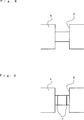
In
In
In
In
In
In
BeispieleExamples
In Tabelle 1 Defektprozent (Auftrittrate des Freilegens), Sichtbarkeit und Haltbarkeit in den Beispielen 1 bis 6 der
Hundert Testreifen mit dem Abnutzungsindikator 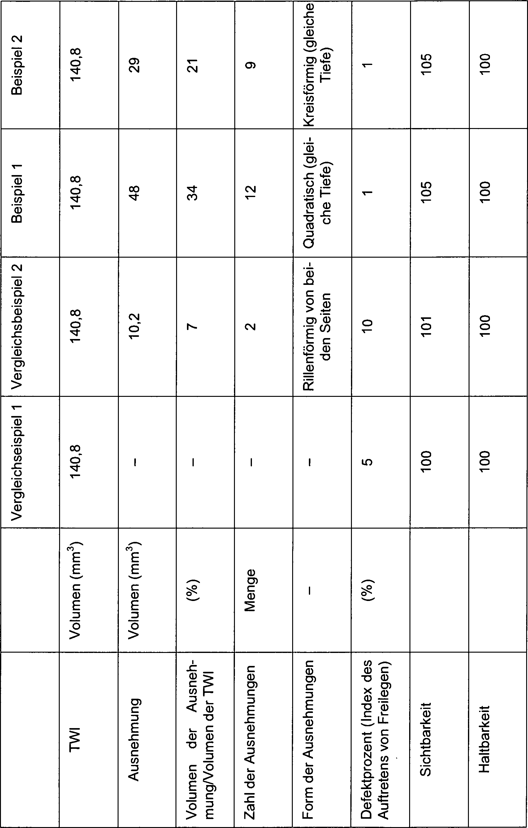
Wie anhand von Tabelle 1 erkannt werden kann, kann bei den Beispielen 1 bis 5 der Index des Auftretens von Freilegen signifikant verbessert werden und in Beispiel 6 besteht ein ausreichender Effekt. Zusätzlich kann in allen Beispielen 1 bis 6 die Sichtbarkeit verbessert werden. Zudem ist mit Ausnahme von Beispiel 5 die Haltbarkeit nicht verschlechtert. Anhand dieser Ergebnisse sind die Beispiele 1 und 2 besonders bevorzugt.As can be seen from Table 1, in Examples 1 to 5, the index of occurrence of exposure can be significantly improved, and in Example 6, there is a sufficient effect. In addition, visibility can be improved in all Examples 1 to 6. In addition, with the exception of Example 5, the durability is not deteriorated. Based on these results, Examples 1 and 2 are particularly preferred.
Die vorliegende Erfindung ist nicht auf die Konfigurationen beschränkt, die in der Ausführungsform beschrieben sind, und verschiedene Modifikationen können vorgenommen werden.The present invention is not limited to the configurations described in the embodiment, and various modifications can be made.
Bei der Ausführungsform wurde der Luftreifen mit der Unter-Rille
Auch ein Luftreifen mit lediglich der Hauptrille
In der Ausführungsform sind die Ausnehmungen
Bei dieser Ausführungsform, wie in
ZITATE ENTHALTEN IN DER BESCHREIBUNG QUOTES INCLUDE IN THE DESCRIPTION
Diese Liste der vom Anmelder aufgeführten Dokumente wurde automatisiert erzeugt und ist ausschließlich zur besseren Information des Lesers aufgenommen. Die Liste ist nicht Bestandteil der deutschen Patent- bzw. Gebrauchsmusteranmeldung. Das DPMA übernimmt keinerlei Haftung für etwaige Fehler oder Auslassungen.This list of the documents listed by the applicant has been generated automatically and is included solely for the better information of the reader. The list is not part of the German patent or utility model application. The DPMA assumes no liability for any errors or omissions.
Zitierte PatentliteraturCited patent literature
- JP 2010-234559 A [0002, 0005] JP 2010-234559 A [0002, 0005]
- JP 2002-22514 A [0003, 0006] JP 2002-22514 A [0003, 0006]
- JP 5-178021 A [0004, 0007] JP 5-178021 A [0004, 0007]
Claims (6)
Applications Claiming Priority (2)
| Application Number | Priority Date | Filing Date | Title |
|---|---|---|---|
| JP2012-047112 | 2012-03-02 | ||
| JP2012047112A JP6118029B2 (en) | 2012-03-02 | 2012-03-02 | Pneumatic tire |
Publications (2)
| Publication Number | Publication Date |
|---|---|
| DE102013203473A1 true DE102013203473A1 (en) | 2013-09-05 |
| DE102013203473B4 DE102013203473B4 (en) | 2017-05-24 |
Family
ID=48985230
Family Applications (1)
| Application Number | Title | Priority Date | Filing Date |
|---|---|---|---|
| DE102013203473.3A Active DE102013203473B4 (en) | 2012-03-02 | 2013-03-01 | tire |
Country Status (4)
| Country | Link |
|---|---|
| US (1) | US8985166B2 (en) |
| JP (1) | JP6118029B2 (en) |
| CN (1) | CN103287220B (en) |
| DE (1) | DE102013203473B4 (en) |
Families Citing this family (7)
| Publication number | Priority date | Publication date | Assignee | Title |
|---|---|---|---|---|
| FR3034359B1 (en) * | 2015-03-30 | 2018-03-23 | Compagnie Generale Des Etablissements Michelin | PNEUMATIC TIRE TREAD AND WEAR |
| USD823784S1 (en) * | 2017-01-24 | 2018-07-24 | The Goodyear Tire & Rubber Company | Tire tread wear indicator |
| US20180206594A1 (en) * | 2017-01-26 | 2018-07-26 | Tingley Rubber Corporation | Tread Wear Indicators For Outsoles Of Footwear |
| JP7017981B2 (en) * | 2018-05-18 | 2022-02-09 | Toyo Tire株式会社 | Pneumatic tires |
| DE102019213570A1 (en) * | 2019-09-06 | 2021-03-11 | Continental Reifen Deutschland Gmbh | Pneumatic vehicle tires |
| JP7384017B2 (en) * | 2019-12-13 | 2023-11-21 | 住友ゴム工業株式会社 | tire |
| US11413907B2 (en) | 2020-10-16 | 2022-08-16 | The Goodyear Tire & Rubber Company | Tire with shallow groove-based tread wear indicator |
Citations (3)
| Publication number | Priority date | Publication date | Assignee | Title |
|---|---|---|---|---|
| JPH05178021A (en) | 1991-12-26 | 1993-07-20 | Yokohama Rubber Co Ltd:The | Pneumatic tire |
| JP2002022514A (en) | 2000-07-10 | 2002-01-23 | Ricoh Co Ltd | Thermal flow sensor, flowmeter, method for detecting flow velocity, method for preparing table, and method for preparing relational expression |
| JP2010234559A (en) | 2009-03-30 | 2010-10-21 | Toyo Tire & Rubber Co Ltd | Tire vulcanizing die and pneumatic tire |
Family Cites Families (22)
| Publication number | Priority date | Publication date | Assignee | Title |
|---|---|---|---|---|
| US2706509A (en) * | 1950-04-01 | 1955-04-19 | Gates Rubber Co | Means for indicating tire tread wear |
| NL141130B (en) * | 1971-06-21 | 1974-02-15 | Vredestein Rubber | TIRE FOR LIGHT VEHICLES. |
| JPS61202902A (en) * | 1985-03-06 | 1986-09-08 | Bridgestone Corp | Pneumatic tire |
| EP0250113A3 (en) * | 1986-06-18 | 1988-09-28 | General Tire Inc. | Tire with tread wear indicating grooves |
| DE4410999A1 (en) * | 1994-03-30 | 1995-10-05 | Continental Ag | Vehicle tires with a stone deflector |
| JPH1044719A (en) * | 1996-08-05 | 1998-02-17 | Yokohama Rubber Co Ltd:The | Pneumatic studless tire |
| JPH11189016A (en) * | 1997-12-25 | 1999-07-13 | Bridgestone Corp | Pneumatic tire |
| FI112340B (en) * | 1999-06-29 | 2003-11-28 | Nokian Renkaat Oyj | Vehicle tire tread with means for indicating at any instant the depth of the tread grooves |
| JP4442039B2 (en) * | 2001-02-02 | 2010-03-31 | 横浜ゴム株式会社 | Pneumatic radial tire |
| US20060037683A1 (en) * | 2004-08-23 | 2006-02-23 | Andre Cuny | Tire tread wear indicator and molding device for forming a tread wear indicator |
| JP2006264480A (en) * | 2005-03-23 | 2006-10-05 | Yokohama Rubber Co Ltd:The | Pneumatic tire, and tire molding die |
| KR20070055872A (en) * | 2005-11-28 | 2007-05-31 | 한국타이어 주식회사 | Pneumatic vehicle tire |
| SK472006A3 (en) * | 2006-03-08 | 2007-10-04 | Matador A. S. | Tire for motor vehicle contains indicator of wear tire profile |
| US8695655B2 (en) * | 2007-10-15 | 2014-04-15 | The Goodyear Tire & Rubber Company | Tire tread with tread wear indicator |
| DE102008021497A1 (en) * | 2008-04-29 | 2009-11-05 | Continental Aktiengesellschaft | Pneumatic vehicle tire with a profile design with abrasion indicator |
| DE102008024075A1 (en) * | 2008-05-17 | 2009-11-19 | Continental Aktiengesellschaft | Vehicle tires |
| DE102009003592A1 (en) * | 2009-03-10 | 2010-09-16 | Continental Reifen Deutschland Gmbh | Vehicle tires |
| US20110079333A1 (en) * | 2009-10-06 | 2011-04-07 | Jacques Collette | Multi-level tire treadwear indicator |
| JP5567428B2 (en) * | 2010-08-05 | 2014-08-06 | 株式会社ブリヂストン | Pneumatic tire |
| FR2976520B1 (en) * | 2011-06-15 | 2014-05-09 | Michelin Soc Tech | PNEUMATIC COMPRISING MONOBARETTE SOUNDS OF WEAR |
| FR2976522B1 (en) * | 2011-06-15 | 2014-05-09 | Michelin Soc Tech | PNEUMATIC HAVING MULTINIVEAL WEAR WITNESSES |
| FR2976521B1 (en) * | 2011-06-15 | 2016-09-09 | Soc De Tech Michelin | METHOD OF UNIVERSALLY DETECTING THE WEAR THRESHOLD OF A TIRE |
-
2012
- 2012-03-02 JP JP2012047112A patent/JP6118029B2/en active Active
-
2013
- 2013-03-01 DE DE102013203473.3A patent/DE102013203473B4/en active Active
- 2013-03-01 CN CN201310065376.6A patent/CN103287220B/en active Active
- 2013-03-04 US US13/784,298 patent/US8985166B2/en not_active Expired - Fee Related
Patent Citations (3)
| Publication number | Priority date | Publication date | Assignee | Title |
|---|---|---|---|---|
| JPH05178021A (en) | 1991-12-26 | 1993-07-20 | Yokohama Rubber Co Ltd:The | Pneumatic tire |
| JP2002022514A (en) | 2000-07-10 | 2002-01-23 | Ricoh Co Ltd | Thermal flow sensor, flowmeter, method for detecting flow velocity, method for preparing table, and method for preparing relational expression |
| JP2010234559A (en) | 2009-03-30 | 2010-10-21 | Toyo Tire & Rubber Co Ltd | Tire vulcanizing die and pneumatic tire |
Also Published As
| Publication number | Publication date |
|---|---|
| JP6118029B2 (en) | 2017-04-19 |
| CN103287220A (en) | 2013-09-11 |
| CN103287220B (en) | 2015-12-09 |
| US20130228255A1 (en) | 2013-09-05 |
| US8985166B2 (en) | 2015-03-24 |
| DE102013203473B4 (en) | 2017-05-24 |
| JP2013180707A (en) | 2013-09-12 |
Similar Documents
| Publication | Publication Date | Title |
|---|---|---|
| DE102013203473B4 (en) | tire | |
| DE112017002741T5 (en) | tire | |
| DE102012011923B4 (en) | tire | |
| DE102011055916A1 (en) | Vehicle tires | |
| DE102011053416A1 (en) | Pneumatic tire and vulcanization mold for this | |
| DE102012201631A9 (en) | tire | |
| DE112014002818T5 (en) | tire | |
| DE102008015978A1 (en) | tire | |
| DE102015102614A1 (en) | tire | |
| DE102010061740A1 (en) | tire | |
| DE102015212995A1 (en) | Pneumatic tire | |
| DE102015106710A1 (en) | A heavy duty pneumatic tire | |
| DE102015215015A1 (en) | Pneumatic tire | |
| DE102013108786A1 (en) | vehicle tires | |
| DE102014005174A1 (en) | tire | |
| DE102015225419A1 (en) | vehicle tires | |
| DE102011009558A9 (en) | tire | |
| DE102019111987A1 (en) | Pneumatic tire | |
| DE112018004915T5 (en) | tire | |
| DE102005055857A1 (en) | tire | |
| DE102011005319A1 (en) | tire | |
| DE112019004945T5 (en) | tire | |
| DE102019211420A1 (en) | Mold segment and tire vulcanization mold | |
| DE102018221486A1 (en) | Pneumatic tire | |
| DE112018005915T5 (en) | tire |
Legal Events
| Date | Code | Title | Description |
|---|---|---|---|
| R012 | Request for examination validly filed | ||
| R016 | Response to examination communication | ||
| R018 | Grant decision by examination section/examining division | ||
| R020 | Patent grant now final |