DE102013100603B3 - Circuit arrangement for connecting electronic control unit to controller area network bus to test correct function of e.g. magnetic sensor of motor vehicle, has interface, where arrangement is bus-terminatingly configured at input or output - Google Patents
Circuit arrangement for connecting electronic control unit to controller area network bus to test correct function of e.g. magnetic sensor of motor vehicle, has interface, where arrangement is bus-terminatingly configured at input or output Download PDFInfo
- Publication number
- DE102013100603B3 DE102013100603B3 DE201310100603 DE102013100603A DE102013100603B3 DE 102013100603 B3 DE102013100603 B3 DE 102013100603B3 DE 201310100603 DE201310100603 DE 201310100603 DE 102013100603 A DE102013100603 A DE 102013100603A DE 102013100603 B3 DE102013100603 B3 DE 102013100603B3
- Authority
- DE
- Germany
- Prior art keywords
- bus
- input
- output
- circuit arrangement
- switch
- Prior art date
- Legal status (The legal status is an assumption and is not a legal conclusion. Google has not performed a legal analysis and makes no representation as to the accuracy of the status listed.)
- Active
Links
Images


Classifications
-
- G—PHYSICS
- G06—COMPUTING; CALCULATING OR COUNTING
- G06F—ELECTRIC DIGITAL DATA PROCESSING
- G06F13/00—Interconnection of, or transfer of information or other signals between, memories, input/output devices or central processing units
- G06F13/38—Information transfer, e.g. on bus
- G06F13/40—Bus structure
- G06F13/4004—Coupling between buses
- G06F13/4022—Coupling between buses using switching circuits, e.g. switching matrix, connection or expansion network
-
- H—ELECTRICITY
- H04—ELECTRIC COMMUNICATION TECHNIQUE
- H04L—TRANSMISSION OF DIGITAL INFORMATION, e.g. TELEGRAPHIC COMMUNICATION
- H04L12/00—Data switching networks
- H04L12/28—Data switching networks characterised by path configuration, e.g. LAN [Local Area Networks] or WAN [Wide Area Networks]
- H04L12/40—Bus networks
- H04L12/40006—Architecture of a communication node
- H04L12/40032—Details regarding a bus interface enhancer
-
- H—ELECTRICITY
- H04—ELECTRIC COMMUNICATION TECHNIQUE
- H04L—TRANSMISSION OF DIGITAL INFORMATION, e.g. TELEGRAPHIC COMMUNICATION
- H04L12/00—Data switching networks
- H04L12/28—Data switching networks characterised by path configuration, e.g. LAN [Local Area Networks] or WAN [Wide Area Networks]
- H04L12/40—Bus networks
- H04L12/40169—Flexible bus arrangements
-
- H—ELECTRICITY
- H04—ELECTRIC COMMUNICATION TECHNIQUE
- H04L—TRANSMISSION OF DIGITAL INFORMATION, e.g. TELEGRAPHIC COMMUNICATION
- H04L12/00—Data switching networks
- H04L12/28—Data switching networks characterised by path configuration, e.g. LAN [Local Area Networks] or WAN [Wide Area Networks]
- H04L12/42—Loop networks
Landscapes
- Engineering & Computer Science (AREA)
- Computer Networks & Wireless Communication (AREA)
- Signal Processing (AREA)
- Physics & Mathematics (AREA)
- General Engineering & Computer Science (AREA)
- Theoretical Computer Science (AREA)
- Mathematical Physics (AREA)
- Computer Hardware Design (AREA)
- General Physics & Mathematics (AREA)
- Bus Control (AREA)
- Small-Scale Networks (AREA)
- Logic Circuits (AREA)
Abstract
Description
Die Erfindung betrifft eine Schaltungsanordnung zum Anschließen eines Busteilnehmers an wenigstens einen Bus, insbesondere einen CAN Bus, mit einer Schnittstelle zur Verbindung des Busteilnehmers mit der Schaltungsanordnung, einem ersten Buseingang und einem ersten Busausgang, zwischen die der Busteilnehmer über die Schnittstelle schaltbar ist. Des Weiteren betrifft die Erfindung einen Busteilnehmer, insbesondere ein elektronisches Steuergerät für Kraftfahrzeuge, mit einer derartigen integrierten Schaltungsanordnung. Ferner betrifft die Erfindung ein System zur Funktionsüberprüfung von Busteilnehmern an einem Bus in einer Simulationsumgebung umfassend mehrere Schaltungsanordnungen und einen Bus, insbesondere einen CAN Bus, wobei die Busteilnehmer jeweils mittels einer der Schaltungsanordnungen mit dem Bus verbindbar sind, und ferner umfassend eine Simulatoreinheit zur Simulation von Steuersignalen auf dem Bus.The invention relates to a circuit arrangement for connecting a bus subscriber to at least one bus, in particular a CAN bus, with an interface for connecting the bus subscriber to the circuit arrangement, a first bus input and a first bus output, between which the bus subscriber can be switched via the interface. Furthermore, the invention relates to a bus subscriber, in particular an electronic control device for motor vehicles, with such an integrated circuit arrangement. The invention further relates to a system for functional testing of bus subscribers on a bus in a simulation environment comprising a plurality of circuit arrangements and a bus, in particular a CAN bus, wherein the bus subscribers can each be connected to the bus by means of one of the circuit arrangements, and further comprising a simulator unit for simulating Control signals on the bus.
Allgemein betrifft die Erfindung das technische Gebiet der Funktionsüberprüfung von einem oder mehreren elektronischen Steuergeräten mittels einer Simulationsumgebung, was allgemein als „Hardware in the Loop” (HIL) genannt wird. Dabei stellt das elektronische Steuergerät ein eingebettetes System dar, das mit seinen Ein- und Ausgängen an eine Simulatoreinheit angeschlossen ist, die die reale Umgebung des Systems, d. h. des bzw. der elektronischen Steuergeräte nachbildet. Die Funktionsüberprüfung umfasst insbesondere das Testen von Funktionen und des Fehlerverhaltens der Steuergeräte. Sie dient der Unterstützung während der Entwicklung der Hard- und Software der Geräte.Generally, the invention relates to the technical field of functional testing of one or more electronic control devices by means of a simulation environment, commonly referred to as "hardware in the loop" (HIL). In this case, the electronic control unit is an embedded system, which is connected with its inputs and outputs to a simulator unit, the real environment of the system, d. H. of the electronic control unit (s). The function check comprises, in particular, the testing of functions and the error behavior of the control devices. It serves the support during the development of the hardware and software of the devices.
Das HIL-Verfahren ist insbesondere im Automobilbereich weit verbreitet. Dabei wird das zu steuernde System, d. h. das Fahrzeug, über Modelle simuliert, um die korrekte Funktion des zu entwickelnden Steuergeräts, beispielsweise eines Motorsteuergeräts zu prüfen. Das Steuergerät kann eine beliebige elektronische, mechatronische oder magnetische Aktorik und/oder Sensorik sein, die beispielsweise zur Ansteuerung eines Elektromotors oder Betätigung eines Magnetventils dient. Die Simulation läuft in der Regel in Echtzeit. Die Eingänge einer Steuereinheit werden mit Sensordaten aus dem Modell beaufschlagt, und die in Reaktion auf die Eingangssignale am Ausgang der Steuereinheit erzeugten Ausgangssignale werden zurück in das Modell gegeben, so dass eine geschlossene Regelschleife vorliegt (Loop) vorliegt.The HIL process is particularly widespread in the automotive sector. In doing so, the system to be controlled, i. H. the vehicle, simulated by models to check the correct operation of the developing control device, such as an engine control unit. The control unit may be any electronic, mechatronic or magnetic actuators and / or sensors, which serves for example for controlling an electric motor or actuation of a solenoid valve. The simulation usually runs in real time. The inputs of a control unit are supplied with sensor data from the model, and the output signals generated in response to the input signals at the output of the control unit are fed back into the model so that a closed loop is present.
Für die Überprüfung der Funktionalität und Funktionsfähigkeit einzelner oder mehrerer Steuergeräte werden diese nach dem Stand der Technik an einen bestimmten Bus, z. B. einen Hauptbus (Mainbus) oder einen lokalen Bus (Localbus), durch eine entsprechende Verkabelung angeschlossen. Dies führt jedoch zu einem sehr unflexiblen Testaufbau. Eine Änderung der Busstruktur ist nur mit hohem Aufwand möglich, insbesondere muss eine Umschaltung vom Haupt- zum Lokalbus durch Änderung der Verkabelung erfolgen.For checking the functionality and functionality of individual or several control units, these are according to the prior art to a particular bus, z. B. a main bus (Mainbus) or a local bus (local bus), connected by an appropriate wiring. However, this leads to a very inflexible test setup. A change in the bus structure is possible only with great effort, in particular a changeover from the main to the local bus must be done by changing the wiring.
In der Vergangenheit wurden sogenannte Matrix-Boards verwendet, die Anschlüsse für mehrere Busse und mehrere Steuergeräte bereitstellen. Die Busleitungen und die Steuergeräteleitungen kreuzen sich in der Art einer Matrix, wobei an jedem Kreuzungspunkt eine Verbindung zwischen dem entsprechenden Bus und der entsprechenden Steuergeräteleitung herstellbar ist, so dass jedes Steuergerät wahlweise an einen der Busse anschließbar ist. Der Nachteil eines solchen Matrix-Boards liegt darin, dass nur eine begrenzte Anzahl an Steuergeräten bzw. Busteilnehmern anschließbar ist.In the past, so-called matrix boards have been used which provide connections for multiple buses and multiple controllers. The bus lines and the control unit lines intersect in the manner of a matrix, wherein at each crossing point, a connection between the corresponding bus and the corresponding control unit line can be produced, so that each control unit is selectively connectable to one of the buses. The disadvantage of such a matrix board is that only a limited number of control devices or bus subscribers can be connected.
Eine Schaltungsanordnung der einleitend genannten Art ist aus der
Aus der Druckschrift „Janssen, Dirk; Büttner, Holger: EtherCAT – Der Ethernet-Feldbus. In: Elektronik (2003), Nr. 23/2003, S. 64–72 und Nr. 25, S. 62–67” ist ein auf Ethernet basierender Feldbus bekannt, bei dem zur Erzielung einer Schleifentopologie die Rückleitung durch die einzelnen Teilnehmer durchgeschleift wird.From the publication "Janssen, Dirk; Büttner, Holger: EtherCAT - The Ethernet Fieldbus. In: Electronics (2003), no. 23/2003, pp. 64-72 and no. 25, pp. 62-67, "an Ethernet-based fieldbus is known, in which the return line is looped through the individual subscribers in order to achieve a loop topology becomes.
Aus der Druckschrift „Diekstall, K.; Schütte, H.; Wältermann, P.: Hardware-in-the-Loop-Test verteilter Kfz-Elektroniksysteme. In ATZ – Automobiltechnische Zeitschrift, 2004, Nr. 4, S. 416–425” ist ein Simulator zum Test von CAN-Bus basierten Kfz-Steuergeräten bekannt, wobei die CAN-Topologie über ein CAN-Matrix-Modul variabel umgeschaltet wird.From the publication "Diekstall, K .; Schütte, H .; Wältermann, P .: Hardware-in-the-loop test of distributed automotive electronics systems. ATZ - Automobiltechnische Zeitschrift, 2004, No. 4, pp. 416-425 "discloses a simulator for testing CAN bus-based vehicle control units, wherein the CAN topology is variably switched over via a CAN matrix module.
Es ist Aufgabe der vorliegenden Erfindung, eine Möglichkeit zu schaffen, eine hohe Flexibilität bei der Gestaltung der Busstruktur, insbesondere hinsichtlich der Wahl der Stelle der Terminierung des Busses, sowie eine hohe Flexibilität bei der Anzahl und der Verschaltung der Busteilnehmer mit einem bestimmten Bus zu erhalten, wobei der Arbeits- und Verkabelungsaufwand gleichzeitig gering sein soll und eine Änderung der Busstruktur sowie Umschaltung von einem auf einen anderen Bus während des HIL-Simulatorbetriebes ermöglicht werden soll.It is an object of the present invention to provide a possibility to obtain a high flexibility in the design of the bus structure, in particular with regard to the choice of the point of termination of the bus, as well as a high flexibility in the number and interconnection of bus subscribers with a particular bus , wherein the work and cabling effort should be low at the same time and a change in the bus structure and switching from one to another bus during the HIL simulator operation should be possible.
Diese Aufgabe wird durch eine Schaltungsanordnung nach Anspruch 1 sowie durch ein System nach Anspruch 17 gelöst. Vorteilhafte Weiterbildungen der Erfindung sind in den jeweiligen Unteransprüchen angegeben.This object is achieved by a circuit arrangement according to
Erfindungsgemäß wird eine Schaltungsanordnung zum Anschließen eines Busteilnehmers an wenigstens einen Bus, insbesondere einen CAN Bus, vorgeschlagen, mit einer Schnittstelle zur Verbindung des Busteilnehmers mit der Schaltungsanordnung, einem ersten Buseingang und einem ersten Busausgang, zwischen die der Busteilnehmer über die Schnittstelle schaltbar ist, wobei die Schaltungsanordnung einen zweiten Buseingang und einen zweiten Busausgang umfasst zum Anschluss des Busses an die Schaltungsanordnung in einer Ringtopologie derart, dass der erste Busausgang zumindest mittelbar über den Bus mit dem zweiten Buseingang und der zweite Busausgang zumindest mittelbar über den Bus mit dem ersten Buseingang verbunden ist, und wobei der Bus in der Schaltungsanordnung zum Erhalt einer Linientopologie auftrennbar ist, und die Schaltungsanordnung an einem der Buseingänge oder Busausgänge als busterminierend konfigurierbar ist.According to the invention, a circuit arrangement for connecting a bus subscriber to at least one bus, in particular a CAN bus, is proposed, with an interface for connecting the bus subscriber to the circuit arrangement, a first bus input and a first bus output, between which the bus subscriber can be switched via the interface, wherein the circuit arrangement comprises a second bus input and a second bus output for connecting the bus to the circuit arrangement in a ring topology such that the first bus output is at least indirectly connected via the bus to the second bus input and the second bus output at least indirectly via the bus to the first bus input and wherein the bus in the circuit arrangement is obtainable for obtaining a line topology, and the circuit arrangement at one of the bus inputs or bus outputs can be configured as bus terminating.
Eine derartige Schaltungsanordnung verbindet den Busteilnehmer mit dem Bus in der Art eines Gateway-Moduls. Ein Kernaspekt der Erfindung ist, dass der zweite Buseingang und Busausgang nicht für den Anschluss eines zweiten Busses sondern für denselben Bus vorgesehen sind, der schaltungstechnisch zunächst zu einer weiteren, identischen Schaltungsanordnung verläuft und dann von dieser wieder zurückkommt. Der Bus ist damit zweimal durch die Schaltungsanordnung durchgeleitet oder zumindest durchleitbar. Durch diese Verschaltbarkeit der Schaltungsanordnung nach Art einer Ringtopologie kann eine beliebige Anzahl von Busteilnehmern in eine HIL-Simulationsumgebung eingebettet und einzeln oder gemeinsam getestet werden.Such a circuit arrangement connects the bus subscriber with the bus in the manner of a gateway module. A key aspect of the invention is that the second bus input and the bus output are not provided for the connection of a second bus but for the same bus, the circuit initially runs to another identical circuit arrangement and then comes back from this. The bus is thus passed through the circuit twice or at least durchleitbar. As a result of this connectability of the circuit arrangement in the manner of a ring topology, an arbitrary number of bus users can be embedded in an HIL simulation environment and tested individually or together.
Ein weiterer Kernaspekt der Erfindung besteht darin, dass die erfindungsgemäße Schaltungsanordnung so konfiguriert werden kann, dass sie einen der Buseingänge oder Busausgänge terminiert. Dies ist dann von Vorteil, wenn der Busteilnehmer keine integrierte Terminierung aufweist und er oder die Schaltungsanordnung an einem Busende angeschlossen werden soll.Another key aspect of the invention is that the circuit arrangement according to the invention can be configured to terminate one of the bus inputs or bus outputs. This is advantageous if the bus subscriber has no integrated termination and he or the circuit is to be connected to a bus end.
Jede Schaltungsanordnung kann den an ihr angeschlossenen Busteilnehmer an den Bus anschließen oder von diesem trennen und die Busleitung sowohl zwischen dem ersten Buseingang und ersten Busausgang als auch zwischen dem zweiten Buseingang und zweiten Busausgang durchleiten oder auftrennen. Sie ermöglicht damit eine flexible Änderung der Busstruktur dahingehend, dass der Bus bei jeder Schaltungsanordnung aufgetrennt und an der dadurch entstehenden offenen Stelle als terminierend verschaltet werden kann.Each circuit arrangement can connect or disconnect the bus subscriber connected to it to the bus and divert or disconnect the bus line both between the first bus input and the first bus output and between the second bus input and the second bus output. It thus allows a flexible change of the bus structure to the effect that the bus can be separated in each circuit arrangement and connected as terminating at the resulting open position.
Bei einer Hardware-Simulationsumgebung mit mehreren Busteilnehmern unterschiedlicher Varianten können diese dann während der HIL-Simulation getestet werden. Jede Schaltungsanordnung kann einen Busteilnehmer mit dem Bus verbinden, den Bus alternativ durchschleifen und optional den Bus terminieren.In a hardware simulation environment with several bus participants of different variants, these can then be tested during the HIL simulation. Each circuitry may connect a bus subscriber to the bus, alternatively loop through the bus, and optionally terminate the bus.
Gemäß einer bevorzugten Ausführungsvariante kann die Schnittstelle über eine erste Schaltergruppe wahlweise mit dem ersten Buseingang und ersten Busausgang oder dem zweiten Buseingang und dem zweiten Busausgang verbunden werden, und die Verbindung von der ersten Schaltergruppe zum zweiten Buseingang und zum zweiten Busausgang jeweils durch eine Trennschaltergruppe aufgetrennt werden, um die Ringtopologie des Busses in eine Linientopologie zu ändern. Die Schaltungsanordnung besitzt in dieser Ausführungsvariante dann folglich eine erste Trennschaltergruppe, um die Verbindung zwischen dem zweiten Busausgang und der ersten Schaltergruppe aufzutrennen, sowie eine zweite Trennschaltergruppe, um die Verbindung zwischen dem zweiten Buseingang und der ersten Schaltergruppe aufzutrennen.According to a preferred embodiment variant, the interface can be selectively connected to the first bus input and the first bus output or the second bus input and the second bus output via a first switch group, and the connection from the first switch group to the second bus input and to the second bus output can each be separated by a disconnect switch group to change the ring topology of the bus into a line topology. In this embodiment, the circuit arrangement consequently has a first disconnect switch group in order to separate the connection between the second bus output and the first switch group, and a second disconnect switch group in order to separate the connection between the second bus input and the first switch group.
Die beiden Trennschaltergruppen sind vorzugsweise unabhängig voneinander schaltbar. Ist die zweite Trennschaltergruppe geschlossen, besteht eine Verbindung zwischen dem zweiten Buseingang zur ersten Schaltergruppe. Ist die erste Trennschaltergruppe geschlossen, besteht eine Verbindung zwischen dem zweiten Busausgang zur ersten Schaltergruppe. Sind beide Trennschaltergruppen geschlossen, liegt folglich eine Verbindung zwischen dem zweiten Buseingang und dem zweiten Busausgang vor. Wird eine der Trennschaltergruppen betätigt, d. h. die Verbindung geöffnet, während die andere Trennschaltergruppe geschlossen verleibt, liegt ein offenes Ende des Busses an der ersten Schaltergruppe vor, sofern der Busteilnehmer nicht über die erste Schaltergruppe mit diesem Ende verbunden wird bzw. verbunden ist.The two circuit breaker groups are preferably independently switchable. If the second disconnect switch group is closed, there is a connection between the second bus input to the first switch group. If the first disconnect switch group is closed, there is a connection between the second bus output to the first switch group. If both circuit breaker groups are closed, there is consequently a connection between the second bus input and the second bus output. If one of the breaker groups is actuated, i. H. the connection is opened while the other circuit breaker group is closed, an open end of the bus is present at the first switch group unless the bus subscriber is connected to that end via the first switch group.
Dieses durch die Auftrennung entstehende offene Ende des Busses ist elektrisch abzuschließen, um Reflexionen zu vermeiden und um die Buskommunikation nicht zu beeinflussen. Hierzu kann die Schaltungsanordnung eine Terminierungseinheit des Busses, insbesondere einen Abschlusswiderstand, aufweisen, die über zumindest einen Terminierungsschalter in Abhängigkeit der Stellung der Schalter der Trennschaltergruppe an den zweiten Buseingang und/oder den zweiten Busausgang anschaltbar ist. Der Terminierungsschalter schaltet die Terminierungseinheit zu oder ab. Wird die zweite Trennschaltergruppe geöffnet und die Terminierungseinheit zugeschaltet, wird nachfolgend von einer linksseitigen Terminierung gesprochen. Wird die erste Trennschaltergruppe geöffnet und die Terminierungseinheit zugeschaltet, wird entsprechend nachfolgend von einer rechtsseitigen Terminierung gesprochen.This open end of the bus resulting from the separation must be electrically terminated in order to avoid reflections and not to influence the bus communication. For this purpose, the circuit arrangement can have a termination unit of the bus, in particular a terminating resistor, which can be connected to the second bus input and / or the second bus output via at least one termination switch as a function of the position of the switches of the disconnect switch group. The termination switch switches the termination unit on or off. If the second disconnect switch group is opened and the termination unit is switched on, the following is spoken of a left-side termination. If the first circuit breaker group is opened and the Scheduling unit switched on, is spoken accordingly below from a right-sided termination.
Es sei angemerkt, dass der an den Bus anzuschließende Busteilnehmer grundsätzlich auch selbst bereits eine Terminierungseinheit aufweisen kann. Die Terminierung in der erfindungsgemäßen Schaltungseinheit bietet jedoch eine hohe Flexibilität hinsichtlich der Anschlussmöglichkeiten des Busteilnehmers, ohne dabei eine Verkabelungsänderung vorzunehmen. So kann die Terminierungseinheit der Schaltungsanordnung sowohl zum terminieren des Busses, wenn der terminierende Busteilnehmer abgeklemmt ist, als auch für Busteilnehmer eingesetzt werden, die keine integrierte Terminierung besitzen. Dies kann beispielsweise bei Busteilnehmern der Fall sein, die sich noch in einer frühen Entwicklungsphase befinden, oder bei Busteilnehmern der Fall sein, die eigentlich für eine Anordnung mittig im Bus vorgesehen sind, aber zu Testzwecken an einen weiteren Bus als Endgerät angeschlossen werden sollen. Auch bietet die schaltungsintegrierte Terminierungseinheit den Vorteil, dass die Position eines Busteilnehmers am Bus geändert werden kann, ohne dass es hierzu einer Umverkabelung des Busteilnehmers oder eines manuellen Herstellens einer Terminierung bedarf. Eine solche Positionsänderung ist vor allem für Busteilnehmer aus unterschiedlichen Entwicklungsstufen interessant. Dies bietet große Vorteile, da zum Zeitpunkt der Verkabelung nicht klar sein muss welcher Busteilnehmer terminiert.It should be noted that the bus subscriber to be connected to the bus can in principle also already have a termination unit itself. The termination in the circuit unit according to the invention, however, offers a high degree of flexibility with regard to the connection options of the bus user, without making a cabling change. Thus, the termination unit of the circuit arrangement can be used both for terminating the bus when the terminating bus subscriber is disconnected and for bus users who have no integrated termination. This may be the case, for example, with bus subscribers who are still in an early development phase, or with bus subscribers who are actually intended for an arrangement in the middle of the bus, but are to be connected to a further bus as a terminal for test purposes. The circuit-integrated termination unit also offers the advantage that the position of a bus subscriber on the bus can be changed without the need for a rewiring of the bus subscriber or the manual establishment of a termination. Such a change in position is especially interesting for bus subscribers from different development stages. This offers great advantages, since at the time of cabling, it does not have to be clear which bus subscriber is terminating.
Grundsätzlich entsteht durch das Öffnen einer Trennschaltergruppe auch ein offenes Ende des Busses an der auftrennenden Trennschaltergruppe. Dieses muss jedoch nicht terminieren, wenn der dort ankommende Bus bereits durch eine andere Schaltungsanordnung „tot” gelegt wurde, d. h. eine Auftrennung an der komplementären Trennschaltergruppe einer anderen Schaltungsanordnung erfolgt ist, die gemäß der Ringtopologie vor der erstgenannten Schaltungsanordnung am Bus angeschlossenen ist. Damit ist die Gesamtbusstruktur dann derart, dass eine Schaltungsanordnung am Bus als rechtsterminierend und eine andere Schaltungsanordnung am Bus als linksterminierend zu konfigurieren ist. Der Busleitungsabschnitt, der zwischen einer linksterminierenden Schaltungsanordnung und einer rechtsterminierenden Schaltungsanordnung liegt, kann auf diese Weise folglich „tot” gelegt werden.In principle, the opening of a disconnect switch group also creates an open end of the bus at the disconnecting disconnect group. However, this does not have to terminate if the bus arriving there has already been "dead" by means of another circuit arrangement, ie. H. a separation of the complementary circuit breaker group of another circuit arrangement is carried out, which is connected according to the ring topology before the former circuit arrangement on the bus. Thus, the overall bus structure is then such that one circuit arrangement on the bus is to be configured as legally terminating and another circuit arrangement on the bus as left terminating. The bus line section which lies between a left-terminating circuit arrangement and a right-terminating circuit arrangement can thus be "dead" in this way.
Die Begriffe „Schaltergruppe” und „Trennschaltergruppe” umfassen hier sowie nachfolgend eine Gruppe von zwei oder mehr Schaltern, die dieselbe Funktion erfüllen und daher gleichzeitig geschaltet werden. Die Begriffe berücksichtigen die Tatsache, dass bei der Buskommunikation innerhalb der Schaltungseinheit bezüglich der Richtung (in/out) zu differenzieren ist, und dass bei mehradrigen Bussystemen, insbesondere bei Bussystemen, die Differenzsignale mit komplementären Signalpegeln in den Leitungen verwenden, wie dies beim CAN Bus (Controller Area Network) nach ISO 11898 der Fall ist, entsprechende Schalter für jeden Signalpfad vorzusehen sind.The terms "switch group" and "switch group" here and below include a group of two or more switches that perform the same function and are therefore switched simultaneously. The terms take into account the fact that in bus communication within the circuit unit, differentiation is to be made with respect to direction (in / out), and that in multicore bus systems, especially in bus systems, use the differential signals with complementary signal levels in the lines, as in the CAN bus (Controller Area Network) according to ISO 11898 is the case, appropriate switches are provided for each signal path.
Vorteilhafterweise kann die Terminierungseinheit an einem Knoten zwischen der Schnittstelle und der ersten Schaltergruppe angeordnet sein. Damit wird erreicht, dass sie in Abhängigkeit der Stellung der ersten Schaltergruppe an den ersten Buseingang oder den zweiten Buseingang und zweiten Busausgang anschaltbar ist. Damit kann also alternativ auch der erste Buseingang in der Schaltungsanordnung als terminierend konfiguriert werden.Advantageously, the termination unit can be arranged at a node between the interface and the first switch group. This ensures that it can be connected in dependence on the position of the first switch group to the first bus input or the second bus input and second bus output. Thus, alternatively, the first bus input in the circuit arrangement can also be configured as terminating.
Vorzugsweise weisen die Trennschaltergruppen jeweils Wechselschalter auf, wobei die den zweiten Buseingang und/oder den zweiten Busausgang wahlweise zur ersten Schaltergruppe hin oder zu einer Bypassleitung hin verbinden. Über die Bypassleitung können der zweite Buseingang und der zweite Busausgang ebenfalls direkt miteinander verbunden werden. Damit wird erreicht, dass die zur ersten Schaltergruppe führende Leitung mittels der Bypassleitung überbrückt wird, wenn beide Trennschaltergruppen auf die Bypassleitung geschaltet sind. Besagte Leitung würde kommunikationstechnisch eine „Sackgasse” bedeuten, an deren Ende Reflexionen entstehen können. Durch die Umschaltung der Verbindung zwischen zweitem Buseingang und zweitem Busausgang auf die Bypassleitung wird die Entstehung von Reflexionen am offenen Ende besagter Leitung verhindert.Preferably, the circuit breaker groups each have changeover switches, which connect the second bus input and / or the second bus output either to the first switch group or to a bypass line out. Via the bypass line, the second bus input and the second bus output can also be directly connected to each other. This ensures that the leading to the first switch group line is bridged by means of the bypass line when both disconnector groups are connected to the bypass line. In terms of communication technology, said management would mean a "dead end" that could lead to reflections. By switching the connection between the second bus input and the second bus output to the bypass line, the generation of reflections at the open end of said line is prevented.
Es sei angemerkt, dass bei einer mehradrigen Verdrahtung des Busses, entsprechend so viele Bypassleitungen wie Adern vorgesehen sein können.It should be noted that with multi-core wiring of the bus, as many bypass lines as cores may be provided.
Gemäß einer vorteilhaften Weiterbildung kann die Schaltungsanordnung eine Überbrückungsschaltergruppe zur direkten Verbindung des ersten Buseingangs mit dem ersten Busausgang aufweisen. Als direkte Verbindung ist in diesem Sinne zu verstehen, dass der Bus vom ersten Buseingang zum ersten Busausgang durchgeleitet und nicht über den Busteilnehmer durchgeschleift ist. Die Überbrückungsschaltergruppe überbrückt demgemäß die erste Schaltergruppe. Dies hat den Vorteil, dass der Busteilnehmer im laufenden Betrieb vom Bus abgeklemmt werden kann, ohne dass die Buskommunikation unterbrochen wird.According to an advantageous development, the circuit arrangement can have a bypass switch group for direct connection of the first bus input to the first bus output. As a direct connection is to be understood in this sense that the bus is passed from the first bus input to the first bus output and not looped through the bus station. The bypass switch group accordingly bypasses the first switch group. This has the advantage that the bus subscriber can be disconnected from the bus during operation without the bus communication being interrupted.
Auch die Überbrückungsschaltergruppe kann aus mehreren Schaltern bestehen, sofern der Bus mehradrig ausgeführt ist, wobei dann für jede Ader, d. h. für jeden Signalweg ein Überbrückungsschalter vorgesehen sein kann. Die Überbrückungsschalter müssen hier jedoch nicht gleichzeitig schaltbar sein. Vielmehr ist es für einzelne Verschaltungsvarianten von Vorteil, die Überbrückungsschalter einer Überbrückungsschaltergruppe getrennt voneinander schaltbar zu haben.The bridging switch group may consist of several switches, provided that the bus is designed multi-core, in which case a bypass switch can then be provided for each wire, ie for each signal path. However, the bypass switches need not be switchable at the same time here. Rather, it is for individual Verschaltungsvarianten advantageous to have the bypass switch of a bypass switch group separated from each other.
Zusätzlich oder alternativ zu den vorgenannten Merkmalen kann die Schaltungsanordnung eine Aktivierungsschaltergruppe aufweisen, über die die Schnittstelle mit der ersten Schaltergruppe verbindbar ist. Die Aktivierungsschaltergruppe dient zur Ankopplung und Abkopplung des Busteilnehmers an den bzw. von dem Bus. Der Busteilnehmer kann damit eingeschaltet (enable) und ausgeschaltet (disable) werden.In addition or as an alternative to the aforementioned features, the circuit arrangement can have an activation switch group, via which the interface can be connected to the first switch group. The activation switch group is used for coupling and decoupling of the bus device to and from the bus. The bus user can be switched on (enable) and switched off (disabled).
Auch die Aktivierungsschaltergruppe kann aus mehreren Schaltern bestehen. So kann insbesondere ein Aktivierungsschalter für den Signaleingang, d. h. vom ersten Buseingang kommenden Signalweg, und ein Aktivierungsschalter für den Signalausgang, d. h. zum ersten Busausgang gehenden Signalweg vorgesehen sein, die gemeinsam ein Schalterpaar bilden.The activation switch group may consist of several switches. Thus, in particular, an activation switch for the signal input, d. H. signal path from the first bus input, and an activation switch for the signal output, i. H. be provided for the first bus output going signal path, which together form a pair of switches.
Sofern der Bus mehradrig ausgeführt ist, kann die Aktivierungsschaltergruppe jeweils ein Schalterpaar für jede Leitung des Busses aufweisen. Diese Ausführungsvariante ist insbesondere für zweiadrige CAN Busse geeignet, die differentielle Bussignale verwenden und eine Busleitung für High (H) und eine Busleitung für Low (L) verwenden. Vorzugsweise sind die Schalterpaare getrennt voneinander schaltbar. Dies hat den Vorteil, dass die Transceiver-Modi der Busteilnehmer einzeln getestet werden können, sowie die Notfallmodi überprüfbar sind, falls eine Leitung eine Unterbrechung oder einen Kurzschluss aufweist.If the bus is multi-core, the activation switch group can each have a switch pair for each line of the bus. This embodiment variant is particularly suitable for two-wire CAN buses that use differential bus signals and use a bus line for high (H) and a bus line for low (L). Preferably, the switch pairs are switchable separately. This has the advantage that the transceiver modes of the bus subscribers can be tested individually, as well as the emergency modes are verifiable, if a line has an interruption or a short circuit.
Jedes Schalterpaar der Aktivierungsschaltergruppe kann wiederum einen Schalter für den kommenden Signalweg (in) und den abgehenden Signalweg (out) in Bezug auf den Busteilnehmer aufweisen. In Summe umfasst die Aktivierungsschaltergruppe dann vier Schalter. Die Schalter eines jeweiligen Aktivierungsschalterpaars können gemeinsam angesteuert sein und entsprechend gleichzeitig schalten.Each switch pair of the activation switch group may in turn comprise a switch for the incoming signal path (in) and the outgoing signal path (out) with respect to the bus subscriber. In total, the activation switch group then includes four switches. The switches of a respective activation switch pair can be driven together and switch simultaneously.
Vorzugsweise umfasst die erste Schaltergruppe mehrere Wechselschalter. Mittels der Wechselschalter kann wahlweise zwischen einer Verbindung der Schnittstelle respektive des Busteilnehmers zum ersten Busein- und Busausgang und einer Verbindung zum zweiten Busein- und Busausgang hergestellt werden. Insbesondere kann je ein Wechselschalter für den vom ersten Buseingang kommenden Signalweg (in) und für den zum ersten Busausgang abgehenden Signalweg (out) vorgesehen sein. Auch hier können diese Wechselschalter ein Schalterpaar bilden, die gemeinsam angesteuert werden.Preferably, the first switch group comprises a plurality of changeover switches. By means of the changeover switch can be made either between a connection of the interface or the bus device to the first Busein- and bus output and a connection to the second Busein- and bus output. In particular, a changeover switch can each be provided for the signal path (in) coming from the first bus input and for the signal path (out) going out to the first bus output. Again, these changeover switch can form a switch pair, which are controlled together.
Sofern der Bus mehradrig ausgeführt ist, kann für jede Busleitung H, L ein solches Schalterpaar für den kommenden und den abgehenden Signalweg (in, out) vorhanden sein. Vorzugsweise können alle Schalterpaare der ersten Schaltergruppe gleichzeitig miteinander schaltbar sein. Dies hat den Vorteil, dass letztendlich nur eine einzige Treiberschaltung für die Betätigung aller Schalter der ersten Schaltergruppe erforderlich ist.If the bus is designed multi-core, for each bus line H, L, such a pair of switches for the incoming and the outgoing signal path (in, out) may be present. Preferably, all pairs of switches of the first switch group can be simultaneously switched together. This has the advantage that ultimately only a single driver circuit for the actuation of all switches of the first group of switches is required.
Grundsätzlich hat die Zusammenlegung zu gemeinsam geschalteten Schalterpaaren oder Schaltergruppen bei allen Schaltern den Vorteil der Reduzierung des Ansteuerungsaufwandes aufgrund weniger Steuersignale sowie der Verringerung der Anzahl der Treiberschaltungen, so dass hierdurch sowohl eine Platzeinsparung in baulicher Hinsicht als auch eine Kosteneinsparung durch weniger erforderliche Komponenten erreicht wird.Basically, the combination of commonly switched switch pairs or switch groups in all switches has the advantage of reducing the driving effort due to fewer control signals and reducing the number of driver circuits, so that both a space saving in terms of construction and cost savings is achieved by less required components.
Gemäß einer besonders bevorzugten Weiterbildung kann die Schaltungsanordnung weitere Anschlüsse zum Anschluss an einen zweiten Bus, insbesondere einen zweiten CAN Bus, aufweisen, und eine Busumschaltergruppe umfassen, mittels welcher die Schnittstelle wahlweise an den ersten Bus oder an den zweiten Bus anschließbar ist. Durch die Busumschaltergruppe kann somit festgelegt werden, ob der Busteilnehmer am ersten Bus oder am zweiten Bus kommuniziert.According to a particularly preferred development, the circuit arrangement can have further connections for connection to a second bus, in particular a second CAN bus, and comprise a bus changeover group, by means of which the interface can be optionally connected to the first bus or to the second bus. The bus switch group can thus be used to determine whether the bus user is communicating on the first bus or on the second bus.
Vorteilhaft ist es, wenn die Busumschaltergruppe schaltungstechnisch zwischen der Schnittstelle und der ersten Schaltergruppe angeordnet ist. Dadurch reduziert die Anzahl der für die Busumschaltergruppe benötigten Schalter und vereinfacht sich das Schaltungslayout der Schaltungsanordnung.It is advantageous if the Busumschaltergruppe is arranged circuitry between the interface and the first switch group. This reduces the number of switches needed for the bus switch group and simplifies the circuit layout of the circuitry.
Vorzugsweise ist die Busumschaltergruppe durch Wechselschalter gebildet, mittels denen zwischen dem ersten Bus und dem zweiten Bus hin und her geschaltet werden kann. Dabei kann die Busumschaltergruppe mehrere Wechselschalter umfassen. Mittels dieser Wechselschalter kann wahlweise eine Verbindung der Schnittstelle respektive des Busteilnehmers zu dem ersten Bus oder zu dem zweiten Bus hergestellt werden. Dies bedeutet, dass entweder eine Verbindung der Schnittstelle mit dem ersten Buseingang und Busausgang des ersten Busses oder, in Abhängigkeit der Stellung des ersten Schalterpaares, mit dem zweiten Buseingang und Busausgang des ersten Busses herstellbar ist, oder dass eine Verbindung der Schnittstelle mit dem ersten Buseingang und Busausgang des zweiten Busses oder, in Abhängigkeit der Stellung eines zweiten Schalterpaares, mit dem zweiten Buseingang und Busausgang des zweiten Busses herstellbar ist.Preferably, the Busumschaltergruppe is formed by changeover switches, by means of which between the first bus and the second bus can be switched back and forth. The Busumschaltergruppe may include several changeover switch. By means of this changeover switch can be made either a connection of the interface or the bus user to the first bus or to the second bus. This means that either a connection of the interface with the first bus input and bus output of the first bus or, depending on the position of the first switch pair, with the second bus input and bus output of the first bus can be produced, or that a connection of the interface with the first bus input and bus output of the second bus or, depending on the position of a second switch pair, with the second bus input and bus output of the second bus can be produced.
Insbesondere kann je ein Wechselschalter für den zur Schnittstelle hingehenden Signalweg (in) und für den von der Schnittstelle kommenden Signalweg (out) vorgesehen sein. Auch hier können diese Wechselschalter zu einem Schalterpaar zusammengefasst sein, wobei die Wechselschalter gemeinsam ansteuerbar sind.In particular, depending on a changeover switch for the signal going to the interface (in) and be provided for coming from the interface signal path (out). Again, these changeover switch can be combined to form a switch pair, the changeover switch can be controlled together.
Sofern die beiden Busse mehradrig ausgeführt sind, kann für jede Busleitung (H, L) ein solches Schalterpaar für den von der Schnittstelle kommenden und den zu ihr gehenden Signalweg vorhanden sein. Vorzugsweise können alle Schalterpaare der ersten Schaltergruppe gleichzeitig miteinander schaltbar sein. Dies hat auch hier den Vorteil, dass nur eine einzige Treiberschaltung für die Betätigung aller Schalter der Busumschaltergruppe erforderlich ist.If the two buses are designed multi-core, for each bus line (H, L), such a pair of switches for the coming and coming from the interface signal path can be present. Preferably, all pairs of switches of the first switch group can be simultaneously switched together. This also has the advantage that only a single driver circuit for the actuation of all switches of Busumschaltergruppe is required.
Die Schaltungsanordnung kann – wie zuvor bereits angesprochen – für den zweiten Bus ebenfalls einen ersten Buseingang, einen ersten Busausgang, einen zweiten Buseingang und einen zweiten Busausgang derart aufweisen, dass auch der zweite Bus in einer Ringtopologie derart verlegbar ist, dass der erste Busausgang zumindest mittelbar über den zweiten Bus mit dem zweiten Buseingang und der zweite Busausgang zumindest mittelbar über den zweiten Bus mit dem ersten Buseingang verbunden ist. Auch für den zweiten Bus wird dadurch ein Höchstmaß an Flexibilität hinsichtlich der Busstruktur des zweiten Busses, der Anschaltung des Busteilnehmers sowie auch hinsichtlich der Art der Anschaltung als busterminierend oder nicht busterminierend erreicht.As already mentioned above, the circuit arrangement can likewise have a first bus input, a first bus output, a second bus input and a second bus output in such a way that the second bus can also be laid in a ring topology such that the first bus output is at least indirectly is connected via the second bus to the second bus input and the second bus output at least indirectly via the second bus to the first bus input. For the second bus as a maximum of flexibility in terms of the bus structure of the second bus, the connection of the bus station and also with respect to the type of connection as busterminierend or busterminierend achieved.
Wie ebenfalls bereits angesprochen, kann die Schaltungsanordnung in der Ausführungsvariante mit einer Anschlussmöglichkeit zu einem zweiten Bus eine zweite Schaltergruppe umfassen, mittels welcher die Schnittstelle in der den zweiten Bus auswählenden Stellung der Busumschaltergruppe wahlweise mit dem ersten Buseingang und ersten Busausgang des zweiten Busses oder dem zweiten Buseingang und zweiten Busausgang des zweiten Busses verbindbar ist. Die zweite Schaltergruppe kann aufgrund ihres gleichen Zwecks und gleicher Funktionalität wie die erste Schaltergruppe identisch zu dieser aufgebaut sein.As also already mentioned, the circuit arrangement in the embodiment variant with a connection possibility to a second bus can comprise a second switch group, by means of which the interface in the second bus selecting position of Busumschaltergruppe optionally with the first bus input and first bus output of the second bus or the second Bus input and second bus output of the second bus can be connected. The second switch group can be constructed identical to this because of their same purpose and the same functionality as the first switch group.
Wie bei der internen Verschaltung der vom ersten Bus kommenden (in) bzw. zum ersten Bus gehenden Signalwege (out) kann auch die Verbindung von der zweiten Schaltergruppe zum zweiten Buseingang und zum zweiten Busausgang des zweiten Busses jeweils durch eine Trennschaltergruppe auftrennbar ausgeführt sein, um die Ringtopologie des zweiten Busses in eine Linientopologie zu ändern. Diese Trennschaltergruppe kann identisch zu der zuvor beschriebenen Trennschaltergruppe ausgebildet sein.As with the internal interconnection of coming from the first bus (in) or the first bus going signal paths (out) and the connection from the second switch group to the second bus input and the second bus output of the second bus can be separable by a disconnect switch group to run change the ring topology of the second bus into a line topology. This circuit breaker group may be identical to the circuit breaker group described above.
Insbesondere können die beiden Trennschaltergruppen für den zweiten Bus jeweils Wechselschalter umfassen, die den zweiten Buseingang und/oder den zweiten Busausgang des zweiten Busses wahlweise zur zweiten Schaltergruppe hin oder zu einer weiteren Bypassleitung hin verbinden. Über die weitere Bypassleitung kann wie bei der anderen Bypassleitung eine direkte Verbindung zwischen dem zweiten Buseingang und dem zweiten Busausgang des zweiten Busses geschaffen werden, wodurch die Leitung von den Trennschaltergruppen zur zweiten Schaltergruppe überbrückt wird. Auch dies dient der Verhinderung von Reflexionen, die auftreten könnten, wenn der zweite Buseingang und der zweite Busausgang des zweiten Busses über diese Leitung zur zweiten Schaltergruppe miteinander verbunden wären.In particular, the two circuit breaker groups for the second bus can each comprise changeover switches which selectively connect the second bus input and / or the second bus output of the second bus to the second switch group or to a further bypass line. As in the case of the other bypass line, a direct connection between the second bus input and the second bus output of the second bus can be created via the further bypass line, as a result of which the line is bridged by the disconnect switch groups to the second switch group. This also serves to prevent reflections that could occur if the second bus input and the second bus output of the second bus were connected to one another via this line to the second switch group.
Sofern der zweite Bus mehradrig, insbesondere zweiadrig ausgeführt ist, umfassen die Trennschaltergruppen jeweils einen Wechselschalter für jede Busleitung (H, L). Vorzugsweise sind die Wechselschalter einer Trennschaltergruppe gleichzeitig angesteuert, um die Anzahl der Schalteransteuerungen gering zu halten.If the second bus is multicore, in particular two-wire, the disconnect switch groups each comprise a changeover switch for each bus line (H, L). Preferably, the changeover switches of a circuit breaker group are simultaneously activated in order to keep the number of switch actuators low.
Die erfindungsgemäße Schaltungsanordnung kann eine zweite Terminierungseinheit zum elektrischen Abschluss des zweiten Busses aufweisen, die über zumindest einen Terminierungsschalter in Abhängigkeit der Stellung der genannten Trennschaltergruppen an den zweiten Buseingang oder den zweiten Busausgang anschaltbar ist. Hierzu kann die zweite Terminierungseinheit an einem Knoten zwischen der Schnittstelle und der zweiten Schaltergruppe derart angeordnet sein, dass sie in Abhängigkeit der Stellung der zweiten Schaltergruppe entweder an den ersten Buseingang oder den zweiten Buseingang bzw. zweiten Busausgang des zweiten Busses anschaltbar ist. Hierdurch wird auch für den zweiten Bus ein Höchstmaß an Flexibilität bei der Beschaltung der Schaltungsanordnung mit dem zweiten Bus und für die entsprechende Gestaltung der Busstruktur erreicht.The circuit arrangement according to the invention can have a second termination unit for the electrical termination of the second bus, which can be connected to the second bus input or the second bus output via at least one termination switch as a function of the position of said disconnect switch groups. For this purpose, the second termination unit can be arranged at a node between the interface and the second switch group such that it can be connected to either the first bus input or the second bus input or second bus output of the second bus depending on the position of the second switch group. As a result, a maximum of flexibility in the wiring of the circuit arrangement with the second bus and for the corresponding design of the bus structure is achieved for the second bus.
Sofern der zweite Bus mehradrig, insbesondere zweiadrig aufgebaut ist, kann auch die zweite Schaltergruppe jeweils einen Wechselschalter für jede der Adern umfassen. Dies bedeutet beispielsweise für einen CAN Bus mit differenziellen Signalen H und L, d. h. für einen Bus mit zwei Adern, dass die zweite Schaltergruppe vier Wechselschalter aufweist, nämlich ein Wechselschalterpaar für jede Ader, wobei ein Wechselschalterpaar jeweils einen Wechselschalter für den Signaleingang und für den Signalausgang aufweist. Dies kann natürlich auch für den ersten Bus realisiert werden.If the second bus is multi-core, in particular two-wire, the second switch group can also comprise a changeover switch for each of the wires. This means, for example, for a CAN bus with differential signals H and L, d. H. for a bus with two wires, that the second switch group has four changeover switches, namely a pair of changeover switches for each wire, wherein a pair of changeover switches each have a changeover switch for the signal input and for the signal output. This can of course also be realized for the first bus.
Gemäß einer vorteilhaften Weiterbildung kann die Schaltungsanordnung auch für den zweiten Bus eine Überbrückungsschaltergruppe zur direkten Verbindung des ersten Buseingangs mit dem ersten Busausgang des zweiten Busses aufweisen. Dies ermöglicht, dass auch der zweite Bus vom ersten Buseingang zum ersten Busausgang durchgeleitet und nicht über den Busteilnehmer durchgeschleift werden muss. Diese zweite Überbrückungsschaltergruppe überbrückt demgemäß die zweite Schaltergruppe und bietet damit den Vorteil, dass der Busteilnehmer im laufenden Betrieb vom zweiten Bus abgeklemmt werden kann, ohne dass die Buskommunikation auf dem zweiten Bus unterbrochen wird.According to an advantageous development, the circuit arrangement for the second Bus have a bypass switch group for direct connection of the first bus input to the first bus output of the second bus. This makes it possible for the second bus to also be routed from the first bus input to the first bus output and not looped through the bus subscriber. This second bypass switch group accordingly bridges the second switch group and thus offers the advantage that the bus subscriber can be disconnected during operation from the second bus without interrupting the bus communication on the second bus.
Auch die zweite Überbrückungsschaltergruppe kann aus mehreren Schaltern bestehen, sofern der zweite Bus mehradrig ausgeführt ist, wobei dann für jede Ader, d. h. für jeden Signalweg ein Überbrückungsschalter vorgesehen sein kann. Die Überbrückungsschalter müssen hier ebenfalls nicht unbedingt gleichzeitig schaltbar sein. Vielmehr ist es für einzelne Verschaltungsvarianten der Schaltungsanordnung von Vorteil, die Überbrückungsschalter der zweiten Überbrückungsschaltergruppe getrennt voneinander schaltbar zu realisieren.The second bypass switch group may consist of several switches, if the second bus is designed multi-core, in which case for each wire, d. H. a bypass switch can be provided for each signal path. The bypass switches also do not necessarily have to be switchable at the same time. Rather, it is for individual Verschaltungsvarianten of the circuit arrangement of advantage to realize the bypass switch of the second bypass switch group separated from each other switchable.
Die mit dem ersten Bus verbindbare Terminierungseinheit und/oder die mit dem zweiten Bus verbindbare zweite Terminierungseinheit kann in einer sehr einfachen und deshalb bevorzugten Variante durch einen einzigen Abschlusswiderstand gebildet sein. Im Falle einer einzelnen Busader kann der Abschlusswiderstand den entsprechenden Bus dann gegen Masse abschließen. Sofern der Bus, bzw. der erste und/oder zweite Bus, zweiadrig ausgeführt ist/sind, kann der Abschlusswiderstand die erste Ader mit der zweiten Ader des jeweiligen Busses verbinden. Bei dieser Variante genügt ein einziger Terminierungsschalter, um den Abschlusswiderstand zwischen die beiden Adern des entsprechenden Busses zu schalten.The connectable to the first bus termination unit and / or connectable to the second bus second termination unit can be formed in a very simple and therefore preferred variant by a single terminating resistor. In the case of a single bus core, the terminator can then terminate the corresponding bus to ground. If the bus or the first and / or second bus is / are designed with two wires, the terminating resistor can connect the first wire to the second wire of the respective bus. In this variant, a single termination switch is sufficient to switch the terminating resistor between the two wires of the corresponding bus.
Gemäß einer alternativen Ausführungsvariante kann die mit dem ersten Bus verbindbare Terminierungseinheit und/oder die mit dem zweiten Bus verbindbare zweite Terminierungseinheit durch zwei Abschlusswiderstände gebildet sein, die gemeinsam über einen Kondensator zu Masse verbunden sind. Diese Ausführungsvariante erfordert für eine Terminierungseinheit zwei Terminierungsschalter, d. h. einen Schalter für jede Ader. Dabei wird der eine Abschlusswiderstand über einen ersten Terminierungsschalter mit einer der Busadern und der andere Abschlusswiderstand über einen weiteren Terminierungsschalter mit der anderen Busader verbunden. Grundsätzlich können auch hier die Terminierungsschalter unabhängig voneinander geschaltet werden. Da jedoch ohnehin stets beide Terminierungsschalter einer Terminierungseinheit zu betätigen sind, empfiehlt es sich auch hier, die Terminierungsschalter gemeinsam zu schalten.According to an alternative embodiment variant, the termination unit which can be connected to the first bus and / or the second termination unit which can be connected to the second bus can be formed by two terminating resistors, which are connected together to ground via a capacitor. This embodiment requires for a termination unit two termination switches, d. H. a switch for each wire. In this case, the one terminating resistor is connected via a first termination switch with one of the bus wires and the other terminating resistor via a further termination switch with the other bus core. In principle, the termination switches can also be switched independently of one another here. However, since both termination switches of a termination unit are always to be actuated anyway, it is also advisable to switch the termination switches together.
Vorzugsweise ist die Schaltungsanordnung auf einer Platine aufgebaut. Dabei können zur Realisierung des ersten Buseingang, ersten Busausgangs, des zweiten Buseingangs und zweiten Busausgangs des ersten Busses sowie zur Realisierung der korrespondierenden Ein- und Ausgänge für den zweiten Bus entsprechende elektrische Anschlüsse, insbesondere Schraub- oder Steckanschlüsse auf der Platine vorgesehen sein. Gleiches gilt für die Schnittstelle, an die der Busteilnehmer anzuschließen ist. Im Falle eines CAN Busses mit entsprechend zwei Adern pro Ein- und Ausgang sind insgesamt folglich acht Anschlüsse für den ersten Bus und acht Anschlüsse für den zweiten Bus an der Schaltungsanordnung vorgesehen. Ferner ist die Schnittstelle mit vier Anschlüssen vorzusehen.Preferably, the circuit arrangement is constructed on a circuit board. In this case, for the realization of the first bus input, first bus output, the second bus input and second bus output of the first bus and for the realization of the corresponding inputs and outputs for the second bus corresponding electrical connections, in particular screw or plug connections can be provided on the board. The same applies to the interface to which the bus subscriber is to be connected. In the case of a CAN bus with two cores per input and output a total of eight ports for the first bus and eight ports for the second bus are therefore provided on the circuit arrangement. Furthermore, the four-port interface should be provided.
Die einzelnen Schalter der Schaltergruppen, d. h. der ersten Schaltergruppe, der zweiten Schaltergruppe, der Trennschaltergruppen, der Busumschaltergruppe, sowie die Überbrückungsschalter und/oder die Terminierungsschalter, können beispielsweise durch Relais gebildet sein. Dabei können Schalterpaare durch ein einziges Relais geschaltet sein, das dann gezielt angesteuert wird. Es können jedoch auch Relais zusammengeschaltet sein und gemeinsam angesteuert werden. Gerade bei der ersten Schaltergruppe und bei der zweiten Schaltergruppe können die entsprechenden Schalterpaare gemeinsam angesteuert werden, um die Anzahl an Relaistreibern zu reduzieren.The individual switches of the switch groups, d. H. The first switch group, the second switch group, the switch groups, the Busumschaltergruppe, as well as the bypass switch and / or the termination switch can be formed for example by relays. Switch pairs can be switched by a single relay, which is then selectively controlled. However, it can also be interconnected relay and controlled together. Especially with the first switch group and the second switch group, the corresponding pairs of switches can be driven together to reduce the number of relay drivers.
Die Steuerleitungen zur Ansteuerung der einzelnen Schalter bzw. Relais können zu einem gemeinsamen elektrischen Steueranschluss, insbesondere einem Schraub- oder Steckanschluss geführt sein, um die Schaltungseinheit mit entsprechenden Steuersignalen für die Schalter zu versorgen. An besagtem Steueranschluss kann beispielsweise ein Flachkabel anschließbar sein, das anderenends beispielsweise mit einem Computer verbindbar ist. Alternativ kann zur Steuerung ein Mikrokontroller auf der Platine der Schaltungsanordnung angebracht sein. Der Mikrokontroller kann seinerseits wieder über einen Konfigurationsbus mit einem Computer verbunden sein.The control lines for controlling the individual switches or relays can be led to a common electrical control connection, in particular a screw or plug connection, in order to supply the circuit unit with corresponding control signals for the switches. For example, a flat cable which can be connected to the other end, for example, with a computer, can be connected to said control connection. Alternatively, a microcontroller may be mounted on the board of the circuit for control. The microcontroller may in turn be connected to a computer via a configuration bus.
Insbesondere kann die Platine in einem Gehäuse untergebracht sein, das für eine Hutschienenmontage ausgebildet ist. Auf diese Weise kann die Verkabelung der Schaltungsanordnung, insbesondere mit mehreren Geräten, einfach und übersichtlich gemäß der „Quasi-Ringtopologie” erfolgen.In particular, the board may be housed in a housing which is designed for DIN rail mounting. In this way, the wiring of the circuit arrangement, in particular with multiple devices, can be done simply and clearly according to the "quasi-ring topology".
Erfindungsgemäß kann die beschriebene Schaltungsanordnung Teil des an den ersten oder zweiten Bus anschließbaren bzw. anzuschließenden Busteilnehmers sein. Sie kann folglich baulich integriert mit diesem ausgeführt sein. Beispielsweise kann es sich bei dem Busteilnehmer um ein elektronisches Steuergerät, insbesondere für Kraftfahrzeuge und Flugzeuge handeln. Es sind jedoch beliebige andere Steuergeräte denkbar, die für den Anschluss an einen CAN-Bus vorgesehen sind.According to the invention, the described circuit arrangement can be part of the bus subscriber which can be connected or connected to the first or second bus. It can therefore be structurally integrated with this executed. For example, the bus subscriber may be a electronic control unit, in particular for motor vehicles and aircraft act. However, any other control devices are conceivable, which are provided for connection to a CAN bus.
Des Weiteren kann die Schaltungsanordnung gemeinsam mit weiteren, insbesondere identisch ausgebildeten Schaltungsanordnungen Teil eines gesamten Systems zur Funktionsüberprüfung von Busteilnehmern an einem Bus in einer Simulationsumgebung sein. Erfindungsgemäß wird daher auch ein solches System vorgeschlagen, umfassend mehrere Schaltungsanordnungen und einen Bus, insbesondere einen CAN Bus, wobei die Busteilnehmer jeweils mittels einer der Schaltungsanordnungen mit dem Bus verbindbar sind, und ferner umfassend eine Simulatoreinheit zur Simulation von Steuersignalen auf dem Bus, wobei jede der Schaltungsanordnungen einen ersten und einen zweiten Buseingang sowie einen ersten und einen zweiten Busausgang aufweist und der Bus die Schaltungsanordnungen in einer Ringtopologie derart miteinander verbindet, dass jeder erste Busausgang einer der Schaltungsanordnungen entweder mit dem ersten Buseingang der nächsten Schaltungsanordnung oder mit dem zweiten Buseingang der eigenen Schaltungsanordnung verbunden ist, und jeder zweite Busausgang einer der Schaltungsanordnungen entweder mit dem zweiten Buseingang der nächsten Schaltungsanordnung oder mit dem ersten Buseingang der eigenen Schaltungsanordnung verbunden ist, wobei der Bus in jeder der Schaltungsanordnungen zum Erhalt einer Linientopologie auftrennbar ist und jede Schaltungsanordnung in einem der Buseingänge oder Busausgänge als busterminierend konfigurierbar ist.Furthermore, the circuit arrangement, together with further, in particular identically designed, circuit arrangements, can be part of an entire system for functional testing of bus users on a bus in a simulation environment. According to the invention, therefore, such a system is also proposed, comprising a plurality of circuit arrangements and a bus, in particular a CAN bus, wherein the bus subscribers are each connectable to the bus by means of one of the circuit arrangements, and further comprising a simulator unit for simulating control signals on the bus, each the circuit arrangement has a first and a second bus input and a first and a second bus output and the bus interconnects the circuit arrangements in a ring topology such that each first bus output of one of the circuit arrangements either to the first bus input of the next circuit arrangement or to the second bus input of their own Circuit arrangement is connected, and each second bus output of one of the circuit arrangements is connected either to the second bus input of the next circuit arrangement or to the first bus input of the own circuit arrangement, wherein the bus i n each of the circuit arrangements can be separated to obtain a line topology and each circuit arrangement in one of the bus inputs or bus outputs can be configured as Busterminierend.
In einer Weiterbildung kann das System einen zweiten Bus umfassen, der die Schaltungsanordnungen in gleicher Weise wie der erste Bus miteinander verbindet. Dabei kann der erste Bus einen Hauptbus und der zweite Bus einen lokalen Bus für eine Restbussimulation darstellen.In a development, the system may comprise a second bus, which connects the circuit arrangements in the same way as the first bus. The first bus can represent a main bus and the second bus a local bus for a remaining bus simulation.
Bei dem erfindungsgemäßen System kann jede der dort vorgesehen Schaltungsanordnungen so ausgebildet sein, wie dies zuvor oben beschrieben worden ist.In the system according to the invention, each of the circuit arrangements provided there may be designed as described above.
Weitere Vorteile und Merkmale der erfindungsgemäßen Schaltungsanordnung sowie des entsprechenden Systems werden nachfolgend anhand von Ausführungsbeispielen und der beigefügten Figuren erläutert.Further advantages and features of the circuit arrangement according to the invention and the corresponding system are explained below with reference to embodiments and the accompanying figures.
Es zeigen:Show it:
Die Schaltungsanordnung
Die Schnittstelle
Des Weiteren ist in der Schaltungsanordnung
Durch die Auftrennung der Verbindung verbleibt der jeweils andere Busanschluss
Zu diesem Zweck weist die Schaltungsanordnung
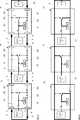
Die besonders hohe Flexibilität, die sich daraus ergibt, wird anhand der
An der Schnittstelle
In den
In der
Dies bedeutet, dass bei der ersten Schaltungsanordnung
Bei der zweiten Schaltungsanordnung
Die dritte Schaltungsanordnung
Die durch die entsprechende Konfiguration der einzelnen Schaltungsanordnungen
Aufgrund der vielfältigen Konfigurierbarkeit der Schaltungsanordnungen
In
In
In
Die Aktivierungsschaltergruppe S1 umfasst gemäß der Darstellung in
Darüber hinaus weist die Schaltungsanordnung
Ein weiteres besonderes Merkmal der Schaltungsanordnung
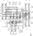
Ein vollständiges elektrisches Blockschaltbild der erfindungsgemäßen Schaltungsanordnung
Wie aus
Die Überbrückungsschaltergruppe S6 besteht ebenfalls aus jeweils einem Überbrückungsschalter S6_1, S6_2 pro Leitung, die zudem unabhängig voneinander geschaltet werden können, so dass jede Busleitung H, L entweder zwischen dem ersten Buseingang
Auch bei den Trennschaltergruppen S3, S4, ist jeweils ein Schalter, hier insbesondere ein Wechselschalter, für jede Busleitung H, L vorgesehen, so dass sowohl die erste Trennschaltergruppe S3 zwei Wechselschalter S3_1, S3_2, als auch die zweite Trennschaltergruppe S4, zwei Wechselschalter S4_1, S4_2 aufweist. Die Wechselschalter [S3_1, S3_2], [S4_1, S4_2] einer Trennschaltergruppe S3, S4 werden jeweils gemeinsam geschaltet.A switch, here in particular a changeover switch, is also provided for each bus line H, L in the case of the disconnect switch groups S3, S4, so that both the first disconnect switch group S3, two changeover switches S3_1, S3_2, and the second disconnect switch group S4, two changeover switches S4_1, S4_2 has. The changeover switches [S3_1, S3_2], [S4_1, S4_2] of a disconnect switch group S3, S4 are respectively switched together.
Die Terminierungseinheit
Eine alternative Ausgestaltung der Terminierungseinheit
Eine zweite Ausführungsvariante der erfindungsgemäßen Schaltungsanordnung
Die Schaltungsanordnung
Aufgrund der Anschlussmöglichkeit an den zweiten Bus
Auch eine dritte und vierte Trennschaltergruppe S8, S9 sind – wie für den ersten Bus
Schließlich weist die Schaltungsanordnung
Die erste Terminierungseinheit
Ein vollständiges elektrisches Blockschaltbild der zweiten Ausführungsvariante der erfindungsgemäßen Schaltungsanordnung zeigt
So umfasst die Aktivierungsschaltergruppe S1 vier einfache Schalter, nämlich einen Aktivierungsschalter S1_1H für den Signaleingang High und einen Aktivierungsschalter S1_1L für den Signaleingang Low sowie einen Aktivierungsschalter S1_2H für den Signalausgang High und einen Aktivierungsschalter S1_2L für den Signalausgang Low. Die derselben Busleitung H, L zugeordneten Schalter S1_1H, S1_2H einerseits und S1_1L, S1_2L andererseits bilden jeweils ein gemeinsam geschaltetes Paar.Thus, the activation switch group S1 comprises four simple switches, namely an activation switch S1_1H for the signal input High and an activation switch S1_1L for the signal input Low and an activation switch S1_2H for the signal output High and an activation switch S1_2L for the signal output Low. The same bus line H, L associated switches S1_1H, S1_2H on the one hand and S1_1L, S1_2L on the other hand each form a jointly connected pair.
Die Busumschaltergruppe S10 umfasst vier als Wechselschalter ausgeführte Busumschalter. Ein erster Busumschalter S10_1H verbindet wahlweise den High-Eingang des Busteilnehmers
Die erste Schaltergruppe S2 umfasst ebenfalls vier als Wechselschalter ausgeführte Schalter, die wahlweise zum ersten Buseingang
Einen zur ersten Schaltergruppe S2 identischen Aufbau weist die zweite Schaltergruppe S7 auf, umfassend die Wechselschalter S7_Hin, S7_Hout, S7_Lin und S7_Lout, wobei die Schalter der zweiten Schaltergruppe S7 die Verbindung zum zweiten Bus
Die oberen Busanschlüsse, d. h. der erste Buseingang
Zwischen den unteren Busanschlüssen, d. h. zwischen den zweiten Buseingängen
Die erste Trennschaltergruppe S3 umfasst einen ersten Trennschalter S3_1 für die High-Busleitung und einen zweiten Trennschalter S3_2 für die Low-Busleitung des ersten Busses
Die Trennschalter jeder Trennschaltergruppe S3, S4, S8, S9 werden gemeinsam geschaltet. Zusätzlich sind in der Ausführungsvariante nach
Schließlich umfasst die Schaltungsanordnung
Die zweite Terminierungseinheit
Die zu derselben Terminierungseinheit
Auch alle anderen Schalter sind in dem Ausführungsbeispiel nach
Die Aktivierungsschalter S1_1H, S1_2H, und S1_1L, S1_2L, die jeweils einer selben Busleitung High bzw. Low zugeordnet sind, sind jeweils durch ein Relais gemeinsam betätigt. Auch diese Relais sind unabhängig voneinander ansteuerbar. Auf diese Weise können der High-Eingang und Ausgang des Busteilnehmers, und sein Low-Eingang und Ausgang unabhängig voneinander getestet werden.The activation switches S1_1H, S1_2H, and S1_1L, S1_2L, which are each assigned to a same bus line High or Low, are each actuated jointly by a relay. These relays can also be controlled independently of each other. In this way, the high input and output of the bus device, and its low input and output can be tested independently.
Die Busumschalter S10_1H, S10_2H, und S10_1L, S10_2L, die jeweils einer selben Busleitung High bzw. Low zugeordnet sind, sind ebenfalls jeweils durch ein Relais gemeinsam betätigt. Die Ansteuerleitungen dieser Relais sind miteinander verbunden, so dass diese Relais gleichzeitig ansteuerbar sind. Dies reduziert den Ansteuerungsaufwand. Eine getrennte Ansteuerbarkeit ist hier nicht erforderlich, weil die High und Low Anschlüsse des Busteilnehmers stets am selben Bus angeschlossen sein müssen.The bus switches S10_1H, S10_2H, and S10_1L, S10_2L, which are each assigned to a same bus line High or Low, are also actuated in each case by a relay together. The control lines of these relays are connected to each other, so that these relays can be controlled simultaneously. This reduces the driving effort. A separate controllability is not required here, because the high and low connections of the bus station must always be connected to the same bus.
Bei der ersten Schaltergruppe S2 sind ebenfalls diejenigen Schalter [S2_Hin, S2_Hout] und [S2_Lin, S2_Lout] durch jeweils ein Relais gemeinsam betätigt, die mit einer selben Busleitung High/Low verbunden sind. Die Ansteuerleitungen dieser Relais sind miteinander verbunden, so dass diese Relais gleichzeitig ansteuerbar sind. Dasselbe gilt für die zweite Schaltergruppe S7. Hier sind ebenfalls diejenigen Schalter [S7_Hin, S7_Hout] und [S7_Lin, S7_Lout] durch jeweils ein Relais gemeinsam betätigt, die mit einer selben Busleitung High/Low verbunden sind. Die Ansteuerleitungen dieser Relais sind ebenfalls miteinander verbunden, so dass diese Relais gleichzeitig ansteuerbar sind. Zudem sind die Ansteuerleitungen der Relais der ersten und der zweiten Schaltergruppe S2, S7 zusammengeschaltet. Hierdurch wird ebenfalls der Ansteueraufwand (Leitungen, Anschlüsse, Signalverarbeitung) reduziert.In the case of the first switch group S2, those switches [S2_Hin, S2_Hout] and [S2_Lin, S2_Lout] are likewise actuated jointly by a respective relay which is connected to a same bus line High / Low. The control lines of these relays are connected to each other, so that these relays can be controlled simultaneously. The same applies to the second switch group S7. Here, too, the switches [S7_Hin, S7_Hout] and [S7_Lin, S7_Lout] are actuated by one relay in each case, which are connected to the same bus line High / Low. The control lines of these relays are also connected to each other, so that these relays can be controlled simultaneously. In addition, the drive lines of the relays of the first and the second switch group S2, S7 are interconnected. This also reduces the driving effort (lines, connections, signal processing).
Die Überbrückungsschalter sind alle einzeln betätigbar. Somit ist jedem Überbrückungsschalter ein eigenes Relais zugeordnet, die unabhängig voneinander ansteuerbar sind.The bypass switches are all individually operable. Thus, each bypass switch is assigned its own relay, which can be controlled independently of each other.
Schließlich besitzt jede Trennschaltergruppe S3, S4, S8, S9 ein eigenes Relais, das die zwei Trennschalter der entsprechenden Gruppe jeweils betätigt. Diejenigen Trennschaltergruppen, die für eine Terminierung derselben Seite verantwortlich sind, sind hier zusammenschaltet, d. h. gemeinsam angesteuert. Deren Ansteuerleitungen sind entsprechen miteinander verbunden. Dies gilt für die erste und dritte Trennschaltergruppe S3, S8 einerseits und die zweite und vierte Trennschaltergruppe S4, S9 andererseits.Finally, each disconnect switch group S3, S4, S8, S9 has its own relay which actuates the two disconnectors of the corresponding group respectively. Those disconnector groups that are responsible for a termination of the same page are here interconnected, ie jointly controlled. Their control lines are equal connected with each other. This applies to the first and third disconnect switch group S3, S8 on the one hand and the second and fourth disconnect switch group S4, S9 on the other hand.
In Summe umfasst die Ausführungsvariante in
Um die Stichleitung des CAN Busses möglichst kurz zu halten, wird hinter der Schnittstelle
Zu Beginn der Baumstruktur steht die Auswahl, ob der Busteilnehmer nur mit dem High-Anschluss (CAN_H) oder nur mit dem Low-Anschluss (CAN_L) oder sowohl mit dem High (CAN_H) als auch mit dem Low-Anschluss (CAN_H) angeschlossen werden soll. Diese Auswahl erfolgt mit den Aktivierungsschaltern.At the beginning of the tree structure, it is possible to select whether the bus subscriber is connected only with the high connection (CAN_H) or only with the low connection (CAN_L) or both with the high (CAN_H) and with the low connection (CAN_H) should. This selection is made with the activation switches.
Danach wird die Auswahl getroffen, ob der Busteilnehmer mit dem ersten oder zweiten Bus (CAN1 or CAN2) verbunden werden soll. Dies erfolgt über die Busumschalter.Then, the selection is made as to whether the bus subscriber is to be connected to the first or second bus (CAN1 or CAN2). This is done via the bus switch.
Sodann wird ausgewählt, ob die erfindungsgemäße Schaltungsanordnung
Für jeden der Busse kann der Busteilnehmer dann an den ersten Buseingang/ersten Busausgang, in
Nur für die Auswahl der Verbindung mit dem zweiten Buseingang und zweiten Busausgang ist schließlich zu wählen, ob eine rechtsseitige oder eine linksseitige Terminierung erfolgen soll, d. h. die Terminierungseinheit an dem zweiten Buseingang oder an dem zweiten Busausgang angeschlossen sein soll. Dies erfolgt über die Trennschalter.Finally, only for the selection of the connection with the second bus input and the second bus output is it to be decided whether a right-sided or a left-sided termination should take place, ie H. the termination unit is to be connected to the second bus input or to the second bus output. This is done via the disconnect switch.
In der
Dies bedeutet, dass bei der ersten Schaltungsanordnung
Bei der zweiten Schaltungsanordnung
Die dritte Schaltungsanordnung
Die Simulatoreinheit
Die durch die entsprechende Konfiguration der einzelnen Schaltungsanordnungen
In der
Dies bedeutet, dass bei der ersten Schaltungsanordnung
Bei der zweiten Schaltungsanordnung
Die dritte Schaltungsanordnung
Die Simulatoreinheit
Die durch die entsprechende Konfiguration der einzelnen Schaltungsanordnungen
Allen gezeigten Ausführungsvarianten liegt ein System zur Funktionsüberprüfung von Busteilnehmern ECU1, ECU2, ECU3 an einem Bus
Insbesondere im Hinblick auf die Ausführungsvarianten in
BezugszeichenlisteLIST OF REFERENCE NUMBERS
- 1, 1a, 1b, 1c1, 1a, 1b, 1c
- Schaltungsanordnungencircuitry
- 22
- Busteilnehmerbus users
- 33
- Erster Bus, CAN1First bus, CAN1
- 44
- Zweiter Bus, CAN2Second bus, CAN2
- 55
- Erster Buseingang für CAN1First bus input for CAN1
- 66
- Erster Busausgang für CAN1First bus output for CAN1
- 77
- Schnittstelle zu BusteilnehmerInterface to bus participant
- 88th
- Zweiter Buseingang für CAN1Second bus input for CAN1
- 99
- Zweiter Busausgang für CAN1Second bus output for CAN1
- 10, 101, 10210, 101, 102
- Terminierungseinheittermination unit
- 1111
- Erster Buseingang für CAN2First bus input for CAN2
- 1212
- Erster Busausgang für CAN2First bus output for CAN2
- 1313
- Zweiter Busausgang für CAN2Second bus output for CAN2
- 1414
- Zweiter Buseingang für CAN2Second bus input for CAN2
- 1515
- Knoten für Verbindung der ersten Schaltergruppe zum zweiten Buseingang und zweiten BusausgangNode for connecting the first switch group to the second bus input and second bus output
- 1616
- Bypassleitung CAN2Bypass line CAN2
- 1717
- Knoten für CAN2-TerminierungNode for CAN2 termination
- 1818
- Knoten für CAN1-TerminierungNode for CAN1 termination
- 1919
- Bypassleitung CAN1Bypass line CAN1
- 2020
- Simulatoreinheit/IOSimulator unit / IO
- 2121
- Toter BusabschnittDead bus section
- 2222
- Relaisanschlüsserelay connections
- S1S1
- AktivierungsschaltergruppeActivation switch group
- S1_1S1_1
- Aktivierungsschaltergruppe für BusteilnehmereingangActivation switch group for bus user input
- S1_1HS1_1H
- Aktivierungsschalter für Eingang HActivation switch for input H
- S1_1LS1_1L
- Aktivierungsschalter für Eingang LActivation switch for input L
- S1_2S1_2
- Aktivierungsschaltergruppe für BusteilnehmerausgangActivation switch group for bus subscriber output
- S1_2HS1_2H
- Aktivierungsschalter für Ausgang HActivation switch for output H
- S1_2LS1_2L
- Aktivierungsschalter für Ausgang LActivation switch for output L
- S2S2
- erste Schaltergruppe zur Auswahl des ersten Buseingang und Busausgangs oder zweiten Buseingangs und Busausgangs des ersten Bussesfirst switch group for selecting the first bus input and the bus output or the second bus input and the bus output of the first bus
- S2_HS2_H
- Wechselschalterpaar für die High BusleitungChangeover switch pair for the high bus line
- S2_HinS2_Hin
- Wechselschalter zur Auswahl des ersten Buseingangs H oder zweiten Buseingangs H (top/bottom)Changeover switch to select the first bus input H or the second bus input H (top / bottom)
- S2_HoutS2_Hout
- Wechselschalter zur Auswahl des ersten Busausgangs H oder zweiten Busausgangs H (top/bottom)Changeover switch for selecting the first bus output H or the second bus output H (top / bottom)
- S2_LS2_L
- Wechselschalterpaar für die Low BusleitungChangeover switch pair for the low bus line
- S2_LinS2_Lin
- Wechselschalter zur Auswahl des ersten Buseingangs L oder zweiten Buseingang L (top/bottom)Changeover switch for selecting the first bus input L or the second bus input L (top / bottom)
- S2_LoutS2_Lout
- Wechselschalter zur Auswahl des ersten Busausgangs L oder zweiten Busausgangs L (top/bottom)Changeover switch for selecting the first bus output L or the second bus output L (top / bottom)
- S3S3
- Trennschaltergruppe für zweiten Busausgang von CAN1Disconnector group for second bus output of CAN1
- S3_1S3_1
- Trennschalter für zweiten Busausgang H von CAN1Disconnector for second bus output H of CAN1
- S3_1S3_1
-
Trennschalter für zweiten Busausgang L von CAN 1Disconnector for second bus output L of
CAN 1 - S4S4
- Trennschaltergruppe für zweiten Buseingang von CAN1Disconnector group for second bus input of CAN1
- S4_1S4_1
- Trennschalter für zweiten Buseingang H von CAN1Disconnector for second bus input H of CAN1
- S4_1S4_1
- Trennschalter für zweiten Buseingang L von CAN1Disconnector for second bus input L of CAN1
- S5S5
- Terminierungsschalter/TerminierungsschaltergruppeTermination switch / terminating switch group
- S5_1S5_1
- Terminierungsschalter für CAN1Termination switch for CAN1
- S5_2S5_2
- Terminierungsschalter für CAN2Termination switch for CAN2
- S5_HS5_H
- Terminierungsschalter für H BusleitungTermination switch for H bus line
- S5_LS5_L
- Terminierungsschalter für L BusleitungTermination switch for L bus line
- S6S6
- Überbrückungsschaltergruppe zwischen erstem Buseingang und erstem Busausgang von CAN1Bypass switch group between first bus input and first bus output of CAN1
- S6_HS6_H
- Überbrückungsschalter für CAN1 HBridging switch for CAN1 H
- S6_LS6_L
- Überbrückungsschalter für CAN1 LBypass switch for CAN1 L
- S7S7
- erste Schaltergruppe zur Auswahl des ersten Buseingang und Busausgangs oder zweiten Buseingangs und Busausgangs des zweiten Bussesfirst switch group for selecting the first bus input and bus output or second bus input and bus output of the second bus
- S7_HinS7_Hin
- Wechselschalter zur Auswahl des ersten Buseingangs H oder zweiten Buseingangs H (top/bottom)Changeover switch to select the first bus input H or the second bus input H (top / bottom)
- S7_HoutS7_Hout
- Wechselschalter zur Auswahl des ersten Busausgangs H oder zweiten Busausgangs H (top/bottom)Changeover switch for selecting the first bus output H or the second bus output H (top / bottom)
- S7_LinS7_Lin
- Wechselschalter zur Auswahl des ersten Buseingangs L oder zweiten Buseingang L (top/bottom)Changeover switch for selecting the first bus input L or the second bus input L (top / bottom)
- S7_LoutS7_Lout
- Wechselschalter zur Auswahl des ersten Busausgangs L oder zweiten Busausgangs L (top/bottom)Changeover switch for selecting the first bus output L or the second bus output L (top / bottom)
- S8S8
- Trennschaltergruppe für zweiten Busausgang von CAN2Disconnector group for second bus output of CAN2
- S8_1S8_1
- Trennschalter für zweiten Busausgang H von CAN2Disconnector for second bus output H of CAN2
- S8_1S8_1
- Trennschalter für zweiten Busausgang L von CAN2Disconnector for second bus output L of CAN2
- S9S9
- Trennschaltergruppe für zweiten Buseingang von CAN2Disconnector group for second bus input of CAN2
- S9_1S9_1
- Trennschalter für zweiten Buseingang H von CAN2Disconnector for second bus input H of CAN2
- S9_1S9_1
- Trennschalter für zweiten Buseingang L von CAN2Disconnector for second bus input L of CAN2
- S10S10
- BusumschaltergruppeBusumschaltergruppe
- S10_1HS10_1H
- Busumschalter für Eingang HBus switch for input H
- S10_2HS10_2H
- Busumschalter für Ausgang HBus switch for output H
- S10_1LS10_1L
- Busumschalter für Eingang LBus switch for input L
- S10_2LS10_2L
- Busumschalter für Ausgang LBus switch for output L
- S11S11
- Überbrückungsschaltergruppe zwischen erstem Buseingang und erstem Busausgang von CAN2Bypass switch group between first bus input and first bus output of CAN2
- S11_HS11_H
- Überbrückungsschalter für CAN2 HBridging switch for CAN2 H
- S11_LS11_L
- Überbrückungsschalter für CAN2 LBridging switch for CAN2 L
Claims (19)
Priority Applications (3)
| Application Number | Priority Date | Filing Date | Title |
|---|---|---|---|
| DE201310100603 DE102013100603B3 (en) | 2013-01-22 | 2013-01-22 | Circuit arrangement for connecting electronic control unit to controller area network bus to test correct function of e.g. magnetic sensor of motor vehicle, has interface, where arrangement is bus-terminatingly configured at input or output |
| CN201410016033.5A CN103944794B (en) | 2013-01-22 | 2014-01-15 | Circuit device for being universally connected to bus user at least one bus |
| US14/161,064 US9772966B2 (en) | 2013-01-22 | 2014-01-22 | Circuit arrangement for universal connection of a bus participant to at least one bus |
Applications Claiming Priority (1)
| Application Number | Priority Date | Filing Date | Title |
|---|---|---|---|
| DE201310100603 DE102013100603B3 (en) | 2013-01-22 | 2013-01-22 | Circuit arrangement for connecting electronic control unit to controller area network bus to test correct function of e.g. magnetic sensor of motor vehicle, has interface, where arrangement is bus-terminatingly configured at input or output |
Publications (1)
| Publication Number | Publication Date |
|---|---|
| DE102013100603B3 true DE102013100603B3 (en) | 2014-05-15 |
Family
ID=50556130
Family Applications (1)
| Application Number | Title | Priority Date | Filing Date |
|---|---|---|---|
| DE201310100603 Active DE102013100603B3 (en) | 2013-01-22 | 2013-01-22 | Circuit arrangement for connecting electronic control unit to controller area network bus to test correct function of e.g. magnetic sensor of motor vehicle, has interface, where arrangement is bus-terminatingly configured at input or output |
Country Status (3)
| Country | Link |
|---|---|
| US (1) | US9772966B2 (en) |
| CN (1) | CN103944794B (en) |
| DE (1) | DE102013100603B3 (en) |
Cited By (5)
| Publication number | Priority date | Publication date | Assignee | Title |
|---|---|---|---|---|
| EP2990892A1 (en) * | 2014-09-01 | 2016-03-02 | dSPACE digital signal processing and control engineering GmbH | Method for connecting an input/output interface of a test device set up to test a control device |
| WO2018215289A1 (en) * | 2017-05-24 | 2018-11-29 | Wago Verwaltungsgesellschaft Mbh | Module unit for connecting a data bus participant |
| US10386806B2 (en) | 2015-09-01 | 2019-08-20 | Dspace Digital Signal Processing And Control Engineering Gmbh | Method for connecting models of technical systems in a testing device equipped for control unit development |
| DE102017012228B4 (en) * | 2017-05-24 | 2020-06-18 | Wago Verwaltungsgesellschaft Mbh | Module unit |
| DE102017012323B3 (en) * | 2017-05-24 | 2020-10-08 | Wago Verwaltungsgesellschaft Mbh | Modular unit |
Families Citing this family (9)
| Publication number | Priority date | Publication date | Assignee | Title |
|---|---|---|---|---|
| CN104506400A (en) * | 2014-11-12 | 2015-04-08 | 南京理工大学 | Wiring method for improving reliability of controller area network (CAN) bus and CAN bus system |
| EP3154220A1 (en) | 2015-10-09 | 2017-04-12 | Siemens Schweiz AG | Bus coupling unit and bus system comprising a bus coupling unit |
| FR3049416B1 (en) * | 2016-03-24 | 2021-10-22 | Peugeot Citroen Automobiles Sa | COMMUNICATION BODY OF A CAN NETWORK, WITH SPECIFIC IMPEDANCE |
| CN106487419B (en) * | 2016-11-18 | 2019-02-12 | 安徽江淮汽车集团股份有限公司 | A kind of multinode terminal resistance compartment system and method based on CANFD bus |
| FR3060917B1 (en) * | 2016-12-16 | 2019-05-17 | Peugeot Citroen Automobiles Sa | SPECIFIC IMPEDANCE COMMUNICATION DEVICE FOR A MULTIPLEX MULTIPLE BEAM NETWORK |
| CN108667674B (en) * | 2018-07-13 | 2021-06-29 | 中车大连机车车辆有限公司 | Dual network system and switching method |
| CN109557899B (en) * | 2018-11-05 | 2021-04-27 | 上海钧嵌传感技术有限公司 | CAN bus-based pressure controller of proportional valve for vehicle and communication method |
| DE102020121316A1 (en) * | 2020-08-13 | 2022-02-17 | Ebm-Papst Mulfingen Gmbh & Co. Kg | Unit for a bus system, master-slave bus system with a large number of units and method for addressing units in a bus system |
| US20240054089A1 (en) * | 2022-08-12 | 2024-02-15 | Hamilton Sundstrand Corporation | Signal reflection mitigation systems |
Citations (1)
| Publication number | Priority date | Publication date | Assignee | Title |
|---|---|---|---|---|
| EP2001169A1 (en) * | 2007-06-04 | 2008-12-10 | NEXTER Systems | Device for connecting components to a BUS line, BUS line and methods for regenerating a BUS line implementing such a connection device |
Family Cites Families (8)
| Publication number | Priority date | Publication date | Assignee | Title |
|---|---|---|---|---|
| US20020167899A1 (en) * | 2001-05-11 | 2002-11-14 | Thompson Richard A. | System and method for the configuration, repair and protection of virtual ring networks |
| US7385919B2 (en) * | 2002-02-22 | 2008-06-10 | Siemens Aktiengesellschaft | Local network, particularly Ethernet network having redundancy properties, and coupling device for such a network |
| JP4034782B2 (en) * | 2003-04-24 | 2008-01-16 | 富士通株式会社 | Ring connection device and data transfer control method |
| CN100370740C (en) * | 2004-03-06 | 2008-02-20 | 鸿富锦精密工业(深圳)有限公司 | Management method of stacked switch |
| DE102004055330A1 (en) * | 2004-11-16 | 2006-05-24 | Bosch Rexroth Aktiengesellschaft | Method and device for operating a network |
| JP4673712B2 (en) * | 2005-09-28 | 2011-04-20 | 富士通株式会社 | Network configuration apparatus and network configuration method |
| KR101468255B1 (en) * | 2010-11-22 | 2014-12-04 | 엘에스산전 주식회사 | PLC system |
| KR101720347B1 (en) * | 2011-01-20 | 2017-03-27 | 엘에스산전 주식회사 | Adaptive multi redundant ring topology system and Method for selecting the detour |
-
2013
- 2013-01-22 DE DE201310100603 patent/DE102013100603B3/en active Active
-
2014
- 2014-01-15 CN CN201410016033.5A patent/CN103944794B/en active Active
- 2014-01-22 US US14/161,064 patent/US9772966B2/en active Active
Patent Citations (1)
| Publication number | Priority date | Publication date | Assignee | Title |
|---|---|---|---|---|
| EP2001169A1 (en) * | 2007-06-04 | 2008-12-10 | NEXTER Systems | Device for connecting components to a BUS line, BUS line and methods for regenerating a BUS line implementing such a connection device |
Non-Patent Citations (3)
| Title |
|---|
| DIEKSTALL, K.; SCHÜTTE, H.; WÄLTERMANN, P.: Hardware-in-the-Loop-Test verteilter Kfz-Elektroniksysteme. In ATZ - Automobiltechnische Zeitschrift, 2004, Nr. 4, S. 416-425. - ISSN 0001-2785 * |
| JANSSEN, Dirk; BÜTTNER, Holger: EtherCAT - Der Ethernet-Feldbus. In Elektronik, 2003, Nr. 23, S. 64-72 und Nr. 25, S. 62-67. - ISSN 0013-5658 * |
| JANSSEN, Dirk; BÜTTNER, Holger: EtherCAT – Der Ethernet-Feldbus. In Elektronik, 2003, Nr. 23, S. 64-72 und Nr. 25, S. 62-67. - ISSN 0013-5658 |
Cited By (9)
| Publication number | Priority date | Publication date | Assignee | Title |
|---|---|---|---|---|
| EP2990892A1 (en) * | 2014-09-01 | 2016-03-02 | dSPACE digital signal processing and control engineering GmbH | Method for connecting an input/output interface of a test device set up to test a control device |
| US9772918B2 (en) | 2014-09-01 | 2017-09-26 | Dspace Digital Signal Processing And Control Engineering Gmbh | Method for connecting an input/output interface of a testing device equipped for testing a control unit |
| US10386806B2 (en) | 2015-09-01 | 2019-08-20 | Dspace Digital Signal Processing And Control Engineering Gmbh | Method for connecting models of technical systems in a testing device equipped for control unit development |
| WO2018215289A1 (en) * | 2017-05-24 | 2018-11-29 | Wago Verwaltungsgesellschaft Mbh | Module unit for connecting a data bus participant |
| DE102017012228B4 (en) * | 2017-05-24 | 2020-06-18 | Wago Verwaltungsgesellschaft Mbh | Module unit |
| DE102017012323B3 (en) * | 2017-05-24 | 2020-10-08 | Wago Verwaltungsgesellschaft Mbh | Modular unit |
| US11411767B2 (en) | 2017-05-24 | 2022-08-09 | Wago Verwaltungsgesellschaft Mbh | Module unit for connecting a data bus subscriber |
| EP4191954A1 (en) * | 2017-05-24 | 2023-06-07 | WAGO Verwaltungsgesellschaft mbH | Module unit for connecting a data bus participant |
| US11936497B2 (en) | 2017-05-24 | 2024-03-19 | Wago Verwaltungsgesellschaft Mbh | Module unit for connecting a data bus subscriber |
Also Published As
| Publication number | Publication date |
|---|---|
| US20140207994A1 (en) | 2014-07-24 |
| CN103944794B (en) | 2018-09-25 |
| CN103944794A (en) | 2014-07-23 |
| US9772966B2 (en) | 2017-09-26 |
Similar Documents
| Publication | Publication Date | Title |
|---|---|---|
| DE102013100603B3 (en) | Circuit arrangement for connecting electronic control unit to controller area network bus to test correct function of e.g. magnetic sensor of motor vehicle, has interface, where arrangement is bus-terminatingly configured at input or output | |
| EP1540428B1 (en) | Redundant control unit arrangement | |
| DE602006000615T2 (en) | Ethernet network with redundancy implementation using a single Category 5 cable | |
| EP2588928B1 (en) | Communication system for connecting field devices to an overlaid control device | |
| EP2087646B1 (en) | Device and method for manipulating communication messages | |
| EP0952704A2 (en) | Electronic vehicle control device with bus interface | |
| DE102006055887A1 (en) | Communication system with a master-slave structure | |
| EP0939922A1 (en) | Device and method for controlling machines especially a power loom | |
| DE102016000126A1 (en) | Serial bus system with coupling modules | |
| EP3491472A1 (en) | Series module, connection module and control arrangement having a modular design | |
| EP2217475A1 (en) | Device for the electric actuation of a safety-critical system | |
| EP3360284B1 (en) | Bus coupling unit and bus system comprising a bus coupling unit | |
| EP1603282A1 (en) | Method for addressing subscribers of a bus system | |
| EP2369694B1 (en) | Connection device and automation device | |
| WO2013004383A1 (en) | Communication interface module for an automation system | |
| DE60319175T2 (en) | Data transmission system in the vehicle with redundant connections | |
| EP3834388B1 (en) | Line driver device for data flow control | |
| DE102005056284A1 (en) | Method of making a network formed of buses of the CAN type, network and devices with this network | |
| EP1898551B1 (en) | Apparatus comprising a system interface | |
| DE102017216284A1 (en) | communication system | |
| DE102011115431B4 (en) | Fieldbus network adapters and fieldbus network participants with fieldbus connections | |
| DE10324724A1 (en) | Control device with redundant CAN data bus e.g. for communication systems, has additional CAN data bus segment as redundant data bus segment provided between data bus terminals | |
| DE102011118361A1 (en) | Device for controlling multiple drive units for controlled drive system for automated system, has central control device and distributor unit, which has connection for transmitting control signal | |
| DE102011118360A1 (en) | Device for controlling drive units in controlled drive system for packaging machine, has interface connected with uncoupling device for decoupling control signal of input of peripheral control unit to peripheral devices | |
| EP4295544A1 (en) | Single-pair ethernet switching apparatus |
Legal Events
| Date | Code | Title | Description |
|---|---|---|---|
| R012 | Request for examination validly filed | ||
| R016 | Response to examination communication | ||
| R016 | Response to examination communication | ||
| R018 | Grant decision by examination section/examining division | ||
| R020 | Patent grant now final | ||
| R020 | Patent grant now final |
Effective date: 20150217 |
|
| R081 | Change of applicant/patentee |
Owner name: DSPACE GMBH, DE Free format text: FORMER OWNER: DSPACE DIGITAL SIGNAL PROCESSING AND CONTROL ENGINEERING GMBH, 33102 PADERBORN, DE |