EP1603282A1 - Method for addressing subscribers of a bus system - Google Patents
Method for addressing subscribers of a bus system Download PDFInfo
- Publication number
- EP1603282A1 EP1603282A1 EP04013060A EP04013060A EP1603282A1 EP 1603282 A1 EP1603282 A1 EP 1603282A1 EP 04013060 A EP04013060 A EP 04013060A EP 04013060 A EP04013060 A EP 04013060A EP 1603282 A1 EP1603282 A1 EP 1603282A1
- Authority
- EP
- European Patent Office
- Prior art keywords
- switch
- subscribers
- central control
- control unit
- participants
- Prior art date
- Legal status (The legal status is an assumption and is not a legal conclusion. Google has not performed a legal analysis and makes no representation as to the accuracy of the status listed.)
- Granted
Links
- 238000000034 method Methods 0.000 title claims abstract description 97
- 238000004891 communication Methods 0.000 claims description 16
- 102100036285 25-hydroxyvitamin D-1 alpha hydroxylase, mitochondrial Human genes 0.000 claims description 10
- 101000875403 Homo sapiens 25-hydroxyvitamin D-1 alpha hydroxylase, mitochondrial Proteins 0.000 claims description 10
- 230000006399 behavior Effects 0.000 claims description 8
- 238000001514 detection method Methods 0.000 claims description 5
- 230000004044 response Effects 0.000 claims description 5
- 238000004458 analytical method Methods 0.000 claims description 2
- 230000004913 activation Effects 0.000 claims 6
- 230000009849 deactivation Effects 0.000 claims 6
- 230000003111 delayed effect Effects 0.000 claims 2
- 230000001771 impaired effect Effects 0.000 claims 2
- 239000004065 semiconductor Substances 0.000 claims 2
- 230000001960 triggered effect Effects 0.000 claims 2
- 238000005259 measurement Methods 0.000 description 2
- 210000003462 vein Anatomy 0.000 description 2
- 101100390736 Danio rerio fign gene Proteins 0.000 description 1
- 101100390738 Mus musculus Fign gene Proteins 0.000 description 1
- 238000004378 air conditioning Methods 0.000 description 1
- 238000010276 construction Methods 0.000 description 1
- 230000001419 dependent effect Effects 0.000 description 1
- 238000011161 development Methods 0.000 description 1
- 238000005516 engineering process Methods 0.000 description 1
- 238000011156 evaluation Methods 0.000 description 1
- 230000007257 malfunction Effects 0.000 description 1
- 238000004519 manufacturing process Methods 0.000 description 1
- 238000000926 separation method Methods 0.000 description 1
- 230000003068 static effect Effects 0.000 description 1
- 238000011144 upstream manufacturing Methods 0.000 description 1
Images


Classifications
-
- G—PHYSICS
- G06—COMPUTING; CALCULATING OR COUNTING
- G06F—ELECTRIC DIGITAL DATA PROCESSING
- G06F12/00—Accessing, addressing or allocating within memory systems or architectures
- G06F12/02—Addressing or allocation; Relocation
- G06F12/06—Addressing a physical block of locations, e.g. base addressing, module addressing, memory dedication
- G06F12/0646—Configuration or reconfiguration
- G06F12/0653—Configuration or reconfiguration with centralised address assignment
- G06F12/0661—Configuration or reconfiguration with centralised address assignment and decentralised selection
-
- H—ELECTRICITY
- H04—ELECTRIC COMMUNICATION TECHNIQUE
- H04L—TRANSMISSION OF DIGITAL INFORMATION, e.g. TELEGRAPHIC COMMUNICATION
- H04L61/00—Network arrangements, protocols or services for addressing or naming
- H04L61/50—Address allocation
- H04L61/5092—Address allocation by self-assignment, e.g. picking addresses at random and testing if they are already in use
-
- H—ELECTRICITY
- H04—ELECTRIC COMMUNICATION TECHNIQUE
- H04L—TRANSMISSION OF DIGITAL INFORMATION, e.g. TELEGRAPHIC COMMUNICATION
- H04L12/00—Data switching networks
- H04L12/28—Data switching networks characterised by path configuration, e.g. LAN [Local Area Networks] or WAN [Wide Area Networks]
- H04L12/40—Bus networks
- H04L12/40006—Architecture of a communication node
- H04L12/40032—Details regarding a bus interface enhancer
-
- H—ELECTRICITY
- H04—ELECTRIC COMMUNICATION TECHNIQUE
- H04L—TRANSMISSION OF DIGITAL INFORMATION, e.g. TELEGRAPHIC COMMUNICATION
- H04L12/00—Data switching networks
- H04L12/28—Data switching networks characterised by path configuration, e.g. LAN [Local Area Networks] or WAN [Wide Area Networks]
- H04L12/40—Bus networks
- H04L2012/40267—Bus for use in transportation systems
- H04L2012/40273—Bus for use in transportation systems the transportation system being a vehicle
Definitions
- the invention relates to a method for addressing (any number) of participants of a bus system with a control unit, one of the Control unit outgoing bus and several participants, each other following connected to the bus, as a further development of DE 101 47 512 A1 proposed method.
- the control signals for driving actuators via a bus to send in addition to a control unit and the control units connected for the actuator devices of the individual participants are.
- the actuator devices are grouped together to form a bus system a vehicle air conditioning, the windows or the front vehicle seats.
- the control unit selectively one or more Actuate actuators are assigned to these addresses. So far the participants their addresses e.g. stored by programming or assigned by plug-in or PIN coding. While programming is still relatively unproblematic in the production of a vehicle, this requires if the entire subscriber, that is the actuator device with control, for example, replaced in a workshop is, so far an increased effort.
- a central control unit sends a short-circuit signal to close the short-circuit switch of all not yet addressed Participants out. Subsequently, a measuring current is impressed, which in the first from the control center (ie in the next to the headquarters arranged) participants of the group not yet addressed participants to cause a voltage drop. Subsequently, on the primary alarm line put an address data signal. The one participant who still no address has been assigned and the previously a voltage drop detected, takes this address data signal in its address memory. Subsequently, the assignment of the Short-circuit signal, wherein the short-circuit switch of the previously addressed subscriber not closed, but rather the short-circuit switch all previously not addressed participants are addressed.
- this known method is based on Reason of the short circuit of the two veins of the primary reporting line the entire Measuring current via the short-circuit switch of the closest to the central control unit arranged participant of the group from not yet addressed Participants flows.
- electronic switches as they have be used as a short-circuit switch according to the known method, however, a non-negligible on-resistance. Consequently, so flows also a part of the measuring current via the short-circuit switch of the neighboring not yet addressed subscriber and generates about its resistances also a voltage drop. So it's not just the circumstance that a voltage drop is detected to detect, but also the Size of this voltage drop to detect.
- German patent application DE 101 47 512 A1 proposes a method which eliminates the problems described in DE 40 38 992 C2. In a certain embodiment, however, results in these known methods the problem of relatively high bus currents. These arise, when the pullup 30 or pulldown 40 of the central control unit 14 of lower impedance is, as the common resistance of all switches 26 all Participants 1 through 9. Although in Figs. 1 to 13 not shown separately, is in DE 40 38 992 C2 described this switch 26 as a switchable resistor. The well-known principle is based on this fact.
- open switch results from the first-time response of the detector, why above and hereinafter with “open switch” is meant that the Detector has addressed. This is one of the participants from the group all participants specified so that this participant now has a Address can be given. During further addressing cycles will now open the same way with the other participants proceed, the switch of the already addressed subscriber always remains open.
- the static total current of the controllable switches of all subscribers may be dimensioned to be higher than the current that the resistor or the current source of the central control unit can supply.
- the current through a controllable switch can be greater than the current flowing through the central control unit divided by the number of participants. So it applies I (27)> I (30) / n, where I (27) is the current through the controllable switch, I (30) is the current through the resistor or the current source, and n is the number of subscribers (see the attached figure).
- the useful signal to be used for the addressing namely the greater by the detectors to be detected currents. Consequently, can be produce the detectors themselves cheaper because they do not have to be so sensitive. Furthermore, the susceptibility of the addressing method according to the invention improved.
- the resistance involved in the process is formed by a switch necessary for the bus communication, the is controllable, is opposite to the realization of the method according to the invention a normal bus no additional component required what the effort regarding the implementation of the procedure in an existing one Simplified bus system.
- Is the shunt resistor an analog / digital converter connected downstream and as a comparator uses a digital comparator, so can the threshold depending on the application and depending on operating conditions such as Parameterize supply voltage, temperature and number of participants.
- the inventive method does not need to all participants of the Bussystems be applied. Also, the participants can count on it is applied, located at any point / points of the bus system. With In other words, the bus system at any point / places participants which do not participate in the addressing process according to the invention, but then do not disturb it. These participants can then go to one other than the inventive type are addressed.
- Modules of the central control unit either individually or together or double, namely once per bus connection are designed, which makes both sides the bus line for analysis or in case of error (for example, open Plug contact) can be operated by the central unit.
Landscapes
- Engineering & Computer Science (AREA)
- Theoretical Computer Science (AREA)
- Computer Networks & Wireless Communication (AREA)
- Signal Processing (AREA)
- Physics & Mathematics (AREA)
- General Engineering & Computer Science (AREA)
- General Physics & Mathematics (AREA)
- Telephonic Communication Services (AREA)
- Small-Scale Networks (AREA)
- Exchange Systems With Centralized Control (AREA)
- Dc Digital Transmission (AREA)
Abstract
Description
Die Erfindung betrifft ein Verfahren zur Adressierung (einer beliebigen Anzahl) von Teilnehmern eines Bussystems mit einer Steuereinheit, einem von der Steuereinheit ausgehenden Bus und mehreren Teilnehmern, die aufeinander folgend an den Bus angeschlossen sind, als Weiterentwicklung des in DE 101 47 512 A1 vorgeschlagenen Verfahrens.The invention relates to a method for addressing (any number) of participants of a bus system with a control unit, one of the Control unit outgoing bus and several participants, each other following connected to the bus, as a further development of DE 101 47 512 A1 proposed method.
Um den Verdrahtungsaufwand beispielsweise im Kfz zu minimieren, geht man dazu über, die Steuersignale zum Ansteuern von Stellgliedern über einen Bus zu versenden, an dem neben einer Steuereinheit auch die Ansteuereinheiten für die Stellantriebsvorrichtungen der einzelnen Teilnehmer angeschlossen sind. Zu einem Bussystem zusammengefasst sind beispielsweise die Stellantriebsvorrichtungen einer Fahrzeug-Klimaanlage, der Fensterheber oder der vorderen Fahrzeugsitze. Damit die Steuereinheit selektiv ein oder mehrere Stellantriebe ansteuern kann, sind diesen Adressen zugeordnet. Bisher werden den Teilnehmern ihre Adressen z.B. durch Programmierung eingespeichert oder durch Steck- oder PIN-Kodierung zugeordnet. Während das Programmieren bei der Fertigung eines Fahrzeugs noch relativ unproblematisch ist, erfordert dies dann, wenn der gesamte Teilnehmer, das heißt die Stellantriebsvorrichtung mit Ansteuerung, beispielsweise in einer Werkstatt ausgetauscht wird, insoweit einen erhöhten Aufwand. Ferner besteht bezüglich der Logistik das Erfordernis der Einhaltung definierter Bestückungsreihenfolgen mit der damit verbundenen Serviceunfreundlichkeit bzw. der Lieferung vorprogrammierter (voradressierter) Bauteile, was dem Gleichteileprinzip zuwiderläuft. Außerdem kann es bei der Steckerkodierung zu Funktionsstörungen kommen. Schließlich ist es auch möglich, die Selbstadressierung der Teilnehmer eines Bussystems über Schalter zum seriellen Trennen der Bus-Verbindungen zwischen den Teilnehmern zu realisieren. Hier sind als Nachteile insbesondere die elektrische Auftrennung der Bus-Leitung über aktive Bauelemente und der hohe Flächenbedarf für Bussysteme mit vielen Teilnehmern zu nennen.To minimize the wiring, for example, in the car, you go about, the control signals for driving actuators via a bus to send, in addition to a control unit and the control units connected for the actuator devices of the individual participants are. For example, the actuator devices are grouped together to form a bus system a vehicle air conditioning, the windows or the front vehicle seats. Thus, the control unit selectively one or more Actuate actuators are assigned to these addresses. So far the participants their addresses e.g. stored by programming or assigned by plug-in or PIN coding. While programming is still relatively unproblematic in the production of a vehicle, this requires if the entire subscriber, that is the actuator device with control, for example, replaced in a workshop is, so far an increased effort. Furthermore, regarding the Logistics the requirement of compliance with defined placement sequences with the service unfriendliness or the delivery preprogrammed (pre-addressed) components, which runs counter to the common parts principle. In addition, it may be in the connector coding to malfunction come. Finally, it is also possible to self-address the participants a bus system via switches for the serial disconnection of the bus connections to realize between the participants. Here are as disadvantages in particular the electrical separation of the bus line via active components and to mention the large space requirement for bus systems with many subscribers.
Automatisierte Adressvergabeverfahren für Bussysteme sind aus EP 0 854 609 A1, DE 196 47 668 A1, DE 44 04 962 C2, DE 44 28 502 A1, WO 97/45983 A1 und DE 197 56 564 A1 bekannt.Automated address allocation methods for bus systems are described in EP 0 854 609 A1, DE 196 47 668 A1, DE 44 04 962 C2, DE 44 28 502 A1, WO 97/45983 A1 and DE 197 56 564 A1.
Aus DE 40 38 992 C2 schließlich ist ein Verfahren bekannt, bei dem die Adressen der Komponenten einer Gefahrenmeldeanlage automatisch zugeordnet werden. Die Adressierung erfolgt dabei ausgehend von dem zur Zentrale nächstgelegenen Teilnehmer bis zu dem von der Zentrale am entferntesten angeordneten Teilnehmer. Jeder Teilnehmer weist dabei in jeder der beiden Adern einer Meldeprimärleitung jeweils einen Widerstand und zwischen den beiden Adern mehrere elektrische und elektronische Bauteile auf. Ferner ist jeder Teilnehmer mit einem Kurzschlussschalter versehen, um die beiden Adern kurzzuschließen. Bei kurzgeschlossenem Schalter kann der sich über die beiden zuvor genannten Widerstände ergebende Spannungsabfall (bei Aufprägung eines Messstroms auf der Meldeprimärleitung) messtechnisch ermittelt werden. Sämtliche dieser Teilnehmer sind seriell in der Meldeprimärleitung angeordnet.From DE 40 38 992 C2, finally, a method is known in which the addresses the components of a hazard alarm system automatically assigned become. The addressing takes place starting from that to the control center nearest participant to that of the center furthest arranged participants. Each participant points in each of the two Wires of a primary alarm line each have a resistance and between the Both wires on several electrical and electronic components. Further is each participant provided with a short-circuit switch to the two Short circuit wires. With a short-circuited switch can be on the both aforementioned resistances resulting voltage drop (at imprint a measuring current on the primary alarm line) by measurement become. All of these subscribers are arranged serially in the primary reporting line.
Zu Beginn der Adressierung sendet eine Zentralsteuereinheit ein Kurzschlusssignal zum Schließen der Kurzschlussschalter sämtlicher noch nicht adressierter Teilnehmer aus. Im Anschluss daran wird ein Messstrom aufgeprägt, der in dem von der Zentrale aus betrachtet ersten (also in dem zur Zentrale nächst angeordneten) Teilnehmer der Gruppe noch nicht adressierter Teilnehmer einen Spannungsabfall hervorrufen soll. Anschließend wird auf die Meldeprimärleitung ein Adressdatensignal gelegt. Derjenige Teilnehmer, dem noch keine Adresse zugeordnet worden ist und der zuvor einen Spannungsabfall detektiert hat, übernimmt dieses Adressdatensignal in seinen Adressspeicher. Anschließend erfolgt zur weiteren Adressierung wiederum die Vergabe des Kurzschlusssignals, wobei der Kurzschlussschalter des zuvor adressierten Teilnehmers nicht geschlossen wird, sondern vielmehr die Kurzschlussschalter sämtlicher bis dahin noch nicht adressierter Teilnehmer angesprochen werden. Beim Aufprägen des Messstroms erzeugt dieser dann in dem nunmehr zur Zentralsteuereinheit am nächsten angeordneten Teilnehmer der Gruppe aus noch nicht adressierten Teilnehmern einen zu detektierenden Spannungsabfall, so dass dieser Teilnehmer in der nächsten Phase, in der auf die Meldeprimärleitung wiederum ein Adressdatensignal gelegt wird, diese Adresse in seinem Adressspeicher abgelegt und somit ebenfalls adressiert ist. Dieses Verfahren wird fortgesetzt, bis der letzte Teilnehmer adressiert ist.At the beginning of the addressing, a central control unit sends a short-circuit signal to close the short-circuit switch of all not yet addressed Participants out. Subsequently, a measuring current is impressed, which in the first from the control center (ie in the next to the headquarters arranged) participants of the group not yet addressed participants to cause a voltage drop. Subsequently, on the primary alarm line put an address data signal. The one participant who still no address has been assigned and the previously a voltage drop detected, takes this address data signal in its address memory. Subsequently, the assignment of the Short-circuit signal, wherein the short-circuit switch of the previously addressed subscriber not closed, but rather the short-circuit switch all previously not addressed participants are addressed. When imprinting the measuring current generates this then in the now Central control unit closest to the group participants participants not yet addressed a voltage drop to be detected, so that this participant in the next phase, in the on the primary reporting line again an address data signal is placed, this address in his Address memory stored and thus also addressed. This method continues until the last station is addressed.
Bei diesem bekannten Verfahren wird idealisiert davon ausgegangen, dass auf Grund des Kurzschlusses der beiden Adern der Meldeprimärleitung der gesamte Messstrom über den Kurzschlussschalter des am nächsten zur Zentralsteuereinheit angeordneten Teilnehmers der Gruppe aus noch nicht adressierten Teilnehmern fließt. In der Praxis weisen elektronische Schalter, wie sie gemäß dem bekannten Verfahren als Kurzschlussschalter eingesetzt werden, jedoch einen nicht zu vernachlässigenden Ein-Widerstand auf. Mithin fließt also auch ein Teil des Messstroms über den Kurzschlussschalter des benachbarten noch nicht adressierten Teilnehmers und erzeugt über dessen Widerständen ebenfalls einen Spannungsabfall. Es ist also erforderlich, nicht nur den Umstand, dass ein Spannungsabfall detektiert ist, zu erfassen, sondern auch die Größe dieses Spannungsabfalls zu detektieren. Darüber hinaus ist zu bedenken, dass, je weiter ein noch nicht adressierter Teilnehmer von der Zentralsteuereinheit angeordnet ist, der Messstrom und damit der detektierbare Spannungsabfall sich verringert, was allein schon daran liegt, dass der Messstrom, der über den geschlossenen Kurzschlussschalter eines relativ weit von der Zentralsteuereinheit angeordneten Teilnehmers über die in den Adern der Meldeprimärleitung angeordneten Widerstände der diesem Teilnehmer vorgeschalteten, bereits adressierten Teilnehmer fließen muss. Die Auswertung und die zuverlässige Detektierung der Spannungsabfälle bei dem bekannten Verfahren ist also nicht trivial, was schaltungstechnischen und Programmieraufwand mit sich bringt. Ideally, this known method is based on Reason of the short circuit of the two veins of the primary reporting line the entire Measuring current via the short-circuit switch of the closest to the central control unit arranged participant of the group from not yet addressed Participants flows. In practice, electronic switches, as they have be used as a short-circuit switch according to the known method, however, a non-negligible on-resistance. Consequently, so flows also a part of the measuring current via the short-circuit switch of the neighboring not yet addressed subscriber and generates about its resistances also a voltage drop. So it's not just the circumstance that a voltage drop is detected to detect, but also the Size of this voltage drop to detect. In addition, it should be remembered that, the further a not yet addressed subscriber from the central control unit is arranged, the measuring current and thus the detectable Voltage drop is reduced, which is due to the fact that the measuring current, the over the closed short-circuit switch of a relatively far from the central control unit arranged subscriber via the in the veins of the Primary alarm line arranged resistors of this participant upstream, already addressed participants must flow. The evaluation and the reliable detection of the voltage drops in the known method So it is not trivial, what circuitry and programming brings with it.
In der deutschen Patentanmeldung DE 101 47 512 A1 ist ein Verfahren vorgeschlagen
worden, welches die zu DE 40 38 992 C2 dargelegten Probleme beseitigt.
In einer bestimmten Ausführungsvariante ergibt sich jedoch bei diesen
bekannten Verfahren das Problem von relativ hohen BUS-Strömen. Diese entstehen,
wenn der Pullup 30 oder Pulldown 40 der Zentralsteuereinheit 14 niederohmiger
ist, als der gemeinschaftliche Widerstand aller Schalter 26 aller
Teilnehmer 1 bis 9. Obwohl in Fign. 1 bis 13 nicht gesondert dargestellt, ist in
DE 40 38 992 C2 dieser Schalter 26 als schaltbarer Widerstand beschrieben.
Auf dieser Tatsache beruht ja das bekannte Prinzip.German patent application DE 101 47 512 A1 proposes a method
which eliminates the problems described in
In der Praxis wird der Pullup bzw. Pulldown der Zentralsteuereinheit eine Strombegrenzung durch Stromquellenverhalten oder Widerstand aufweisen.In practice, the pullup or pulldown of the central control unit becomes a Current limitation due to current source behavior or resistance.
In den Fign. der DE 40 38 992 C2 ist der Pullup bzw. Pulldown als Widerstand dargestellt. Damit ergibt sich die Notwendigkeit, den Einzelstrom in jedem Teilnehmer kleiner zu dimensionieren, als den Wert der Strombegrenzung der Zentralsteuereinheit geteilt durch die Anzahl der Teilnehmer. Der zur Generierung eines Nutzsignals zur Verfügung stehende Messstrom ist damit erstens so klein, dass trotz hohen Aufwandes für Messtechnik nur mit störbehafteten Messungen zu rechnen ist. Zweitens ist dieser maximal nutzbare Messstrom abhängig von der Anzahl der Bus-Teilnehmer.In the Fign. DE 40 38 992 C2 is the pullup or pulldown as a resistor shown. This results in the need to use the single stream in each To dimension subscribers smaller than the value of the current limit of Central control unit divided by the number of participants. The for generation of a useful signal available measuring current is thus firstly so small that despite high expenditure for measuring technology only with interference-prone Measurements can be expected. Second, this maximum usable measuring current depending on the number of bus participants.
Zur Lösung dieser Aufgabe wird mit der Erfindung ein Verfahren gemäß einem der selbständigen Ansprüche vorgeschlagen, wobei einzelne Ausführungsbeispiele in den Unteransprüchen angegeben sind.To solve this problem with the invention, a method according to a the independent claims proposed, with individual embodiments are specified in the dependent claims.
Bei dem Verfahren zum Adressieren der Teilnehmer eines Bussystems legt die Zentralsteuereinheit die Busleitung gegen eine Seite der Betriebsspannung, während jeder Teilnehmer versucht, die Busleitung auf ein Referenzpotential, üblicherweise die Betriebsspannung, zu ziehen, wobei aufgrund des Stromquellenverhaltens des den Bus auf Betriebsspannung legenden Schalters durch einen dem Teilnehmer zugeordneten Detektor in der Busleitung ein Strom detektierbar ist. Wenn der Teilnehmer diesen Stromabfall detektiert, schaltet er seinen Schalter aus. Durch ein zeitlich definiertes langsames Zuschalten der geschalteten Stromquellen spielt sich dieser Vorgang innerhalb einer Gruppe von Teilnehmern sequenziell ab, bis der letzte Teilnehmer erreicht ist. Von dem diesem Teilnehmer zugeordneten Detektor wird in jedem Fall kein Strom detektiert, so dass nach Ablauf einer vorgebbaren Einschaltzeitspanne der Schalter dieses Teilnehmers noch geöffnet ist. Der Zustand "geöffneter Schalter" ergibt sich aus dem erstmaligen Ansprechen des Detektors, weshalb vorstehend und nachfolgend mit "geöffneter Schalter" gemeint ist, dass der Detektor angesprochen hat. Damit ist einer der Teilnehmer aus der Gruppe sämtlicher Teilnehmer spezifiziert, so dass diesem Teilnehmer nunmehr eine Adresse zuteil werden kann. Während weiterer Adressierzyklen wird nun auf die gleiche Weise mit den übrigen Teilnehmern verfahren, wobei der Schalter des bereits adressierten Teilnehmers stets offen bleibt.In the method for addressing the subscribers of a bus system sets the Central control unit the bus line against one side of the operating voltage, while each participant tries to connect the bus line to a reference potential, usually the operating voltage to pull, due to the current source behavior of the bus laying on operating voltage switch through a detector associated with the subscriber in the bus line a stream is detectable. If the subscriber detects this current drop, switches he turned off his switch. Through a timely defined slow connection of the switched current sources, this process takes place within a group from subscribers sequentially until the last subscriber is reached. From the detector associated with this subscriber will in any case not be powered detected, so that after expiry of a predefinable switch-on of the Switch of this subscriber is still open. The state "open switch" results from the first-time response of the detector, why above and hereinafter with "open switch" is meant that the Detector has addressed. This is one of the participants from the group all participants specified so that this participant now has a Address can be given. During further addressing cycles will now open the same way with the other participants proceed, the switch of the already addressed subscriber always remains open.
Insbesondere ist bei dem erfindungsgemäßen Verfahren von Vorteil, dass der
statische Summenstrom der steuerbaren Schalter sämtlicher Teilnehmer höher
dimensioniert sein darf als derjenige Strom, den der Widerstand bzw. die
Stromquelle der Zentralsteuereinheit liefern kann. Mit anderen Worten kann
also der Strom durch einen steuerbaren Schalter größer sein als der über die
Zentralsteuereinheit abfließende Strom geteilt durch die Anzahl der Teilnehmer.
Es gilt also
Dadurch wird das für die Adressierung zu verwendende Nutzsignal, nämlich die durch die Detektoren zu erkennenden Ströme größer. Demzufolge lassen sich die Detektoren selbst günstiger produzieren, da sie nicht so sensibel sein müssen. Ferner wird die Störempfindlichkeit des erfindungsgemäßen Adressierverfahrens verbessert.As a result, the useful signal to be used for the addressing, namely the greater by the detectors to be detected currents. Consequently, can be produce the detectors themselves cheaper because they do not have to be so sensitive. Furthermore, the susceptibility of the addressing method according to the invention improved.
Dadurch, dass gemäß der Erfindung der am Verfahren beteiligte Widerstand durch einen für die Buskommunikation notwendigen Schalter gebildet ist, der steuerbar ist, ist zur Realisierung des erfindungsgemäßen Verfahrens gegenüber einem normalen Bus kein zusätzliches Bauteil erforderlich, was den Aufwand bezüglich der Implementierung des Verfahrens in einem bestehenden Bussystem vereinfacht.Because, according to the invention, the resistance involved in the process is formed by a switch necessary for the bus communication, the is controllable, is opposite to the realization of the method according to the invention a normal bus no additional component required what the effort regarding the implementation of the procedure in an existing one Simplified bus system.
Bei der Variante der Erfindung gemäß Anspruch 8 gilt, dass die zur Stromdetektion
benutzten Shunt-Widerstände der Detektoren relativ hochohmig sein
können, da sie sich nicht in der Busleitung befinden, und dass dadurch das
Nutzsignal für den Detektor sich wesentlich vergrößert, wodurch sich Stromeinflüsse
reduzieren lassen und demzufolge der Detektor wesentlich günstiger
produzierbar ist.In the variant of the invention according to
Wird dem Shunt-Widerstand ein Analog/Digital-Wandler nachgeschaltet und als Komparator ein Digitalkomparator verwendet, so lässt sich die Schwelle applikationsabhängig und abhängig von Betriebsbedingungen wie beispielsweise Versorgungsspannung, Temperatur und Anzahl der Teilnehmer parametrisieren.Is the shunt resistor an analog / digital converter connected downstream and as a comparator uses a digital comparator, so can the threshold depending on the application and depending on operating conditions such as Parameterize supply voltage, temperature and number of participants.
Das erfindungsgemäße Verfahren braucht nicht auf sämtliche Teilnehmer des Bussystems angewendet werden. Auch können sich die Teilnehmer, auf die es angewendet wird, an beliebiger Stelle/Stellen des Bussystems befinden. Mit anderen Worten kann das Bussystem an beliebiger Stelle/Stellen Teilnehmer aufweisen, die sich nicht am erfindungsgemäßen Adressiervorgang beteiligen, diesen dann aber auch nicht stören. Diese Teilnehmer können dann auf eine andere als die erfindungsgemäße Art adressiert werden. The inventive method does not need to all participants of the Bussystems be applied. Also, the participants can count on it is applied, located at any point / points of the bus system. With In other words, the bus system at any point / places participants which do not participate in the addressing process according to the invention, but then do not disturb it. These participants can then go to one other than the inventive type are addressed.
In vorteilhafter Weiterbildung der Erfindung ist ferner vorgesehen, dass die Module der Zentralsteuereinheit wahlweise einzeln oder zusammen bzw. doppelt, nämlich einmal pro Busanschluss ausgelegt sind, wodurch beide Seiten der Busleitung zu Analysezwecken oder im Fehlerfall (beispielsweise offener Steckerkontakt) durch die Zentraleinheit bedienbar sind.In an advantageous embodiment of the invention is further provided that the Modules of the central control unit either individually or together or double, namely once per bus connection are designed, which makes both sides the bus line for analysis or in case of error (for example, open Plug contact) can be operated by the central unit.
Diverse Bussysteme, deren Teilnehmer sich erfindungsgemäß adressieren lassen, sind in den Zeichnungen wiedergegeben. Dabei zeigen im einzelnen
- Fig. 1
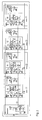
- einen Aufbau eines vier Teilnehmer aufweisenden Bussystems zur Adressvergabe mit diversen optionalen Zusatzmodulen, wobei die zur Bus-Kommunikation erforderlichen Komparatoren nicht dargestellt sind, da sie die Adressvergabe nicht betreffen,
- Fig. 2
- einen Aufbau des gleichen Systems wie in Fig. 1, jedoch bei umgekehrter Polung von VDD1 und VDD2 zur Veranschaulichung des Umstandes, dass die Polung von VDD1 und VDD2 nicht ausschlaggebend ist, wobei beide Varianten durch Spiegelung an der x-Achse ineinander überführbar sind und lediglich ein Teilnehmer dargestellt ist,
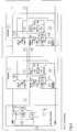
- Fig. 3
- einen Aufbau eines Bussystems zur Adressvergabe bei Nutzung der gleichen Strukturen für Kommunikation und Adressvergabe, wobei lediglich ein Teilnehmer dargestellt ist,
- Fig. 4
- einen Aufbau des gleichen Systems wie in Fig. 3, jedoch bei umgekehrter Polung,
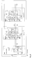
- Fig. 5
- einen Aufbau eines Bussystems zur Adressvergabe mit paralleler Anordnung der Stromdetektoren unter Verwendung einer zusätzlichen Leitung, wobei zwei Teilnehmer dargestellt sind,
- Fig. 6
- ein Bussystem wie in Fig. 5, jedoch bei umgekehrter Polung,
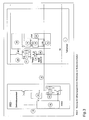
- Fig. 7
- einen Aufbau eines Bussystems zur Adressvergabe unter Ausnutzung einer Versorgungsleitung zur Stromdetektion, und
- Fig. 8
- einen Aufbau des gleichen Systems wie in Fig. 7, jedoch bei umgekehrter Polung.
- Fig. 1
- a structure of a four-subscriber bus system for address assignment with various optional additional modules, the comparators required for bus communication are not shown, since they do not affect the address assignment,
- Fig. 2
- a construction of the same system as in Fig. 1, but with reversed polarity of VDD1 and VDD2 to illustrate the fact that the polarity of VDD1 and VDD2 is not crucial, both variants by mirroring on the x-axis are interconvertible and only a participant is shown
- Fig. 3
- a structure of a bus system for address assignment when using the same structures for communication and address assignment, wherein only one participant is shown,
- Fig. 4
- a structure of the same system as in Fig. 3, but with reverse polarity,
- Fig. 5
- a structure of a bus system for address allocation with parallel arrangement of the current detectors using an additional line, wherein two participants are shown,
- Fig. 6
- a bus system as in FIG. 5, but with reverse polarity,
- Fig. 7
- a structure of a bus system for address allocation using a supply line for current detection, and
- Fig. 8
- a structure of the same system as in Fig. 7, but with reverse polarity.
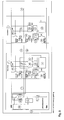
Ganz allgemein gilt für die in den Fign. 1 bis 8 gezeigten Bussystemen, dass
eine Zentralsteuereinheit 14 die Busleitung 12 bei der erfindungsgemäßen
Adressierung der Teilnehmer 1 bis 4 gegen eine Seite der Betriebsspannung
VDD2 legt, während jeder Teilnehmer 1 bis 4 versucht, die Busleitung 12 auf
ein Referenzpotential, üblicherweise die Betriebsspannung VDD1, zu ziehen,
wobei auf Grund des Stromquellenverhaltnes 27 des den Bus auf Betriebsspannung
legenden Schalters 26 durch einen dem Teilnehmer 1 bis 4 zugeordneten
Detektor 22 in der Busleitung 12 ein Strom detektierbar ist. Wenn der
Teilnehmer mit seiner Ansteuereinheit 24 diesen Stromabfall detektiert,
schaltet er seinen Schalter 26 aus. Durch ein zeitlich definiertes langsames
Zuschalten der geschalteten Stromquellen spielt sich dieser Vorgang innerhalb
einer Gruppe von Teilnehmern 1 bis 4 sequenziell ab, bis der letzte Teilnehmer
erreicht ist. Von dem diesem Teilnehmer 4 zugeordneten Detektor 22 wird in
jedem Fall kein Strom detektiert, so dass nach Ablauf einer vorgebbaren Einschaltzeitspanne
der Schalter 26 dieses Teilnehmers 1 bis 4 noch geöffnet ist.
Damit ist einer der Teilnehmer aus der Gruppe sämtlicher Teilnehmer 1 bis 4
spezifiziert, so dass diesem Teilnehmer nunmehr eine Adresse zuteil werden
kann. Während weiterer Adressierzyklen wird nun auf die gleiche Weise mit
den übrigen Teilnehmern verfahren, wobei der Schalter des bereits adressierten
Teilnehmers 4 stets offen bleibt. In general, for the in Figs. 1 to 8 bus systems shown that
a
- 1414
-
Zentralsteuereinheit mit
- 51
- Pullup-Widerstand
- 52
- Komparator für BUS-Betrieb
- 53
- Ansteuerung der physikalischen BUS-Schnittstelle
- 30
- Treiber für BUS-Betrieb: Schalter mit resistivem oder Strom-quellenverhalten
- 51
- Pullup resistor
- 52
- Comparator for BUS operation
- 53
- Control of the physical BUS interface
- 30
- Driver for BUS operation: switch with resistive or current source behavior
- 1 bis 41 to 4
-
Teilnehmer mit
- 50
- für die Buskommunikation notwendiger Schalter
- 22
- Stromdetektoren mit
- 16
- Shunt-Widerstand
- 18
- Komparator
- 20
- Vorverstärker
- 24
- Steuereinheit
- 26
- Schalter eines jeden Teilnehmers zur Einprägung eines Messstroms
- 27
- Widerstands- oder Stromquellenverhalten des Schalters 26
- 28
- Verbindungsleitung, die von der Busleitung 12 abzweigt
- 50
- Switch required for bus communication
- 22
- Current detectors with
- 16
- Shunt resistor
- 18
- comparator
- 20
- preamplifier
- 24
- control unit
- 26
- Switch of each participant to impress a measuring current
- 27
- Resistance or current source behavior of the
switch 26 - 28
- Connecting line, which branches off from the
bus line 12
- 40,4140.41
- schaltbarer BUS-Pullup (optionale Zusatzmodule)Switchable BUS pullup (optional additional modules)
- 31,41,5431,41,54
- Verpolschutzdioden (optionale Zusatzmodule)Reverse polarity protection diodes (optional additional modules)
Claims (41)
wobei bei dem Verfahren
wobei bei diesem Verfahren
wherein in the method
being in this process
wobei bei dem Verfahren
wobei bei diesem Verfahren als Neuerung im Sinne der Erfindung
wherein in the method
wherein in this method as an innovation within the meaning of the invention
wobei bei diesem Verfahren
being in this process
wobei bei diesem Verfahren
being in this process
Priority Applications (3)
| Application Number | Priority Date | Filing Date | Title |
|---|---|---|---|
| DE502004008117T DE502004008117D1 (en) | 2004-06-03 | 2004-06-03 | Method for addressing the subscribers of a bus system |
| EP04013060A EP1603282B1 (en) | 2004-06-03 | 2004-06-03 | Method for addressing subscribers of a bus system |
| AT04013060T ATE409378T1 (en) | 2004-06-03 | 2004-06-03 | METHOD FOR ADDRESSING THE PARTICIPANTS OF A BUS SYSTEM |
Applications Claiming Priority (1)
| Application Number | Priority Date | Filing Date | Title |
|---|---|---|---|
| EP04013060A EP1603282B1 (en) | 2004-06-03 | 2004-06-03 | Method for addressing subscribers of a bus system |
Publications (2)
| Publication Number | Publication Date |
|---|---|
| EP1603282A1 true EP1603282A1 (en) | 2005-12-07 |
| EP1603282B1 EP1603282B1 (en) | 2008-09-24 |
Family
ID=34925226
Family Applications (1)
| Application Number | Title | Priority Date | Filing Date |
|---|---|---|---|
| EP04013060A Expired - Lifetime EP1603282B1 (en) | 2004-06-03 | 2004-06-03 | Method for addressing subscribers of a bus system |
Country Status (3)
| Country | Link |
|---|---|
| EP (1) | EP1603282B1 (en) |
| AT (1) | ATE409378T1 (en) |
| DE (1) | DE502004008117D1 (en) |
Cited By (9)
| Publication number | Priority date | Publication date | Assignee | Title |
|---|---|---|---|---|
| DE102010026431A1 (en) | 2010-07-06 | 2012-01-12 | Jörg Hartzsch | Method for dispatching address of control device e.g. parking sensor to bus system, involves stopping supply of additional power to control devices so that device current increases up to maximum current only |
| EP2438777A1 (en) * | 2009-06-05 | 2012-04-11 | Otis Elevator Company | System and method for automatically addressing devices on a communication network |
| DE102005048548B4 (en) * | 2005-10-11 | 2016-12-01 | Robert Bosch Gmbh | Device for data transmission and bus station for data transmission to a control device |
| EP3209001A1 (en) * | 2016-02-19 | 2017-08-23 | NXP USA, Inc. | Auto-addressing of communication nodes |
| EP3397031A1 (en) | 2017-04-28 | 2018-10-31 | ELMOS Semiconductor Aktiengesellschaft | Method for the automatic determination of the position of a light within a light strip, light strip and light strip system |
| DE102017128923A1 (en) | 2017-09-26 | 2019-03-28 | Elmos Semiconductor Aktiengesellschaft | Bus node for a bus system with favorable EMC behavior and the ability to assign bus node addresses by means of an associated method |
| EP3493481A1 (en) * | 2017-11-30 | 2019-06-05 | ELMOS Semiconductor AG | Method for the supply of addressing streams through bus nodes of a serial data bus system and bus node for such a data bus system |
| US10367782B2 (en) | 2017-12-05 | 2019-07-30 | Elmos Semiconductor Ag | Serial bus auto-addressing |
| GB2575540A (en) * | 2018-05-29 | 2020-01-15 | Continental Powertrain Usa Llc | Automatic location based addressing method for network participants in a serial bus system |
Families Citing this family (3)
| Publication number | Priority date | Publication date | Assignee | Title |
|---|---|---|---|---|
| DE102013212954A1 (en) | 2013-07-03 | 2015-01-08 | Elmos Semiconductor Ag | Method for addressing the subscribers of a bus system |
| EP3703344B1 (en) | 2019-02-27 | 2021-05-12 | Elmos Semiconductor SE | Method for providing the possibility of checking the correctness of addresses previously allocated to bus nodes of a serial data bus system |
| DE102020113332A1 (en) | 2020-05-18 | 2021-11-18 | Elmos Semiconductor Se | Downwardly compatible bus system with low bus resistance with the ability to assign bus node addresses using AMR or GMR measuring equipment |
Citations (3)
| Publication number | Priority date | Publication date | Assignee | Title |
|---|---|---|---|---|
| US5450072A (en) * | 1990-05-10 | 1995-09-12 | Vockenhuber; Peter | Addressing device |
| DE19940700A1 (en) * | 1999-08-27 | 2001-03-08 | Job Lizenz Gmbh & Co Kg | Method and device for the automatic assignment of detector addresses in a hazard detection system |
| DE10147512A1 (en) * | 2001-09-26 | 2003-04-30 | Elmos Semiconductor Ag | Addressing system provides a connection path between multiple user units in a bus system |
-
2004
- 2004-06-03 AT AT04013060T patent/ATE409378T1/en not_active IP Right Cessation
- 2004-06-03 DE DE502004008117T patent/DE502004008117D1/en not_active Expired - Lifetime
- 2004-06-03 EP EP04013060A patent/EP1603282B1/en not_active Expired - Lifetime
Patent Citations (3)
| Publication number | Priority date | Publication date | Assignee | Title |
|---|---|---|---|---|
| US5450072A (en) * | 1990-05-10 | 1995-09-12 | Vockenhuber; Peter | Addressing device |
| DE19940700A1 (en) * | 1999-08-27 | 2001-03-08 | Job Lizenz Gmbh & Co Kg | Method and device for the automatic assignment of detector addresses in a hazard detection system |
| DE10147512A1 (en) * | 2001-09-26 | 2003-04-30 | Elmos Semiconductor Ag | Addressing system provides a connection path between multiple user units in a bus system |
Cited By (16)
| Publication number | Priority date | Publication date | Assignee | Title |
|---|---|---|---|---|
| DE102005048548B4 (en) * | 2005-10-11 | 2016-12-01 | Robert Bosch Gmbh | Device for data transmission and bus station for data transmission to a control device |
| EP2438777A1 (en) * | 2009-06-05 | 2012-04-11 | Otis Elevator Company | System and method for automatically addressing devices on a communication network |
| EP2438777A4 (en) * | 2009-06-05 | 2014-10-08 | Otis Elevator Co | System and method for automatically addressing devices on a communication network |
| DE102010026431A1 (en) | 2010-07-06 | 2012-01-12 | Jörg Hartzsch | Method for dispatching address of control device e.g. parking sensor to bus system, involves stopping supply of additional power to control devices so that device current increases up to maximum current only |
| DE102010026431B4 (en) * | 2010-07-06 | 2012-06-28 | Jörg Hartzsch | Method for allocating addresses to subscribers of a bus system |
| EP3209001A1 (en) * | 2016-02-19 | 2017-08-23 | NXP USA, Inc. | Auto-addressing of communication nodes |
| CN107104702A (en) * | 2016-02-19 | 2017-08-29 | 恩智浦有限公司 | A kind of communication system and device |
| US10013379B2 (en) | 2016-02-19 | 2018-07-03 | Nxp B.V. | Auto-addressing of communication nodes |
| EP3397031A1 (en) | 2017-04-28 | 2018-10-31 | ELMOS Semiconductor Aktiengesellschaft | Method for the automatic determination of the position of a light within a light strip, light strip and light strip system |
| DE102017128923A1 (en) | 2017-09-26 | 2019-03-28 | Elmos Semiconductor Aktiengesellschaft | Bus node for a bus system with favorable EMC behavior and the ability to assign bus node addresses by means of an associated method |
| EP3493481A1 (en) * | 2017-11-30 | 2019-06-05 | ELMOS Semiconductor AG | Method for the supply of addressing streams through bus nodes of a serial data bus system and bus node for such a data bus system |
| EP3493479A1 (en) * | 2017-11-30 | 2019-06-05 | Elmos Semiconductor Aktiengesellschaft | Method for the supply of addressing streams through bus nodes of a serial data bus system and bus node for such a data bus system |
| US10361996B2 (en) | 2017-11-30 | 2019-07-23 | Elmos Semiconductor Ag | Serial bus auto-addressing |
| US10367782B2 (en) | 2017-12-05 | 2019-07-30 | Elmos Semiconductor Ag | Serial bus auto-addressing |
| GB2575540A (en) * | 2018-05-29 | 2020-01-15 | Continental Powertrain Usa Llc | Automatic location based addressing method for network participants in a serial bus system |
| US10956352B2 (en) | 2018-05-29 | 2021-03-23 | Continental Automotive Systems, Inc. | Automatic location based addressing method for network participants in a serial bus system |
Also Published As
| Publication number | Publication date |
|---|---|
| ATE409378T1 (en) | 2008-10-15 |
| EP1603282B1 (en) | 2008-09-24 |
| DE502004008117D1 (en) | 2008-11-06 |
Similar Documents
| Publication | Publication Date | Title |
|---|---|---|
| EP1490772B1 (en) | Method for addressing the users of a bus system by means of identification flows | |
| DE10147512B4 (en) | Method for addressing the participants in a bus system | |
| DE10256631B4 (en) | Verfarhen for addressing the participants of a bus system | |
| EP2720051B1 (en) | Safety system | |
| DE102006048073A1 (en) | Device for sensing a fault current in a fieldbus system | |
| WO1990009713A1 (en) | Network interface | |
| DE102010026431A1 (en) | Method for dispatching address of control device e.g. parking sensor to bus system, involves stopping supply of additional power to control devices so that device current increases up to maximum current only | |
| EP1603282A1 (en) | Method for addressing subscribers of a bus system | |
| DE102011087152B4 (en) | Test system and test method for wiring harnesses | |
| EP2007077A1 (en) | Method of detecting the position of slave devices in a series connection and slave device for a series connection | |
| EP1917651B1 (en) | Facility management system or danger warning system | |
| EP1298851B1 (en) | Method of addressing nodes of a bus system | |
| DE4328932C2 (en) | Method and device for remote polling of measuring points | |
| DE19906932B4 (en) | Binary | |
| DE102022126893A1 (en) | Methods and interconnection for operating a network or network section | |
| DE102018126787A1 (en) | Charging station for electric vehicles with at least two charging connections and an optionally switchable power electronics unit | |
| DE102009050692B4 (en) | Security communication system for signaling system states | |
| DE102009023262A1 (en) | Circuit for monitoring limit switches of a 4-wire three-phase drive of a switch | |
| DE19813964A1 (en) | Ring bus system with a central unit and a number or control modules, in particular for motor vehicle passenger protection systems | |
| EP1457399B1 (en) | Initialization method for a data bus | |
| DE19813952C1 (en) | Signaling output stage for generating digital voltage signals on a bus system | |
| DE102017116385B3 (en) | fieldbus system | |
| DE19850869A1 (en) | Line coupling and use of a line coupling in a bus system | |
| DE102017114662B3 (en) | FIELD BUS SYSTEM | |
| DE2828551C2 (en) | Circuit arrangement for querying contacts combined in a matrix |
Legal Events
| Date | Code | Title | Description |
|---|---|---|---|
| PUAI | Public reference made under article 153(3) epc to a published international application that has entered the european phase |
Free format text: ORIGINAL CODE: 0009012 |
|
| AK | Designated contracting states |
Kind code of ref document: A1 Designated state(s): AT BE BG CH CY CZ DE DK EE ES FI FR GB GR HU IE IT LI LU MC NL PL PT RO SE SI SK TR |
|
| AX | Request for extension of the european patent |
Extension state: AL HR LT LV MK |
|
| 17P | Request for examination filed |
Effective date: 20060601 |
|
| AKX | Designation fees paid |
Designated state(s): AT BE BG CH CY CZ DE DK EE ES FI FR GB GR HU IE IT LI LU MC NL PL PT RO SE SI SK TR |
|
| 17Q | First examination report despatched |
Effective date: 20060720 |
|
| GRAP | Despatch of communication of intention to grant a patent |
Free format text: ORIGINAL CODE: EPIDOSNIGR1 |
|
| GRAS | Grant fee paid |
Free format text: ORIGINAL CODE: EPIDOSNIGR3 |
|
| GRAA | (expected) grant |
Free format text: ORIGINAL CODE: 0009210 |
|
| AK | Designated contracting states |
Kind code of ref document: B1 Designated state(s): AT BE BG CH CY CZ DE DK EE ES FI FR GB GR HU IE IT LI LU MC NL PL PT RO SE SI SK TR |
|
| REG | Reference to a national code |
Ref country code: GB Ref legal event code: FG4D Free format text: NOT ENGLISH |
|
| REG | Reference to a national code |
Ref country code: CH Ref legal event code: EP |
|
| REG | Reference to a national code |
Ref country code: CH Ref legal event code: NV Representative=s name: HEPP WENGER RYFFEL AG |
|
| REG | Reference to a national code |
Ref country code: IE Ref legal event code: FG4D Free format text: LANGUAGE OF EP DOCUMENT: GERMAN |
|
| REF | Corresponds to: |
Ref document number: 502004008117 Country of ref document: DE Date of ref document: 20081106 Kind code of ref document: P |
|
| PG25 | Lapsed in a contracting state [announced via postgrant information from national office to epo] |
Ref country code: FI Free format text: LAPSE BECAUSE OF FAILURE TO SUBMIT A TRANSLATION OF THE DESCRIPTION OR TO PAY THE FEE WITHIN THE PRESCRIBED TIME-LIMIT Effective date: 20080924 Ref country code: SI Free format text: LAPSE BECAUSE OF FAILURE TO SUBMIT A TRANSLATION OF THE DESCRIPTION OR TO PAY THE FEE WITHIN THE PRESCRIBED TIME-LIMIT Effective date: 20080924 |
|
| PG25 | Lapsed in a contracting state [announced via postgrant information from national office to epo] |
Ref country code: BG Free format text: LAPSE BECAUSE OF FAILURE TO SUBMIT A TRANSLATION OF THE DESCRIPTION OR TO PAY THE FEE WITHIN THE PRESCRIBED TIME-LIMIT Effective date: 20081224 Ref country code: ES Free format text: LAPSE BECAUSE OF FAILURE TO SUBMIT A TRANSLATION OF THE DESCRIPTION OR TO PAY THE FEE WITHIN THE PRESCRIBED TIME-LIMIT Effective date: 20090104 |
|
| PG25 | Lapsed in a contracting state [announced via postgrant information from national office to epo] |
Ref country code: PT Free format text: LAPSE BECAUSE OF FAILURE TO SUBMIT A TRANSLATION OF THE DESCRIPTION OR TO PAY THE FEE WITHIN THE PRESCRIBED TIME-LIMIT Effective date: 20090224 Ref country code: CZ Free format text: LAPSE BECAUSE OF FAILURE TO SUBMIT A TRANSLATION OF THE DESCRIPTION OR TO PAY THE FEE WITHIN THE PRESCRIBED TIME-LIMIT Effective date: 20080924 Ref country code: RO Free format text: LAPSE BECAUSE OF FAILURE TO SUBMIT A TRANSLATION OF THE DESCRIPTION OR TO PAY THE FEE WITHIN THE PRESCRIBED TIME-LIMIT Effective date: 20080924 Ref country code: SK Free format text: LAPSE BECAUSE OF FAILURE TO SUBMIT A TRANSLATION OF THE DESCRIPTION OR TO PAY THE FEE WITHIN THE PRESCRIBED TIME-LIMIT Effective date: 20080924 |
|
| PG25 | Lapsed in a contracting state [announced via postgrant information from national office to epo] |
Ref country code: EE Free format text: LAPSE BECAUSE OF FAILURE TO SUBMIT A TRANSLATION OF THE DESCRIPTION OR TO PAY THE FEE WITHIN THE PRESCRIBED TIME-LIMIT Effective date: 20080924 Ref country code: DK Free format text: LAPSE BECAUSE OF FAILURE TO SUBMIT A TRANSLATION OF THE DESCRIPTION OR TO PAY THE FEE WITHIN THE PRESCRIBED TIME-LIMIT Effective date: 20080924 |
|
| PGFP | Annual fee paid to national office [announced via postgrant information from national office to epo] |
Ref country code: IE Payment date: 20090618 Year of fee payment: 6 Ref country code: NL Payment date: 20090624 Year of fee payment: 6 |
|
| PLBE | No opposition filed within time limit |
Free format text: ORIGINAL CODE: 0009261 |
|
| STAA | Information on the status of an ep patent application or granted ep patent |
Free format text: STATUS: NO OPPOSITION FILED WITHIN TIME LIMIT |
|
| PGFP | Annual fee paid to national office [announced via postgrant information from national office to epo] |
Ref country code: AT Payment date: 20090622 Year of fee payment: 6 |
|
| 26N | No opposition filed |
Effective date: 20090625 |
|
| PGFP | Annual fee paid to national office [announced via postgrant information from national office to epo] |
Ref country code: BE Payment date: 20090623 Year of fee payment: 6 |
|
| PGFP | Annual fee paid to national office [announced via postgrant information from national office to epo] |
Ref country code: CH Payment date: 20090624 Year of fee payment: 6 |
|
| PG25 | Lapsed in a contracting state [announced via postgrant information from national office to epo] |
Ref country code: MC Free format text: LAPSE BECAUSE OF NON-PAYMENT OF DUE FEES Effective date: 20090630 Ref country code: SE Free format text: LAPSE BECAUSE OF FAILURE TO SUBMIT A TRANSLATION OF THE DESCRIPTION OR TO PAY THE FEE WITHIN THE PRESCRIBED TIME-LIMIT Effective date: 20081224 |
|
| PG25 | Lapsed in a contracting state [announced via postgrant information from national office to epo] |
Ref country code: PL Free format text: LAPSE BECAUSE OF FAILURE TO SUBMIT A TRANSLATION OF THE DESCRIPTION OR TO PAY THE FEE WITHIN THE PRESCRIBED TIME-LIMIT Effective date: 20080924 |
|
| PG25 | Lapsed in a contracting state [announced via postgrant information from national office to epo] |
Ref country code: GR Free format text: LAPSE BECAUSE OF FAILURE TO SUBMIT A TRANSLATION OF THE DESCRIPTION OR TO PAY THE FEE WITHIN THE PRESCRIBED TIME-LIMIT Effective date: 20081225 |
|
| BERE | Be: lapsed |
Owner name: ELMOS SEMICONDUCTOR A.G. Effective date: 20100630 |
|
| REG | Reference to a national code |
Ref country code: NL Ref legal event code: V1 Effective date: 20110101 |
|
| REG | Reference to a national code |
Ref country code: CH Ref legal event code: PL |
|
| PG25 | Lapsed in a contracting state [announced via postgrant information from national office to epo] |
Ref country code: LU Free format text: LAPSE BECAUSE OF NON-PAYMENT OF DUE FEES Effective date: 20090603 Ref country code: LI Free format text: LAPSE BECAUSE OF NON-PAYMENT OF DUE FEES Effective date: 20100630 Ref country code: CH Free format text: LAPSE BECAUSE OF NON-PAYMENT OF DUE FEES Effective date: 20100630 Ref country code: IE Free format text: LAPSE BECAUSE OF NON-PAYMENT OF DUE FEES Effective date: 20100603 |
|
| PG25 | Lapsed in a contracting state [announced via postgrant information from national office to epo] |
Ref country code: NL Free format text: LAPSE BECAUSE OF NON-PAYMENT OF DUE FEES Effective date: 20110101 Ref country code: AT Free format text: LAPSE BECAUSE OF NON-PAYMENT OF DUE FEES Effective date: 20100603 |
|
| PG25 | Lapsed in a contracting state [announced via postgrant information from national office to epo] |
Ref country code: BE Free format text: LAPSE BECAUSE OF NON-PAYMENT OF DUE FEES Effective date: 20100630 Ref country code: HU Free format text: LAPSE BECAUSE OF FAILURE TO SUBMIT A TRANSLATION OF THE DESCRIPTION OR TO PAY THE FEE WITHIN THE PRESCRIBED TIME-LIMIT Effective date: 20090325 |
|
| PG25 | Lapsed in a contracting state [announced via postgrant information from national office to epo] |
Ref country code: TR Free format text: LAPSE BECAUSE OF FAILURE TO SUBMIT A TRANSLATION OF THE DESCRIPTION OR TO PAY THE FEE WITHIN THE PRESCRIBED TIME-LIMIT Effective date: 20080924 |
|
| PG25 | Lapsed in a contracting state [announced via postgrant information from national office to epo] |
Ref country code: CY Free format text: LAPSE BECAUSE OF FAILURE TO SUBMIT A TRANSLATION OF THE DESCRIPTION OR TO PAY THE FEE WITHIN THE PRESCRIBED TIME-LIMIT Effective date: 20080924 |
|
| REG | Reference to a national code |
Ref country code: DE Ref legal event code: R082 Ref document number: 502004008117 Country of ref document: DE Representative=s name: VON KREISLER SELTING WERNER - PARTNERSCHAFT VO, DE |
|
| REG | Reference to a national code |
Ref country code: DE Ref legal event code: R082 Ref document number: 502004008117 Country of ref document: DE Representative=s name: VON KREISLER SELTING WERNER - PARTNERSCHAFT VO, DE Effective date: 20150108 Ref country code: DE Ref legal event code: R081 Ref document number: 502004008117 Country of ref document: DE Owner name: ELMOS SEMICONDUCTOR AKTIENGESELLSCHAFT, DE Free format text: FORMER OWNER: ELMOS SEMICONDUCTOR AG, 44227 DORTMUND, DE Effective date: 20150108 Ref country code: DE Ref legal event code: R082 Ref document number: 502004008117 Country of ref document: DE Representative=s name: DOMPATENT VON KREISLER SELTING WERNER - PARTNE, DE Effective date: 20150108 |
|
| REG | Reference to a national code |
Ref country code: FR Ref legal event code: PLFP Year of fee payment: 13 |
|
| REG | Reference to a national code |
Ref country code: FR Ref legal event code: PLFP Year of fee payment: 14 |
|
| REG | Reference to a national code |
Ref country code: FR Ref legal event code: PLFP Year of fee payment: 15 |
|
| REG | Reference to a national code |
Ref country code: DE Ref legal event code: R082 Ref document number: 502004008117 Country of ref document: DE Representative=s name: DOMPATENT VON KREISLER SELTING WERNER - PARTNE, DE Ref country code: DE Ref legal event code: R081 Ref document number: 502004008117 Country of ref document: DE Owner name: ELMOS SEMICONDUCTOR SE, DE Free format text: FORMER OWNER: ELMOS SEMICONDUCTOR AKTIENGESELLSCHAFT, 44227 DORTMUND, DE |
|
| PGFP | Annual fee paid to national office [announced via postgrant information from national office to epo] |
Ref country code: FR Payment date: 20230622 Year of fee payment: 20 Ref country code: DE Payment date: 20230620 Year of fee payment: 20 |
|
| P02 | Opt-out of the competence of the unified patent court (upc) changed |
Effective date: 20230728 |
|
| PGFP | Annual fee paid to national office [announced via postgrant information from national office to epo] |
Ref country code: IT Payment date: 20230630 Year of fee payment: 20 Ref country code: GB Payment date: 20230622 Year of fee payment: 20 |
|
| REG | Reference to a national code |
Ref country code: DE Ref legal event code: R071 Ref document number: 502004008117 Country of ref document: DE |
|
| REG | Reference to a national code |
Ref country code: GB Ref legal event code: PE20 Expiry date: 20240602 |
|
| PG25 | Lapsed in a contracting state [announced via postgrant information from national office to epo] |
Ref country code: GB Free format text: LAPSE BECAUSE OF EXPIRATION OF PROTECTION Effective date: 20240602 |
|
| PG25 | Lapsed in a contracting state [announced via postgrant information from national office to epo] |
Ref country code: GB Free format text: LAPSE BECAUSE OF EXPIRATION OF PROTECTION Effective date: 20240602 |