DE102012217618A1 - Method for recasting contour flat conductor used in e.g. vehicle, involves inserting and positioning flat conductor in casting tool using spacers to ensure recasting of flat conductor, and recasting flat conductor partly - Google Patents
Method for recasting contour flat conductor used in e.g. vehicle, involves inserting and positioning flat conductor in casting tool using spacers to ensure recasting of flat conductor, and recasting flat conductor partly Download PDFInfo
- Publication number
- DE102012217618A1 DE102012217618A1 DE201210217618 DE102012217618A DE102012217618A1 DE 102012217618 A1 DE102012217618 A1 DE 102012217618A1 DE 201210217618 DE201210217618 DE 201210217618 DE 102012217618 A DE102012217618 A DE 102012217618A DE 102012217618 A1 DE102012217618 A1 DE 102012217618A1
- Authority
- DE
- Germany
- Prior art keywords
- flat conductor
- casting
- conductor
- electrically conductive
- conductive layers
- Prior art date
- Legal status (The legal status is an assumption and is not a legal conclusion. Google has not performed a legal analysis and makes no representation as to the accuracy of the status listed.)
- Pending
Links
Images


Classifications
-
- B—PERFORMING OPERATIONS; TRANSPORTING
- B29—WORKING OF PLASTICS; WORKING OF SUBSTANCES IN A PLASTIC STATE IN GENERAL
- B29C—SHAPING OR JOINING OF PLASTICS; SHAPING OF MATERIAL IN A PLASTIC STATE, NOT OTHERWISE PROVIDED FOR; AFTER-TREATMENT OF THE SHAPED PRODUCTS, e.g. REPAIRING
- B29C39/00—Shaping by casting, i.e. introducing the moulding material into a mould or between confining surfaces without significant moulding pressure; Apparatus therefor
- B29C39/02—Shaping by casting, i.e. introducing the moulding material into a mould or between confining surfaces without significant moulding pressure; Apparatus therefor for making articles of definite length, i.e. discrete articles
- B29C39/10—Shaping by casting, i.e. introducing the moulding material into a mould or between confining surfaces without significant moulding pressure; Apparatus therefor for making articles of definite length, i.e. discrete articles incorporating preformed parts or layers, e.g. casting around inserts or for coating articles
-
- B—PERFORMING OPERATIONS; TRANSPORTING
- B29—WORKING OF PLASTICS; WORKING OF SUBSTANCES IN A PLASTIC STATE IN GENERAL
- B29C—SHAPING OR JOINING OF PLASTICS; SHAPING OF MATERIAL IN A PLASTIC STATE, NOT OTHERWISE PROVIDED FOR; AFTER-TREATMENT OF THE SHAPED PRODUCTS, e.g. REPAIRING
- B29C33/00—Moulds or cores; Details thereof or accessories therefor
- B29C33/12—Moulds or cores; Details thereof or accessories therefor with incorporated means for positioning inserts, e.g. labels
-
- B—PERFORMING OPERATIONS; TRANSPORTING
- B29—WORKING OF PLASTICS; WORKING OF SUBSTANCES IN A PLASTIC STATE IN GENERAL
- B29C—SHAPING OR JOINING OF PLASTICS; SHAPING OF MATERIAL IN A PLASTIC STATE, NOT OTHERWISE PROVIDED FOR; AFTER-TREATMENT OF THE SHAPED PRODUCTS, e.g. REPAIRING
- B29C39/00—Shaping by casting, i.e. introducing the moulding material into a mould or between confining surfaces without significant moulding pressure; Apparatus therefor
- B29C39/22—Component parts, details or accessories; Auxiliary operations
- B29C39/26—Moulds or cores
-
- H—ELECTRICITY
- H01—ELECTRIC ELEMENTS
- H01B—CABLES; CONDUCTORS; INSULATORS; SELECTION OF MATERIALS FOR THEIR CONDUCTIVE, INSULATING OR DIELECTRIC PROPERTIES
- H01B13/00—Apparatus or processes specially adapted for manufacturing conductors or cables
- H01B13/012—Apparatus or processes specially adapted for manufacturing conductors or cables for manufacturing wire harnesses
- H01B13/01254—Flat-harness manufacturing
Abstract
Description
TECHNISCHES GEBIETTECHNICAL AREA
Die Erfindung betrifft ein Verfahren zum Umgießen eines konturgeformten Flachleiters. Dabei kommt die vorliegende Erfindung insbesondere für mehrschichtige Flachleiter im Automobilbereich in Frage, wobei der Flachleiter zur Energieversorgung (Niedervolt- oder Hochvoltanwendungen) und/oder zur Signalübertragung und/oder zur Erdung dienen kann.The invention relates to a method for encapsulating a contour-shaped flat conductor. In this case, the present invention is particularly suitable for multilayer flat conductors in the automotive sector, wherein the flat conductor can be used for power supply (low-voltage or high-voltage applications) and / or for signal transmission and / or grounding.
HINTERGRUND DER ERFINDUNGBACKGROUND OF THE INVENTION
Bisher werden im Automobilbereich Kabelbäume in Form von Rundleitern mit zum Teil starken Durchmessern verwendet. Diese dienen neben der Energieversorgung auch zur Erdung im Kfz.So far, in the automotive sector harnesses in the form of round conductors are sometimes used with strong diameters. These serve in addition to the power supply for grounding in the vehicle.
In den letzten Jahren kommen jedoch vermehrt Flachleiter, insbesondere aus Aluminium zum Einsatz. Dadurch können der Einbauraum und das Leitergewicht reduziert werden. Weiterhin hat die geometrische Form der Flachleiter elektrotechnische Vorteile gegenüber Rundleitern. Durch einen mehrschichtigen Flachleiter kann neben der Energie- und Signalversorgung auch die Masserückführung unabhängig von den Karosseriewerkstoffen im Kfz erfolgen. Durch den geschichteten, flachen Aufbau werden zusätzlich die elektromagnetischen Felder außerhalb des Flachleiters eliminiert.In recent years, however, increasingly flat conductor, in particular made of aluminum are used. As a result, the installation space and the conductor weight can be reduced. Furthermore, the geometric shape of the flat conductor has electrical advantages over round conductors. Through a multi-layer flat conductor can be carried out in addition to the power and signal supply and the Masserückführung regardless of the body materials in the vehicle. Due to the layered, flat construction, the electromagnetic fields outside the flat conductor are additionally eliminated.
Der Flachleiter wird beispielsweise entlang der Bodengruppenkontur vom Hinterraum bis zum Motorraum verlegt.The flat conductor is laid, for example, along the floor group contour from the back room to the engine compartment.
Der in Kontur geformte Mehrschichtleiter mit seitlich und/oder stirnseitig angebrachten Kontaktierungsbereichen muss nach außen hin isoliert werden. Neben einer elektrischen Isolation werden eine hohe Wasserdichtigkeit (Längswasserdichtigkeit) und ein hoher Abrasionsschutz gefordert.The molded in contour multi-layer conductor with laterally and / or frontally mounted contacting areas must be isolated to the outside. In addition to electrical insulation, high water resistance (longitudinal water-tightness) and high abrasion protection are required.
ZUSAMMENFASSUNG DER ERFINDUNGSUMMARY OF THE INVENTION
Eine Aufgabe der Erfindung besteht darin, ein Verfahren zum Umgießen eines konturgeformten Flachleiters anzugeben, mit dem auf einfache Weise trotz Konturformung des Flachleiters eine reproduzierbare Gießwandstärke entlang des Leiters realisiert werden kann. Eine Aufgabe besteht ferner darin, einen entsprechenden Flachleiter und eine entsprechende Gießform anzugeben.An object of the invention is to provide a method for casting over a contour-shaped flat conductor, with which a reproducible casting wall thickness along the conductor can be realized in a simple manner despite contouring of the flat conductor. A further object is to specify a corresponding flat conductor and a corresponding casting mold.
Diese Aufgabe wird mit einem Verfahren mit den Merkmalen des Anspruchs 1, einem Flachleiter gemäß Anspruch 19 und einem Gießwerkzeug gemäß Anspruch 20 gelöst. Vorteilhafte Weiterbildungen finden sich in den Unteransprüchen.This object is achieved by a method having the features of
Beim erfindungsgemäßen Verfahren wird zunächst ein konturgeformter Flachleiter mit einer oder mit mehreren elektrisch leitenden Schichten bereitgestellt. Der Flachleiter ist vorzugsweise ein mehrschichtiger Flachleiter, der bereits zu einer Kontur umgeformt ist. Das bedeutet, dass der Flachleiter zweidimensional oder dreidimensional entlang der Erstreckungsrichtung umgeformt ist, sodass dieser bevorzugt an eine Kontur im Automobil, beispielsweise an die Kontur einer Bodenwanne angepasst ist. Das Umgießen eines solchen Flachleiters stellt aufgrund der Umformungsradien eine Herausforderung dar. Im Falle mehrerer leitender Schichten, die sandwichartig gestapelt sind, sind zwischen diesen einzelnen leitenden Schichten isolierende Schichten vorgesehen. Insbesondere kann der Flachleiter aus mehreren stromleitenden und einer gleichen Anzahl masseleitenden Schichten mit zwischenliegenden Isolationsschichten ausgebildet sein. Auch auf den jeweiligen außenliegenden Flächen können Isolationsschichten als Abschluss vorgesehen sein. Beispielsweise kann es sich bei den elektrisch leitenden Schichten um Schichten aus Aluminium oder einer Aluminiumlegierung oder Messing handeln. Aufgrund der Gewichtseinsparung sollten die elektrisch leitenden Schichten aus z. B. Aluminium mit einer Schichtstärke zwischen 0,3 mm und 5 mm ausgeführt sein. Der Flachleiter kann im Kfz zur Energieversorgung (Niedervolt- oder Hochvoltanwendungen) und/oder zur Signalübertragung und/oder zu Masserückführung dienen. Typische Abmessungen bei 12 V bzw. 48 V (Niedervoltanwendung) für die elektrisch leitenden Schichten aus Aluminium sind 1 mm × 60 mm im Querschnitt. Für eine hohe elektrische Leitfähigkeit sind beim Aluminium Reinheitsgrade von mindestens 99,5% bevorzugt, noch bevorzugter Reinheitsgrade zwischen 99,5% und 99,7%. Bei Kupfer ist beispielsweise das Kupfermaterial E-Cu 58 mit einer Zugfestigkeit von 220 bis 300 MPa zu empfehlen.In the method according to the invention, first a contour-shaped flat conductor with one or more electrically conductive layers is provided. The flat conductor is preferably a multilayer flat conductor that has already been formed into a contour. This means that the flat conductor is formed two-dimensionally or three-dimensionally along the extension direction, so that it is preferably adapted to a contour in the automobile, for example to the contour of a floor pan. Circulation of such a flat conductor poses a challenge due to the radii of transformation. In the case of multiple conductive layers sandwiched, insulating layers are provided between these individual conductive layers. In particular, the flat conductor may be formed of a plurality of current-conducting and an equal number of ground-conducting layers with intermediate insulation layers. Also on the respective outer surfaces insulation layers may be provided as a conclusion. For example, the electrically conductive layers may be layers of aluminum or an aluminum alloy or brass. Due to the weight saving, the electrically conductive layers of z. B. aluminum be designed with a layer thickness between 0.3 mm and 5 mm. The flat conductor can be used in the vehicle for energy supply (low-voltage or high-voltage applications) and / or for signal transmission and / or mass recirculation. Typical dimensions at 12 V or 48 V (low voltage application) for the electrically conductive layers of aluminum are 1 mm × 60 mm in cross section. For high electrical conductivity, purities of at least 99.5% are preferred in aluminum, more preferably purities of between 99.5% and 99.7%. For copper, for example, the copper material E-Cu 58 with a tensile strength of 220 to 300 MPa is recommended.
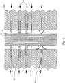
In einem zweiten Schritt wird der Flachleiter in ein Gießwerkzeug eingelegt, wobei ein oder mehrere Abstandsmittel verwendet werden, welche den Abstand des Flachleiters zu den Kavitätswänden des Gießwerkzeugs festlegen. Die Abstandsmittel stellen somit beim Umgießen des Flachleiters eine Mindestwandstärke der durch das Umgießen herzustellenden Ummantelung dar. Die Abstandsmittel sollen kompatibel zum Gießwerkzeug und zum Flachleiterband sein. Vorzugsweise bestehen die Abstandsmittel aus der gleichen Werkstoffgruppe oder dem identischen Material. Die Abstandsmittel können im Werkzeug integriert sein.In a second step, the flat conductor is inserted into a casting tool, wherein one or more spacing means are used, which define the distance of the flat conductor to the cavity walls of the casting tool. The spacing means thus represent a minimum wall thickness of the sheathing to be produced by encapsulation during the casting of the flat conductor. The spacing means should be compatible with the casting tool and with the flat conductor strip. Preferably, the spacing means consist of the same material group or the identical material. The spacing means can be integrated in the tool.
Das Gießmaterial ist elektrisch isolierend und vorzugsweise ein Kunststoff. Durch die geforderten Dauergebrauchstemperaturen von maximal 120°C sind insbesondere duroplastische, d. h. vernetzende Gießsysteme zu bevorzugen. Eine chemische Anbindung des Gießsystems an den Flachleiter möglichst ohne Lufteinschlüsse ist hierbei anzustreben. Besonders geeignete Materialien zum Umgießen des Flachleiters sind thermoplastische Elastomere, wie z. B. Polyurethan, Silikon, Gummi, TPU oder PVC. Anschließend wird der Flachleiter mit dem Gießmaterial umgossen, wodurch der Flachleiter eine Ummantelung erhält. Unter der Bezeichnung „Umgießen” ist insbesondere auch ein teilweises Umgießen des Flachleiters, ein Anspritzen oder Ansprühen des Materials zur Herstellung der Ummantelung mitumfasst.The casting material is electrically insulating and preferably a plastic. Due to the required continuous service temperatures of a maximum of 120 ° C in particular thermosetting, ie cross-linking casting systems are preferable. A chemical connection of the casting system to the flat conductor if possible without air pockets is to strive for this. Particularly suitable materials for encapsulating the flat conductor are thermoplastic elastomers, such as. As polyurethane, silicone, rubber, TPU or PVC. Subsequently, the flat conductor is encapsulated with the casting material, whereby the flat conductor receives a sheath. The term "casting" in particular includes a partial encapsulation of the flat conductor, a sprinkling or spraying of the material for the production of the sheath.
Das beschriebene Umgießen des bereits konturgeformten Flachleiters ist aufgrund der erforderlichen Wasserdichtigkeit, der elektrischen Isolationswerte und einer geforderten hohen Abriebfestigkeit technologisch eine ausgezeichnete Variante zur Herstellung einer Außenabisolierung. Insbesondere für die üblicherweise sehr hohe Funktionsgewährleistung über die komplette Fahrzeuglebensdauer hinaus ist die Gießvariante eine ausgezeichnete Lösung. Darüber hinaus kann mittels Gießen eine definierte Außenkontur realisiert werden, da je nach Gestaltung des Gießwerkzeugs eine Ummantelung mit einer gewünschten Querschnittsdicke bzw. Wanddicke erzielt werden kann.The described encapsulation of the already contoured flat conductor is due to the required water resistance, the electrical insulation values and a required high abrasion resistance technologically an excellent variant for producing a Außenabisolierung. In particular, for the usually very high functional warranty over the entire vehicle life, the casting variant is an excellent solution. In addition, by casting a defined outer contour can be realized, since depending on the design of the casting tool, a jacket with a desired cross-sectional thickness or wall thickness can be achieved.
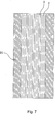
Der konturgeformte Flachleiter besteht vorzugsweise aus vier geschichteten Flachleitern mit den Abmaßen je 1 mm Höhe, 60 mm Breite und einer Bauteillänge von ca. 3000 mm. Die abgewickelte Flachleiterlänge beträgt in diesem Fall vorzugsweise etwa 4500 mm. Die zu erzeugende Gießwandstärke, d. h. die Wandstärke der Ummantelung beträgt vorzugsweise etwa 2 mm.The contour-shaped flat conductor preferably consists of four layered flat conductors with dimensions of 1 mm height, 60 mm width and a component length of about 3000 mm. The developed flat conductor length in this case is preferably about 4500 mm. The casting wall thickness to be produced, d. H. the wall thickness of the casing is preferably about 2 mm.
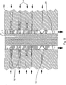
Vorzugsweise ist zumindest eines der verwendeten Abstandsmittel im Gießwerkzeug ein flexibler Abstandshalter mit veränderlichem Abstandsmaß. Diese sind vorzugsweise im Gießwerkzeug fest eingebaut oder mit diesem integriert. Durch eine flexible Beschaffenheit eines oder mehrerer Abstandmittel können sich diese der Kontur des Flachleiterbandes anpassen und gewährleisten damit eine gleichmäßige Ummantelung trotz Kontur des Flachleiters.Preferably, at least one of the spacing means used in the casting tool is a flexible spacer with a variable pitch. These are preferably permanently installed in the casting tool or integrated with it. By a flexible nature of one or more spacer means, these can adapt to the contour of the flat conductor strip and thus ensure a uniform sheath despite the contour of the flat conductor.
Vorzugsweise ist der mindestens eine flexible Abstandshalter pneumatisch oder hydraulisch verfahrbar, wodurch das Gießwerkzeug noch flexibler an die Kontur der Flachleiters anpassbar ist. Darüber hinaus können verfahrbare, aufpumpbare oder anderweitig verstellbare Abstandsmittel beim Einlegen des Mehrschichtleiters ausgefahren werden, wobei diese im Gießprozess während oder nach der kompletten Befüllung zurückgefahren werden, sodass der Mehrschichtleiter im Gießbett fixiert bleibt und die durch die Abstandsmittel entstandenen Freiräume durch Nachdruck oder durch Ausschäumen aufgefüllt werden können. Vorzugsweise sind die Abstandsmittel in gegenüberliegender Anordnung und hierbei vorzugsweise symmetrisch zueinander angeordnet, um ein gleichmäßiges Halten und Umgießen des Flachleiters zu unterstützen. Neben pneumatisch oder hydraulisch verfahrbaren Abstandshaltern ist gemäß einer besonders bevorzugten Ausführungsform mindestens ein Abstandshalter ein aufblasbarer Abstandsbalk. Dieser kann beispielsweise mit einer flexiblen und/oder dehnbaren Außenhaut vorgesehen sein, wodurch sich der Abstandsbalk mittels eines Fluids in eine ausgefahrene Position aufblasen lässt und durch ablasen des Fluides oder durch Erzeugung eines Unterdrucks zurückfahren lässt. Ein solcher Abstandsbalk zeichnet sich durch eine einfache Konstruktion bei sehr hoher Adaptivität aus. Alternativ zu einem mittels Überdruck und/oder Unterdruck beaufschlagbaren Abstandsbalk kann der Abstandsbalk passiv bewegbar ausgeführt sein. Dies kann beispielsweise durch das Gießmaterial durchgeführt werden, indem das Gießmaterial den Abstandsbalk wegdrückt. Dazu werden insbesondere hochviskose Materialien als Gießmaterial bevorzugt. Darüber hinaus kann es sich um ein expansives Material, beispielsweise einem Schaum, handeln. Somit kann sichergestellt werden, dass durch den Masse- und/oder Expansionsdruck des Gießmaterials der Abstandsbalk zurückgedrängt wird, wodurch ein aktives zurückziehen des Abstandsbalks nicht mehr notwendig ist.Preferably, the at least one flexible spacer is pneumatically or hydraulically movable, whereby the casting tool is even more flexible adaptable to the contour of the flat conductor. In addition, movable, inflatable or otherwise adjustable spacers can be extended when inserting the multi-layer conductor, which are moved back in the casting process during or after the complete filling, so that the multi-layer conductor remains fixed in the casting and filled up by the spacer means free spaces by reprinting or by foaming can be. Preferably, the spacing means are arranged in opposite arrangement and in this case preferably symmetrically to one another, in order to support a uniform holding and encapsulation of the flat conductor. In addition to pneumatically or hydraulically movable spacers at least one spacer is an inflatable Abstandsbalk according to a particularly preferred embodiment. This can be provided for example with a flexible and / or stretchable outer skin, whereby the spacer bar can be inflated by means of a fluid in an extended position and can be driven back by ablasen the fluid or by generating a negative pressure. Such a spacer bar is characterized by a simple construction with very high adaptability. As an alternative to a spacer bar which can be acted upon by means of overpressure and / or underpressure, the spacer bar can be designed to be passively movable. This can be done, for example, by the casting material by the casting material pushing away the spacer bar. In particular, highly viscous materials are preferred as the casting material for this purpose. In addition, it may be an expansive material, such as a foam. Thus, it can be ensured that the spacer bar is pushed back by the mass and / or expansion pressure of the casting material, as a result of which active retraction of the spacer bar is no longer necessary.
Vorzugsweise ist mindestens ein Abstandsmittel eine Randklemme, die an den Flachleiter geklemmt wird und im Gießprozess zumindest teilweise mit umgossen wird. Dadurch lässt sich der Flachleiter im Gießwerkzeug exakt positionieren. Die eine oder die mehreren Randklemmen können aus einem nicht elektrisch leitenden Federmaterial oder aus Kunststoff gefertigt sein und werden bevorzugt am Rand des Mehrschichtleiters an den Außenseiten und einer Randseite befestigt. Darüber hinaus können diese Randklemmen Elemente zur Fixierung des Flachleiters nach dem Umgießen beinhalten, beispielsweise zum Fixieren des Flachleiters am Fahrzeug, etwa an der Bodenwanne des Fahrzeugs. Die Elemente zur Fixierung können Clipeinrichtungen, Öffnungen zum Verschrauben, Flächen zum Verkleben oder andere Mittel sein. Die Randklemmen können so ausgeführt sein, dass diese den Mehrschichtleiter umklemmen und durch positionsgenaues Einlegen im Gießwerkzeug nahezu komplett umgossen werden.Preferably, at least one spacer means is an edge clamp, which is clamped to the flat conductor and is at least partially encapsulated in the casting process. As a result, the flat conductor in the casting mold can be positioned exactly. The one or more edge clamps can be made of a non-electrically conductive spring material or of plastic and are preferably attached to the edge of the multi-layer conductor on the outer sides and one edge side. In addition, these edge clamps may include elements for fixing the flat conductor after encapsulation, for example for fixing the flat conductor to the vehicle, for example on the floor pan of the vehicle. The fixing elements may be clip means, screw holes, gluing surfaces or other means. The edge clamps can be designed so that they reconnect the multi-layer conductor and are almost completely encapsulated by exact placement in the casting mold.
Gemäß einer weiteren bevorzugten Ausführungsform ist mindestens ein Abstandsmittel ein den Flachleiter zumindest teilweise umschließendes Gehäuse, das beim Umgießen zumindest teilweise mitumgossen wird. Auch auf diese Weise ist eine exakte Positionierung des Flachleiters im Gießwerkzeug gewährleistet. Das Gehäuse ist vorzugsweise so ausgelegt, dass die Außenseite an der Wand der Kavität des Gießwerkzeugs anliegt. Die Innenseite des Gehäuses kann einen Abstandshalter zum Mehrschichtleiter aufweisen. Die Anordnung kann umgekehrt ebenfalls realisiert werden. In diesem Fall liegt das Gehäuse am Mehrschichtleiter an und der Abstandshalter positioniert ggf. den Flachleiter zur Gießwerkzeugkavität. Das Gehäuse ist vorzugsweise zweiteilig ausgelegt, sodass das Anbringen an dem Flachleiter durch Aufsetzen und beispielsweise Zusammenclipsen der beiden Gehäusehälften realisiert werden kann. Das Gehäuse weist vorzugsweise zusätzlich Verbindungselemente zur Fixierung im Fahrzeug auf, wie es oben im Zusammenhang mit der Randklemme beschrieben ist. Das Gehäuse kann zur Fixierung, Positionierung und/oder auch als Schutz von Kontaktierungsbereichen, die im Folgenden genauer beschrieben werden, eingesetzt werden.According to a further preferred embodiment, at least one spacer means is a housing at least partially enclosing the flat conductor, which is at least partially enclosed during encapsulation. Also in this way an exact positioning of the flat conductor is ensured in the casting mold. The housing is preferably designed so that the outside bears against the wall of the cavity of the casting tool. The inside of the housing may be a spacer for Have multi-layer conductor. The arrangement can conversely also be realized. In this case, the housing abuts the multi-layer conductor and the spacer optionally positions the flat conductor to the mold cavity. The housing is preferably designed in two parts, so that the attachment to the flat conductor can be realized by placing and, for example, clipping together the two housing halves. The housing preferably additionally has connecting elements for fixing in the vehicle, as described above in connection with the edge clamp. The housing can be used for fixing, positioning and / or as protection of contacting areas, which are described in more detail below.
Die genannten Abstandsmittel, flexiblen Abstandshalter, Randklemmen und Gehäuse lassen sich kombinieren.The mentioned spacers, flexible spacers, edge clamps and housing can be combined.
Vorzugsweise ist der Flachleiter mit einem oder mehreren Kontaktierungsbereichen ausgestattet, die für eine Kontaktierung des Flachleiters vorgesehen sind. Insbesondere bei Verwendung mehrschichtiger Flachleiter als Multischiene in einer Kfz-Bodenwanne ist eine Kontaktierungslösung von ca. 4 bis 5 Hauptanschlussstellen über ggf. Adapterstecker vorgesehen. Die Kontaktierung des Flachleiters selbst erfolgt vorzugsweise über seitlich aus dem Flachleiter herausragende Kontaktierungsbereiche, die etwa als Kontaktfahnen dienen oder mit Kontaktfahnen verbunden werden können. Die Kontaktfahnen wiederum sind vorzugsweise mit flexiblen Rundleitern verbunden. Um dies als ein Beispiel zu realisieren, wird beispielsweise der wenigstens eine Leiter des Flachleiters mit einer flachen Kontaktfahne versehen. Unter „flach” ist hierbei zu verstehen, dass bei einer räumlichen Betrachtung (3D) eine Dimension deutlich kleiner als die anderen beiden Dimensionen, wenigstens halb so klein, bevorzugt mehr als dreimal so klein ist. Die als Kontaktfahnen ausgebildeten Anschlusselemente sollten aufgrund der besseren Formstabilität vorzugsweise aus Kupfer ausgeführt sein, können aber ebenfalls aus anderen Materialien, z. B. Aluminium bestehen. Eine Kontaktfahne kann dabei in einer Aufsicht rechteckig, oval, kreisrund oder anders gestaltet sein. Sie kann eine Stärke von ca. 0,5 bis 5 mm, bevorzugt 1 mm besitzen. Vorzugsweise wird der Flachleiter vor der Kontaktierung bereits umgeformt. Die Kontaktierungsbereiche, die beispielsweise mit Kontaktfahnen zu verbinden sind oder als Kontaktfahnen ausgebildet sind, sollen vorzugsweise gegenüber dem Gießharzsystem geschützt werden, um eine nachfolgende Kontaktierung durchführen zu können.Preferably, the flat conductor is equipped with one or more contacting areas, which are provided for contacting the flat conductor. In particular when using multilayer flat conductors as a multi-rail in a motor vehicle floor pan, a contacting solution of approximately 4 to 5 main connection points is provided via possibly adapter plugs. The contacting of the flat conductor itself is preferably carried out laterally from the flat conductor outstanding contacting areas, which serve as contact lugs or can be connected to contact lugs. The tabs in turn are preferably connected to flexible round conductors. To realize this as an example, for example, the at least one conductor of the flat conductor is provided with a flat contact lug. By "flat" is to be understood that in one spatial view (3D) one dimension is significantly smaller than the other two dimensions, at least half as small, preferably more than three times as small. The connecting elements designed as contact lugs should preferably be made of copper due to the better dimensional stability, but may also be made of other materials, eg. B. aluminum. A contact lug can be rectangular, oval, circular or otherwise designed in a plan. It may have a thickness of about 0.5 to 5 mm, preferably 1 mm. Preferably, the flat conductor is already formed before the contacting. The contacting areas, which are to be connected, for example, with contact lugs or designed as contact lugs, should preferably be protected from the cast resin system in order to be able to carry out a subsequent contacting.
Vorzugsweise werden zum Schutz des oder der Kontaktierungsbereiche Schutzkappen verwendet, welche die Kontaktierungsbereiche abdecken und nach dem Umgießen des Flachleiters entfernbar sind. Die Schutzkappen werden etwa auf die Kontaktierungsbereiche und/oder Kontaktfahnen aufgesteckt und nach dem Gießvorgang wieder entfernt, sodass die Kontaktierungsbereiche bzw. Kontaktfahnen nach dem Gießvorgang zum weiteren Kontaktieren zur Verfügung stehen. Im Übrigen ist es auch möglich, dass das Umgießen an einem bereits mit Leitern kontaktierten Flachleiter erfolgt, wie es weiter unten genauer beschrieben ist. In diesem Fall ist ein Schutz der Kontaktierungsbereiche nicht notwendigerweise erforderlich. Vielmehr werden die Anschlussstellen durch das Umgießen stabilisiert.Preferably, protective caps are used to protect the contact area or areas which cover the contacting areas and can be removed after encapsulation of the flat conductor. The protective caps are attached approximately to the contacting regions and / or contact lugs and removed again after the casting process, so that the contacting regions or contact lugs are available for further contacting after the casting process. Incidentally, it is also possible that the Umgießen takes place on a contacted with conductors flat conductor, as described in more detail below. In this case, protection of the bonding areas is not necessarily required. Rather, the connection points are stabilized by the Umgießen.
Alternativ kann die Abdichtung von zu kontaktierenden Kontaktierungsbereichen mittels einer Dichtung erfolgen, die verhindert, dass Gießmaterial zum Kontaktierungsbereich gerät. Diese Ausführungsform ist insbesondere dann bevorzugt, wenn die Kontaktierungsbereiche als seitlich aus dem Flachleiter herausragende Kontaktfahnen ausgebildet sind. Die Abdichtung der Kontaktierungsbereiche kann darüber hinaus über selbstdichtende Systeme im Gießwerkzeug erfolgen.Alternatively, the sealing of contact areas to be contacted can be effected by means of a seal which prevents casting material from reaching the contacting area. This embodiment is particularly preferred when the contacting areas are formed as contact lugs projecting laterally from the flat conductor. The sealing of the contacting areas can also be done via self-sealing systems in the casting mold.
In einer bevorzugten Ausführungsform ist eine oder sind mehrere Kontaktierungsbereiche mit einem flexiblen Leiter, vorzugsweise einem Rundleiter, verbunden, wobei ein Teil des flexiblen Leiters und zumindest ein Teil der Kontaktierungsbereiche umgossen werden. Die Rundleiter behalten im nicht umgossenen Bereich ihre Flexibilität, sodass Kräfte nicht direkt auf den Flachleiter übertragen werden. Zur Verbesserung der Längsdichtigkeit des Systems kann die Länge des Rundleiters genutzt werden.In a preferred embodiment, one or more contacting regions are connected to a flexible conductor, preferably a circular conductor, wherein a part of the flexible conductor and at least a part of the contacting regions are encapsulated. The round conductors retain their flexibility in the unenclosed area so that forces are not transmitted directly to the flat conductor. To improve the longitudinal tightness of the system, the length of the round conductor can be used.
Vorzugsweise werden zumindest ein Teil des flexiblen Leiters und ein Teil der Kontaktierungsbereiche in einem ersten Gießprozess mit einem ersten Kunststoff umgossen, umspritzt und/oder angespritzt und anschließend der Flachleiter zur Herstellung seiner Ummantelung mit einem zweiten Kunststoff umgossen. Durch die Verwendung der Zwei-Komponenten Technik kann der Kontaktierungsbereich zwischen Flachleiter und Rundleiter umspritzt und/oder angespritzt und anschließend der Flachleiter insgesamt komplett umgossen werden. Verbindungselemente können hierbei aus der ersten oder zweiten Komponente mit hergestellt werden. Die erste Spritzkomponente sorgt hierbei bevorzugt für eine erhöhte Festigkeit und Steifigkeit, die zweite, vorzugsweise duroplastische Komponente sorgt für die Dichtigkeit, Chemikalienresistenz, Flexibilität des Mehrschichtleiters sowie den Abrasionsschutz zu Anbauteilen und der Karosserie. Wie bereits angedeutet, können bei dem Umgießen des Flachleiters ein oder mehrere Funktionselemente, wie beispielsweise ein oder mehrere Befestigungselemente oder eine Tülle mit angegossen werden. Hierbei ist es bevorzugt, dass in einem ersten Schritt die Spritzkomponente, d. h. die erste, bevorzugt festere Komponente selektiv angespritzt wird und in einem zweiten Schritt der Flachleiter insgesamt mit einer zweiten, vorzugsweise weicheren Komponente umgossen wird.Preferably, at least a part of the flexible conductor and a part of the contacting areas are encapsulated, encapsulated and / or molded in a first casting process in a first casting process, and then the flat conductor is encapsulated with a second plastic to produce its cladding. By using the two-component technique, the contacting area between the flat conductor and the round conductor can be overmolded and / or molded in and then the complete flat conductor can be completely encapsulated. Connecting elements can be made from the first or second component. The first injection component preferably provides for increased strength and rigidity, the second, preferably thermoset component ensures the tightness, chemical resistance, flexibility of the multi-layer conductor and the abrasion protection to attachments and the body. As already indicated, one or more functional elements, such as, for example, one or more fastening elements or a spout, can be cast in during the casting over of the flat conductor. In this case, it is preferred that in a first step the injection component, ie the first, preferably firmer component selectively injected and in a second step, the flat conductor is encapsulated with a total of a second, preferably softer component.
Obwohl die vorliegende Erfindung anhand des Anwendungsfalls eines Automobils erläutert wurde, versteht es sich, dass die vorliegende Erfindung auch in anderen Bereichen umgesetzt werden kann, z. B. im Transportbereich, insbesondere der Luftfahrt und Schifffahrt, im Maschinenbau, im Elektrik- und Elektronikbereich, insbesondere bei der Unterhaltungselektronik, in der Medizintechnik, im Möbelbau, in der Haustechnik usw. Darüber hinaus sind weitere Vorteile und Merkmale der vorliegenden Erfindung aus der folgenden Beschreibung bevorzugter Ausführungsformen ersichtlich. Die dort beschriebenen Merkmale können alleinstehend oder in Kombination mit einem oder mehreren der oben erwähnten Merkmale umgesetzt werden, insofern sich die Merkmale nicht widersprechen. Die folgende Beschreibung der bevorzugten Ausführungsformen erfolgt dabei unter Bezugnahme auf die begleitenden Zeichnungen.Although the present invention has been explained in terms of the application of an automobile, it should be understood that the present invention may be practiced in other fields, e.g. As in the transport sector, in particular aviation and shipping, in engineering, in the electrical and electronics sector, especially in consumer electronics, medical technology, furniture, in building services, etc. In addition, other advantages and features of the present invention from the following Description of preferred embodiments can be seen. The features described therein may be implemented alone or in combination with one or more of the features mentioned above insofar as the features are not contradictory. The following description of the preferred embodiments will be made with reference to the accompanying drawings.
KURZE BESCHREIBUNG DER ZEICHNUNGENBRIEF DESCRIPTION OF THE DRAWINGS
Die
Die
AUSFÜHRUNGSFORMEN DER ERFINDUNGEMBODIMENTS OF THE INVENTION
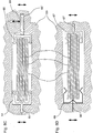
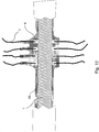
Darüber hinaus ist in
Die Kontaktfahnen
Nach dem Kontaktieren der Kontaktfahnen
Verbleiben nach dem physischen Verbinden Hohlräume im Bereich der Kontaktfahnen
Anstatt einer Spule
Zum Umgießen des Flachleiters
Die Abstandsmittel
Zurückkommend auf die
Eine weitere Möglichkeit der exakten Positionierung des Mehrschichtleiters
Die
Alternativ kann die Abdichtung der Kontaktfahnen
Die
Durch die Verwendung einer Zwei-Komponententechnik kann der Bereich der Kontaktfahnen
Bei der Verwendung eines Zwei-Komponentenverfahrens können die Verbindungselemente entweder aus dem ersten oder aus dem zweiten oder aus einer Mischung von beiden Komponenten hergestellt werden. Die Spritzgießkomponente
Claims (20)
Priority Applications (1)
| Application Number | Priority Date | Filing Date | Title |
|---|---|---|---|
| DE201210217618 DE102012217618A1 (en) | 2012-09-27 | 2012-09-27 | Method for recasting contour flat conductor used in e.g. vehicle, involves inserting and positioning flat conductor in casting tool using spacers to ensure recasting of flat conductor, and recasting flat conductor partly |
Applications Claiming Priority (1)
| Application Number | Priority Date | Filing Date | Title |
|---|---|---|---|
| DE201210217618 DE102012217618A1 (en) | 2012-09-27 | 2012-09-27 | Method for recasting contour flat conductor used in e.g. vehicle, involves inserting and positioning flat conductor in casting tool using spacers to ensure recasting of flat conductor, and recasting flat conductor partly |
Publications (1)
| Publication Number | Publication Date |
|---|---|
| DE102012217618A1 true DE102012217618A1 (en) | 2014-03-27 |
Family
ID=50235290
Family Applications (1)
| Application Number | Title | Priority Date | Filing Date |
|---|---|---|---|
| DE201210217618 Pending DE102012217618A1 (en) | 2012-09-27 | 2012-09-27 | Method for recasting contour flat conductor used in e.g. vehicle, involves inserting and positioning flat conductor in casting tool using spacers to ensure recasting of flat conductor, and recasting flat conductor partly |
Country Status (1)
| Country | Link |
|---|---|
| DE (1) | DE102012217618A1 (en) |
Cited By (7)
| Publication number | Priority date | Publication date | Assignee | Title |
|---|---|---|---|---|
| DE102014004431A1 (en) * | 2014-03-27 | 2015-10-01 | Alanod Gmbh & Co. Kg | Sheathing of profiles with lateral outlets |
| DE102015222582A1 (en) | 2015-11-16 | 2017-05-18 | Lisa Dräxlmaier GmbH | Device for sealing an electrical connection |
| DE102016103439A1 (en) | 2016-02-26 | 2017-08-31 | Lisa Dräxlmaier GmbH | Contact point of a flat conductor |
| DE102016207664A1 (en) * | 2016-05-03 | 2017-11-09 | Continental Teves Ag & Co. Ohg | SENSOR ELEMENT FOR A MOTOR VEHICLE |
| CN107696394A (en) * | 2017-09-21 | 2018-02-16 | 芜湖职业技术学院 | Wire harness and injection moulding apparatus and production method for integrated wall plate |
| WO2018202251A1 (en) | 2017-05-04 | 2018-11-08 | Otto-Von-Guericke-Universität Magdeburg, Patentwesen | Flat conductor for the high voltage direct current connection of off-shore-wind parks |
| DE102022202240A1 (en) | 2022-03-04 | 2023-09-07 | Leoni Bordnetz-Systeme Gmbh | Device for electrical power distribution in a motor vehicle and conductor rail arrangement for a motor vehicle |
Citations (8)
| Publication number | Priority date | Publication date | Assignee | Title |
|---|---|---|---|---|
| DE7617838U1 (en) * | 1976-06-04 | 1976-10-14 | Fa. Carl Freudenberg, 6940 Weinheim | Wiring harness |
| DE3508892A1 (en) * | 1985-03-13 | 1986-09-18 | Stanztechnik Gmbh R + S, 6000 Frankfurt | Mould for producing thin-walled parts |
| DE3710642A1 (en) * | 1987-03-31 | 1988-10-20 | Leonische Drahtwerke Ag | WIRING HARNESS, ESPECIALLY FOR MOTOR VEHICLES |
| US5917151A (en) * | 1997-08-29 | 1999-06-29 | Ut Automotive Dearborn, Inc. | Multi-shot molds for manufacturing wire harnesses |
| US6071446A (en) * | 1997-08-29 | 2000-06-06 | Lear Automotive Dearborn, Inc | Method for centering wire harness in mold |
| DE19923469A1 (en) * | 1999-05-21 | 2000-12-07 | Siemens Ag | Cable loom with end plugs for a motor vehicle has a foamed plastic cover determining the final form of the loom |
| EP1688966A1 (en) * | 2005-02-03 | 2006-08-09 | Auto Kabel Managementgesellschaft mbH | Electrical flat cable for motor vehicles |
| WO2009086992A1 (en) * | 2008-01-07 | 2009-07-16 | Auto-Kabel Managementgesellschaft Mbh | Dimensionally stable wire harness for engine compartment wiring |
-
2012
- 2012-09-27 DE DE201210217618 patent/DE102012217618A1/en active Pending
Patent Citations (8)
| Publication number | Priority date | Publication date | Assignee | Title |
|---|---|---|---|---|
| DE7617838U1 (en) * | 1976-06-04 | 1976-10-14 | Fa. Carl Freudenberg, 6940 Weinheim | Wiring harness |
| DE3508892A1 (en) * | 1985-03-13 | 1986-09-18 | Stanztechnik Gmbh R + S, 6000 Frankfurt | Mould for producing thin-walled parts |
| DE3710642A1 (en) * | 1987-03-31 | 1988-10-20 | Leonische Drahtwerke Ag | WIRING HARNESS, ESPECIALLY FOR MOTOR VEHICLES |
| US5917151A (en) * | 1997-08-29 | 1999-06-29 | Ut Automotive Dearborn, Inc. | Multi-shot molds for manufacturing wire harnesses |
| US6071446A (en) * | 1997-08-29 | 2000-06-06 | Lear Automotive Dearborn, Inc | Method for centering wire harness in mold |
| DE19923469A1 (en) * | 1999-05-21 | 2000-12-07 | Siemens Ag | Cable loom with end plugs for a motor vehicle has a foamed plastic cover determining the final form of the loom |
| EP1688966A1 (en) * | 2005-02-03 | 2006-08-09 | Auto Kabel Managementgesellschaft mbH | Electrical flat cable for motor vehicles |
| WO2009086992A1 (en) * | 2008-01-07 | 2009-07-16 | Auto-Kabel Managementgesellschaft Mbh | Dimensionally stable wire harness for engine compartment wiring |
Cited By (14)
| Publication number | Priority date | Publication date | Assignee | Title |
|---|---|---|---|---|
| US10043601B2 (en) | 2014-03-27 | 2018-08-07 | Lisa Draexlmaier Gmbh | Sheathing of profiles with lateral disposals |
| DE102014004431B4 (en) * | 2014-03-27 | 2016-02-11 | Alanod Gmbh & Co. Kg | Method and device for covering profiles with lateral outlets and profile |
| DE102014004431A1 (en) * | 2014-03-27 | 2015-10-01 | Alanod Gmbh & Co. Kg | Sheathing of profiles with lateral outlets |
| DE102015222582A1 (en) | 2015-11-16 | 2017-05-18 | Lisa Dräxlmaier GmbH | Device for sealing an electrical connection |
| DE102015222582B4 (en) | 2015-11-16 | 2022-03-31 | Lisa Dräxlmaier GmbH | Device for sealing an electrical connection |
| US10096986B2 (en) | 2015-11-16 | 2018-10-09 | Lisa Draexlmaier Gmbh | Device for sealing an electrical connection |
| DE102016103439A1 (en) | 2016-02-26 | 2017-08-31 | Lisa Dräxlmaier GmbH | Contact point of a flat conductor |
| US10027077B2 (en) | 2016-02-26 | 2018-07-17 | Lisa Draexlmaier Gmbh | Contact point for connecting a flat conductor to a conductor element |
| DE102016103439B4 (en) | 2016-02-26 | 2018-04-05 | Lisa Dräxlmaier GmbH | Contact point of a flat conductor |
| US10718640B2 (en) | 2016-05-03 | 2020-07-21 | Continental Teves Ag & Co. Ohg | Sensor element for a motor vehicle |
| DE102016207664A1 (en) * | 2016-05-03 | 2017-11-09 | Continental Teves Ag & Co. Ohg | SENSOR ELEMENT FOR A MOTOR VEHICLE |
| WO2018202251A1 (en) | 2017-05-04 | 2018-11-08 | Otto-Von-Guericke-Universität Magdeburg, Patentwesen | Flat conductor for the high voltage direct current connection of off-shore-wind parks |
| CN107696394A (en) * | 2017-09-21 | 2018-02-16 | 芜湖职业技术学院 | Wire harness and injection moulding apparatus and production method for integrated wall plate |
| DE102022202240A1 (en) | 2022-03-04 | 2023-09-07 | Leoni Bordnetz-Systeme Gmbh | Device for electrical power distribution in a motor vehicle and conductor rail arrangement for a motor vehicle |
Similar Documents
| Publication | Publication Date | Title |
|---|---|---|
| DE102012217618A1 (en) | Method for recasting contour flat conductor used in e.g. vehicle, involves inserting and positioning flat conductor in casting tool using spacers to ensure recasting of flat conductor, and recasting flat conductor partly | |
| EP1697175B1 (en) | Control unit and method for producing the same | |
| EP2467903B1 (en) | Connecting component for electrical conductors and method for sheathing such a connecting component | |
| DE112013005206T5 (en) | Wiring harness and method of manufacturing the outer member of the wiring harness | |
| DE102017215423B4 (en) | Clamp prepositioning, wiring harness and fastening structure of a wiring harness | |
| DE102012100142A1 (en) | Cable harness and method of making the same | |
| DE202015103854U1 (en) | Track for use in the electrical system or as a battery line of vehicles | |
| WO2017045951A1 (en) | Method for producing a cooling device for cooling batteries | |
| EP3002828B1 (en) | Sealing assembly and method for sealing the junction between electrical conductors | |
| DE102016219993A1 (en) | Battery module housing | |
| EP2192655B1 (en) | Tight plug connection for high voltage cables in the automotive industry | |
| DE10054714B4 (en) | Method for sealing a cable or cable set on / in a cable feedthrough element and a cable feedthrough element | |
| EP3275052B1 (en) | Vehicle electrical system component, vehicle equipped with such component and method for producing the same | |
| DE102008031085A1 (en) | Coupling element for plug-in connector for connection to electrical line, has prefabricated housing whose inner space is completely filled with foam body in area of electrical line upto connection side under release of plug side | |
| EP3483991B1 (en) | Method for overmoulding at least two single conductors | |
| EP3340392A1 (en) | Assembly for connection of electrical lines | |
| EP3451463B1 (en) | Assembly for connection of electrical lines | |
| DE102017210373A1 (en) | Waterproof structure of a wiring harness | |
| EP3109953B1 (en) | Assembly comprising a coupling part and an electric line | |
| DE102017210495A1 (en) | Method for manufacturing a wiring harness | |
| EP3582240B1 (en) | Hose closure | |
| DE102016221460B4 (en) | Process for the production of a plug provided with a plastic extrusion coating for a fuel pump to be arranged in a fuel tank of a motor vehicle | |
| DE102007012737B4 (en) | Wiring in motor vehicles | |
| DE102016003325B4 (en) | Method for producing a plastic component having a plurality of carrier parts with at least one electrical conductor track and thus produced plastic component | |
| EP3206268B1 (en) | Method for sealing an electrical coupling element against liquid |
Legal Events
| Date | Code | Title | Description |
|---|---|---|---|
| R163 | Identified publications notified | ||
| R082 | Change of representative | ||
| R012 | Request for examination validly filed | ||
| R016 | Response to examination communication |