Die Erfindung betrifft eine Aktoreinrichtung mit mindestens einem Aktorkolben, dem mindestens eine Feder sowie zwei Elektromagnete zugeordnet sind und der mechanisch mit einer Verstelleinrichtung gekoppelt ist, die durch eine Betätigung der Elektromagnete über den Aktorkolben hydraulisch verstellbar ist. Die Erfindung betrifft des Weiteren eine Axialkolbenmaschine mit mindestens einem Arbeitskolben und einem Stellkolben, die mit einer Schwenkwiege zusammenwirken, die über ein Regelventil verstellbar ist, das eine derartige Aktoreinrichtung umfasst. The invention relates to an actuator device with at least one actuator piston, the at least one spring and two electromagnets are assigned and which is mechanically coupled to an adjusting device which is hydraulically adjustable by actuation of the electromagnets via the actuator piston. The invention further relates to an axial piston machine with at least one working piston and an actuating piston, which cooperate with a pivoting cradle, which is adjustable via a control valve, which comprises such an actuator device.
Stand der TechnikState of the art
Aus den europäischen Patentschriften EP 1 217 209 B1 und EP 1 219 831 B1 sind Verstellvorrichtungen zum Verstellen eines auf das Verdrängungsvolumen einer hydrostatischen Maschine einwirkenden Stellkolbens bekannt. Der Stellkolben ist aus einer durch die Kraft zumindest einer Rückstellfeder vorgegebenen Neutralstellung zwischen zwei Endlagen bewegbar. Zur Regelung von Stelldrücken in Stelldruckkammern ist ein Steuerventil mit einem Steuerkolben vorgesehen. Die Auslenkung des Stellkolbens ist über einen starr mit dem Stellkolben verbundenen Rückführhebel als lineare Bewegung auf eine Federhülse übertragbar, die über eine Steuerfeder in Wirkverbindung steht. Der Steuerkolben besteht in axialer Richtung aus einem ersten Steuerkolbenteil und einem zweiten Steuerkolbenteil, die durch einen Steuerkolbenstößel miteinander verbunden sind. Der erste und der zweite Steuerkolbenteil sind an den voneinander abgewandten Enden durch jeweils zumindest eine Zentrierfeder und/oder Einstellfeder mit einer aufeinander zugerichteten Kraft beaufschlagbar. Zwischen zwei Federsitzkörpern ist eine Steuerfeder gespannt. Die Vorspannung zumindest einer Zentrierfeder und/oder Einstellfeder ist zum Erzeugen in Neutralstellung des Steuerventils ausgeglichener Federkräfte einstellbar. From the European patents EP 1 217 209 B1 and EP 1 219 831 B1 adjusting devices are known for adjusting an acting on the displacement volume of a hydrostatic machine actuator piston. The adjusting piston is movable from a predetermined by the force of at least one return spring neutral position between two end positions. For regulating actuating pressures in actuating pressure chambers, a control valve with a control piston is provided. The deflection of the actuating piston is transferable via a rigidly connected to the actuating piston return lever as a linear movement on a spring sleeve, which is in operative connection via a control spring. The control piston consists in the axial direction of a first control piston part and a second control piston part, which are interconnected by a control piston plunger. The first and the second control piston part can be acted on at the ends remote from each other by at least one centering spring and / or adjusting spring with a mutually directed force. Between two spring seat bodies, a control spring is stretched. The bias of at least one centering spring and / or adjusting spring is adjustable for generating in the neutral position of the control valve balanced spring forces.
Offenbarung der ErfindungDisclosure of the invention
Aufgabe der Erfindung ist es, eine Aktoreinrichtung gemäß dem Oberbegriff des Anspruchs 1, insbesondere im Hinblick auf den benötigten Bauraum und/oder die Funktionalität, vorzugsweise in Kombination mit einer Axialkolbenmaschine, weiter zu verbessern. The object of the invention is to further improve an actuator device according to the preamble of claim 1, in particular with regard to the required installation space and / or the functionality, preferably in combination with an axial piston machine.
Die Aufgabe ist bei einer Aktoreinrichtung mit mindestens einem Aktorkolben, dem mindestens eine Feder sowie zwei Elektromagnete zugeordnet sind und der mechanisch mit einer Verstelleinrichtung gekoppelt ist, die durch eine Betätigung der Elektromagnete über den Aktorkolben hydraulisch verstellbar ist, dadurch gelöst, dass dem Aktorkolben eine vorgespannte Aktorfeder zugeordnet ist, deren Vorspannkraft in einem Kraftbereich unterhalb der Vorspannkraft eine starre Kopplung des Aktorkolbens und eines Kopplungskolbens bewirkt. Bei der Aktoreinrichtung handelt es sich zum Beispiel um ein Stellglied in einer steuerund regelungstechnischen Anwendung. Die Aktoreinrichtung kann aber auch einen Effektor umfassen, der in der Robotik eingesetzt wird. Die Aktoreinrichtung kann dabei sowohl als Betätigungseinrichtung als auch als Antriebseinrichtung, zum Beispiel in einer mechatronischen Anwendung, ausgeführt sein. Die Aktoreinrichtung kann zum Beispiel zum Antrieb einer Fluidmaschine, insbesondere einer Fluidpumpe, verwendet werden. Besonders vorteilhaft ist die Aktoreinrichtung einer Axialkolbenmaschine mit einer Schwenkwiege zugeordnet, die von der Schwenkverstelleinrichtung dargestellt wird. Wenn der Aktorkolben aus seiner Aktormittelstellung heraus bewegt wird, muss zunächst die Federvorspannkraft der Aktorfeder überwunden werden. Dadurch wird die Aktoreinrichtung hinsichtlich ihrer Hysterese im stromlosen Zustand der Elektromagnete optimiert. Beim Zurückstellen des Aktorkolbens im unbestromten Zustand der Elektromagnete wirkt die Federvorspannkraft der Aktorfeder auf den Aktorkolben bis dieser wieder seine Aktormittelstellung erreicht hat. Der Kraftbereich unterhalb der Vorspannkraft der Aktorfeder ist zum Beispiel gegeben, wenn die Elektromagneten beziehungsweise Spulen nicht bestromt sind. Bei unbestromten Magneten beziehungsweise Spulen führt die starre Kopplung zu einem hysteresearmen Zurückstellen der Verstelleinrichtung, insbesondere einem Zurückschwenken einer Schwenkwiege, in ihre Grundstellung. The object is achieved with an actuator device having at least one actuator piston, which is associated with at least one spring and two electromagnets and which is mechanically coupled to an adjusting device which is hydraulically adjustable by actuation of the electromagnets via the actuator piston, characterized in that the actuator piston is a prestressed Associated actuator spring whose biasing force causes a rigid coupling of the actuator piston and a coupling piston in a force range below the biasing force. The actuator device is, for example, an actuator in a control and control application. However, the actuator device may also include an effector used in robotics. The actuator device can be embodied both as an actuating device and as a drive device, for example in a mechatronic application. The actuator device can be used, for example, to drive a fluid machine, in particular a fluid pump. Particularly advantageously, the actuator device is associated with an axial piston machine with a pivoting cradle, which is represented by the Schwenkverstelleinrichtung. When the actuator piston is moved out of its actuator center position, first the spring preload force of the actuator spring must be overcome. As a result, the actuator device is optimized with regard to its hysteresis in the de-energized state of the electromagnets. When resetting the actuator piston in the de-energized state of the electromagnets, the spring biasing force of the actuator spring acts on the actuator piston until it has again reached its actuator center position. The force range below the biasing force of the actuator spring is given, for example, when the electromagnets or coils are not energized. When de-energized magnets or coils, the rigid coupling leads to a hysteresis-poor resetting of the adjusting device, in particular a pivoting back of a pivoting cradle in its normal position.
Ein bevorzugtes Ausführungsbeispiel der Aktoreinrichtung ist dadurch gekennzeichnet, dass die Aktorfeder zwischen zwei Federtellern eingespannt ist, die in axialer Richtung aufeinander zu bewegbar an dem Aktorkolben abgestützt sind. Die axiale Richtung wird durch die Längsachse des Aktorkolbens definiert. Dabei ist der Aktorkolben entlang seiner Längsachse in entgegengesetzten Richtungen aus seiner Aktormittelstellung heraus bewegbar. Über die Federteller kann die Vorspannkraft der Aktorfeder auf einfache Art und Weise auf den Aktorkolben übertragen werden, wenn dieser aus seiner Aktormittelstellung heraus bewegt wird.A preferred embodiment of the actuator device is characterized in that the actuator spring is clamped between two spring plates, which are supported in the axial direction to each other movable on the actuator piston. The axial direction is defined by the longitudinal axis of the actuator piston. In this case, the actuator piston is movable along its longitudinal axis in opposite directions from its Aktorittelstellung out. About the spring plate, the biasing force of the actuator spring can be easily transferred to the actuator piston when it is moved out of its actuator center position.
Ein weiteres bevorzugtes Ausführungsbeispiel der Aktoreinrichtung ist dadurch gekennzeichnet, dass der Aktorkolben unter Zwischenschaltung der Aktorfeder über eine Kopplungseinrichtung mechanisch mit der Verstelleinrichtung gekoppelt ist. Über die Kopplungseinrichtung wird eine Verstellbewegung der Verstelleinrichtung unter Zwischenschaltung der Aktorfeder auf den Aktorkolben übertragen. A further preferred exemplary embodiment of the actuator device is characterized in that the actuator piston is mechanically coupled to the adjusting device by means of a coupling device, with the actuator spring interposed. Via the coupling device, an adjusting movement of the adjusting device is transmitted to the actuator piston with the intermediary of the actuator spring.
Ein weiteres bevorzugtes Ausführungsbeispiel der Aktoreinrichtung ist dadurch gekennzeichnet, dass die Kopplungseinrichtung über die Federteller mechanisch mit dem Aktorkolben gekoppelt ist. Die Federteller sind zu diesem Zweck in entgegengesetzten axialen Richtungen an der Kopplungseinrichtung abgestützt. A further preferred embodiment of the actuator device is characterized in that the coupling device via the Spring plate is mechanically coupled to the actuator piston. The spring plates are supported for this purpose in opposite axial directions on the coupling device.
Ein weiteres bevorzugtes Ausführungsbeispiel der Aktoreinrichtung ist dadurch gekennzeichnet, dass die Kopplungseinrichtung einen Kopplungskolben umfasst, der unter Zwischenschaltung der Aktorfeder mechanisch mit dem Aktorkolben gekoppelt ist. Der Kopplungskolben ist vorzugsweise hülsenartig als Hohlkolben ausgeführt. Dadurch wird auf einfache Art und Weise ermöglicht, einen Ringraum zwischen dem Aktorkolben und dem Kopplungskolben zur Aufnahme der Aktorfeder zu schaffen. A further preferred embodiment of the actuator device is characterized in that the coupling device comprises a coupling piston which is mechanically coupled to the actuator piston with the interposition of the actuator spring. The coupling piston is preferably designed sleeve-like as a hollow piston. This makes it possible in a simple manner to provide an annular space between the actuator piston and the coupling piston for receiving the actuator spring.
Ein weiteres bevorzugtes Ausführungsbeispiel der Aktoreinrichtung ist dadurch gekennzeichnet, dass die Kopplungseinrichtung einen Exzenter, einen Nocken oder eine Kurvenscheibe umfasst, an welcher der Kopplungskolben anliegt. Über den Kopplungskolben kann zum Beispiel eine Schwenkbewegung der Verstelleinrichtung in eine translatorische Bewegung des Kopplungskolbens umgewandelt werden. Der Kopplungskolben kann vorteilhaft mit einer Kopplungsfeder in Anlage an dem Exzenter, dem Nocken oder der Kurvenscheibe gehalten werden. A further preferred embodiment of the actuator device is characterized in that the coupling device comprises an eccentric, a cam or a cam on which the coupling piston rests. For example, a pivoting movement of the adjusting device can be converted into a translatory movement of the coupling piston via the coupling piston. The coupling piston can be advantageously held with a coupling spring in contact with the eccentric, the cam or the cam.
Ein weiteres bevorzugtes Ausführungsbeispiel der Aktoreinrichtung ist dadurch gekennzeichnet, dass die Verstelleinrichtung als Schwenkverstelleinrichtung ausgeführt ist. Die Schwenkverstelleinrichtung ist zum Beispiel als Schwenkwiege einer Axialkolbenmaschine ausgeführt. Die Schwenkwiege der Schwenkverstelleinrichtung ist vorzugsweise um eine Schwenkachse verschwenkbar, wenn einer der Elektromagnete bestromt wird. A further preferred embodiment of the actuator device is characterized in that the adjusting device is designed as a pivoting adjustment. The pivoting adjustment device is designed, for example, as a pivoting cradle of an axial piston machine. The pivoting cradle of the pivoting adjustment device is preferably pivotable about a pivot axis when one of the electromagnets is energized.
Ein weiteres bevorzugtes Ausführungsbeispiel der Aktoreinrichtung ist dadurch gekennzeichnet, dass der Aktorkolben einen Anker und einen Ventilkörper umfasst, der Verbindungen zwischen Hydraulikanschlüssen unterbricht oder freigibt. Der Ventilkörper ist vorzugsweise so angeordnet und ausgeführt, dass die Verbindungen zwischen den Hydraulikanschlüssen unterbrochen werden, wenn sich der Aktorkolben in seiner Mittelstellung befindet. Wenn der Aktorkolben durch Betätigung der Elektromagnete in die eine oder andere Richtung gezogen wird, dann werden unterschiedliche Verbindungen zwischen den Hydraulikanschlüssen freigegeben. A further preferred exemplary embodiment of the actuator device is characterized in that the actuator piston comprises an armature and a valve body which interrupts or releases connections between hydraulic connections. The valve body is preferably arranged and designed so that the connections between the hydraulic connections are interrupted when the actuator piston is in its center position. When the actuator piston is pulled one way or the other by actuation of the solenoids, different connections between the hydraulic ports are released.
Die Erfindung betrifft des Weiteren eine Axialkolbenmaschine mit mindestens einem Arbeitskolben und einem Stellkolben, die mit einer Schwenkwiege zusammenwirken, die über ein Regelventil verstellbar ist, das eine vorab beschriebene Aktoreinrichtung umfasst. Dabei stellt die Schwenkverstelleinrichtung eine Schwenkwiege der Axialkolbenmaschine dar. Der Schwenkwiege ist zusätzlich zu dem Stellkolben vorzugsweise ein Gegenkolben zugeordnet, der permanent gegen die Schwenkwiege drückt, um ein unerwünschtes Spiel auszugleichen. Bei einem Verstellen der Schwenkwiege wird der Gegenkolben durch den Stellkolben überdrückt. Der Stellkolben kann mit Hilfe des Regelventils mit einem Hochdruckniveau oder mit einem Niederdruckniveau der Axialkolbenmaschine verbunden werden. The invention further relates to an axial piston machine having at least one working piston and an actuating piston, which cooperate with a pivoting cradle, which is adjustable via a control valve, which comprises a previously described actuator device. In this case, the Schwenkverstelleinrichtung represents a pivoting cradle of the axial piston machine. The pivoting cradle is in addition to the actuating piston preferably associated with a counter-piston which presses permanently against the pivoting cradle to compensate for unwanted play. When adjusting the pivoting cradle of the counter-piston is suppressed by the actuating piston. The control piston can be connected by means of the control valve to a high pressure level or to a low pressure level of the axial piston engine.
Ein bevorzugtes Ausführungsbeispiel der Axialkolbenmaschine ist dadurch gekennzeichnet, dass das Regelventil als 3/3-Wegeventil ausgeführt ist. Das Regelventil ist vorzugsweise als Proportionalventil ausgeführt. A preferred embodiment of the axial piston machine is characterized in that the control valve is designed as a 3/3-way valve. The control valve is preferably designed as a proportional valve.
Die Axialkolbenmaschine ist vorzugsweise in einem mobilen Hydraulikantrieb zusätzlich zu einer primären Antriebseinheit, zum Beispiel einer Brennkraftmaschine, angeordnet. Der mobile Hydraulikantrieb ist vorzugsweise in einem Hydraulikhybridantriebsstrang eines Hybridfahrzeugs angeordnet. Bei dem Hybridfahrzeug handelt es sich vorzugsweise um einen Personenkraftwagen oder um ein Nutzfahrzeug. The axial piston machine is preferably arranged in a mobile hydraulic drive in addition to a primary drive unit, for example an internal combustion engine. The mobile hydraulic drive is preferably arranged in a hydraulic hybrid drive train of a hybrid vehicle. The hybrid vehicle is preferably a passenger car or a commercial vehicle.
Weitere Vorteile, Merkmale und Einzelheiten der Erfindung ergeben sich aus der nachfolgenden Beschreibung, in der unter Bezugnahme auf die Zeichnung verschiedene Ausführungsbeispiele im Einzelnen beschrieben sind. Further advantages, features and details of the invention will become apparent from the following description in which, with reference to the drawings, various embodiments are described in detail.
Kurze Beschreibung der ZeichnungShort description of the drawing
Es zeigen: Show it:
1 eine vereinfachte Darstellung einer Axialkolbenmaschine mit einer erfindungsgemäßen Aktoreinrichtung und einer Schwenkverstelleinrichtung in einer Mittelstellung; 1 a simplified representation of an axial piston machine with an actuator device according to the invention and a Schwenkverstelleinrichtung in a central position;
2 die Axialkolbenmaschine aus 1 mit einer entgegen dem Uhrzeigersinn ausgeschwenkten Schwenkwiege; 2 the axial piston machine off 1 with a pivoted swivel cradle pivoted counterclockwise;
3 eine vergrößerte Darstellung der Aktoreinrichtung aus 1; 3 an enlarged view of the actuator device 1 ;
4A ein kartesisches Koordinatendiagramm mit einer Federkennlinie zu der Aktoreinrichtung aus 3; 4A a Cartesian coordinate diagram with a spring characteristic to the actuator device 3 ;
4B ein kartesisches Koordinatendiagramm mit einer Federkennlinie zu der Aktoreinrichtung aus den 5–13; 4B a Cartesian coordinate diagram with a spring characteristic to the actuator device from the 5 - 13 ;
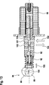
5 eine erfindungsgemäße Aktoreinrichtung im Längsschnitt und die Figuren die Aktoreinrichtung aus 5 in verschiedenen Schaltstellungen und 6 bis 13 Zuständen. 5 an actuator device according to the invention in longitudinal section and the figures of the actuator device 5 in different switch positions and 6 to 13 States.
Beschreibung der Ausführungsbeispiele Description of the embodiments
In den 1 bis 3 ist eine erfindungsgemäße Aktoreinrichtung 1 in Kombination mit einer Axialkolbenmaschine in verschiedenen Zuständen und Ansichten dargestellt. Die Aktoreinrichtung 1 stellt im dargestellten Ausführungsbeispiel ein Regelventil der Axialkolbenmaschine dar. Zu diesem Zweck umfasst die Aktoreinrichtung 1 einen Aktorkolben 2, der in einem Führungskörper 3 hin und her bewegbar geführt ist. In the 1 to 3 is an actuator device according to the invention 1 shown in different states and views in combination with an axial piston machine. The actuator device 1 represents in the illustrated embodiment, a control valve of the axial piston machine. For this purpose, the actuator device comprises 1 an actuator piston 2 who is in a leadership body 3 is guided back and forth movable.
Die Axialkolbenmaschine umfasst des Weiteren eine Schwenkverstelleinrichtung 4, die mit Hilfe einer Kopplungseinrichtung 5 mechanisch mit der Aktoreinrichtung 1 gekoppelt ist. Die Kopplungseinrichtung 5 umfasst einen Exzenter 8, an dem ein in den 1 bis 3 oberes Ende eines Kopplungskolbens 9 anliegt. Der Kopplungskolben 9 ist, wie durch einen Doppelpfeil 10 angedeutet ist, in Längsrichtung von unten nach oben in Richtung einer Aktorachse 14 translatorisch hin und her bewegbar. The axial piston machine further comprises a pivoting adjustment device 4 using a coupling device 5 mechanically with the actuator device 1 is coupled. The coupling device 5 includes an eccentric 8th , in which one in the 1 to 3 Upper end of a coupling piston 9 is applied. The coupling piston 9 is like a double arrow 10 is indicated, in the longitudinal direction from bottom to top in the direction of an actuator axis 14 translatable back and forth.
Der Aktorkolben 2 ist in Längsrichtung, das heißt in Richtung der Aktorachse 14, zwischen einer Kopplungsfeder 11 und einer Aktorfeder 12 eingespannt. Die Kopplungsfeder 11 ist zwischen dem Kopplungskolben 9 und dem in den 1 bis 3 oberen Ende des Aktorkolbens 2 angeordnet. Die Aktorfeder 12 ist zwischen dem in den 1 bis 3 unteren Ende des Aktorkolbens 2 beziehungsweise einem Anker 40 und einem Einstellelement 13 angeordnet. Das Einstellelement 13 ist in ein Aktorgehäuse 16 eingeschraubt oder eingepresst. The actuator piston 2 is in the longitudinal direction, that is in the direction of the actuator axis 14 , between a coupling spring 11 and an actuator spring 12 clamped. The coupling spring 11 is between the coupling piston 9 and in the 1 to 3 upper end of the actuator piston 2 arranged. The actuator spring 12 is between in the 1 to 3 lower end of the actuator piston 2 or an anchor 40 and a setting element 13 arranged. The adjustment element 13 is in an actuator housing 16 screwed or pressed.
Das Aktorgehäuse 16 ist an ein Maschinengehäuse 17 der Axialkolbenmaschine angebaut und umfasst zwei elektromagnetische Spulen 18, 19. Die elektromagnetischen Spulen 18, 19 stellen zwei Elektromagneten dar, die zur Betätigung der Aktoreinrichtung 1 bestromt werden. The actuator housing 16 is on a machine housing 17 the axial piston machine and includes two electromagnetic coils 18 . 19 , The electromagnetic coils 18 . 19 represent two electromagnets that are used to actuate the actuator device 1 be energized.
Wenn die elektromagnetische Spule 18 bestromt wird, dann wird der Aktorkolben 2 in den 1 bis 3 nach oben gezogen, das heißt, auf den Exzenter 8 zu. Wenn die elektromagnetische Spule 19 bestromt wird, dann wird der Aktorkolben 2 in den 1 bis 3 nach unten gezogen, das heißt, von dem Exzenter 8 weg auf das Einstellelement 13 zu. When the electromagnetic coil 18 is energized, then the actuator piston 2 in the 1 to 3 Pulled up, that is, on the eccentric 8th to. When the electromagnetic coil 19 is energized, then the actuator piston 2 in the 1 to 3 pulled down, that is, from the eccentric 8th away on the adjustment 13 to.
Die Schwenkverstelleinrichtung 4 der Axialkolbenmaschine ist als Schwenkwiege 20 ausgeführt, die, wie durch einen Doppelpfeil 21 angedeutet ist, um eine Schwenkachse 22 schwenkbar ist. Die Schwenkachse 22 ist in den 1 bis 3 senkrecht zur Zeichenebene angeordnet. The pivoting adjustment 4 the axial piston machine is as a pivoting cradle 20 running, as by a double arrow 21 is indicated, about a pivot axis 22 is pivotable. The pivot axis 22 is in the 1 to 3 arranged perpendicular to the plane of the drawing.
Die Arbeitskolben 25, 26 sind in einer Trommel geführt, die um eine Drehachse 24 drehbar ist. Die Trommel mit den Arbeitskolben wird auch als Triebwerk bezeichnet. Demzufolge wird die Drehachse 24 auch als Triebwerkdrehachse 24 bezeichnet. Die Triebwerkdrehachse 24 verläuft senkrecht zur Aktorachse 14. Der Mittelpunkt des Exzenters 8 ist von einem Schnittpunkt beabstandet, in welchem sich die Schwenkachse 22 und die Triebwerkdrehachse 24 der Trommel schneiden. The working pistons 25 . 26 are guided in a drum around an axis of rotation 24 is rotatable. The drum with the working piston is also referred to as an engine. As a result, the rotation axis becomes 24 also as engine rotation axis 24 designated. The engine rotation axis 24 runs perpendicular to the actuator axis 14 , The center of the eccentric 8th is spaced from an intersection, in which the pivot axis 22 and the engine's axis of rotation 24 cut the drum.
Die Axialkolbenmaschine umfasst mindestens zwei, vorzugsweise mehr als zwei, Arbeitskolben 25, 26, die mit ihren in den 1 bis 3 linken Enden an der Schwenkwiege 20 anliegen. Die in den 1 bis 3 rechten Enden der Arbeitskolben 25, 26 begrenzen Arbeitsdruckräume der Axialkolbenmaschine, die mit einem Hydraulikmedium, wie Hydrauliköl, gefüllt sind. Der Aufbau und die Funktion einer Axialkolbenmaschine werden als bekannt vorausgesetzt. The axial piston machine comprises at least two, preferably more than two, working pistons 25 . 26 that with their in the 1 to 3 left ends on the pivoting cradle 20 issue. The in the 1 to 3 right ends of the working piston 25 . 26 limit working pressure chambers of the axial piston machine, which are filled with a hydraulic medium such as hydraulic oil. The structure and function of an axial piston machine are assumed to be known.
Wie durch den Doppelpfeil 21 angedeutet ist, kann die Schwenkwiege 20 um begrenzte Schwenkwinkel um die Schwenkachse 22 verschwenkt werden, um den Hub der Arbeitskolben 25, 26 zu verstellen. In den 1 und 3 ist die Schwenkwiege 20 in ihrer Mittelstellung dargestellt. In der Mittelstellung ist die Schwenkwiege 20 mit einer Schwenkwiegenachse 27 senkrecht zu der Drehachse 24 der Trommel und parallel zu der Aktorachse 14 angeordnet. As by the double arrow 21 is indicated, the pivoting cradle 20 by limited pivoting angle about the pivot axis 22 be pivoted to the stroke of the working piston 25 . 26 to adjust. In the 1 and 3 is the pivoting cradle 20 shown in their middle position. In the middle position is the pivoting cradle 20 with a swivel weighing axis 27 perpendicular to the axis of rotation 24 the drum and parallel to the actuator axis 14 arranged.
In 2 ist die Schwenkwiege 20 entgegen dem Uhrzeigersinn ausgeschwenkt. Das Verschwenken der Schwenkwiege 20 wird durch einen Stellkolben 28 bewirkt, der radial außerhalb der Arbeitskolben 25, 26 an der Schwenkwiege 20 angreift. Der Stellkolben 28 ist in den 1 und 2 oben angeordnet. An seinem der Schwenkwiege 20 abgewandten Ende ist der Stellkolben 28 mit einem Stelldruck beaufschlagbar, der über die als Regelventil ausgeführte Aktoreinrichtung 1 eingestellt beziehungsweise geregelt wird. In 2 is the pivoting cradle 20 swung out counterclockwise. The pivoting of the swivel cradle 20 is by an actuating piston 28 causes the radially outside of the working piston 25 . 26 at the swivel cradle 20 attacks. The adjusting piston 28 is in the 1 and 2 arranged above. At his the swivel cradle 20 opposite end is the actuator piston 28 acted upon by a control pressure, via the designed as a control valve actuator device 1 is set or regulated.
Die Schwenkwiege 20 ist in den 1 und 2 unten des Weiteren mit einem Gegenkolben 29 beaufschlagt, der mit seinem in den 1 und 2 linken Ende an der Schwenkwiege 20 anliegt. Der Gegenkolben 29 ist an seinem der Schwenkwiege 20 abgewandten Ende mit einem Hochdruck beaufschlagt, der durch die Axialkolbenmaschine erzeugt wird. The pivoting cradle 20 is in the 1 and 2 below further with an opposed piston 29 charged with his in the 1 and 2 left end on the swivel cradle 20 is applied. The opposing piston 29 is at its the pivot cradle 20 facing away from the end with a high pressure, which is generated by the axial piston machine.
Der Stellkolben 28 und der Gegenkolben 29 sind, ebenso wie die Arbeitskolben 25, 26 parallel zur der Drehachse 24 der Axialkolbenmaschine translatorisch hin und her bewegbar. Dem Stellkolben 28 ist eine Stellfeder 30 zugeordnet. Dem Gegenkolben 29 ist eine Gegenfeder 31 zugeordnet. Durch die beiden Federn 30, 31 werden die beiden Kolben 28, 29 in Anlage an der Schwenkwiege 20 gehalten. The adjusting piston 28 and the opposing piston 29 are, as well as the power pistons 25 . 26 parallel to the axis of rotation 24 the axial piston machine translationally back and forth. The adjusting piston 28 is a spring 30 assigned. The counter-piston 29 is a counter-spring 31 assigned. Through the two springs 30 . 31 be the two pistons 28 . 29 in contact with the swivel cradle 20 held.
Die in den 1 und 2 dargestellte Axialkolbenmaschine kann besonders vorteilhaft sowohl als Axialkolbenpumpe als auch als Axialkolbenmotor arbeiten. Wenn sich die Schwenkwiege in ihrer in 1 dargestellten Mittelstellung befindet, führen die Arbeitskolben 25, 26 im Betrieb der Axialkolbenmaschine keinen Hub aus. Wenn die Schwenkwiege 20, wie in 2 dargestellt ist, um etwa zwanzig Grad um ihre Schwenkachse 22 ausgeschwenkt ist, dann führen die Arbeitskolben 25, 26 einen maximalen Hub aus. The in the 1 and 2 shown axial piston machine can work particularly advantageous both as axial piston pump and as axial piston. When the pivoting cradle in its in 1 shown center position, lead the working piston 25 . 26 no stroke during operation of the axial piston machine. If the swivel cradle 20 , as in 2 is shown at about twenty degrees about its pivot axis 22 is swung out, then lead the working piston 25 . 26 a maximum stroke.
An Axialkolbenmotoren wird der Schwenkwiegenwinkel als Stellgröße für die Drehzahl und das erzeugte Drehmoment an einer Abtriebswelle der Axialkolbenmaschine genutzt. An Axialkolbenpumpen hingegen wird der Schwenkwiegenwinkel als Stellgröße für das Fördervolumen und den Druck genutzt. On axial piston motors, the pivotal weighing angle is used as a manipulated variable for the speed and the torque generated on an output shaft of the axial piston machine. On the other hand, on axial piston pumps, the swivel weighing angle is used as a control variable for the delivery volume and pressure.
Bei der in den 1 und 2 dargestellten Axialkolbenmaschine wird die Verstellung der Schwenkwiege 20 bei stromlosen Spulen 18, 19 anhand der Position des Exzenters 8 durchgeführt, der an der Schwenkwiege 20 angebracht ist. Der Kopplungskolben 9, der auf die Kopplungsfeder 11 wirkt, folgt einer Bewegung des Exzenters 8. In the in the 1 and 2 The axial piston machine shown is the adjustment of the pivoting cradle 20 with de-energized coils 18 . 19 based on the position of the eccentric 8th performed at the pivoting cradle 20 is appropriate. The coupling piston 9 pointing to the coupling spring 11 acts, follows a movement of the eccentric 8th ,
Der Weg, den der Kopplungskolben 9 beim Verschwenken der Schwenkwiege 20 von dem in 1 dargestellten minimalen Schwenkwinkel bis zu dem in 2 dargestellten maximalen Schwenkwinkel zurücklegt, kann durch den Exzenter 8 im Vergleich zu herkömmlichen Axialkolbenmaschinen reduziert werden. Dadurch kann die axiale Ausdehnung der Axialkolbenmaschine in Richtung der Drehachse 24 reduziert werden. Die axiale Ausdehnung der Axialkolbenmaschine in Richtung der Drehachse 24 wird auch als Axialkolbenmaschinenbaulänge bezeichnet. The way the coupling piston 9 when pivoting the pivoting cradle 20 from the in 1 shown minimum swivel angle up to the in 2 represented maximum pivoting angle can, through the eccentric 8th be reduced compared to conventional axial piston machines. As a result, the axial extent of the axial piston machine in the direction of the axis of rotation 24 be reduced. The axial extent of the axial piston machine in the direction of the axis of rotation 24 is also referred to as Axialkolbenmaschinenbaulänge.
Darüber hinaus ist die als Regelventil ausgeführte Aktoreinrichtung 1 radial zur Drehachse 24 der Axialkolbenmaschine angeordnet. Radial bedeutet quer zur Drehachse 24, das heißt, die Aktorachse 14 ist senkrecht zur Drehachse 24 angeordnet. Durch die radiale Anordnung der Aktoreinrichtung 1 kann die Axialkolbenmaschinenbaulänge in Richtung der Drehachse 24 weiter reduziert werden. In addition, the designed as a control valve actuator device 1 radial to the axis of rotation 24 the axial piston machine arranged. Radial means transverse to the axis of rotation 24 that is, the actuator axis 14 is perpendicular to the axis of rotation 24 arranged. Due to the radial arrangement of the actuator device 1 can the Axialkolbenmaschinenbaulänge in the direction of the axis of rotation 24 be further reduced.
Die Verstellung des Schwenkwinkels erfolgt mit Hilfe des Stellkolbens 28 und des Gegenkolbens 29, die jeweils ein entgegengesetztes Moment an der Schwenkwiege 20 erzeugen. Der Stellkolben 28 kann mit Hilfe der als Regelventil ausgeführten Aktoreinrichtung 1 mit dem Hochdruckniveau oder mit einem Niederdruckniveau der Axialkolbenmaschine verbunden werden. Als Hochdruck wird der Druck bezeichnet, der mit Hilfe der Arbeitskolben 25, 26 im Betrieb der Axialkolbenmaschine erzeugt wird. Als Niederdruck wird zum Beispiel ein Tankdruck bezeichnet, der dem Umgebungsdruck entsprechen kann. The adjustment of the swivel angle takes place with the aid of the adjusting piston 28 and the counter-piston 29 , each having an opposite moment on the pivoting cradle 20 produce. The adjusting piston 28 can with the help of designed as a control valve actuator device 1 be connected to the high pressure level or to a low pressure level of the axial piston machine. High pressure is the pressure that is generated by the working pistons 25 . 26 is generated during operation of the axial piston machine. As a low pressure, for example, a tank pressure is referred to, which may correspond to the ambient pressure.
Das durch die Aktoreinrichtung 1 dargestellte Regelventil entspricht einem 3/3-Wegeventil mit einem Niederdruckanschluss oder Tankdruckanschluss 34, einem Hochdruckanschluss oder Pumpendruckanschluss 35 und einem Steuerdruckanschluss oder Arbeitsdruckanschluss 36. An dem Aktorkolben 2 ist ein Ventilkörper 38 ausgebildet. Der Ventilkörper 38 ist einstückig mit dem Aktorkolben 2 verbunden. Der Aktorkolben 2 mit dem Ventilkörper 38 ist zwischen zwei Endstellungen in Richtung der Aktorachse 14 translatorisch hin und her bewegbar. In einer in 1 dargestellten Mittelstellung des Aktorkolbens 2 verschließt der Ventilkörper 38 des Aktorkolbens 2 den Steuerdruckanschluss 36. That through the actuator device 1 shown control valve corresponds to a 3/3-way valve with a low pressure connection or tank pressure connection 34 , a high-pressure connection or pump pressure connection 35 and a pilot pressure port or working pressure port 36 , On the actuator piston 2 is a valve body 38 educated. The valve body 38 is integral with the actuator piston 2 connected. The actuator piston 2 with the valve body 38 is between two end positions in the direction of the actuator axis 14 translatable back and forth. In an in 1 shown center position of the actuator piston 2 closes the valve body 38 of the actuator piston 2 the control pressure connection 36 ,
Wenn die Spule 18 bestromt wird, dann wird der mit dem Aktorkolben 2 gekoppelte Anker 40 in den 1 bis 3 nach oben, das heißt von dem Einstellelement 13 weg auf den Exzenter 8 zu gezogen. Der Anker 40 ist im dargestellten Ausführungsbeispiel als separates Teil ausgeführt und wird durch die Vorspannkraft der Federn 11 und 12 in Anlage an dem Aktorkolben 2 gehalten. Der Anker 40 kann aber auch einstückig mit dem Aktorkolben 2 verbunden sein. Dabei gibt der Ventilkörper 38 eine Verbindung zwischen Druckanschluss oder Pumpenanschluss 35 und dem Steuerdruckanschluss oder Arbeitsdruckanschluss 36 des Regelventils zum Stellkolben 28 frei. Als Folge dessen wird die Schwenkwiege 20, wie man in 2 sieht, gegen den Uhrzeigersinn bis in ihre Endlage verschwenkt. Die Kopplungsfeder 11 und die Aktorfeder 12 sind so ausgelegt, dass der Aktorkolben 2 bei bestromter Spule 18 seine Mittelstellung erreicht, wenn die Schwenkwiege 20 gegen den Uhrzeigersinn in ihre Schwenkwiegenendlage verschwenkt ist. If the coil 18 is energized, then with the actuator piston 2 coupled anchor 40 in the 1 to 3 upwards, that is from the adjusting element 13 away on the eccentric 8th to pulled. The anchor 40 is executed in the illustrated embodiment as a separate part and is characterized by the biasing force of the springs 11 and 12 in contact with the actuator piston 2 held. The anchor 40 but can also be integral with the actuator piston 2 be connected. The valve body is there 38 a connection between pressure connection or pump connection 35 and the pilot pressure port or working pressure port 36 the control valve to the actuator piston 28 free. As a result, the pivot cradle 20 how to get in 2 sees, pivoted counterclockwise to its final position. The coupling spring 11 and the actuator spring 12 are designed so that the actuator piston 2 with energized coil 18 its middle position is reached when the pivoting cradle 20 is pivoted counterclockwise in their Schwenkwiegenendlage.
Wenn die Spule 18 stromlos ist und die Spule 19 bestromt wird, dann wird der Anker 40 in den 1 bis 3 nach unten, das heißt von dem Exzenter 8 weg auf das Einstellelement 13 zu gezogen. Dabei gibt der Ventilkörper 38 eine Verbindung zwischen dem Niederdruckanschluss oder Tankdruckanschluss 34 und dem Steuerdruckanschluss oder Arbeitsdruckanschluss 36 zum Stellkolben 28 frei. Als Folge dessen wird die Schwenkwiege 20 im Uhrzeigersinn bis in ihre (nicht dargestellte) Endlage verschwenkt. Die Kopplungsfeder 11 und die Aktorfeder 12 sind so ausgelegt, dass der Aktorkolben 2 bei bestromter Spule 19 seine Mittelstellung erreicht, wenn die Schwenkwiege 20 im Uhrzeigersinn in ihre Schwenkwiegenendlage verschwenkt ist. If the coil 18 is dead and the coil 19 energized, then becomes the anchor 40 in the 1 to 3 down, that is from the eccentric 8th away on the adjustment 13 to pulled. The valve body is there 38 a connection between the low pressure port or tank pressure port 34 and the pilot pressure port or working pressure port 36 to the adjusting piston 28 free. As a result, the pivot cradle 20 pivoted clockwise to its (not shown) end position. The coupling spring 11 and the actuator spring 12 are designed so that the actuator piston 2 with energized coil 19 its middle position is reached when the pivoting cradle 20 is pivoted in a clockwise direction in their Schwenkwiegenendlage.
Wenn die beiden Spulen 18, 19 stromlos sind, wird die Lage des Aktorkolbens 2 von der Kopplungsfeder 11 und der Aktorfeder 12 vorgegeben. Dabei ist die Kopplungsfeder 11 an ihrem in den 1 bis 3 oben Ende über den Kopplungskolben 9 mit dem Exzenter 8 verbunden und folgt somit dessen Bewegungen, die durch den Doppelpfeil 10 angedeutet sind. If the two coils 18 . 19 are de-energized, the position of the actuator piston is 2 from the coupling spring 11 and the actuator spring 12 specified. Here is the coupling spring 11 at her in the 1 to 3 above end over the coupling piston 9 with the eccentric 8th connected and thus follows its movements by the double arrow 10 are indicated.
Wenn die Schwenkwiege 20, wie man in 2 sieht, bei stromlosen Spulen 18, 19 gegen den Uhrzeigersinn verschwenkt ist, wird der Aktorkolben 2 von der Kopplungsfeder 11 nach unten gedrückt, und der Stellkolben 28 wird über den Arbeitsdruckanschluss 36 mit dem Niederdruckanschluss 34 verbunden. Als Folge dessen wird die Schwenkwiege 20 im Uhrzeigersinn in Richtung Mittelstellung geschwenkt, was als Mittenzentrierung der Schwenkwiege 20 bezeichnet wird. If the swivel cradle 20 how to get in 2 sees, with de-energized coils 18 . 19 is pivoted counterclockwise, the actuator piston 2 from the coupling spring 11 pressed down, and the actuator piston 28 is via the working pressure connection 36 with the low pressure connection 34 connected. As a result, the pivot cradle 20 pivoted clockwise towards the center position, which serves as centering of the pivoting cradle 20 referred to as.
Die Kopplungsfeder 11 und die Aktorfeder 12 sind vorteilhaft so ausgelegt, dass bei stromlosen Spulen 18, 19 mit Erreichen der Schwenkwiegenmittelstellung auch der Aktorkolben 2 seine Mittelstellung erreicht, wodurch die Verbindung zum Stellkolben 28 durch den Ventilkörper 38 geschlossen wird. The coupling spring 11 and the actuator spring 12 are advantageously designed so that when de-energized coils 18 . 19 with reaching the Schwenkwiegenmittelstellung and the actuator piston 2 reaches its middle position, whereby the connection to the actuating piston 28 through the valve body 38 is closed.
Ist die Schwenkwiege 20 bei stromlosen Spulen 18, 19 im Uhrzeigersinn ausgeschwenkt (nicht dargestellt), wird der Aktorkolben 2, der auch als Ventilkolben bezeichnet wird, von der Aktorfeder 12 von dem Einstellelement 13 weg in den 1 bis 3 nach oben gedrückt, wodurch der Stellkolben 28 mit dem Druckanschluss oder Pumpendruckanschluss 35 verbunden und mit Hochdruck beaufschlagt wird. Als Folge dessen wird die Schwenkwiege 20 entgegen dem Uhrzeigersinn verschwenkt. Dabei sind die Kopplungsfeder 11 und die Aktorfeder 12 vorteilhaft so ausgelegt, dass mit Erreichen der Schwenkwiegenmittelstellung auch der Ventilkolben oder Aktorkolben 2 seine Mittelstellung erreicht und somit die Verbindung vom Druckanschluss oder Pumpendruckanschluss 35 zum Stellkolben 28 geschlossen wird. Is the swing cradle 20 with de-energized coils 18 . 19 swung clockwise (not shown), the actuator piston 2 , which is also referred to as a valve piston, from the actuator spring 12 from the adjusting element 13 away in the 1 to 3 pushed up, causing the actuator piston 28 with the pressure connection or pump pressure connection 35 connected and subjected to high pressure. As a result, the pivot cradle 20 pivoted counterclockwise. Here are the coupling spring 11 and the actuator spring 12 Advantageously designed so that when reaching the Schwenkwiegenmittelstellung and the valve piston or actuator piston 2 reaches its middle position and thus the connection from the pressure port or pump pressure port 35 to the adjusting piston 28 is closed.
Mit der in 3 dargestellten Aktoreinrichtung 1 wird die Schwenkwiege 20 bei stromlosen Spulen 18, 19 hydraulisch in ihre Mittenstellung oder Mittelstellung beziehungsweise Grundstellung zurückgestellt. Wenn sich der Aktorkolben 2 in seiner Mittenstellung oder Mittelstellung befindet und die Schwenkwiege ihre Mittenstellung, Mittelstellung oder Grundstellung einnimmt, das heißt nicht angeschwenkt oder verschwenkt ist, heben sich die Stellkräfte der Kopplungsfeder 11 und der Aktorfeder 12 auf. Somit wirkt in der Mittenstellung oder Mittelstellung des Ventilkolbens oder Aktorkolbens 2 im stromlosen Zustand der Spulen 18, 19 keine Stellkraft auf den Aktorkolben 2. With the in 3 shown actuator device 1 becomes the pivoting cradle 20 with de-energized coils 18 . 19 hydraulically reset to its center position or middle position or home position. When the actuator piston 2 is in its center position or center position and the pivoting cradle assumes its center position, middle position or home position, that is not swiveled or pivoted, the actuating forces of the coupling spring lift 11 and the actuator spring 12 on. Thus acts in the middle position or middle position of the valve piston or actuator piston 2 in the de-energized state of the coils 18 . 19 no force on the actuator piston 2 ,
Wenn der Aktorkolben 2 aus der Mittenstellung oder Mittelstellung heraus bewegt wird, dann steigt die Kraft, die auf den Aktorkolben 2 wirkt annähernd linear an. Durch das Einstellelement 13 kann die Schwenkwiegenmittelstellung von außen eingestellt werden. Neben der Mittenzentrierung der Schwenkwiege 20 bei stromlosen Spulen 18, 19 führt die Kopplung der Schwenkwiegenstellung mit der Aktoreinrichtung 1 zu einer positiven Beeinflussung der Regelcharakteristik. When the actuator piston 2 is moved out of the center position or center position, then increases the force on the actuator piston 2 acts almost linearly. Through the adjustment element 13 the swinging balance can be adjusted from the outside. In addition to the centering of the pivoting cradle 20 with de-energized coils 18 . 19 leads the coupling of the Schwenkweepingstellung with the actuator device 1 to a positive influence on the control characteristic.
Die in 3 dargestellte Aktoreinrichtung 1 funktioniert wie folgt. Die Schwenkwiege 20 befindet sich in der dargestellten Grundstellung, solange die Elektromagneten beziehungsweise elektromagnetischen Spulen 18, 19 nicht bestromt sind. Die Grundstellung wird auch als Nullstellung oder Nullförderstellung bezeichnet, weil in der Grundstellung keine Förderung stattfindet. Die Grundstellung kann auch geringfügig von der Nullförderstellung abweichen, das heißt, die Schwenkwiege 20 kann in ihrer Grundstellung geringfügig, zum Beispiel bis zu 10 Prozent Fördervolumen, ausgeschwenkt sein.In the 3 illustrated actuator device 1 works as follows. The pivoting cradle 20 is in the illustrated basic position, as long as the electromagnet or electromagnetic coils 18 . 19 are not energized. The basic position is also referred to as zero position or zero production position, because in the basic position no promotion takes place. The basic position may also deviate slightly from the zero feed position, that is, the pivoting cradle 20 may in its basic position slightly, for example up to 10 Percentage volume, be swung out.
Der Aktorkolben 2 befindet sich in seiner Mittelstellung oder Grundstellung, wenn der Ventilkörper 38 den Steuerdruckanschluss 36 verschließt. Wenn die Spule 18 bestromt wird, dann bewegt sich der Anker 40 in 3 nach oben. Dabei gibt der Ventilkörper 38 die Verbindung zwischen dem Pumpendruckanschluss 35 und dem Steuerdruckanschluss 36 frei. Dadurch wird der Stellkolben der Schwenkwiege 20 mit dem Pumpendruck beaufschlagt, so dass der Stellkolben die Schwenkwiege 20 im Gegenuhrzeigersinn verschwenkt. The actuator piston 2 is in its middle position or home position when the valve body 38 the control pressure connection 36 closes. If the coil 18 energized, then the anchor moves 40 in 3 up. The valve body is there 38 the connection between the pump pressure connection 35 and the control pressure port 36 free. As a result, the actuator piston of the pivoting cradle 20 acted upon by the pump pressure, so that the actuator piston, the pivoting cradle 20 pivoted counterclockwise.
Durch das Verschwenken der Schwenkwiege 20 wird der Kopplungskolben 9 in 3 nach unten bewegt. Diese Bewegung des Kopplungskolbens 9 wird über die Kopplungsfeder 11 auf den Aktorkolben 2 übertragen, der sich wiederum gegen die Vorspannkraft der Aktorfeder 12 nach unten bewegt, bis der Ventilkörper 38 den Steuerdruckanschluss 36 verschließt. In diesem Zustand bilden die Federkräfte der Federn 11, 12 und die Magnetkraft ein Kräftegleichgewicht.By pivoting the swivel cradle 20 becomes the coupling piston 9 in 3 moved down. This movement of the coupling piston 9 is via the coupling spring 11 on the actuator piston 2 in turn, against the biasing force of the actuator spring 12 moves down until the valve body 38 the control pressure connection 36 closes. In this state, the spring forces of the springs form 11 . 12 and the magnetic force is an equilibrium of forces.
So kann durch ein definiertes Bestromen der Spulen 18, 19 ein Verschwenken der Schwenkwiege 20 um einen definierten Schwenkwinkel erreicht werden. Wenn die Spule 18 stromlos geschaltet wird, dann bewegt sich der Anker 4 durch die Federkräfte der Federn 11, 12 und im Zusammenspiel des Ventilkörpers 38 mit den Anschlüssen 34 bis 36 wieder in seine Ausgangsstellung zurück und die Schwenkwiege 20 nimmt wieder ihre Grundstellung ein.So can by a defined energizing the coils 18 . 19 a pivoting of the pivoting cradle 20 can be achieved by a defined swivel angle. If the coil 18 de-energized then the armature moves 4 by the spring forces of the springs 11 . 12 and in the interaction of the valve body 38 with the connections 34 to 36 back to its original position and the pivoting cradle 20 resumes her basic position.
In 4A ist ein kartesisches Koordinatendiagramm mit einer x-Achse 41 und einer y-Achse 42 dargestellt. Auf der x-Achse 41 ist der Weg des Aktorkolbens 2 in einer geeigneten Wegeinheit aufgetragen. Auf der y-Achse 42 ist die kombinierte Federkraft der Kopplungsfeder 11 und der Aktorfeder 12 in einer geeigneten Krafteinheit aufgetragen, wobei sich der Kopplungskolben in seiner Nullstellung befindet. Durch eine Linie 44 ist eine kombinierte Federkennlinie für die Kopplungsfeder 11 und die Aktorfeder 12 aufgetragen. Durch Punkte 45, 46 sind die maximalen Verstellwege des Aktorkolbens 2 angedeutet. Der Koordinatenursprung entspricht der Mittelstellung des Aktorkolbens 2. In 4A is a Cartesian coordinate plot with an x-axis 41 and a y-axis 42 shown. On the x-axis 41 is the way of the actuator piston 2 applied in a suitable path unit. On the y-axis 42 is the combined spring force of the coupling spring 11 and the actuator spring 12 applied in a suitable power unit, wherein the coupling piston is in its zero position. Through a line 44 is a combined spring characteristic for the coupling spring 11 and the actuator spring 12 applied. By points 45 . 46 are the maximum adjustment of the actuator piston 2 indicated. The origin of the coordinates corresponds to the center position of the actuator piston 2 ,
In 4b ist ein kartesisches Koordinatendiagramm mit einer x-Achse 241 und einer y-Achse 242 dargestellt. Auf der x-Achse 241 ist der Weg eines Aktorkolbens 82 einer erfindungsgemäßen Aktoreinrichtung 81, die in den 5–13 dargestellt ist, in einer geeigneten Wegeinheit aufgetragen. Auf der y-Achse 242 ist die kombinierte Federkraft einer Kopplungsfeder 91 und einer Aktorfeder 92 in einer geeigneten Krafteinheit aufgetragen, wobei sich der Kopplungskolben in seiner Nullstellung befindet. Durch eine Linie 244 ist eine kombinierte Federkennlinie für die Kopplungsfeder 91 und die Aktorfeder 92 aufgetragen. Durch Punkte 245, 246 sind die maximalen Verstellwege des Aktorkolbens 82 angedeutet. Der Koordinatenursprung entspricht der Mittelstellung des Aktorkolbens 92.In 4b is a Cartesian coordinate plot with an x-axis 241 and a y-axis 242 shown. On the x-axis 241 is the way of an actuator piston 82 an actuator device according to the invention 81 that in the 5 - 13 is shown, applied in a suitable path unit. On the y-axis 242 is the combined spring force of a coupling spring 91 and an actuator spring 92 applied in a suitable power unit, wherein the coupling piston is in its zero position. Through a line 244 is a combined spring characteristic for the coupling spring 91 and the actuator spring 92 applied. By points 245 . 246 are the maximum adjustment of the actuator piston 82 indicated. The origin of the coordinates corresponds to the center position of the actuator piston 92 ,
Die Aktorfeder 92 ist vorgespannt. Wenn der Aktorkolben 82 aus seiner Mittenstellung oder Mittelstellung bewegt wird, muss zunächst die Federvorspannkraft überwunden werden. Beim Zurückstellen des Aktorkolbens 82 im unbestromten Zustand wirkt diese Federvorspannkraft bis zum Erreichen der Mittenstellung. Hierdurch wird einen geringere Hysterese erreicht.The actuator spring 92 is biased. When the actuator piston 82 is moved from its center position or center position, the spring preload force must first be overcome. When returning the actuator piston 82 in the de-energized state, this spring biasing force acts until it reaches the center position. As a result, a lower hysteresis is achieved.
In den 5 bis 13 ist die Aktoreinrichtung 81 in verschiedenen Schaltstellungen und Zuständen im Längsschnitt dargestellt. Die Aktoreinrichtung 81 dient vorzugsweise, ebenso wie die Aktoreinrichtung 1 in den 1 bis 3, als Regelventil einer (in den 5 bis 13 nicht dargestellten) Axialkolbenmaschine. Zu diesem Zweck umfasst die Aktoreinrichtung 81 den Aktorkolben 82, der in einem Führungskörper 83 hin und her bewegbar geführt ist. Von der Axialkolbenmaschine ist in den 5 bis 13 nur eine Schwenkverstelleinrichtung 84 angedeutet, die eine Schwenkwiege 86 umfasst. In the 5 to 13 is the actuator device 81 shown in different switching positions and states in longitudinal section. The actuator device 81 is preferably, as well as the actuator device 1 in the 1 to 3 , as a control valve one (in the 5 to 13 not shown) axial piston machine. For this purpose, the actuator device comprises 81 the actuator piston 82 who is in a leadership body 83 is guided back and forth movable. From the axial piston machine is in the 5 to 13 only one Schwenkverstelleinrichtung 84 indicated that a pivoting cradle 86 includes.
Die Schwenkverstelleinrichtung 84 ist mit Hilfe einer Kopplungseinrichtung 85 mechanisch mit der Aktoreinrichtung 81 gekoppelt. Die Kopplungseinrichtung 85 umfasst einen Exzenter 88, der an der Schwenkwiege 86 angebracht ist. An dem Exzenter 88 liegt ein Kopplungskolben 89 mit seinem in den 6 bis 13 linken Ende an. Dabei wird der Kopplungskolben 89 durch die Kopplungsfeder 91 in Anlage an dem Exzenter 88 gehalten. The pivoting adjustment 84 is by means of a coupling device 85 mechanically with the actuator device 81 coupled. The coupling device 85 includes an eccentric 88 at the pivoting cradle 86 is appropriate. At the eccentric 88 is a coupling piston 89 with his in the 6 to 13 left end. This is the coupling piston 89 through the coupling spring 91 in contact with the eccentric 88 held.
Der Kopplungskolben 89 ist als Hohlkolben ausgeführt. Dabei ist der Innendurchmesser des als Hohlkolben ausgeführten Kopplungskolbens 89 größer als der Außendurchmesser des Aktorkolbens 82 im Bereich des Kopplungskolbens 89. Dadurch wird in radialer Richtung zwischen dem Aktorkolben 82 und dem Kopplungskolben 89 ein Ringraum geschaffen, in welchem die Aktorfeder 92 angeordnet ist. Über die Aktorfeder 92 ist, wie im Folgenden noch erläutert wird, der Aktorkolben 82 mit dem Kopplungskolben 89 gekoppelt. The coupling piston 89 is designed as a hollow piston. In this case, the inner diameter of the coupling piston designed as a hollow piston is 89 larger than the outer diameter of the actuator piston 82 in the area of the coupling piston 89 , As a result, in the radial direction between the actuator piston 82 and the coupling piston 89 created an annular space in which the Aktorfeder 92 is arranged. About the actuator spring 92 is, as will be explained below, the actuator piston 82 with the coupling piston 89 coupled.
Der Aktorkolben 82 ist, ebenso wie der Kopplungskolben 89, entlang einer Aktorachse 94 translatorisch hin und her bewegbar. Die Aktorachse 94 entspricht der Längsachse des Aktorkolbens 82. The actuator piston 82 is, as well as the coupling piston 89 , along an actuator axis 94 translatable back and forth. The actuator axis 94 corresponds to the longitudinal axis of the actuator piston 82 ,
Die Aktoreinrichtung 81 umfasst des Weiteren ein Aktorgehäuse 96, in dem zwei elektromagnetische Spulen angeordnet sind, die zur Darstellung von zwei Elektromagneten 98, 99 dienen. Die Elektromagnete 98, 99 wirken mit einem Anker 100 zusammen, der an dem dem Exzenter 88 abgewandten Ende des Aktorkolbens 82 angebracht ist. The actuator device 81 further includes an actuator housing 96 , in which two electromagnetic coils are arranged, which are for the representation of two electromagnets 98 . 99 serve. The electromagnets 98 . 99 work with an anchor 100 together, at the the eccentric 88 opposite end of the actuator piston 82 is appropriate.
Wenn der in den 5 bis 13 links angeordnete Elektromagnet 98 bestromt wird, dann wird der Anker 100 des Aktorkolbens 82 nach links, das heißt auf den Exzenter 88 zu, bewegt oder gezogen. Wenn der in den 5 bis 13 rechts angeordnete Elektromagnet 99 bestromt wird, dann wird der Anker 100 des Aktorkolbens 82 von dem Exzenter 88 weg nach rechts gezogen oder bewegt. When in the 5 to 13 left-hand electromagnet 98 energized, then becomes the anchor 100 of the actuator piston 82 to the left, that is on the eccentric 88 too, moved or pulled. When in the 5 to 13 right-hand electromagnet 99 energized, then becomes the anchor 100 of the actuator piston 82 from the eccentric 88 pulled away to the right or moved.
Der Aktorkolben 82 dient dazu, Fluidverbindungen zwischen Hydraulikanschlüssen 101, 102, 103 freizugeben oder zu unterbrechen. Bei dem Hydraulikanschluss 101 handelt es sich um einen Druckversorgungsanschluss oder Pumpenanschluss oder Hochdruckanschluss. Bei dem Hydraulikanschluss 102 handelt es sich um einen Steuerdruckanschluss oder Arbeitsdruckanschluss oder Ansteueranschluss. Bei dem Hydraulikanschluss 103 handelt es sich um einen Niederdruckanschluss oder Tankdruckanschluss oder Absteueranschluss. The actuator piston 82 serves to fluid connections between hydraulic connections 101 . 102 . 103 to release or interrupt. At the hydraulic connection 101 it is a pressure supply connection or pump connection or high pressure connection. At the hydraulic connection 102 it is a control pressure connection or working pressure connection or control connection. At the hydraulic connection 103 it is a low pressure connection or tank pressure connection or Absteueranschluss.
An dem Aktorkolben 82 ist ein Ventilkörper 104 ausgebildet, der in einer in 5 dargestellten Grundstellung der Aktoreinrichtung 81 axial überlappend zu dem Steuerdruckanschluss 102 angeordnet ist. In der Grundstellung der Aktoreinrichtung 81 ist der Steuerdruckanschluss 102 weder mit dem Druckversorgungsanschluss 101 noch mit dem Niederdruckanschluss 103 verbunden. On the actuator piston 82 is a valve body 104 trained in an in 5 illustrated basic position of the actuator device 81 axially overlapping to the control pressure port 102 is arranged. In the basic position of the actuator device 81 is the control pressure connection 102 neither with the pressure supply connection 101 still with the low pressure connection 103 connected.
Die Kopplungsfeder 91 ist mit ihrem in den 5 bis 13 rechten Ende an einem Absatz 105 abgestützt, der an dem Führungskörper 83 ausgebildet ist. Mit ihrem in den 5 bis 13 linken Ende ist die Kopplungsfeder 91 an einem Bund 106 abgestützt, der an dem Kopplungskolben 89 ausgebildet ist. Dabei ist die Kopplungsfeder 91 auf Druck so zwischen dem Absatz 105 und dem Bund 106 vorgespannt, dass der Kopplungskolben 89 mit seinem in den 5 bis 13 linken Ende stabil in Anlage an dem Exzenter 88 der Kopplungseinrichtung 85 beziehungsweise der Schwenkverstelleinrichtung 84 gehalten wird. The coupling spring 91 is with her in the 5 to 13 right end on a heel 105 supported on the guide body 83 is trained. With her in the 5 to 13 left end is the coupling spring 91 on a bunch 106 supported on the coupling piston 89 is trained. Here is the coupling spring 91 on pressure so between the paragraph 105 and the federal government 106 biased that the coupling piston 89 with his in the 5 to 13 left end stable in contact with the eccentric 88 the coupling device 85 or the Schwenkverstelleinrichtung 84 is held.
Die Aktorfeder 92 ist in axialer Richtung zwischen zwei Federtellern 111, 112 eingespannt. Der Federteller 111 ist in axialer Richtung an einer Hülse 113 abgestützt, die, zum Beispiel durch einen Presssitz, fest mit dem in den 5 bis 13 linken Ende des Aktorkolbens 82 verbunden ist. Radial außerhalb der Hülse 113 ist der Federteller 111 des Weiteren an einer Anschlaghülse 114 abgestützt, die, zum Beispiel durch einen Presssitz, fest mit dem Kopplungskolben 89 verbunden ist. The actuator spring 92 is in the axial direction between two spring plates 111 . 112 clamped. The spring plate 111 is in the axial direction on a sleeve 113 supported, for example, by a press fit, firmly in the 5 to 13 left end of the actuator piston 82 connected is. Radially outside the sleeve 113 is the spring plate 111 further to a stop sleeve 114 supported, which, for example by a press fit, firmly with the coupling piston 89 connected is.
Der Federteller 112 ist in axialer Richtung an einem Absatz 116 des Aktorkolbens 82 abgestützt. Radial außerhalb des Absatzes 116 ist der Federteller 112 an einem radial nach innen abgewinkelten Kragen 117 des Kopplungskolbens 89 abgestützt. The spring plate 112 is in the axial direction on a paragraph 116 of the actuator piston 82 supported. Radially outside the heel 116 is the spring plate 112 on a radially inwardly angled collar 117 of the coupling piston 89 supported.
Mit der in den 1 bis 3 dargestellten Aktoreinrichtung 1 wird die Schwenkwiege 20 bei stromlosen Spulen 18, 19 hydraulisch in ihre Mittelstellung zurückgestellt. Wenn sich der Aktorkolben 2 in seiner Mittelstellung befindet, heben sich die Stellkräfte der Kopplungsfeder 11 und der Aktorfeder 12 auf. Somit wirkt in der Mittelstellung oder Mittenstellung des Aktorkolbens 2 im stromlosen Zustand der Spulen 18, 19 keine Stellkraft auf den Aktorkolben 2. Wird der Aktorkolben 2 aus der Mittelstellung heraus bewegt, steigt die Kraft, die auf den Aktorkolben 2 wirkt, annähernd linear an. Das führt dazu, dass in der Nähe der Mittelstellung nur eine geringe Rückstellkraft auf den Aktorkolben 2 wirkt. Das kann zu einer großen Hysterese führen. With the in the 1 to 3 shown actuator device 1 becomes the pivoting cradle 20 with de-energized coils 18 . 19 hydraulically returned to its middle position. When the actuator piston 2 is in its middle position, raise the restoring forces of the coupling spring 11 and the actuator spring 12 on. Thus acts in the middle position or center position of the actuator piston 2 in the de-energized state of the coils 18 . 19 no force on the actuator piston 2 , Will the actuator piston 2 moved out of the middle position, the force that rises on the actuator piston increases 2 acts almost linearly. This means that in the vicinity of the center position only a small restoring force on the actuator piston 2 acts. That can lead to a big hysteresis.
Durch die in den 5 bis 13 dargestellte Aktoreinrichtung 81 kann die Hysterese im stromlosen Zustand der Spulen beziehungsweise Elektromagnete 98, 99 deutlich reduziert werden. Wenn der Aktorkolben 82 aus seiner in 5 dargestellten Mittelstellung heraus bewegt wird, muss zunächst die Federvorspannkraft der vorgespannten Aktorfeder 92 überwunden werden. Beim Zurückstellen des Aktorkolbens 82 im unbestromten Zustand der Elektromagnete 98, 99 bewirkt die Federvorspannkraft der Aktorfeder 92 eine starre Kopplung des Kopplungskolbens 89 und des Aktorkolbens 82. Dadurch wird eine sehr geringe Hysterese erreicht. By in the 5 to 13 illustrated actuator device 81 can the hysteresis in the de-energized state of the coils or electromagnets 98 . 99 be significantly reduced. When the actuator piston 82 from his in 5 First, the spring biasing force of the pretensioned actuator spring must be moved out 92 be overcome. When returning the actuator piston 82 in the de-energized state of the electromagnets 98 . 99 causes the spring biasing force of the actuator spring 92 a rigid coupling of the coupling piston 89 and the actuator piston 82 , This achieves a very low hysteresis.
Durch die Aktoreinrichtung 81 mit der vorgespannten Aktorfeder 92 kann auf einfache Art und Weise ein Regelventil mit Kraftüberschuss zur Mittenzentrierung der Schwenkwiege einer Axialkolbenmaschine dargestellt werden. Die Funktion der Schwenkwiegenmittenzentrierung wird im Folgenden anhand der 6 bis 13 erläutert. Through the actuator device 81 with the pretensioned actuator spring 92 can be represented in a simple manner, a control valve with excess force for centering the pivoting cradle of an axial piston machine. The function of the Schwenkwiegenmittenzentrierung is described below with reference to 6 to 13 explained.
In 6 ist durch einen Pfeil 121 angedeutet, dass der Aktorkolben 82, der auch als Ventilkolben bezeichnet wird, durch den Elektromagneten 98 nach links, das heißt auf den Exzenter 88 zu, gezogen wird. Dabei wird durch den Ventilkörper 104 des Aktorkolbens 82 eine hydraulische Verbindung zwischen dem Druckversorgungsanschluss 101 und dem Steuerdruckanschluss 102 freigegeben, wie durch Pfeile 122 und 123 angedeutet ist. In 6 is by an arrow 121 indicated that the actuator piston 82 , which is also referred to as a valve piston, by the electromagnet 98 to the left, that is on the eccentric 88 to, is pulled. It is through the valve body 104 of the actuator piston 82 a hydraulic connection between the pressure supply connection 101 and the control pressure port 102 released as indicated by arrows 122 and 123 is indicated.
In 7 ist durch einen Pfeil 124 angedeutet, dass die Schwenkwiege 86 mit dem Exzenter 88 gegen den Uhrzeigersinn verschwenkt wird. Dabei wird der Aktorkolben 82 über den Exzenter 88 und den Kopplungskolben 89 in Richtung seiner Mittelstellung zurückgedrückt, wie durch Pfeile 125 und 126 angedeutet ist. In 7 is by an arrow 124 hinted that the pivoting cradle 86 with the eccentric 88 is pivoted counterclockwise. This is the actuator piston 82 over the eccentric 88 and the coupling piston 89 pushed back towards its middle position, as by arrows 125 and 126 is indicated.
In 8 ist die Schwenkwiege 86 in ihrem voll ausgeschwenkten Zustand dargestellt. Der Aktorkolben 82 hat seine Mittelstellung eingenommen, weil ein Kräftegleichgewicht zwischen Aktorfeder 92 und dem bestromten Elektromagneten 98 herrscht. In 8th is the pivoting cradle 86 shown in their fully swung out state. The actuator piston 82 has taken its middle position, because a balance of power between Aktorfeder 92 and the energized electromagnet 98 prevails.
In 9 ist durch einen Pfeil 131 angedeutet, dass der Aktorkolben 82 von der Aktorfeder 92 nach rechts, das heißt von dem Exzenter 88 weg gedrückt wird, wenn der Elektromagnet 98 nicht mehr bestromt ist. Dabei wird durch den Ventilkörper 104 des Aktorkolbens 82 eine hydraulische Verbindung zwischen dem Steuerdruckanschluss 102 und dem Niederdruckanschluss 103 freigegeben, wie durch Pfeile 132 und 133 angedeutet ist. Die hydraulische Verbindung zwischen der Steuerleitung und der Absteuerleitung führt dazu, dass die Schwenkwiege 86 zurückschwenkt, wie durch einen Pfeil 134 angedeutet ist, wobei die Schwenkwiege 86 noch ausgeschwenkt dargestellt ist. In 9 is by an arrow 131 indicated that the actuator piston 82 from the actuator spring 92 to the right, that is from the eccentric 88 is pushed away when the electromagnet 98 is no longer energized. It is through the valve body 104 of the actuator piston 82 a hydraulic connection between the control pressure port 102 and the low pressure port 103 released as indicated by arrows 132 and 133 is indicated. The hydraulic connection between the control line and the Absteuerleitung results in that the pivoting cradle 86 swings back, as if by an arrow 134 is indicated, with the pivoting cradle 86 is still shown swung out.
Durch einen Pfeil 135 ist angedeutet, dass der Kopplungskolben 89 und der Aktorkolben 82 zurückfährt. Beim Zurückschwenken der Schwenkwiege 86 wird der Aktorkolben 82 von der Aktorfeder 92 in seine Mittelstellung gedrückt. Wenn das Zurückschwenken der Schwenkwiege 86 und das Zurückfahren des Aktorkolbens 82 abgeschlossen ist, nimmt die Aktoreinrichtung 81 wieder ihre in 5 dargestellte Grundstellung ein. By an arrow 135 is indicated that the coupling piston 89 and the actuator piston 82 withdrawal begins. When swinging back the swivel cradle 86 becomes the actuator piston 82 from the actuator spring 92 pressed into its middle position. When pivoting back the pivot cradle 86 and the retraction of the actuator piston 82 is completed, takes the actuator device 81 again her in 5 shown basic position.
In 10 ist durch einen Pfeil 141 angedeutet, dass der Aktorkolben 82 durch den Elektromagneten 99 nach rechts gezogen wird, das heißt von dem Exzenter 88 weg. Dabei wird, wie durch Pfeile 142 und 143 angedeutet ist, der Steuerdruckanschluss 102 beziehungsweise die Steuerleitung mit der Absteuerleitung beziehungsweise dem Niederdruckanschluss 103 verbunden. In 10 is by an arrow 141 indicated that the actuator piston 82 through the electromagnet 99 pulled to the right, that is from the eccentric 88 path. It will, as by arrows 142 and 143 is indicated, the control pressure connection 102 or the control line with the diversion line or the low pressure connection 103 connected.
In 11 ist durch einen Pfeil 144 angedeutet, dass die Schwenkwiege 86 mit dem Exzenter 88 im Uhrzeigersinn ausschwenkt. Durch einen Pfeil 145 ist angedeutet, dass der Kopplungskolben 89 der Exzenterbewegung folgt, wodurch der Aktorkolben 82 in seine Mittelstellung zurück bewegt wird. In 11 is by an arrow 144 hinted that the pivoting cradle 86 with the eccentric 88 swings out in a clockwise direction. By an arrow 145 is indicated that the coupling piston 89 the eccentric movement follows, causing the actuator piston 82 is moved back to its middle position.
In 12 ist die Schwenkwiege 86 in ihrem voll ausgeschwenkten Zustand dargestellt. Der Aktorkolben 82 nimmt seine Mittelstellung ein, weil zwischen der Aktorfeder 92 und dem Elektromagneten 99 ein Kräftegleichgewicht herrscht. In 12 is the pivoting cradle 86 shown in their fully swung out state. The actuator piston 82 takes its middle position, because between the Aktorfeder 92 and the electromagnet 99 a balance of power prevails.
In 13 ist der Elektromagnet 99 nicht mehr bestromt und der Aktorkolben 82 wird von der vorgespannten Aktorfeder 92 nach links, das heißt von dem Exzenter 88 weg, gedrückt, wie durch einen Pfeil 151 angedeutet ist. Dabei wird, wie durch Pfeile 152, 153 angedeutet ist, die Steuerleitung beziehungsweise der Steuerdruckanschluss 102 mit dem Druckversorgungsanschluss 101 verbunden. In 13 is the electromagnet 99 no longer energized and the actuator piston 82 is from the pretensioned actuator spring 92 to the left, that is from the eccentric 88 pushed away, as if by an arrow 151 is indicated. It will, as by arrows 152 . 153 is indicated, the control line or the control pressure connection 102 with the pressure supply connection 101 connected.
Das führt dazu, dass die Schwenkwiege 86 zurückschwenkt, wie durch einen Pfeil 154 angedeutet ist, wobei die Schwenkwiege 86 in 13 noch ausgeschwenkt dargestellt ist. Durch einen Pfeil 155 ist angedeutet, dass der Aktorkolben 82 wieder in seine Mittelstellung zurückfährt. Nach dem Zurückschwenken der Schwenkwiege 86 und dem Zurückfahren des Aktorkolbens 82 nimmt die Aktoreinrichtung 81 wieder ihre in 5 dargestellte Grundstellung ein. That leads to the pivoting cradle 86 swings back, as if by an arrow 154 is indicated, with the pivoting cradle 86 in 13 is still shown swung out. By an arrow 155 is hinted that the actuator piston 82 returns to its middle position. After swinging back the swivel cradle 86 and the retraction of the actuator piston 82 takes the actuator device 81 again her in 5 shown basic position.
ZITATE ENTHALTEN IN DER BESCHREIBUNG QUOTES INCLUDE IN THE DESCRIPTION
Diese Liste der vom Anmelder aufgeführten Dokumente wurde automatisiert erzeugt und ist ausschließlich zur besseren Information des Lesers aufgenommen. Die Liste ist nicht Bestandteil der deutschen Patent- bzw. Gebrauchsmusteranmeldung. Das DPMA übernimmt keinerlei Haftung für etwaige Fehler oder Auslassungen.This list of the documents listed by the applicant has been generated automatically and is included solely for the better information of the reader. The list is not part of the German patent or utility model application. The DPMA assumes no liability for any errors or omissions.
Zitierte PatentliteraturCited patent literature
-
EP 1217209 B1 [0002] EP 1217209 B1 [0002]
-
EP 1219831 B1 [0002] EP 1219831 B1 [0002]