DE102012214094B3 - Robot joint system has drive motors that are connected to transmission device through reduction gear which is connected with energy storage device - Google Patents
Robot joint system has drive motors that are connected to transmission device through reduction gear which is connected with energy storage device Download PDFInfo
- Publication number
- DE102012214094B3 DE102012214094B3 DE201210214094 DE102012214094A DE102012214094B3 DE 102012214094 B3 DE102012214094 B3 DE 102012214094B3 DE 201210214094 DE201210214094 DE 201210214094 DE 102012214094 A DE102012214094 A DE 102012214094A DE 102012214094 B3 DE102012214094 B3 DE 102012214094B3
- Authority
- DE
- Germany
- Prior art keywords
- energy storage
- joint
- storage device
- reduction gear
- joint system
- Prior art date
- Legal status (The legal status is an assumption and is not a legal conclusion. Google has not performed a legal analysis and makes no representation as to the accuracy of the status listed.)
- Expired - Fee Related
Links
- 238000004146 energy storage Methods 0.000 title claims abstract description 52
- 230000009467 reduction Effects 0.000 title claims abstract description 36
- 230000005540 biological transmission Effects 0.000 title claims abstract description 22
- 210000003205 muscle Anatomy 0.000 description 9
- 230000033001 locomotion Effects 0.000 description 6
- 230000008901 benefit Effects 0.000 description 3
- 230000008878 coupling Effects 0.000 description 3
- 238000010168 coupling process Methods 0.000 description 3
- 238000005859 coupling reaction Methods 0.000 description 3
- 210000004556 brain Anatomy 0.000 description 2
- 210000003141 lower extremity Anatomy 0.000 description 2
- 230000035479 physiological effects, processes and functions Effects 0.000 description 2
- 241000282412 Homo Species 0.000 description 1
- 230000004913 activation Effects 0.000 description 1
- 230000008859 change Effects 0.000 description 1
- 238000006243 chemical reaction Methods 0.000 description 1
- 238000009434 installation Methods 0.000 description 1
Images

Classifications
-
- B—PERFORMING OPERATIONS; TRANSPORTING
- B25—HAND TOOLS; PORTABLE POWER-DRIVEN TOOLS; MANIPULATORS
- B25J—MANIPULATORS; CHAMBERS PROVIDED WITH MANIPULATION DEVICES
- B25J17/00—Joints
-
- B—PERFORMING OPERATIONS; TRANSPORTING
- B25—HAND TOOLS; PORTABLE POWER-DRIVEN TOOLS; MANIPULATORS
- B25J—MANIPULATORS; CHAMBERS PROVIDED WITH MANIPULATION DEVICES
- B25J19/00—Accessories fitted to manipulators, e.g. for monitoring, for viewing; Safety devices combined with or specially adapted for use in connection with manipulators
- B25J19/06—Safety devices
- B25J19/068—Actuating means with variable stiffness
-
- B—PERFORMING OPERATIONS; TRANSPORTING
- B25—HAND TOOLS; PORTABLE POWER-DRIVEN TOOLS; MANIPULATORS
- B25J—MANIPULATORS; CHAMBERS PROVIDED WITH MANIPULATION DEVICES
- B25J9/00—Programme-controlled manipulators
- B25J9/10—Programme-controlled manipulators characterised by positioning means for manipulator elements
- B25J9/102—Gears specially adapted therefor, e.g. reduction gears
- B25J9/1025—Harmonic drives
Abstract
Description
Die Erfindung betrifft ein Roboter-Gelenksystem. The invention relates to a robot joint system.
Moderne Roboter-Gelenksysteme weisen eine passive Nachgiebigkeit auf. Durch eine derartige passive Nachgiebigkeit eines Gelenks bewirken Stöße oder Kollisionen nicht unmittelbar ein Beschädigen des Gelenks, da eine gewisse Nachgiebigkeit besteht. Insbesondere ist hierbei eine Einstellung der Steifigkeit, d.h. eine sogenannte variable Steifigkeit möglich. Bei bekannten Robotergelenken erfolgt dies durch das Vorsehen von zwei Seilzügen, in denen jeweils eine nicht lineare Feder integriert ist. Jeder Seilzug ist mit einem gesonderten Motor gekoppelt. Durch das Vorsehen der nicht linearen Federn ist auf mechanischem Wege, d.h. ohne die Implementierung von regelungstechnischen Bauteilen eine passive Nachgiebigkeit realisiert. Derartige Gelenksysteme sind beispielsweise aus der
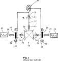
Ein bekanntes monoartikuläres Roboter-Gelenk ist schematisch in
Eine Drehung des Gelenks um das Gelenk
Das anhand
Von menschlichen Gelenken sind neben monoartikulären Gelenken und entsprechend monoartikulären Muskeln auch sogenannte biartikuläre Muskeln bekannt. Biartikuläre Muskeln bewegen zwei Gelenke. Ein Beispiel hierfür ist der Bizeps und der Trizeps im Oberarm des Menschen. Durch biartikuläre Muskeln kann die Stabilität bei äußeren unvorhersehbaren Störungen, sogenannten Perturbationen verbessert werden. Ferner ist es durch biartikuläre Muskeln möglich, Energie von einem Gelenk in das andere zu übertragen. Des Weiteren sind biartikuläre Muskeln beim Menschen maßgeblich an der Variierung von Größe und Ausrichtung der sogenannten Steifigkeitsellipse beteiligt. Durch derartige biartikuläre Muskeln ist der Mensch fähig, diese Steifigkeitsellipse bezüglich der Ausprägung externer Perturbationen in ihrer Größe, Form und Orientierung entsprechend anzupassen. Diese Zusammenhänge sind insbesondere beschrieben in:
- – Franklin DW. Burdet E. Osu R, Kawato M. Milner TE (2003): "Functional significance of stiffness in adaption of multijoint arm movements in stable and unstable environments"; Exp Brain Res 151: 145–157;
- – Franklin, D. W., Liaw, G., Milner, T. E., Osu, R., Burdet, E., and Kawato, M. (2007), "Endpoint stiffness of the arm is directionally tuned to instability in the environment."; Journal of Neuroscience, 27(29), 7705–7716, 0270–6474; und
- – A. V. Voronov (2004), "The roles of Monoarticular and Biarticular Muscles of the Lower Limbs in Terrestrial Locomotion", Journal of Human Physiology, Vol. 30, No. 4, 2004, pp. 476–484.
- - Franklin DW. Burdet E. Osu R, Kawato M. Milner TE (2003): "Functional significance of stiffness in adaption of multi-joint arm movements in stable and unstable environments"; Exp Brain Res 151: 145-157;
- - Franklin, DW, Liaw, G., Milner, TE, Osu, R., Burdet, E., and Kawato, M. (2007), "Endpoint stiffness of the arm is directionally tuned to instability in the environment."; Journal of Neuroscience, 27 (29), 7705-7716, 0270-6474; and
- AV Voronov (2004), The roles of Monoarticular and Biological Muscles of the Lower Limbs in Terrestrial Locomotion, Journal of Human Physiology, Vol. 4, 2004, pp. 476-484.
Aufgabe der Erfindung ist es, ein Roboter-Gelenksystem zu schaffen, das auf einfache Weise eine variable Steifigkeit aufweist, wobei vorzugsweise zwischen zwei Gelenken Energie übertragen werden kann. The object of the invention is to provide a robot joint system which has a variable stiffness in a simple manner, wherein preferably between two joints energy can be transmitted.
Die Lösung der Aufgabe erfolgt erfindungsgemäß durch ein Roboter-Gelenksystem gemäß Anspruch 1. The object is achieved according to the invention by a robot joint system according to claim 1.
Das erfindungsgemäße Roboter-Gelenksystem weist zwei Gelenkeinrichtungen auf. Jede der Gelenkeinrichtungen weist ein Gelenk auf, das über eine Antriebswelle mit einer Getriebeeinrichtung verbunden ist. Ferner weist jede Gelenkeinrichtung zwei Antriebsmotoren auf, die mit der Getriebeeinrichtung verbunden sind. Zwischen den beiden Antriebsmotoren und der Getriebeeinrichtung ist jeweils ein Untersetzungsgetriebe angeordnet. Ferner weist jede Gelenkeinrichtung eine Energiespeichereinrichtung auf, die jeweils mit einem der beiden Untersetzungsgetriebe verbunden ist. The robot joint system according to the invention has two joint devices. Each of the hinge devices has a joint, which is connected via a drive shaft with a transmission device. Furthermore, each hinge device has two drive motors, which are connected to the transmission device. Between the two drive motors and the transmission device, a reduction gear is arranged in each case. Furthermore, each hinge device has an energy storage device, which is connected in each case with one of the two reduction gear.
Zur erfindungsgemäßen Ausbildung einer Grundform eines biartikulären Roboter-Gelenksystems sind die beiden Gelenkeinrichtungen über eine Zusatz-Energiespeichereinrichtung miteinander verbunden. Durch das Vorsehen der Zusatz-Energiespeichereinrichtung zwischen den beiden Gelenkeinrichtungen kann eine Energieübertragung von einer Gelenkeinrichtung auf die andere und somit von einem Gelenk auf das andere erfolgen. Zusätzlich kann jede Gelenkeinrichtung aufgrund der jeweils vorgesehenen Energiespeichereinrichtung entsprechend eines monoartikulären Gelenks Energie speichern. To form a basic form of a bi-articulated robot joint system according to the invention, the two joint devices are connected to one another via an additional energy storage device. By providing the additional energy storage device between the two hinge devices, an energy transfer from one hinge device to the other and thus from one hinge to the other can take place. In addition, each joint device can store energy due to the respectively provided energy storage device corresponding to a monoarticular joint.
Vorzugsweise ist die Zusatz-Energiespeichereinrichtung derart ausgebildet, dass sie einen ersten Energiespeicher aufweist, der zwischen der Antriebswelle eines der beiden Gelenke und einem Untersetzungsgetriebe der anderen Gelenkeinrichtung angeordnet ist. Dem ersten Energiespeicher kann somit von der Antriebswelle Energie zugeführt werden. Eine weitere Zufuhr zu dem ersten Energiespeicher kann über das Untersetzungsgetriebe der anderen Gelenkeinrichtung erfolgen. Entsprechend kann von dem ersten Energiespeicher Energie an die Antriebswelle oder das Untersetzungsgetriebe abgegeben werden. Preferably, the additional energy storage device is designed such that it has a first energy storage, which is arranged between the drive shaft of one of the two joints and a reduction gear of the other joint device. The first energy store can thus be supplied by the drive shaft energy. A further supply to the first energy store can take place via the reduction gear of the other joint device. Accordingly, energy can be output from the first energy store to the drive shaft or the reduction gear.
Besonders bevorzugt ist es, dass die Zusatz-Energiespeichereinrichtung zusätzlich einen zweiten Energiespeicher aufweist. Dieser ist entsprechend dem ersten Energiespeicher zwischen der Antriebswelle der einen Getriebeeinrichtung und einem Untersetzungsgetriebe der anderen Getriebeeinrichtung angeordnet. Hierbei sind die beiden Energiespeicher vorzugsweise derart angeordnet, dass jeder Energiespeicher mit unterschiedlichen Antriebswellen sowie mit unterschiedlichen Untersetzungsgetrieben verbunden ist. Durch eine derartige Anordnung ist es möglich, dass zwischen beiden Gelenkeinrichtungen sowohl über die Antriebswelle der Gelenke als auch über die vorgesehenen Übersetzungsgetriebe Energie auf die andere Gelenkeinrichtung übertragen wird. It is particularly preferred that the additional energy storage device additionally has a second energy store. This is arranged according to the first energy storage between the drive shaft of a transmission device and a reduction gear of the other transmission device. Here, the two energy storage are preferably arranged such that each energy storage is connected to different drive shafts and with different reduction gears. Such an arrangement makes it possible for energy to be transmitted to the other joint device between the two joint devices both via the drive shaft of the joints and via the intended transmission gear.
Selbst bei einer möglichst großen Flexibilität, insbesondere hinsichtlich der Einstellbarkeit der Steifigkeit ist es des Weiteren bevorzugt, dass die beiden Energiespeichereinrichtungen je Gelenkeinrichtung mit einem anderen Untersetzungsgetriebe verbunden sind als der erste und/ oder der zweite Energiespeicher der Zusatz-Energiespeichereinrichtung. In besonders bevorzugter Ausführungsform weist jede Gelenkeinrichtung zwei Untersetzungsgetriebe auf, wobei mit jedem der insgesamt vier Untersetzungsgetriebe entweder eine gelenkspezifische Energiespeichereinrichtung oder eine der beiden Energiespeicher der Zusatz-Energiespeichereinrichtung verbunden sind. Bei einer weiteren besonders bevorzugten Ausführungsform ist zur Verbesserung der Bewegungsmöglichkeit der einzelnen Gelenke zumindest bei einer, insbesondere bei beiden Getriebeeinrichtungen, ein dritter Antriebsmotor vorgesehen, der vorzugsweise mit der Getriebeeinrichtung verbunden ist. Even with the greatest possible flexibility, in particular with regard to the adjustability of the rigidity, it is furthermore preferred for the two energy storage devices per joint device to be connected to a different reduction gearbox than the first and / or the second energy store of the additional energy storage device. In a particularly preferred embodiment, each joint device has two reduction gears, with each of the four reduction gears either a joint-specific energy storage device or one of the two energy storage of the additional energy storage device are connected. In a further particularly preferred embodiment, a third drive motor is provided to improve the possibility of movement of the individual joints at least one, in particular in both transmission devices, which is preferably connected to the transmission device.
Des Weiteren ist es hierbei bevorzugt, dass zwischen dem dritten Antriebsmotor und der Getriebeeinrichtung ein drittes Untersetzungsgetriebe angeordnet ist. Durch Zwischenschalten des dritten Untersetzungsgetriebes ist es möglich, dieses mit einer Energiespeichereinrichtung, insbesondere der bereits je Gelenkeinrichtung vorgesehenen Energiespeichereinrichtung zu verbinden. Die gelenkinterne Energiespeichereinrichtung ist somit in besonders bevorzugter Ausführungsform mit zwei der insgesamt drei vorgesehenen Untersetzungsgetriebe verbunden. Furthermore, it is preferred in this case that between the third drive motor and the transmission device, a third reduction gear is arranged. By interposing the third reduction gear, it is possible to connect it to an energy storage device, in particular the already provided for each hinge device energy storage device. The joint-internal energy storage device is thus connected in a particularly preferred embodiment with two of the total three provided reduction gear.
Vorzugsweise ist die Getriebeeinrichtung als Kegelradgetriebe ausgebildet. Hierbei ist eines der Kegelräder insbesondere unmittelbar mit der Antriebswelle des Gelenks verbunden. Bei der Ausgestaltung einer Gelenkeinrichtung mit zwei Motoren ist es bevorzugt, dass jeweils einer der beiden Motoren unter Zwischenschaltung des Untersetzungsgetriebes mit jeweils einem weiteren Kegelrad verbunden ist. Bei der Weiterbildung der Erfindung mit einem dritten Motor, bei zumindest einer der beiden Gelenkeinrichtungen ist dieser mit einem vierten Kegelrad des Kegelradgetriebes verbunden. Die Verwendung eines Kegelradgetriebes hat insbesondere den Vorteil, dass auf einfache Weise eine Verbindung mit bis zu vier Wellen möglich ist.Preferably, the transmission device is designed as a bevel gear. Here, one of the bevel gears is in particular directly connected to the drive shaft of the joint. In the embodiment of a joint device with two motors, it is preferred that each one of the two motors is connected with the interposition of the reduction gear, each with a further bevel gear. In the development of the invention with a third motor, in at least one of the two hinge devices this is connected to a fourth bevel gear of the bevel gear. The use of a bevel gear has the particular advantage that a connection with up to four waves is possible in a simple manner.
Bei den verwendeten Untersetzungsgetrieben kann es sich beispielsweise um Zykloidengetriebe handeln. Diese weisen einen guten Wirkungsgrad und einen geringen Bauraum auf. Allerdings weisen Zykloidengetriebe eine große Anzahl an bewegten Teilen und hierdurch hervorgerufenes vergleichsweise größeres Spiel auf. Bevorzugt ist daher die Verwendung von Harmoic-Drive-Getrieben. Selbstverständlich kann auch nur ein Teil der Untersetzungsgetriebe als Harmonic-Drive-Getriebe oder Zykloidengetriebe ausgebildet sein. The reduction gears used may be, for example, cycloidal gears. These have a good one Efficiency and a small installation space. However, cycloidal transmissions have a large number of moving parts and the resulting relatively larger clearance. Preference is therefore given to the use of Harmoic drive gears. Of course, only a part of the reduction gear can be designed as a harmonic drive gear or cycloidal gear.
Bei Verwendung von Harmonic-Drive-Getrieben ist es bevorzugt, dass der äußere Circular Spline drehbar gelagert ist. Des Weiteren ist der Circular Spline vorzugsweise, je nach dem in welchem Bereich des Roboter-Gelenksystem das Getriebe angeordnet ist, mit der Energiespeichereinrichtung und/ oder der Zusatz-Energiespeichereinrichtung und/ oder dem ersten und/ oder zweiten Energiespeicher verbunden. When using harmonic drive gears, it is preferred that the outer circular spline is rotatably mounted. Furthermore, the circular spline is preferably connected to the energy storage device and / or the additional energy storage device and / or the first and / or second energy store, depending on which region of the robot joint system the transmission is arranged in.
Als Energiespeichereinrichtung sind insbesondere mechanische Energiespeichereinrichtungen bevorzugt. Diese können beispielsweise als Kombination einer linearen Feder mit einer Kurvenscheibe ausgebildet sein. Besonders bevorzugt ist die Verwendung nicht linearer Federn als Energiespeichereinrichtung. As energy storage device mechanical energy storage devices are particularly preferred. These may be formed, for example, as a combination of a linear spring with a cam. Particularly preferred is the use of non-linear springs as energy storage device.
Nachfolgend wird die Erfindung anhand bevorzugter Ausführungsformen unter Bezugnahme auf die anliegenden Zeichnungen näher erläutert.The invention will be explained in more detail below with reference to preferred embodiments with reference to the accompanying drawings.
Es zeigen:Show it:
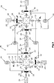
Bei der ersten in
Zur Ausgestaltung eines biartikulären Roboter-Gelenksystems ist eine Zusatz-Energiespeichereinrichtung vorgesehen, die im dargestellten Ausführungsbeispiel einen ersten Energiespeicher
Soll beispielsweise ein Drehwinkel φ1, des in
Soll hingegen nur die Steifigkeit des Roboter-Gelenksystems verändert werden, müssen die mit "Motor 3" und "Motor 6" bezeichneten Motoren
Bei dem in
Die in
Entsprechendes gilt selbstverständlich bezogen auf die in
Die in
Sofern nur die Steifigkeit der monoartikulären Feder des in
Selbstverständlich sind verschiedene Kombinationen der vorstehend beschriebenen Einzelbewegungen der Motoren mit entsprechendem Einfluss auf die mono- und biartikuläre Steifigkeit sowie die Position der Gelenke möglich. Of course, various combinations of the above-described individual movements of the motors with a corresponding influence on the mono- and bi-articular stiffness and the position of the joints are possible.
Claims (10)
Priority Applications (1)
| Application Number | Priority Date | Filing Date | Title |
|---|---|---|---|
| DE201210214094 DE102012214094B3 (en) | 2012-08-08 | 2012-08-08 | Robot joint system has drive motors that are connected to transmission device through reduction gear which is connected with energy storage device |
Applications Claiming Priority (1)
| Application Number | Priority Date | Filing Date | Title |
|---|---|---|---|
| DE201210214094 DE102012214094B3 (en) | 2012-08-08 | 2012-08-08 | Robot joint system has drive motors that are connected to transmission device through reduction gear which is connected with energy storage device |
Publications (1)
| Publication Number | Publication Date |
|---|---|
| DE102012214094B3 true DE102012214094B3 (en) | 2013-08-14 |
Family
ID=48868495
Family Applications (1)
| Application Number | Title | Priority Date | Filing Date |
|---|---|---|---|
| DE201210214094 Expired - Fee Related DE102012214094B3 (en) | 2012-08-08 | 2012-08-08 | Robot joint system has drive motors that are connected to transmission device through reduction gear which is connected with energy storage device |
Country Status (1)
| Country | Link |
|---|---|
| DE (1) | DE102012214094B3 (en) |
Cited By (3)
| Publication number | Priority date | Publication date | Assignee | Title |
|---|---|---|---|---|
| CN106182067A (en) * | 2016-07-11 | 2016-12-07 | 中国矿业大学 | A kind of stiffness variable flexible rotational joint |
| DE102018008378A1 (en) | 2018-10-22 | 2020-04-23 | Technische Universität Chemnitz | Elastic joint |
| DE102021000619B3 (en) | 2021-01-26 | 2021-12-30 | Technische Universität Chemnitz | Non-linear elastic joint with an elastic mechanism and drives |
Citations (2)
| Publication number | Priority date | Publication date | Assignee | Title |
|---|---|---|---|---|
| DE102006016958A1 (en) * | 2006-04-11 | 2007-10-25 | Deutsches Zentrum für Luft- und Raumfahrt e.V. | Antagonistic rotating device, especially for moving robot hand elements, has force transmission unit formed in such way that both drive units can act as agonists to apply rotational moment in same direction to joint element |
| DE102009000261A1 (en) * | 2009-01-15 | 2010-07-29 | Tetra Gesellschaft für Sensorik, Robotik und Automation mbH | transmission mechanism |
-
2012
- 2012-08-08 DE DE201210214094 patent/DE102012214094B3/en not_active Expired - Fee Related
Patent Citations (2)
| Publication number | Priority date | Publication date | Assignee | Title |
|---|---|---|---|---|
| DE102006016958A1 (en) * | 2006-04-11 | 2007-10-25 | Deutsches Zentrum für Luft- und Raumfahrt e.V. | Antagonistic rotating device, especially for moving robot hand elements, has force transmission unit formed in such way that both drive units can act as agonists to apply rotational moment in same direction to joint element |
| DE102009000261A1 (en) * | 2009-01-15 | 2010-07-29 | Tetra Gesellschaft für Sensorik, Robotik und Automation mbH | transmission mechanism |
Cited By (7)
| Publication number | Priority date | Publication date | Assignee | Title |
|---|---|---|---|---|
| CN106182067A (en) * | 2016-07-11 | 2016-12-07 | 中国矿业大学 | A kind of stiffness variable flexible rotational joint |
| CN106182067B (en) * | 2016-07-11 | 2018-06-15 | 中国矿业大学 | A kind of stiffness variable flexible rotational joint |
| DE102018008378A1 (en) | 2018-10-22 | 2020-04-23 | Technische Universität Chemnitz | Elastic joint |
| WO2020083417A1 (en) | 2018-10-22 | 2020-04-30 | Technische Universität Chemnitz | Elastic joint |
| DE102018008378B4 (en) | 2018-10-22 | 2020-07-23 | Technische Universität Chemnitz | Elastic joint |
| DE102021000619B3 (en) | 2021-01-26 | 2021-12-30 | Technische Universität Chemnitz | Non-linear elastic joint with an elastic mechanism and drives |
| WO2022161907A1 (en) | 2021-01-26 | 2022-08-04 | Technische Universität Chemnitz | Nonlinear elastic joint with an elastic mechanism and drives |
Similar Documents
| Publication | Publication Date | Title |
|---|---|---|
| EP2595854B1 (en) | Double pinion steering gear | |
| DE112015004085B4 (en) | MULTIMODAL CLUTCH | |
| DE112013002741T5 (en) | Lower limb structure for walking robots and walking robots | |
| DE2751579A1 (en) | REMOTE CONTROL DEVICE | |
| WO2017153500A1 (en) | Robot arm | |
| DE112015004892B4 (en) | Rotary drive mechanism in a robot | |
| DE102013204672A1 (en) | Drive device for a tracked vehicle | |
| WO2015001073A1 (en) | Air flap arrangement in a radiator air inlet system for a motor vehicle | |
| DE102012214094B3 (en) | Robot joint system has drive motors that are connected to transmission device through reduction gear which is connected with energy storage device | |
| WO2013068174A1 (en) | Transmission unit | |
| EP2398698B1 (en) | Boat drive comprising a control device | |
| DE4420790B4 (en) | Actuation device for a throttle valve | |
| DE202017101450U1 (en) | Drive group for a motor vehicle | |
| DE102011082968B4 (en) | Rotary joint with variable gear ratio | |
| EP2473759B1 (en) | Reduction gear | |
| DE102017214912A1 (en) | Transmission device for a motor vehicle | |
| DE102008027407A1 (en) | Gear for the implementation of movements | |
| DE102004046649B4 (en) | Weave drive of a weaving machine | |
| DE102012209243B4 (en) | Articulated robotic system | |
| DE202007019624U1 (en) | Drive unit and the drive unit comprehensive articulated arm | |
| EP4011787B1 (en) | Articulation device and spacecraft with articulation device | |
| DE102018109279A1 (en) | Active stabilization device | |
| DE102013216411B4 (en) | Transmission for a positioning actuator | |
| DE102013018034B4 (en) | Aligning device for aligning a platform in three rotational freedoms | |
| DE102012218912A1 (en) | Gear, particularly ship gear for ship or boat, has base gear and switchable power take-off unit for ship drive or boot drive, where gear teeth on external disk support is meshed with another gear teeth on another external disk support |
Legal Events
| Date | Code | Title | Description |
|---|---|---|---|
| R012 | Request for examination validly filed | ||
| R018 | Grant decision by examination section/examining division | ||
| R020 | Patent grant now final |
Effective date: 20131115 |
|
| R119 | Application deemed withdrawn, or ip right lapsed, due to non-payment of renewal fee |