DE102012206720A1 - Machine for harvesting stalk-like plants with an impactor arranged below a cutting disc for fibring the stubble - Google Patents
Machine for harvesting stalk-like plants with an impactor arranged below a cutting disc for fibring the stubble Download PDFInfo
- Publication number
- DE102012206720A1 DE102012206720A1 DE102012206720A DE102012206720A DE102012206720A1 DE 102012206720 A1 DE102012206720 A1 DE 102012206720A1 DE 102012206720 A DE102012206720 A DE 102012206720A DE 102012206720 A DE102012206720 A DE 102012206720A DE 102012206720 A1 DE102012206720 A1 DE 102012206720A1
- Authority
- DE
- Germany
- Prior art keywords
- cutting disc
- machine
- plants
- stubble
- impactor
- Prior art date
- Legal status (The legal status is an assumption and is not a legal conclusion. Google has not performed a legal analysis and makes no representation as to the accuracy of the status listed.)
- Pending
Links
Images


Classifications
-
- A—HUMAN NECESSITIES
- A01—AGRICULTURE; FORESTRY; ANIMAL HUSBANDRY; HUNTING; TRAPPING; FISHING
- A01D—HARVESTING; MOWING
- A01D43/00—Mowers combined with apparatus performing additional operations while mowing
- A01D43/08—Mowers combined with apparatus performing additional operations while mowing with means for cutting up the mown crop, e.g. forage harvesters
- A01D43/081—Mowers combined with apparatus performing additional operations while mowing with means for cutting up the mown crop, e.g. forage harvesters specially adapted for ensilage of maize
- A01D43/082—Gathering units
-
- A—HUMAN NECESSITIES
- A01—AGRICULTURE; FORESTRY; ANIMAL HUSBANDRY; HUNTING; TRAPPING; FISHING
- A01D—HARVESTING; MOWING
- A01D34/00—Mowers; Mowing apparatus of harvesters
- A01D34/835—Mowers; Mowing apparatus of harvesters specially adapted for particular purposes
- A01D34/8355—Mowers; Mowing apparatus of harvesters specially adapted for particular purposes for cutting up or crushing remaining standing stalks, e.g. stubble
Abstract
Eine Maschine (10) zur Ernte stängelartiger Pflanzen (58) umfasst eine Mäh- und Einzugseinrichtung (14–21), die eine untere Schneidscheibe (24) zum Abschneiden von Pflanzenstängeln von im Erdboden verbleibenden Stoppeln (60) und über der Schneidscheibe (24) übereinander angeordnete Förderelemente (28) mit um ihren Umfang verteilten Aussparungen (26) zur Aufnahme und Förderung der Pflanzenstängel aufweisen. Unterhalb der Schneidscheibe (24) ist ein in Drehung versetzbarer Schlagkörper (48, 48‘) angeordnet, dessen vorlaufende Fläche in axialer Richtung und/oder in der Umfangsrichtung der Schneidscheibe(24) konvex abgerundet ist.A machine (10) for harvesting stalk-like plants (58) comprises a mowing and collecting device (14-21) comprising a lower cutting disc (24) for cutting plant stems from stubble (60) remaining in the ground and above the cutting disc (24). have arranged one above the other conveying elements (28) distributed around its circumference recesses (26) for receiving and conveying the plant stems. Below the cutting disc (24) a rotatable impactor (48, 48 ') is arranged, the leading surface in the axial direction and / or in the circumferential direction of the cutting disc (24) is convex rounded.
Description
Die Erfindung betrifft eine Maschine zur Ernte stängelartiger Pflanzen mit einer oder mehreren seitlich nebeneinander angeordneten Mäh- und Einzugseinrichtungen, die jeweils eine untere Schneidscheibe zum Abschneiden von Pflanzenstängeln von im Erdboden verbleibenden Stoppeln und über der Schneidscheibe übereinander angeordnete Förderelemente mit um ihren Umfang verteilten Aussparungen zur Aufnahme und Förderung der Pflanzenstängel umfassen, wobei unterhalb der Schneidscheibe ein in Drehung versetzbarer Schlagkörper mit einer stumpfen vorlaufenden Fläche angeordnet ist.The invention relates to a machine for harvesting stalk-like plants with one or more laterally juxtaposed mowing and collection devices, each having a lower cutting disc for cutting plant stems remaining in the ground stubble and on the cutting disc superimposed conveyor elements distributed around its circumference recesses for receiving and promoting plant stems, wherein below the cutting disc a rotatable impactor is arranged with a blunt leading surface.
Stand der TechnikState of the art
Maschinen eingangs genannter Art dienen in der Landwirtschaft in erster Linie zum Ernten von Maispflanzen. Die Pflanzen werden durch rotierende, untere Messer abgeschnitten, in Aussparungen koaxial über den Messern angebrachter Förderscheiben aufgenommen und schließlich in den Einzugskanal eines Feldhäckslers verbracht. Der Feldhäcksler ist mit einer Häckseltrommel zum Zerkleinern der Pflanzen und einem Auswurfkrümmer versehen, durch den die gehäckselten Pflanzen auf ein Transportfahrzeug verbracht werden. Die gehäckselten Pflanzen werden üblicherweise als Futter für Tiere oder zur Biogaserzeugung verwendet. Machines of the type mentioned above are used in agriculture primarily for harvesting maize plants. The plants are cut off by rotating, lower knives, taken in recesses coaxially over the knives attached conveyor discs and finally spent in the feeder channel of a forage harvester. The forage harvester is provided with a chopper drum for shredding the plants and a chute through which the shredded plants are placed on a transport vehicle. The chopped plants are commonly used as feed for animals or for biogas production.
Nach der Ernte verbleiben noch Stoppeln der Pflanzen im Erdboden. Diese Stoppeln dienen den Raupen des gefürchteten Maiszünslers (Ostrinia nubilalis) als Überwinterungsraum. Die Raupen verpuppen sich im Frühling und fliegen bald danach als Schmetterlinge aus, um ihre Eier an den Blattunterseiten der Maispflanzen abzulegen. Nach dem Schlüpfen frisst sich die neue Generation der Raupen in die Stängel der Pflanzen, wo sie gegen Fressfeinde und Insektizide geschützt sind, und bis in die Stoppeln, woraufhin der Zyklus von neuem beginnt. Die Pflanzen werden durch die Maiszünsler schwer geschädigt, sodass der Landwirt hohe Ernteverluste erleidet.After harvest still stubble of plants remain in the ground. These stubble are the caterpillars of the dreaded European corn borer (Ostrinia nubilalis) as a wintering room. The caterpillars mate in the spring and fly out soon thereafter as butterflies to lay their eggs on the undersides of the corn plants. After hatching, the new generation of caterpillars eat into the stems of the plants, where they are protected against predators and insecticides, and into the stubble, whereupon the cycle begins again. The plants are severely damaged by the European corn borers, so that the farmer suffers high harvest losses.
Es wurde bereits vorgeschlagen, Erntevorsätze mit einer durch Lenker unmittelbar über dem Erdboden geführten Einrichtung auszustatten, welche die Pflanzenstoppeln dicht über dem Boden abschneidet und oberen Stängelteile auf eine Länge von maximal 5 cm zerkleinert oder zerfasert, um den Überwinterungsraum des Maiszünslers zu zerstören (
Weiterhin wird in der
Schließlich ist es bekannt, unterhalb der Schneidscheibe quaderförmige Räumer anzubringen, die sich näherungsweise in Umfangsrichtung erstrecken und dazu dienen, Erntegutreste von unterhalb der Schneidscheibe angeordneten Halterungen abzufördern, vgl. die als gattungsbildend angesehene
Aufgabe der ErfindungObject of the invention
Bei der Anordnung nach
Die der Erfindung zu Grunde liegende Aufgabe wird darin gesehen, eine Maschine zur Ernte stängelartiger Pflanzen mit Mäh- und Einzugseinrichtungen bereitzustellen, die bereits bei der Ernte eine hinreichende Beeinträchtigung des Überwinterungsraums des Maiszünslers in den Stoppeln der Maispflanzen ermöglicht.The object underlying the invention is seen to provide a machine for harvesting stalk-like plants with mowing and collection facilities, which allows a sufficient impairment of the Überwinterungsraums of Maiszünslers in the stubble of corn plants already at harvest.
Lösungsolution
Diese Aufgabe wird erfindungsgemäß durch die Lehre des Patentanspruchs 1 gelöst, wobei in den weiteren Patentansprüchen Merkmale aufgeführt sind, die die Lösung in vorteilhafter Weise weiterentwickeln.This object is achieved by the teaching of claim 1, wherein in the other claims features are listed, which further develop the solution in an advantageous manner.
Eine Maschine zur Ernte stängelartiger Pflanzen umfasst eine oder mehrere, bezüglich einer Vorwärtsrichtung seitlich nebeneinander angeordnete Mäh- und Einzugseinrichtung(en), die jeweils eine untere, durch einen Antrieb in Drehung versetzbare oder stationäre Schneidscheibe zum Abschneiden von Pflanzenstängeln von im Erdboden verbleibenden Stoppeln und koaxial über der Schneidscheibe übereinander angeordnete Förderelemente mit um ihren Umfang verteilten Aussparungen zur Aufnahme und Förderung der Pflanzenstängel aufweisen. Unterhalb jeder Schneidscheibe ist ein (mit gleicher, höherer oder niedrigerer Drehzahl als eine rotierende Schneidscheibe und dazu gleich- oder gegensinnig) in Drehung versetzbarer Schlagkörper mit einer stumpfen vorlaufenden Fläche angeordnet, dessen in Drehrichtung vorlaufende Fläche in axialer Richtung der Schneidscheibe und/oder in der Umfangsrichtung der Schneidscheibe konvex abgerundet ist.A stalk-like plant harvesting machine comprises one or more laterally juxtaposed mowing and gathering devices (s), each comprising a lower, rotatable by a drive or stationary cutting disc for cutting plant stalks remaining in the ground stubble and coaxial on the cutting disc superimposed conveyor elements with have their periphery distributed recesses for receiving and promoting the plant stems. Below each cutting disc is arranged (with the same, higher or lower speed than a rotating cutting disc and the same or in opposite directions) in rotation displaceable impactor with a blunt leading surface, the direction of rotation leading surface in the axial direction of the cutting disc and / or in the Circumferential direction of the cutting disc is convex rounded.
Mit anderen Worten ist unterhalb der Schneidscheibe ein Schlagkörper befestigt, der sich im Betrieb dreht und dessen vorlaufende Fläche in axialer Richtung der Schneidscheibe und/oder in der Drehrichtung der Schneidscheibe abgerundet ist und somit eine konvexe, vorlaufende Fläche bildet. Die Stoppeln der Pflanzen werden durch den abgerundeten Schlagkörper, der aufgrund seiner abgerundeten Form keine Schneidwirkung hat, nicht zerschnitten, sondern durch den stumpfen Aufprall gründlich, und bei hinreichend niedriger Arbeitshöhe bis zum Erdboden hin zerfasert. Auf diese Weise wird der Überwinterungsraum des Maiszünslers zerstört und zusätzlich wird die Rotte der Stoppeln gefördert, was dem Maiszünsler im Frühjahr die Nahrungsquelle nimmt. Die Zerfaserungswirkung der Schlagkörper reicht umso tiefer und ist somit umso erfolgreicher bei der Zerstörung des Überwintersraums der Maiszünsler, je niedriger der Schlagkörper über den Boden geführt wird.In other words, below the cutting disc a striking body is fixed, which rotates in operation and whose leading surface is rounded in the axial direction of the cutting disc and / or in the direction of rotation of the cutting disc and thus forms a convex, leading surface. The stubble of the plants are not cut by the rounded impact body, which has no cutting action due to its rounded shape, but by the blunt impact thoroughly, and at a sufficiently low working height to the ground fibered. In this way, the overwintering area of the European corn borer is destroyed and in addition the rotting of the stubble is promoted, which deprives the corn borer of the source of food in the spring. The shredding effect of the impactors is all the deeper and thus more successful in destroying the wintering habitat of the European corn borers, the lower the impactor is passed over the ground.
Der Querschnitt des Schlagkörpers ist insbesondere kreisförmig oder halbkreisförmig, wobei im zweiten Fall der Halbkreis in Drehrichtung vorläuft.The cross section of the impactor is in particular circular or semicircular, wherein in the second case, the semicircle leads in the direction of rotation.
Vorzugsweise sind mehrere Schlagkörper äquidistant um ihre Drehachse verteilt.Preferably, several impactors are distributed equidistantly about their axis of rotation.
Schließlich wird vorgeschlagen, den Schlagkörper am Außenumfang eines sich koaxial zur Drehachse der Schneidscheibe erstreckenden Ringes anzubringen, der mit einem Flansch verbunden ist, an dem Segmente der durch einen Antrieb in Drehung versetzbaren Schneidscheibe befestigt sind. Der Schlagkörper ist demnach starr mit der Schneidscheibe gekoppelt, was den Vorteil hat, dass – ggf. mit Ausnahme von einer erforderlich werdenden Verstärkung des Flanschs und/oder der Antriebsverbindung des Flanschs zum ihn in Drehung versetzenden Getriebe gegenüber bisherigen Maschinen – keine weiteren Änderungen an der Maschine erforderlich sind und keine zusätzlichen Elemente benötigt werden, die den Bauraum und den Aufwand vergrößern würden. Bei einer anderen Ausführungsform kann dem Schneidkörper bzw. dem Ring ein von einem Drehantrieb der Schneidscheibe separater Drehantrieb zugeordnet werden, der ihn mit geeigneter Drehzahl in Drehung versetzt. Insbesondere (aber nicht nur) bei einer derartigen Ausführungsform besteht auch die Möglichkeit, den Schlagkörper unabhängig von der Maschine über den Boden zu führen, um die Stoppeln in einer hinreichend niedrigen Höhe über dem Boden zu bearbeiten (vgl.
Ausführungsbeispieleembodiments
In den Zeichnungen sind zwei nachfolgend näher beschriebene Ausführungsbeispiele der Erfindung dargestellt. Es zeigt:In the drawings, two embodiments of the invention described in more detail below are shown. It shows:
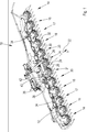
An einem Rahmen
Zwischen den Mäh- und Einzugseinrichtungen
Beim Erntebetrieb werden die Mäh- und Einzugseinrichtungen
An der Rückseite des Rahmens
Die
Die
Die
Die im Erdboden verbleibenden Stoppeln
Bei bisher üblichen, relativ scharfkantigen Schlagkörpern findet nur ein geringfügiges Zerspleissen der Stoppeln
ZITATE ENTHALTEN IN DER BESCHREIBUNG QUOTES INCLUDE IN THE DESCRIPTION
Diese Liste der vom Anmelder aufgeführten Dokumente wurde automatisiert erzeugt und ist ausschließlich zur besseren Information des Lesers aufgenommen. Die Liste ist nicht Bestandteil der deutschen Patent- bzw. Gebrauchsmusteranmeldung. Das DPMA übernimmt keinerlei Haftung für etwaige Fehler oder Auslassungen.This list of the documents listed by the applicant has been generated automatically and is included solely for the better information of the reader. The list is not part of the German patent or utility model application. The DPMA assumes no liability for any errors or omissions.
Zitierte PatentliteraturCited patent literature
- DE 102004020447 A1 [0004] DE 102004020447 A1 [0004]
- DE 3713025 A1 [0005, 0007] DE 3713025 A1 [0005, 0007]
- DE 102007035791 B3 [0006, 0007] DE 102007035791 B3 [0006, 0007]
- DE 102004020477 A1 [0007, 0014] DE 102004020477 A1 [0007, 0014]
Claims (4)
Priority Applications (2)
| Application Number | Priority Date | Filing Date | Title |
|---|---|---|---|
| DE102012206720A DE102012206720A1 (en) | 2012-04-24 | 2012-04-24 | Machine for harvesting stalk-like plants with an impactor arranged below a cutting disc for fibring the stubble |
| EP13159971.4A EP2656724B1 (en) | 2012-04-24 | 2013-03-19 | Machine for harvesting stalk-like plants with an impact body for fraying stubble to be arranged below a circular saw blade |
Applications Claiming Priority (1)
| Application Number | Priority Date | Filing Date | Title |
|---|---|---|---|
| DE102012206720A DE102012206720A1 (en) | 2012-04-24 | 2012-04-24 | Machine for harvesting stalk-like plants with an impactor arranged below a cutting disc for fibring the stubble |
Publications (1)
| Publication Number | Publication Date |
|---|---|
| DE102012206720A1 true DE102012206720A1 (en) | 2013-10-24 |
Family
ID=48082843
Family Applications (1)
| Application Number | Title | Priority Date | Filing Date |
|---|---|---|---|
| DE102012206720A Pending DE102012206720A1 (en) | 2012-04-24 | 2012-04-24 | Machine for harvesting stalk-like plants with an impactor arranged below a cutting disc for fibring the stubble |
Country Status (2)
| Country | Link |
|---|---|
| EP (1) | EP2656724B1 (en) |
| DE (1) | DE102012206720A1 (en) |
Cited By (10)
| Publication number | Priority date | Publication date | Assignee | Title |
|---|---|---|---|---|
| DE102014219694A1 (en) | 2014-09-29 | 2016-03-31 | Maschinenfabrik Kemper Gmbh & Co. Kg | Corn harvesting machine with plant stirrer and shredder |
| DE102015206343A1 (en) | 2015-04-09 | 2016-10-13 | Maschinenfabrik Kemper Gmbh & Co. Kg | Harvesting device with telescopic cutting drum attachment |
| EP3272199A1 (en) | 2016-07-20 | 2018-01-24 | Deere & Company | Mulching device for processing plant stumps on a field |
| DE102016214321A1 (en) | 2016-08-03 | 2018-02-08 | Deere & Company | Harvest header for harvesting stalk-like plants with a tool for processing plant stubble |
| DE102016214324A1 (en) | 2016-08-03 | 2018-02-08 | Deere & Company | Harvest header with a mulcher for processing stumps of plants on a field |
| DE102016214317A1 (en) | 2016-08-03 | 2018-02-08 | Deere & Company | Mulching device for processing plant stumps standing on a field |
| DE102016214323A1 (en) | 2016-08-03 | 2018-02-08 | Deere & Company | Mulching device for mechanical processing of plant stubble |
| US20180242524A1 (en) * | 2015-09-08 | 2018-08-30 | Carl Geringhoff Gmbh & Co. Kg | Device for Harvesting Stalk Material |
| DE102016208511B4 (en) | 2015-05-27 | 2021-08-26 | Maschinenfabrik Kemper Gmbh & Co. Kg | Machine for harvesting stem-like plants with a blade arrangement for breaking up the stubble |
| DE102022107609A1 (en) | 2022-03-30 | 2023-10-05 | Claas Saulgau Gmbh | Feed rotor of a corn header, corn header and method for producing the feed rotor |
Families Citing this family (4)
| Publication number | Priority date | Publication date | Assignee | Title |
|---|---|---|---|---|
| CN109005893A (en) * | 2018-08-20 | 2018-12-18 | 北海飞九天电子科技有限公司 | A kind of automatic new fresh and tender maize peeling machine |
| DE202018107424U1 (en) * | 2018-12-24 | 2019-02-14 | Klaus Wallner | cutting blade |
| CN111386842A (en) * | 2020-03-20 | 2020-07-10 | 石家庄美迪机械有限公司 | Straw harvesting device |
| CN116034722B (en) * | 2023-01-09 | 2023-09-19 | 淮安生物工程高等职业学校 | Corn stalk harvester treatment equipment |
Citations (4)
| Publication number | Priority date | Publication date | Assignee | Title |
|---|---|---|---|---|
| DE3713025A1 (en) | 1987-04-16 | 1988-10-27 | Claas Saulgau Gmbh | Method and apparatus for the harvesting of coarse-stemmed crop, for example of maize |
| DE102004020477A1 (en) | 2004-04-26 | 2005-11-17 | Rivo Mahefa, Ramarolahy Andriatiaray | Internal four stroke combustion engine has piston connected to engine shaft swinging within two hoods, whose movement synchronized with valve opening/shutting enables four strokes to complete a Beau de Rochas working cycle |
| DE102004020447A1 (en) | 2004-04-27 | 2005-12-01 | Maschinenfabrik Bernard Krone Gmbh | Corroding pest or diseased mushroom distribution method, involves carrying out mechanical milling of plant stubbles and/or harvested crop by cutting and milling device before plant stubbles are transferred from wheels of harvesting machine |
| DE102007035791B3 (en) | 2007-07-31 | 2009-03-26 | Maschinenfabrik Kemper Gmbh & Co. Kg | Mowing and collecting device for stalk-like plants harvesting machine, has holder with straight edge that together with scraper closes narrow gap such that undesired accumulation of residues of harvested plant are removed by scraper |
Family Cites Families (3)
| Publication number | Priority date | Publication date | Assignee | Title |
|---|---|---|---|---|
| DE102005055621B3 (en) * | 2005-11-22 | 2007-04-26 | Maschinenfabrik Kemper Gmbh & Co. Kg | Machine to harvest plants with stalks has rotatable cutting disc to cut plants, conveyor disc above it with notches to collect stalks and raker under cutting disc connected on floating axle parallel to turning axis of cutting disc |
| DE102006051619A1 (en) * | 2006-11-02 | 2008-05-21 | Maschinenfabrik Kemper Gmbh & Co. Kg | Cutting disc for e.g. maize, harvesting machine, has body with teeth provided with breaking points, at which outer sections of teeth is separable, where teeth remain with new, sharp cutting edges after separation of outer sections |
| US8171707B2 (en) * | 2010-01-25 | 2012-05-08 | Kitchel Enterprises, Llc | Corn stalk rollers |
-
2012
- 2012-04-24 DE DE102012206720A patent/DE102012206720A1/en active Pending
-
2013
- 2013-03-19 EP EP13159971.4A patent/EP2656724B1/en active Active
Patent Citations (4)
| Publication number | Priority date | Publication date | Assignee | Title |
|---|---|---|---|---|
| DE3713025A1 (en) | 1987-04-16 | 1988-10-27 | Claas Saulgau Gmbh | Method and apparatus for the harvesting of coarse-stemmed crop, for example of maize |
| DE102004020477A1 (en) | 2004-04-26 | 2005-11-17 | Rivo Mahefa, Ramarolahy Andriatiaray | Internal four stroke combustion engine has piston connected to engine shaft swinging within two hoods, whose movement synchronized with valve opening/shutting enables four strokes to complete a Beau de Rochas working cycle |
| DE102004020447A1 (en) | 2004-04-27 | 2005-12-01 | Maschinenfabrik Bernard Krone Gmbh | Corroding pest or diseased mushroom distribution method, involves carrying out mechanical milling of plant stubbles and/or harvested crop by cutting and milling device before plant stubbles are transferred from wheels of harvesting machine |
| DE102007035791B3 (en) | 2007-07-31 | 2009-03-26 | Maschinenfabrik Kemper Gmbh & Co. Kg | Mowing and collecting device for stalk-like plants harvesting machine, has holder with straight edge that together with scraper closes narrow gap such that undesired accumulation of residues of harvested plant are removed by scraper |
Cited By (14)
| Publication number | Priority date | Publication date | Assignee | Title |
|---|---|---|---|---|
| EP3001892A1 (en) | 2014-09-29 | 2016-04-06 | Maschinenfabrik Kemper GmbH & Co. KG | Maize harvesting device with plant stubble puller and shredder |
| EP3001892B1 (en) | 2014-09-29 | 2017-06-14 | Maschinenfabrik Kemper GmbH & Co. KG | Maize harvesting device with plant stubble puller and shredder |
| DE102014219694A1 (en) | 2014-09-29 | 2016-03-31 | Maschinenfabrik Kemper Gmbh & Co. Kg | Corn harvesting machine with plant stirrer and shredder |
| DE102015206343A1 (en) | 2015-04-09 | 2016-10-13 | Maschinenfabrik Kemper Gmbh & Co. Kg | Harvesting device with telescopic cutting drum attachment |
| DE102016208511B4 (en) | 2015-05-27 | 2021-08-26 | Maschinenfabrik Kemper Gmbh & Co. Kg | Machine for harvesting stem-like plants with a blade arrangement for breaking up the stubble |
| US20180242524A1 (en) * | 2015-09-08 | 2018-08-30 | Carl Geringhoff Gmbh & Co. Kg | Device for Harvesting Stalk Material |
| EP3272199A1 (en) | 2016-07-20 | 2018-01-24 | Deere & Company | Mulching device for processing plant stumps on a field |
| DE102017207337A1 (en) | 2016-07-20 | 2018-01-25 | Deere & Company | Mulching device for processing plant stumps standing on a field |
| US10398080B2 (en) | 2016-07-20 | 2019-09-03 | Deere & Company | Mulching device for processing plant stubble on a field |
| DE102016214321A1 (en) | 2016-08-03 | 2018-02-08 | Deere & Company | Harvest header for harvesting stalk-like plants with a tool for processing plant stubble |
| DE102016214323A1 (en) | 2016-08-03 | 2018-02-08 | Deere & Company | Mulching device for mechanical processing of plant stubble |
| DE102016214317A1 (en) | 2016-08-03 | 2018-02-08 | Deere & Company | Mulching device for processing plant stumps standing on a field |
| DE102016214324A1 (en) | 2016-08-03 | 2018-02-08 | Deere & Company | Harvest header with a mulcher for processing stumps of plants on a field |
| DE102022107609A1 (en) | 2022-03-30 | 2023-10-05 | Claas Saulgau Gmbh | Feed rotor of a corn header, corn header and method for producing the feed rotor |
Also Published As
| Publication number | Publication date |
|---|---|
| EP2656724B1 (en) | 2019-09-25 |
| EP2656724A3 (en) | 2017-11-22 |
| EP2656724A2 (en) | 2013-10-30 |
Similar Documents
| Publication | Publication Date | Title |
|---|---|---|
| EP2656724B1 (en) | Machine for harvesting stalk-like plants with an impact body for fraying stubble to be arranged below a circular saw blade | |
| EP1106049B1 (en) | Corn gathering and picking device with a chopping device | |
| DE19734747B4 (en) | Corn harvest attachment for attachment to a self-propelled harvester | |
| EP2255610B1 (en) | Header for harvesting stalk plants | |
| EP1106048B1 (en) | Corn gathering and picking device of a crop loading device | |
| EP0824856B1 (en) | Machine for mowing and chopping maize and suchlike stalk crops | |
| DE102006001383B4 (en) | The gathering | |
| DE102017207337A1 (en) | Mulching device for processing plant stumps standing on a field | |
| DE2322136A1 (en) | SUGAR CANE HARVEST MACHINE | |
| EP3001892B1 (en) | Maize harvesting device with plant stubble puller and shredder | |
| EP1106047A1 (en) | Corn gathering and picking device and harvesting machine | |
| EP3016494B1 (en) | Agricultural implement and method for processing plant stubble | |
| DE102015206845A1 (en) | Cutting unit for whole plant harvest | |
| DE102006048659A1 (en) | Machine for harvesting stalk-like plants with a scraper and this downstream guide element | |
| DE102011000426A1 (en) | Dreschwerk of a combine harvester | |
| EP2923556B1 (en) | Front attachment for a self-propelled combine-harvester for harvesting maize | |
| DE3115723A1 (en) | Adaptor for cutting off and folding round the corn stalks and for breaking the corncobs | |
| DE102016214323A1 (en) | Mulching device for mechanical processing of plant stubble | |
| DE102016208511B4 (en) | Machine for harvesting stem-like plants with a blade arrangement for breaking up the stubble | |
| DE102007062455A1 (en) | Machine for harvesting stalk-like plants | |
| EP1129610B1 (en) | Corn gathering and picking device for a harvesting machine | |
| EP1566091B1 (en) | Harvesting device with a stem chopper | |
| DE102016214321A1 (en) | Harvest header for harvesting stalk-like plants with a tool for processing plant stubble | |
| DE2320126C2 (en) | Precision chip forage harvester - has pick up hood with stone deflector | |
| DE102016214324A1 (en) | Harvest header with a mulcher for processing stumps of plants on a field |
Legal Events
| Date | Code | Title | Description |
|---|---|---|---|
| R012 | Request for examination validly filed | ||
| R002 | Refusal decision in examination/registration proceedings | ||
| R003 | Refusal decision now final |