DE102012201631A1 - tire - Google Patents
tire Download PDFInfo
- Publication number
- DE102012201631A1 DE102012201631A1 DE102012201631A DE102012201631A DE102012201631A1 DE 102012201631 A1 DE102012201631 A1 DE 102012201631A1 DE 102012201631 A DE102012201631 A DE 102012201631A DE 102012201631 A DE102012201631 A DE 102012201631A DE 102012201631 A1 DE102012201631 A1 DE 102012201631A1
- Authority
- DE
- Germany
- Prior art keywords
- main grooves
- range
- grooves
- shoulder
- ribs
- Prior art date
- Legal status (The legal status is an assumption and is not a legal conclusion. Google has not performed a legal analysis and makes no representation as to the accuracy of the status listed.)
- Pending
Links
Images
Classifications
-
- B—PERFORMING OPERATIONS; TRANSPORTING
- B60—VEHICLES IN GENERAL
- B60C—VEHICLE TYRES; TYRE INFLATION; TYRE CHANGING; CONNECTING VALVES TO INFLATABLE ELASTIC BODIES IN GENERAL; DEVICES OR ARRANGEMENTS RELATED TO TYRES
- B60C11/00—Tyre tread bands; Tread patterns; Anti-skid inserts
- B60C11/03—Tread patterns
- B60C11/0306—Patterns comprising block rows or discontinuous ribs
-
- B—PERFORMING OPERATIONS; TRANSPORTING
- B60—VEHICLES IN GENERAL
- B60C—VEHICLE TYRES; TYRE INFLATION; TYRE CHANGING; CONNECTING VALVES TO INFLATABLE ELASTIC BODIES IN GENERAL; DEVICES OR ARRANGEMENTS RELATED TO TYRES
- B60C11/00—Tyre tread bands; Tread patterns; Anti-skid inserts
- B60C11/03—Tread patterns
- B60C2011/0337—Tread patterns characterised by particular design features of the pattern
- B60C2011/0339—Grooves
- B60C2011/0358—Lateral grooves, i.e. having an angle of 45 to 90 degees to the equatorial plane
- B60C2011/0372—Lateral grooves, i.e. having an angle of 45 to 90 degees to the equatorial plane with particular inclination angles
-
- B—PERFORMING OPERATIONS; TRANSPORTING
- B60—VEHICLES IN GENERAL
- B60C—VEHICLE TYRES; TYRE INFLATION; TYRE CHANGING; CONNECTING VALVES TO INFLATABLE ELASTIC BODIES IN GENERAL; DEVICES OR ARRANGEMENTS RELATED TO TYRES
- B60C11/00—Tyre tread bands; Tread patterns; Anti-skid inserts
- B60C11/03—Tread patterns
- B60C2011/0337—Tread patterns characterised by particular design features of the pattern
- B60C2011/0339—Grooves
- B60C2011/0381—Blind or isolated grooves
-
- B—PERFORMING OPERATIONS; TRANSPORTING
- B60—VEHICLES IN GENERAL
- B60C—VEHICLE TYRES; TYRE INFLATION; TYRE CHANGING; CONNECTING VALVES TO INFLATABLE ELASTIC BODIES IN GENERAL; DEVICES OR ARRANGEMENTS RELATED TO TYRES
- B60C11/00—Tyre tread bands; Tread patterns; Anti-skid inserts
- B60C11/03—Tread patterns
- B60C2011/0337—Tread patterns characterised by particular design features of the pattern
- B60C2011/0386—Continuous ribs
- B60C2011/0393—Narrow ribs, i.e. having a rib width of less than 8 mm
- B60C2011/0395—Narrow ribs, i.e. having a rib width of less than 8 mm for linking shoulder blocks
-
- Y—GENERAL TAGGING OF NEW TECHNOLOGICAL DEVELOPMENTS; GENERAL TAGGING OF CROSS-SECTIONAL TECHNOLOGIES SPANNING OVER SEVERAL SECTIONS OF THE IPC; TECHNICAL SUBJECTS COVERED BY FORMER USPC CROSS-REFERENCE ART COLLECTIONS [XRACs] AND DIGESTS
- Y02—TECHNOLOGIES OR APPLICATIONS FOR MITIGATION OR ADAPTATION AGAINST CLIMATE CHANGE
- Y02T—CLIMATE CHANGE MITIGATION TECHNOLOGIES RELATED TO TRANSPORTATION
- Y02T10/00—Road transport of goods or passengers
- Y02T10/80—Technologies aiming to reduce greenhouse gasses emissions common to all road transportation technologies
- Y02T10/86—Optimisation of rolling resistance, e.g. weight reduction
Abstract
Es wird ein Luftreifen bereitgestellt, durch den das Fahrgeräusch verringert werden kann, während gleichzeitig ausgezeichneter Rollwiderstand und ausgezeichnete Nassleistung beibehalten werden. Bei dem bereitgestellten Luftreifen sind in einem Laufflächenabschnitt T gebildet (a) Hauptrillen (1, 1) der Mittelseiten und Hauptrillen (2, 2) der Schulterseiten; (b) eine zentrale Rippe (10), die zwischen den Hauptrillen (1, 1) angeordnet ist; Mittelrippen (20), die zwischen Hauptrillen (1) und (2) angeordnet sind; und Schulterrippen (30), die auf den Außenseiten der Hauptrillen (2, 2) angeordnet sind. Eine Mehrzahl von Stollenrillen (11) und (21), die in den Rippen blind enden, ist in der zentralen Rippe (10) und den Mittelrippen (20) so gebildet, dass eine Rillenbreite der Stollenrillen (11) und (21) allmählich mit Nähe zu den Mittelseiten abnimmt. Eine Mehrzahl von Stollenrillen (31) ist in den Schulterrippen (30) so gebildet, dass sie nicht mit den Hauptrillen (2) verbunden ist. Ein Abstand von der Mittelposition des Laufflächenabschnitts (T) zu den Mitten der Hauptrillen (1) ist so festgelegt, dass er in einem Bereich von 15% bis 25% eines Abstands von der Mittelposition zu einem Bodenkontaktrand liegt. Ein Abstand von der Mittelposition des Laufflächenabschnitts (T) zu den Mitten der Hauptrillen (2) ist so festgelegt, dass er in einem Bereich von 60% bis 80% des Abstands von der Mittelposition zum Bodenkontaktrand liegt. Eine Breite der Hauptrillen (1) ist so festgelegt, dass sie in einem Bereich von 70% bis 90% einer Breite der Hauptrillen (2) liegt. Eine Gesamtfläche der Hauptrillen (1) und der Hauptrillen (2) ist so festgelegt, dass sie in einem Bereich von 15% bis 25% einer Fläche eines Bodenkontaktbereichs (A) des Laufflächenabschnitts (T) liegt, und ein Rillenflächenverhältnis eines Mittelbereichs (Ac) ist so konfiguriert, dass es geringer ist als ein Rillenflächenverhältnis der Schulterbereiche (As).There is provided a pneumatic tire which can reduce running noise while maintaining excellent rolling resistance and excellent wet performance. In the pneumatic tire provided, there are formed in a tread portion T (a) main grooves (1, 1) of the center sides and main grooves (2, 2) of the shoulder sides; (b) a central rib (10) disposed between the main grooves (1,1); Central ribs (20) disposed between main grooves (1) and (2); and shoulder ribs (30) arranged on the outer sides of the main grooves (2, 2). A plurality of lug grooves (11) and (21) that blindly end in the ribs are formed in the central rib (10) and the central ribs (20) so that a groove width of the lug grooves (11) and (21) gradually becomes Closeness to the middle sides. A plurality of lug grooves (31) are formed in the shoulder ribs (30) so as not to be connected to the main grooves (2). A distance from the central position of the tread portion (T) to the centers of the main grooves (1) is set to be in a range of 15% to 25% of a distance from the central position to a ground contact edge. A distance from the central position of the tread portion (T) to the centers of the main grooves (2) is set to be in a range of 60% to 80% of the distance from the central position to the ground contact edge. A width of the main grooves (1) is set to be in a range from 70% to 90% of a width of the main grooves (2). A total area of the main grooves (1) and the main grooves (2) is set to be in a range of 15% to 25% of an area of a ground contact area (A) of the tread portion (T), and a groove area ratio of a central area (Ac) is configured to be less than a groove area ratio of the shoulder portions (As).
Description
Technisches GebietTechnical area
Die vorliegende Erfindung betrifft einen Luftreifen, der mit vier Hauptrillen versehen ist, die sich in Reifenumfangsrichtung in einem Laufflächenabschnitt erstrecken, und betrifft insbesondere einen Luftreifen, bei dem das Fahrgeräusch verringert werden kann, während gleichzeitig ausgezeichneter Rollwiderstand und ausgezeichnete Nassleistung beibehalten werden.The present invention relates to a pneumatic tire provided with four main grooves extending in the tire circumferential direction in a tread portion, and more particularly, to a pneumatic tire in which the driving noise can be reduced while maintaining excellent rolling resistance and wet performance.
Stand der TechnikState of the art
Ein Geräusch, das durch Luftreifen, die an einem Fahrzeug montiert sind, wird erzeugt, wenn das Fahrzeug vorbeifährt, und dieses Geräusch wird im Allgemeinen als „Fahrgeräusch” bezeichnet. Das Fahrgeräusch wird durch einen Pumpvorgang verstärkt, der auftritt, wenn die Luft in den Rillen des Laufflächenabschnitts komprimiert und freigegeben wird. Aus diesem Grund ist das Verringern der Rillenfläche im Laufflächenabschnitt nützlich bei der Verringerung des Fahrgeräuschs. Wenn beispielsweise ein Luftreifen, in dem vier Hauptrillen bereitgestellt wurden, die sich in Reifenumfangsrichtung in einem Laufflächenabschnitt erstrecken (siehe z. B. Patentdokument 1), so konfiguriert ist, dass die Rillenfläche im Laufflächenabschnitt verringert ist, kann das Fahrgeräusch verringert werden.A noise generated by pneumatic tires mounted on a vehicle is generated when the vehicle passes by, and this noise is generally referred to as "driving noise". The driving noise is amplified by a pumping action that occurs when the air in the grooves of the tread portion is compressed and released. For this reason, reducing the groove area in the tread portion is useful in reducing the driving noise. For example, when a pneumatic tire in which four main grooves are provided that extend in the tire circumferential direction in a tread portion (see, for example, Patent Document 1) is configured so that the groove area in the tread portion is reduced, the driving noise can be reduced.
Wenn die Rillenfläche jedoch verringert ist, um das Fahrgeräusch zu verringern, besteht ein Problem dahingehend, dass sich die Abflusseigenschaften verschlechtern und die Nassleistung negativ beeinflusst wird. Außerdem besteht ein Problem, weil das Verringern der Rillenfläche zu einer Erhöhung des Kautschukvolumens im Laufflächenabschnitt führt, was zu einer negativen Beeinflussung des Rollwiderstands führt. Daher ist es schwierig, das Fahrgeräusch zu verringern, und gleichzeitig einen ausgezeichneten Rollwiderstand und ausgezeichnete Nassleistung beizubehalten, und derzeit ist es schwierig, diese beiden Eigenschaften gleichzeitig zu erfüllen.However, if the groove area is decreased to reduce the running noise, there is a problem that the drain characteristics deteriorate and the wet performance is adversely affected. In addition, there is a problem because decreasing the groove area results in an increase in the rubber volume in the tread portion, resulting in a negative influence on the rolling resistance. Therefore, it is difficult to reduce the driving noise while maintaining excellent rolling resistance and wet performance, and at present it is difficult to satisfy both of these properties at the same time.
Dokumente des Stands der TechnikDocuments of the prior art
-
Patentschrift 1:
Japanische ungeprüfte Patentanmeldung, Veröffentlichungsnr. 2006-224770 Japanese Unexamined Patent Application Publication no. 2006-224770
Zusammenfassung der ErfindungSummary of the invention
Durch die Erfindung zu lösendes Problem:Problem to be solved by the invention:
Eine Aufgabe der vorliegenden Erfindung ist das Bereitstellen eines Luftreifens, durch den das Fahrgeräusch verringert werden kann, während gleichzeitig ein ausgezeichneter Rollwiderstand und eine ausgezeichnete Nassleistung beibehalten werden.An object of the present invention is to provide a pneumatic tire by which the driving noise can be reduced while maintaining excellent rolling resistance and wet performance.
Mittel zum Lösen des Problems:Means of solving the problem:
Ein Luftreifen, der die Aufgabe der vorliegenden Erfindung erreicht, weist ein Paar erster Hauptrillen, die auf beiden Seiten einer Mittelposition positioniert sind und sich in Reifenumfangsrichtung erstrecken, auf; ein Paar zweiter Hauptrillen, die weiter zu den Schulterseiten als die ersten Hauptrillen positioniert sind und sich in Reifenumfangsrichtung erstrecken; eine zentrale Rippe, die zwischen dem Paar erster Hauptrillen angeordnet ist; Mittelrippen, die zwischen den ersten Hauptrillen und den zweiten Hauptrillen angeordnet sind, und Schulterrippen, die auf den Außenseiten der zweiten Hauptrillen in einem Laufflächenabschnitt angeordnet sind. Eine Mehrzahl von Stollenrillen, die sich von einer Wandfläche auf den Schulterseiten zu den Mittelseiten hin erstrecken und in der Rippe blind enden, wird jeweils in der zentralen Rippe und den Mittelrippen so gebildet, dass eine Rillenbreite der Stollenrillen sich allmählich mit der Nähe zu den Mittelseiten verringert. Eine Mehrzahl von Stollenrillen, die sich in Reifenbreitenrichtung erstrecken, ist so in den Schulterrippen gebildet, dass sie nicht mit den zweiten Hauptrillen verbunden sind. Ein Abstand von der Mittelposition des Laufflächenabschnitts zu den Mitten der ersten Hauptrillen ist so festgelegt, dass er in einem Bereich von 15% bis 25% eines Abstands von der Mittelposition zu einem Bodenkontaktrand liegt; und ein Abstand von der Mittelposition des Laufflächenabschnitts zu den Mitten der zweiten Hauptrillen ist so festgelegt, dass er in einem Bereich von 60% bis 80% des Abstands von der Mittelposition zum Bodenkontaktrand liegt. Eine Breite der ersten Hauptrillen ist so festgelegt, dass sie in einem Bereich von 70% bis 90% einer Breite der zweiten Hauptrillen liegt. Eine Gesamtfläche der ersten Hauptrillen und der zweiten Hauptrillen ist so festgelegt, dass sie in einem Bereich von 15% bis 25% einer Fläche eines Bodenkontaktbereichs des Laufflächenabschnitts liegt. Wenn der Bodenkontaktbereich des Laufflächenabschnitts in einen Mittelbereich und Schulterbereiche unterteilt ist, die eine Position bei 50% des Abstands von der Mittelposition des Laufflächenabschnitts zum Bodenkontaktrand als eine Begrenzung haben, ist ein Rillenflächenverhältnis des Mittelbereichs so konfiguriert, dass es weniger als ein Rillenflächenverhältnis der Schulterbereiche darstellt.A pneumatic tire achieving the object of the present invention has a pair of first main grooves positioned on both sides of a central position and extending in the tire circumferential direction; a pair of second main grooves positioned farther to the shoulder sides than the first main grooves and extending in the tire circumferential direction; a central rib disposed between the pair of first main grooves; Center ribs disposed between the first main grooves and the second main grooves, and shoulder ribs disposed on the outer sides of the second main grooves in a tread portion. A plurality of lug grooves extending from a wall surface on the shoulder sides toward the center sides and blindly ending in the rib are respectively formed in the central rib and the center ribs so that a groove width of the lug grooves gradually becomes close to the center sides reduced. A plurality of lug grooves extending in the tire width direction are formed in the shoulder ribs so as not to be connected to the second main grooves. A distance from the center position of the tread portion to the centers of the first main grooves is set to be in a range of 15% to 25% of a distance from the center position to a ground contact edge; and a distance from the center position of the tread portion to the centers of the second main grooves is set to be in a range of 60% to 80% of the distance from the center position to the bottom contact edge. A width of the first main grooves is set to be in a range of 70% to 90% of a width of the second main grooves. A total area of the first main grooves and the second main grooves is set to be in one Range from 15% to 25% of an area of a ground contact area of the tread portion. When the ground contacting portion of the tread portion is divided into a central region and shoulder regions having a position at 50% of the distance from the center position of the tread portion to the ground contact edge as a boundary, a groove area ratio of the central region is configured to be less than a groove area ratio of the shoulder regions ,
Wirkung der Erfindung:Effect of the invention:
Als ein Ergebnis gründlicher Erforschung des Fahrgeräuschs von Luftreifen, die mit vier Hauptrillen versehen sind, die sich in Reifenumfangsrichtung im Laufflächenabschnitt erstrecken, haben die Erfinder der vorliegenden Erfindung entdeckt, dass Verformung im Laufflächenabschnitt von Kontakt bis Trennung von einer Fahrbahnoberfläche am stärksten im Mittelbereich auftritt. Die Erfinder der vorliegenden Erfindung haben außerdem festgestellt, dass ein lautes Fahrgeräusch von dem Pumpvorgang der Rillen erzeugt wird, die im Mittelbereich angeordnet sind, und dass die im Mittelbereich angeordneten Rillen stark zum Fahrgeräusch beitragen. Daher wurde die vorliegende Erfindung erarbeitet.As a result of thorough research on the driving noise of pneumatic tires provided with four main grooves extending in the tire circumferential direction in the tread portion, the inventors of the present invention have discovered that deformation in the tread portion from contact to separation from a road surface occurs most in the central region. The inventors of the present invention have also found that a loud driving sound is generated by the pumping operation of the grooves arranged in the central region, and that the grooves arranged in the central region contribute greatly to the driving sound. Therefore, the present invention has been worked out.
Bei der vorliegenden Erfindung weist ein Luftreifen insbesondere ein Paar erste Hauptrillen auf den Mittelseiten, ein Paar zweite Hauptrillen auf den Schulterseiten, eine zentrale Rippe, die zwischen dem Paar erster Rillen angeordnet ist, Mittelrippen, die zwischen den ersten Hauptrillen und den zweiten Hauptrillen angeordnet sind, und Schulterrippen, die auf den Außenseiten der zweiten Hauptrillen in einem Laufflächenabschnitt angeordnet sind. Eine Mehrzahl von Stollenrillen, die sich von einer Wandfläche auf den Schulterseiten zu den Mittelseiten hin erstrecken und in der Rippe blind enden, ist jeweils in der zentralen Rippe und der Mittelrippen so gebildet, dass eine Rillenbreite der Stollenrillen sich mit Nähe zu den Mittelseiten allmählich verringert. Eine Mehrzahl von Stollenrillen, die sich in Reifenbreitenrichtung erstrecken, ist so in den Schulterrippen gebildet, dass sie nicht mit den zweiten Hauptrillen verbunden sind. Positionen der ersten Hauptrillen und der zweiten Hauptrillen sind so festgelegt, dass sie sich in einem festgelegten Bereich befinden und ein Abmessungsverhältnis zwischen den ersten Hauptrillen und den zweiten Hauptrillen ist so festgelegt, dass es in einem vorher festgelegten Bereich liegt. Eine Gesamtfläche der ersten Hauptrillen und der zweiten Hauptrillen ist so festgelegt, dass sie in einem festgelegten Bereich liegt, und im Laufflächenabschnitt ist ein Rillenflächenverhältnis des Mittelbereichs so konfiguriert, dass es geringer als ein Rillenflächenverhältnis der Schulterbereiche ist. Dadurch kann das Fahrgeräusch, das von den Rillen herrührt, die im Mittelbereich angeordnet sind, wirksam unterdrückt werden und das Fahrgeräusch des gesamten Reifens kann verringert werden. Des Weiteren ist es möglich, das Rillenflächenverhältnis des gesamten Laufflächenabschnitts so festzulegen, dass es gleich ist wie in herkömmlichen Luftreifen, und dadurch können ausgezeichneter Rollwiderstand und ausgezeichnete Nassleistung beibehalten werden.In the present invention, in particular, a pneumatic tire has a pair of first main grooves on the center sides, a pair of second main grooves on the shoulder sides, a central rib disposed between the pair of first grooves, center ribs interposed between the first main grooves and the second main grooves and shoulder ribs disposed on the outsides of the second main grooves in a tread portion. A plurality of lug grooves extending from a wall surface on the shoulder sides toward the center sides and blindly ending in the rib are respectively formed in the central rib and the center ribs so that a groove width of the lug grooves gradually decreases with proximity to the center sides , A plurality of lug grooves extending in the tire width direction are formed in the shoulder ribs so as not to be connected to the second main grooves. Positions of the first main grooves and the second main grooves are set to be within a predetermined range, and a dimensional ratio between the first main grooves and the second main grooves is set to be within a predetermined range. A total area of the first main grooves and the second main grooves is set to be within a predetermined range, and in the tread portion, a groove area ratio of the central area is configured to be smaller than a groove area ratio of the shoulder areas. Thereby, the driving noise resulting from the grooves arranged in the central area can be effectively suppressed, and the running noise of the entire tire can be reduced. Further, it is possible to set the groove area ratio of the entire tread portion to be the same as in conventional pneumatic tires, and thereby excellent rolling resistance and excellent wet performance can be maintained.
In der vorliegenden Erfindung ist eine Gesamtfläche der Stollenrillen, die im Mittelbereich liegen, vorzugsweise so festgelegt, dass sie in einem Bereich von 20% bis 60% einer Gesamtfläche der Stollenrillen, die in den Schulterbereichen vorhanden sind, liegt. Eine solche Festlegung ist nützlich beim Verringern des Rillenflächenverhältnisses des Mittelbereichs des Laufflächenabschnitts so, dass es geringer ist als das Rillenflächenverhältnis der Schulterbereiche.In the present invention, a total area of the lug grooves lying in the central area is preferably set to be in a range of 20% to 60% of a total area of the lug grooves existing in the shoulder areas. Such setting is useful in reducing the groove area ratio of the central area of the tread portion to be smaller than the groove area ratio of the shoulder areas.
Das Rillenflächenverhältnis des Mittelbereichs ist vorzugsweise so festgelegt, dass es in einem Bereich von 18% bis 22% liegt und das Rillenflächenverhältnis der Schulterbereiche ist vorzugsweise so festgelegt, dass es in einem Bereich von 25% bis 35% liegt. Dadurch können eine Verringerung des Fahrgeräuschs, eine Verringerung des Rollwiderstands und eine Verbesserung der Nassleistung in einem höheren Maße erreicht werden.The groove area ratio of the central area is preferably set to be in a range of 18% to 22%, and the groove area ratio of the shoulder areas is preferably set to be in a range of 25% to 35%. As a result, a reduction in the driving noise, a reduction in the rolling resistance and an improvement in the wet performance can be achieved to a greater extent.
Vorzugsweise wird eine Länge in Reifenbreitenrichtung der Stollenrillen, die in der zentralen Rippe gebildet sind, so festgelegt, dass sie in einem Bereich von 50% bis 90% einer halben Breite der zentralen Rippe liegt; eine Länge in Reifenbreitenrichtung der Stollenrillen, die in den Mittelrippen gebildet sind, ist so festgelegt, dass sie in einem Bereich von 50% bis 90% einer Breite der Mittelrippen liegt; und eine Rillenbreite an einer Position 3 mm zu einer Anfangsrandseite hin von einem Endrand jeder der Stollenrillen, die in der zentralen Rippe und den Mittelrippen gebildet sind, ist so festgelegt, dass sie in einem Bereich von 50% bis 70% einer Rillenbreite an einer Position 3 mm zu einem Endrand hin von einem Anfangsrand liegt. Dadurch kann die Wirkung der Verringerung des Fahrgeräuschs verstärkt werden, während gleichzeitig die Vergrößerung der Rillenfläche im Mittelbereich des Laufflächenabschnitts minimal gehalten wird.Preferably, a length in the tire width direction of the lug grooves formed in the central rib is set to be in a range of 50% to 90% of a half width of the central rib; a length in the tire width direction of the lug grooves formed in the center ribs is set to be in a range of 50% to 90% of a width of the center ribs; and a groove width at a position 3 mm toward an initial edge side from an end edge of each of the lug grooves formed in the central rib and the middle ribs is set to be in a range of 50% to 70% of a groove width at one position 3 mm to an end edge from an initial edge. Thereby, the effect of reducing the driving noise can be enhanced while keeping the enlargement of the groove area in the central area of the tread portion to be minimum.
Ein Teilungsabstand der Stollenrillen, die in der zentralen Rippe und den Mittelrippen gebildet sind, ist vorzugsweise mindestens das Zweifache eines Teilungsabstands der Stollenrillen, die in den Schulterrippen gebildet sind. Dadurch ist die Fläche der Stollenrillen, die in den Schulterbereichen vorhanden sind, relativ größer und der Rollwiderstand kann verringert werden. Außerdem kann durch Ergänzen der geringeren Rillenfläche im Mittelbereich mit den Stollenrillen in den Schulterbereichen Wasserabflussleistung gewährleistet und eine Verschlechterung der Nassleistung verhindert werden.A pitch of the lug grooves formed in the central rib and the center ribs is preferably at least twice a pitch of the lug grooves formed in the shoulder ribs are formed. Thereby, the area of the lug grooves existing in the shoulder areas is relatively larger, and the rolling resistance can be reduced. In addition, by supplementing the smaller groove area in the central area with the lug grooves in the shoulder areas, water drainage performance can be ensured and deterioration of the wet performance can be prevented.
Außerdem ist in der vorliegenden Erfindung vorzugsweise ein Neigungswinkel in Bezug auf die Reifenumfangsrichtung der Stollenrillen, die in der zentralen Rippe gebildet sind, so festgelegt, dass er in einem Bereich von 25° bis 40° liegt, wobei die Stollenrillen, die in der zentralen Rippe gebildet sind, sind zu den Schulterseiten hin gekrümmt und ein Krümmungsradius davon ist so festgelegt, dass er in einem Bereich von 100 mm bis 140 mm liegt; ein Neigungswinkel in Bezug auf die Reifenumfangsrichtung der Stollenrillen, die in den Mittelrippen gebildet sind, ist so festgelegt, dass er in einem Bereich von 30° bis 50° liegt, wobei die Stollenrillen, die in den Mittelrippen gebildet sind, sind zu den Schulterseiten gekrümmt, und ein Krümmungsradius davon ist so festgelegt, dass er in einem Bereich von 130 mm bis 150 mm liegt; und die Stollenrillen, die in den Schulterrippen gebildet sind, sind so gekrümmt, dass sie eine Mehrzahl von Krümmungsradien aufweisen, und die Krümmungsradien davon sind so festgelegt, dass sie in einem Bereich von 10 mm bis 100 mm liegen. Aufgrund des Bereitstellens der Stollenrillen, die in der zentralen Rippe und den Mittelrippen mit festgelegten Neigungswinkeln und festgelegten Krümmungsradien gebildet sind, kann die Wirkung der Verringerung des Fahrgeräuschs verstärkt werden, indem die Vergrößerung der Rillenfläche in Bereichen näher zur Mittelposition minimal gehalten wird. Außerdem kann die Rillenfläche in den Schulterbereichen durch Bereitstellen der Stollenrillen, die mit festgelegten Krümmungsradien in den Schulterrippen gebildet sind, wirksam erhöht werden, ausgezeichnete Nassleistung kann gewährleistet werden und des Weiteren kann der Rollwiderstand aufgrund einer Verringerung des Kautschukvolumens in den Schulterbereichen verringert werden.Moreover, in the present invention, preferably, an inclination angle with respect to the tire circumferential direction of the lug grooves formed in the central rib is set to be in a range of 25 ° to 40 °, with the lug grooves formed in the central rib are curved to the shoulder sides and a radius of curvature thereof is set to be in a range of 100 mm to 140 mm; an inclination angle with respect to the tire circumferential direction of the lug grooves formed in the center ribs is set to be in a range of 30 ° to 50 °, and the lug grooves formed in the center ribs are curved to the shoulder sides and a radius of curvature thereof is set to be in a range of 130 mm to 150 mm; and the lug grooves formed in the shoulder ribs are curved to have a plurality of radii of curvature, and the radii of curvature thereof are set to be in a range of 10 mm to 100 mm. Due to the provision of the lug grooves formed in the central rib and the center ribs with fixed tilt angles and fixed radii of curvature, the effect of reducing the driving noise can be enhanced by minimizing the increase of the groove area in areas closer to the center position. In addition, by providing the lug grooves formed with predetermined radii of curvature in the shoulder ribs, by providing the lug grooves formed with predetermined radii of curvature in the shoulder ribs, the groove area can be effectively increased, excellent wet performance can be ensured, and further, the rolling resistance can be reduced due to a reduction in rubber volume in the shoulder areas.
In der vorliegenden Erfindung bezieht sich „Bodenkontaktbereich” auf einen Bereich, der durch eine Bodenkontaktbreite in Reifenaxialrichtung definiert ist, wenn der Reifen mit einem maximalen Luftdruck befüllt ist, der durch den Standard festgelegt ist, auf dem der Luftreifen basiert, wobei der Reifen mit 88% einer Höchstlastkapazität in einem Zustand belastet ist, bei dem der Laufflächenabschnitt des Reifens senkrecht zu einer horizontalen Ebene platziert ist, um mit dem Boden Kontakt zu haben. Außerdem bezieht sich „Mittelposition des Laufflächenabschnitts” auf eine Mittelposition in Reifenbreitenrichtung und „Bodenkontaktrand” bezieht sich auf eine Position, die die äußerste Seite in Reifenbreitenrichtung des Bodenkontaktbereichs darstellt.In the present invention, "ground contact area" refers to an area defined by a ground contact width in the tire axial direction when the tire is filled with a maximum air pressure set by the standard on which the pneumatic tire is based % of a maximum load capacity is loaded in a state where the tread portion of the tire is placed perpendicular to a horizontal plane to make contact with the ground. In addition, "center position of the tread portion" refers to a center position in the tire width direction, and "ground contact edge" refers to a position that represents the outermost side in the tire width direction of the ground contact area.
Kurzbeschreibung der ZeichnungenBrief description of the drawings
Detaillierte BeschreibungDetailed description
Unter Bezugnahme auf die beiliegenden Zeichnungen folgt nachstehend eine ausführliche Beschreibung einer Konfiguration der vorliegenden Erfindung.
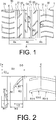
Wie in
Eine Mehrzahl von Stollenrillen
Eine Mehrzahl von Stollenrillen
Eine Mehrzahl von Stollenrillen
Im oben beschriebenen Luftreifen, wie in
Im oben beschriebenen Luftreifen sind Mehrzahlen von Stollenrillen
Im oben beschriebenen Luftreifen sind die Stollenrillen
Wenn bei dem oben beschriebenen Luftreifen der Abstand D1 von der Mittelposition Ce des Laufflächenabschnitts T zu den Mitten der Hauptrillen
Wenn außerdem die Breite der Hauptrillen
Bei dem oben beschriebenen Luftreifen ist eine Gesamtfläche der Stollenrillen
Außerdem ist das Rillenflächenverhältnis des Mittelbereichs Ac vorzugsweise so festgelegt, dass es in einem Bereich von 18% bis 22% liegt, und das Rillenflächenverhältnis der Schulterbereiche As ist vorzugsweise so festgelegt, dass es in einem Bereich von 25% bis 35% liegt. Dadurch können eine Verringerung des Fahrgeräuschs, eine Verringerung des Rollwiderstands und eine Verbesserung der Nassleistung in einem höheren Maße erreicht werden. Wenn das Rillenflächenverhältnis des Mittelbereichs Ac geringer als 18% ist, wird die Nassleistung negativ beeinflusst und der Rollwiderstand steigt. Wenn andererseits das Rillenflächenverhältnis 22% überschreitet, verstärkt sich das Fahrgeräusch und die Trockenleistung wird negativ beeinflusst. Wenn des Weiteren das Rillenflächenverhältnis der Schulterbereiche As geringer als 25% ist, wird die Nassleistung negativ beeinflusst und der Rollwiderstand steigt. Wenn andererseits das Rillenflächenverhältnis 35% übersteigt, verstärkt sich das Fahrgeräusch und die Trockenleistung wird negativ beeinflusst.In addition, the groove area ratio of the center area Ac is preferably set to be in a range of 18% to 22%, and the groove area ratio of the shoulder areas As is preferably set to be in a range of 25% to 35%. As a result, a reduction in the driving noise, a reduction in the rolling resistance and an improvement in the wet performance can be achieved to a greater extent. When the groove area ratio of the center area Ac is less than 18%, the wet performance is adversely affected and the rolling resistance increases. On the other hand, if the groove area ratio exceeds 22%, the driving noise increases and the dry performance is adversely affected. Further, when the groove area ratio of the shoulder areas As is less than 25%, the wet performance is adversely affected and the rolling resistance increases. On the other hand, if the groove area ratio exceeds 35%, the driving noise is increased and the dry performance is adversely affected.
Vorzugsweise ist eine Länge L1 in Reifenbreitenrichtung der Stollenrillen
Eine Rillenbreite an einer Position 3 mm zu einer Anfangsrandseite (offener Rand) hin von einem Endrand (geschlossener Rand) jeder der Stollenrillen
Teilungsabstände P1 und P2 (Anordnungsabstände in Reifenumfangsrichtung) der Stollenrillen
Außerdem ist vorzugsweise ein Neigungswinkel
Außerdem sind die Stollenrillen
BeispieleExamples
Reifen wurden für Vergleichsbeispiele 1 bis 5 und Ausführungsbeispiele 1 bis 4 hergestellt. Eine Reifengröße für jeden dieser Reifen war 195/65R15 91H. Ein Paar erster Hauptrillen, die auf beiden Seiten einer Mittelposition angeordnet sind und sich in Reifenumfangsrichtung erstrecken; ein Paar zweiter Hauptrillen, die weiter zu den Schulterseiten als die ersten Hauptrillen angeordnet sind und sich in Reifenumfangsrichtung erstrecken; eine zentrale Rippe, die zwischen dem Paar erster Hauptrillen angeordnet ist; Mittelrippen, die zwischen den ersten Hauptrillen und den zweiten Hauptrillen angeordnet sind; und Schulterrippen, die auf den Außenseiten der zweiten Hauptrillen angeordnet sind, wurden in einem Laufflächenabschnitt bereitgestellt. Mehrzahlen von Stollenrillen wurden jeweils in der zentralen Rippe, den Mittelrippen und den Schulterrippen gebildet, wobei die Stollenrillen für jeden Reifen unterschiedliche Strukturen aufwiesen.Tires were made for Comparative Examples 1 to 5 and Working Examples 1 to 4. One tire size for each of these tires was 195 / 65R15 91H. A pair of first main grooves disposed on both sides of a central position and extending in the tire circumferential direction; a pair of second main grooves disposed farther to the shoulder sides than the first main grooves and extending in the tire circumferential direction; a central rib disposed between the pair of first main grooves; Central ribs disposed between the first main grooves and the second main grooves; and shoulder ribs disposed on the outer sides of the second main grooves were provided in a tread portion. Multiple numbers of lug grooves were formed in each of the central rib, the midribs and the shoulder ribs, with the lug grooves having different structures for each tire.
Die Reifen der Vergleichsbeispiele 1 bis 4 und der Ausführungsbeispiele 1 bis 4 sind Reifen, in denen, wie in
In Vergleichsbeispielen 1 bis 5 und Ausführungsbeispielen 1 bis 4 wurden die Breite der ersten Hauptrillen, die Breite der zweiten Hauptrillen, das Verhältnis der Gesamtfläche der ersten Hauptrillen und der zweiten Hauptrillen in Bezug auf die Fläche des Bodenkontaktbereichs des Laufflächenabschnitts (als ”Hauptrillenflächenverhältnis” in der Tabelle angegeben), das Verhältnis des Abstands D1 von der Mittelposition des Laufflächenabschnitts zu den Mitten der ersten Hauptrillen in Bezug auf den Abstand D0 von der Mittelposition zum Bodenkontaktrand des Laufflächenabschnitts (D1/D0 × 100%), das Verhältnis des Abstands D2 von der Mittelposition des Laufflächenabschnitts zu den Mitten der zweiten Hauptrillen in Bezug auf den Abstand D0 von der Mittelposition zum Bodenkontaktrand des Laufflächenabschnitts (D2/D0 × 100%), das Rillenflächenverhältnis des Mittelbereichs, das Rillenflächenverhältnis der Schulterbereiche und das Verhältnis der Gesamtfläche der Stollenrillen, die im Mittelbereich vorhanden sind, in Bezug auf die Gesamtfläche der Stollenrillen, die in den Schulterbereichen vorhanden sind (als „Stollenrillenflächenverhältnis” in der Tabelle angegeben) wie in Tabelle 1 angegeben festgelegt.In Comparative Examples 1 to 5 and Working Examples 1 to 4, the width of the first main grooves, the width of the second main grooves, the ratio of the total area of the first main grooves and the second main grooves with respect to the area of the ground contact area of the tread portion (referred to as "main groove area ratio" in FIG Table), the ratio of the distance D1 from the center position of the tread portion to the centers of the first main grooves with respect to the distance D0 from the center position to the bottom contact edge of the tread portion (D1 / D0 × 100%), the ratio of the distance D2 from the center position of the tread portion to the centers of the second main grooves with respect to the distance D0 from the center position to the bottom contact edge of the tread portion (D2 / D0 × 100%), the groove area ratio the center area, the groove area ratio of the shoulder areas and the ratio of the total area of the lug grooves existing in the center area with respect to the total area of the lug grooves present in the shoulder areas (indicated as "lug groove area ratio" in the table) as shown in Table 1 established.
In den Vergleichsbeispielen 1 bis 4 und den Ausführungsbeispielen 1 bis 4 ist außerdem die Länge L1 in Reifenbreitenrichtung der Stollenrillen, die in der zentralen Rippe gebildet sind, so festgelegt, dass sie 50% der halben Breite W1 der zentralen Rippe beträgt; eine Länge L2 in Reifenbreitenrichtung der Stollenrillen, die in den Mittelrippen gebildet sind, ist so festgelegt, dass sie 70% einer Breite W2 der Mittelrippen beträgt; und eine Rillenbreite an einer Position 3 mm zu einer Anfangsrandseite hin von einem Endrand jeder der Stollenrillen, die in der zentralen Rippe und den Mittelrippen gebildet sind, ist so festgelegt, dass sie 70% einer Rillenbreite an einer Position 3 mm zu einer Endrandseite hin von einem Anfangsrand beträgt. Ein Teilungsabstand der Stollenrillen, die in der zentralen Rippe und den Mittelrippen gebildet sind, wurde so festgelegt, dass er das Zweifache eines Teilungsabstands der Stollenrillen beträgt, die in den Schulterrippen gebildet sind. Der Neigungswinkel
Diese Testreifen wurden hinsichtlich Fahrgeräuschs, Rollwiderstands, der Lenkstabilität auf trockenen Straßenoberflächen und der Lenkstabilität auf nassen Straßenoberflächen gemäß den folgenden Bewertungsmethoden bewertet. Die Ergebnisse davon werden in Tabelle 1 angegeben.These test tires were evaluated for road noise, rolling resistance, steering stability on dry road surfaces and steering stability on wet road surfaces according to the following evaluation methods. The results thereof are shown in Table 1.
Fahrgeräusch: Jeder Testreifen wurde auf ein Rad mit einer Felgengröße von 15 × 6JJ montiert, auf einen Luftdruck von 230 kPa aufgepumpt und an einem Testfahrzeug angebracht. Das Fahrgeräusch (dB) wurde gemäß den Messmethoden auf Grundlage der Maßgaben für die Messung von EEC/ECE Reifengeräuschen gemessen, die in den europäischen Vorschriften für „Fahrgeräusche” zu finden sind.Driving Noise: Each test tire was mounted on a wheel with a rim size of 15x6JJ, inflated to an air pressure of 230 kPa, and attached to a test vehicle. The driving noise (dB) was measured according to the measurement methods based on the requirements for the measurement of EEC / ECE tire noise found in the European Driving Noise Regulations.
Rollwiderstand: Jeder Testreifen wurde auf ein Rad mit einer Felgengröße von 15 × 6JJ montiert und auf einen Luftdruck von 230 kPa aufgepumpt. Der Rollwiderstand bei einer Geschwindigkeit von 80 km/h wurde gemessen. Die Bewertungsergebnisse sind als Index dargestellt, wobei Vergleichsbeispiel 1 für 100 steht. Kleinere Indexwerte zeigen weniger Rollwiderstand an.Rolling resistance: Each test tire was mounted on a wheel with a rim size of 15x6JJ and inflated to an air pressure of 230 kPa. The rolling resistance at a speed of 80 km / h was measured. The evaluation results are shown in index, Comparative Example 1 being 100. Smaller index values indicate less rolling resistance.
Lenkstabilität auf trockenen Straßenoberflächen: Jeder Testreifen wurde auf ein Rad mit einer Felgengröße von 15 × 6JJ montiert, auf einen Luftdruck von 230 kPa aufgepumpt und an einem Testfahrzeug angebracht. Eine sensorische Bewertung durch einen Testfahrer wurde auf einer trockenen Straßenoberfläche durchgeführt. Die Ergebnisse wurden mit einer 5-Punkte-Methode bewertet, mit Vergleichsbeispiel 1 als 3 (Bezugsergebnis). Höhere Ergebnisse zeigen überlegene Lenkstabilität auf trockenen Straßenoberflächen an.Steering stability on dry road surfaces: Each test tire was mounted on a wheel with a rim size of 15x6JJ, inflated to an air pressure of 230 kPa and attached to a test vehicle. A sensory evaluation by a test driver was done on a dry road surface. The results were evaluated by a 5-point method, Comparative Example 1 as 3 (reference result). Higher results indicate superior steering stability on dry road surfaces.
Lenkstabilität auf nassen Straßenoberflächen: Jeder Testreifen wurde auf ein Rad mit einer Felgengröße von 15 × 6JJ montiert, auf einen Luftdruck von 230 kPa aufgepumpt und an einem Testfahrzeug angebracht. Eine sensorische Bewertung durch einen Testfahrer wurde auf einer nassen Straßenoberfläche durchgeführt. Die Ergebnisse wurden mit einer 5-Punkte-Methode bewertet, mit Vergleichsbeispiel 1 als 3 (Bezugsergebnis). Höhere Ergebnisse zeigen überlegene Lenkstabilität auf nassen Straßenoberflächen an. Tabelle 1
Aus Tabelle 1 geht deutlich hervor, dass die Reifen der Ausführungsbeispiele 1 bis 4, verglichen mit dem Vergleichsbeispiel 1, jeweils in der Lage waren, das Fahrgeräusch zu verringern, während sie gleichzeitig einen ausgezeichneten Rollwiderstand und ausgezeichnete Nassleistung beibehielten. Bei dem Reifen von Vergleichsbeispiel 2 waren andererseits die ersten Hauptrillen der Mittelseiten übermäßig schmal im Vergleich zu den zweiten Hauptrillen der Schulterseiten, und dadurch war die Lenkstabilität auf nassen Straßenoberflächen negativ beeinflusst. Bei dem Reifen des Vergleichsbeispiels 3 waren die ersten Hauptrillen der Mittelseiten breiter als die zweiten Hauptrillen der Schulterseiten und dadurch verstärkte sich das Fahrgeräusch und die Lenkstabilität auf trockenen Straßenoberflächen wurde negativ beeinflusst. Bei dem Reifen des Vergleichsbeispiels 4 waren die ersten Hauptrillen der Mittelseiten übermäßig nah an der Mittelposition des Laufflächenabschnitts und dadurch verstärkte sich das Fahrgeräusch und die Lenkstabilität auf trockenen Straßenoberflächen wurde negativ beeinflusst. Bei dem Reifen des Vergleichsbeispiels 5 waren die Rippen von den Stollenrillen geteilt und dadurch verstärkte sich das Fahrgeräusch und die Lenkstabilität auf trockenen Straßenoberflächen war negativ beeinflusst.From Table 1, it can be clearly seen that the tires of Working Examples 1 to 4 were capable of reducing the driving noise, respectively, as compared with Comparative Example 1, while maintaining excellent rolling resistance and excellent wet performance. On the other hand, in the tire of Comparative Example 2, the first main grooves of the center sides were excessively narrow in comparison with the second main grooves of the shoulder sides, and thereby the steering stability on wet road surfaces was adversely affected. In the tire of Comparative Example 3, the first main grooves of the center sides were wider than the second main grooves of the shoulder sides, and thereby the driving noise increased, and the steering stability on dry road surfaces was adversely affected. In the tire of Comparative Example 4, the first main grooves of the center sides were excessively close to the center position of the tread portion, and thereby the driving noise increased, and the steering stability on dry road surfaces was adversely affected. In the tire of Comparative Example 5, the ribs were divided by the lug grooves, and thereby the driving noise increased, and the steering stability on dry road surfaces was adversely affected.
Bezugszeichenliste LIST OF REFERENCE NUMBERS
- 11
- Hauptrille (erste Hauptrille)Main groove (first main groove)
- 22
- Hauptrille (zweite Hauptrille)Main groove (second main groove)
- 1010
- Zentrale RippeCentral rib
- 1111
- Stollenrillelug groove
- 2020
- Mittelrippemidrib
- 2121
- Stollenrillelug groove
- 3030
- Schulterrippeshoulder rib
- 3131
- Stollenrillelug groove
- AA
- BodenkontaktbereichGround contact area
- AcAc
- Mittelbereichthe central region
- Asace
- Schulterbereichshoulders
- CeCe
- Mittelpositioncenter position
- Ee
- BodenkontaktrandGround contact edge
- TT
- LaufflächenabschnittTread portion
ZITATE ENTHALTEN IN DER BESCHREIBUNG QUOTES INCLUDE IN THE DESCRIPTION
Diese Liste der vom Anmelder aufgeführten Dokumente wurde automatisiert erzeugt und ist ausschließlich zur besseren Information des Lesers aufgenommen. Die Liste ist nicht Bestandteil der deutschen Patent- bzw. Gebrauchsmusteranmeldung. Das DPMA übernimmt keinerlei Haftung für etwaige Fehler oder Auslassungen.This list of the documents listed by the applicant has been generated automatically and is included solely for the better information of the reader. The list is not part of the German patent or utility model application. The DPMA assumes no liability for any errors or omissions.
Zitierte PatentliteraturCited patent literature
- JP 2006-224770 [0004] JP 2006-224770 [0004]
Claims (6)
Applications Claiming Priority (2)
| Application Number | Priority Date | Filing Date | Title |
|---|---|---|---|
| JP2011-024790 | 2011-02-08 | ||
| JP2011024790A JP5287894B2 (en) | 2011-02-08 | 2011-02-08 | Pneumatic tire |
Publications (2)
| Publication Number | Publication Date |
|---|---|
| DE102012201631A1 true DE102012201631A1 (en) | 2012-08-09 |
| DE102012201631A9 DE102012201631A9 (en) | 2012-12-06 |
Family
ID=46547203
Family Applications (1)
| Application Number | Title | Priority Date | Filing Date |
|---|---|---|---|
| DE102012201631A Pending DE102012201631A1 (en) | 2011-02-08 | 2012-02-03 | tire |
Country Status (3)
| Country | Link |
|---|---|
| JP (1) | JP5287894B2 (en) |
| CN (1) | CN102632772B (en) |
| DE (1) | DE102012201631A1 (en) |
Cited By (2)
| Publication number | Priority date | Publication date | Assignee | Title |
|---|---|---|---|---|
| US20130167997A1 (en) * | 2011-12-29 | 2013-07-04 | Sumitomo Rubber Industries, Ltd. | Pneumatic tire |
| CN104057784A (en) * | 2013-03-19 | 2014-09-24 | 住友橡胶工业株式会社 | Pneumatic tire |
Families Citing this family (13)
| Publication number | Priority date | Publication date | Assignee | Title |
|---|---|---|---|---|
| JP2014162300A (en) * | 2013-02-22 | 2014-09-08 | Yokohama Rubber Co Ltd:The | Pneumatic tire |
| US10710414B2 (en) * | 2013-06-10 | 2020-07-14 | Compagnie Generale Des Etablissements Michelin | Tire comprising an improved tread |
| JP6494156B2 (en) * | 2013-06-24 | 2019-04-03 | 横浜ゴム株式会社 | Pneumatic tire |
| JP5779211B2 (en) * | 2013-09-04 | 2015-09-16 | 住友ゴム工業株式会社 | Motorcycle tires |
| JP6228034B2 (en) * | 2014-02-26 | 2017-11-08 | 株式会社ブリヂストン | Pneumatic tire |
| CN105980173B (en) * | 2014-05-22 | 2017-10-13 | 横滨橡胶株式会社 | Pneumatic tire |
| JP6249930B2 (en) * | 2014-11-26 | 2017-12-20 | 横浜ゴム株式会社 | Pneumatic tire |
| JP6063918B2 (en) * | 2014-12-26 | 2017-01-18 | 住友ゴム工業株式会社 | Pneumatic tire |
| JP6634711B2 (en) * | 2015-06-08 | 2020-01-22 | 横浜ゴム株式会社 | Pneumatic tire |
| JP6187573B2 (en) * | 2015-12-04 | 2017-08-30 | 横浜ゴム株式会社 | Pneumatic tire |
| JP7097178B2 (en) * | 2017-12-12 | 2022-07-07 | Toyo Tire株式会社 | Pneumatic tires |
| JP7020285B2 (en) * | 2018-05-15 | 2022-02-16 | 横浜ゴム株式会社 | Pneumatic tires |
| JP7163136B2 (en) * | 2018-10-22 | 2022-10-31 | Toyo Tire株式会社 | pneumatic tire |
Citations (1)
| Publication number | Priority date | Publication date | Assignee | Title |
|---|---|---|---|---|
| JP2006224770A (en) | 2005-02-16 | 2006-08-31 | Yokohama Rubber Co Ltd:The | Pneumatic tire |
Family Cites Families (11)
| Publication number | Priority date | Publication date | Assignee | Title |
|---|---|---|---|---|
| JP3471396B2 (en) * | 1993-12-17 | 2003-12-02 | 横浜ゴム株式会社 | Pneumatic radial tires for passenger cars |
| JPH11123909A (en) * | 1997-10-24 | 1999-05-11 | Bridgestone Corp | Pneumatic tire |
| JP4286363B2 (en) * | 1999-02-10 | 2009-06-24 | 株式会社ブリヂストン | Pneumatic tire having directional inclined grooves |
| JP4439658B2 (en) * | 2000-02-14 | 2010-03-24 | 住友ゴム工業株式会社 | Pneumatic tire |
| CN2445952Y (en) * | 2000-03-23 | 2001-09-05 | 广州市华南橡胶轮胎有限公司 | Pattern of inflatting radial tire |
| JP2008037139A (en) * | 2006-08-01 | 2008-02-21 | Yokohama Rubber Co Ltd:The | Pneumatic tire |
| JP4107393B1 (en) * | 2007-10-12 | 2008-06-25 | 横浜ゴム株式会社 | Pneumatic tire |
| JP2009096255A (en) * | 2007-10-15 | 2009-05-07 | Bridgestone Corp | Pneumatic tire |
| JP4367667B1 (en) * | 2008-06-04 | 2009-11-18 | 横浜ゴム株式会社 | Pneumatic tire |
| JP4407765B1 (en) * | 2008-09-08 | 2010-02-03 | 横浜ゴム株式会社 | Pneumatic tire |
| JP4729096B2 (en) * | 2008-12-05 | 2011-07-20 | 住友ゴム工業株式会社 | Pneumatic tire |
-
2011
- 2011-02-08 JP JP2011024790A patent/JP5287894B2/en active Active
-
2012
- 2012-02-03 DE DE102012201631A patent/DE102012201631A1/en active Pending
- 2012-02-07 CN CN201210026224.0A patent/CN102632772B/en active Active
Patent Citations (1)
| Publication number | Priority date | Publication date | Assignee | Title |
|---|---|---|---|---|
| JP2006224770A (en) | 2005-02-16 | 2006-08-31 | Yokohama Rubber Co Ltd:The | Pneumatic tire |
Cited By (4)
| Publication number | Priority date | Publication date | Assignee | Title |
|---|---|---|---|---|
| US20130167997A1 (en) * | 2011-12-29 | 2013-07-04 | Sumitomo Rubber Industries, Ltd. | Pneumatic tire |
| US9283814B2 (en) * | 2011-12-29 | 2016-03-15 | Sumitomo Rubber Industries, Ltd. | Pneumatic tire |
| CN104057784A (en) * | 2013-03-19 | 2014-09-24 | 住友橡胶工业株式会社 | Pneumatic tire |
| CN104057784B (en) * | 2013-03-19 | 2017-11-14 | 住友橡胶工业株式会社 | Pneumatic tire |
Also Published As
| Publication number | Publication date |
|---|---|
| JP2012162194A (en) | 2012-08-30 |
| CN102632772A (en) | 2012-08-15 |
| JP5287894B2 (en) | 2013-09-11 |
| DE102012201631A9 (en) | 2012-12-06 |
| CN102632772B (en) | 2016-03-16 |
Similar Documents
| Publication | Publication Date | Title |
|---|---|---|
| DE102012201631A1 (en) | tire | |
| DE112014003255B4 (en) | tire | |
| DE112016000774T9 (en) | tire | |
| DE112017002741T5 (en) | tire | |
| DE112014004035B4 (en) | tire | |
| DE102014109864A1 (en) | Pneumatic tires | |
| DE112015002715T5 (en) | tire | |
| DE102011009558B4 (en) | tire | |
| DE112011100473B4 (en) | TIRE | |
| DE112017007085T5 (en) | tire | |
| DE102019126482A1 (en) | Pneumatic tire | |
| DE102011083509A1 (en) | tire | |
| DE102019111987A1 (en) | Pneumatic tire | |
| DE112017006817T5 (en) | tire | |
| DE102013206479A1 (en) | tire | |
| DE112008002502B4 (en) | tire | |
| DE102009049500A1 (en) | tire | |
| DE102018221498B4 (en) | Pneumatic tire | |
| DE112014004042B4 (en) | tire | |
| DE102012213997A1 (en) | tire | |
| DE112017007076T5 (en) | tire | |
| DE112017007175T9 (en) | tire | |
| DE102018221483A1 (en) | Pneumatic tire | |
| DE112018001172T5 (en) | tire | |
| DE112018000414T5 (en) | tire |
Legal Events
| Date | Code | Title | Description |
|---|---|---|---|
| R012 | Request for examination validly filed | ||
| R016 | Response to examination communication | ||
| R016 | Response to examination communication |