Hintergrund der ErfindungBackground of the invention
1. Gebiet der Erfindung1. Field of the invention
Die vorliegende Erfindung betrifft eine Kraftstofffüllmündung, die verhindert, dass ein Kraftstoff überläuft, wenn der Kraftstoff zugeführt wird.The present invention relates to a fuel filler orifice which prevents fuel from overflowing when the fuel is supplied.
2. Beschreibung der verwandten Technik2. Description of the Related Art
Wenn ein Kraftstoff in einen Kraftstoffbehälter eines Fahrzeugs zugeführt wird, wird ein Kraftstoffstutzen in eine Kraftstoffeinfüllmündung eingesetzt, und der Kraftstoff wird über eine Kraftstoffeinfüllleitung von der Kraftstoffeinfüllmündung an den Kraftstoffbehälter geliefert. Der Kraftstoffstutzen stoppt die Zuführung des Kraftstoffs automatisch, wenn der Kraftstoffbehälter aufgefüllt ist. Der Kraftstoffeinfüllstutzen stoppt die Lieferung des Kraftstoffs, indem er mit einem Sensor eine Druckänderung in dem Kraftstoffbehälter erfasst. Die Druckänderung wird durch Ändern eines Flüssigkeitspegels des Kraftstoffbehälters bewirkt. Jedoch füllt ein Auftankbediener den Kraftstoffbehälter häufig manuell nach, indem er den Kraftstoff manuell hinzufügt, da ein Zuführen des Kraftstoffs nicht ordentlich stoppt, wenn der Kraftstoffbehälter abhängig von dem Fahrzeugtyp aufgefüllt wird. Wenn der Bediener den Kraftstoffbehälter manuell mit dem Kraftstoff nachfüllt, wird der Kraftstoff schnell aus dem Kraftstoffstutzen abgegeben und läuft aus der Kraftstoffeinfüllmündung über, so dass er über Bediener verschüttet wird. Eine Fehlfunktion des Sensors bewirkt die gleiche Art von Schwierigkeiten.When a fuel is supplied into a fuel tank of a vehicle, a fuel nozzle is inserted into a fuel filler port, and the fuel is supplied from the fuel filler port to the fuel tank via a fuel filler pipe. The fuel nozzle automatically stops feeding the fuel when the fuel tank is filled up. The fuel filler neck stops delivery of the fuel by detecting a pressure change in the fuel tank with a sensor. The pressure change is effected by changing a liquid level of the fuel tank. However, a refueling operator often replenishes the fuel tank manually by manually adding the fuel, since supplying the fuel does not stop properly when the fuel tank is replenished depending on the type of the vehicle. When the operator manually refills the fuel tank with fuel, the fuel is quickly exhausted from the fuel nozzle and drains from the fuel filler neck so that it is spilled by operators. A malfunction of the sensor causes the same kind of difficulties.
Eine Kraftstoffeinfüllmündung, die in der internationalen PCT-Veröffentlichung Nr. WO2010/029989A1 offenbart ist, schließt eine Öffnung der Kraftstoffeinfüllmündung mit einer darin bereitgestellten Absperrung 26. In dem Fall, dass die Absperrung 26 sich aus irgendwelchen Gründen nicht öffnet, wird ein Ende des Kraftstoffeinfüllstutzens mit der Absperrung 26 versperrt. Dies kann bewirken, dass der Kraftstoff aus der Kraftstoffeinfüllmündung überläuft. In der Kraftstoffeinfüllmündung von WO2010/029989A1 ist ein Strömungsweg mit einer komplexen Struktur, ein sogenanntes „Labyrinth„, zwischen der Öffnung der Kraftstoffeinfüllmündung 73 und der Absperrung 26 bereitgestellt. Das Labyrinth 81 schwächt einen vorbeischießenden Kraftstoff, so dass er langsam aus der Öffnung der Kraftstoffeinfüllmündung abgegeben wird.A fuel filler neck disclosed in PCT International Publication No. WO2010 / 029989A1 discloses an opening of the fuel filler mouth with a barrier provided therein 26 , In the event that the barrier 26 does not open for any reason, one end of the fuel filler neck with the barrier 26 blocked. This can cause the fuel to overflow from the fuel filler throat. In the fuel filler mouth of WO2010 / 029989A1 is a flow path with a complex structure, a so-called "labyrinth", between the opening of the fuel filler neck 73 and the barrier 26 provided. the maze 81 weakens a passing fuel so that it is slowly released from the opening of the fuel filler neck.
In der Kraftstoffeinfüllmündung von WO2010/029989A1 sind erste und zweite Portionierungsteile 28, 52 zwischen der Absperrung 26 und der Öffnung der Kraftstoffeinfüllmündung 73 bereitgestellt, um zuzulassen, dass der Kraftstoffeinfüllstutzen dazwischen hindurch geht. Der erste Unterteilungsteil 28, der um eine erste Öffnung 65 herum bereitgestellt ist, hat wenigstens einen ersten hohlen Teil 68 mit einer vorgegebenen Umfangsgröße. Der zweite Unterteilungsteil 52, der um eine zweite Öffnung 61 bereitgestellt ist, hat wenigstens einen zweiten hohlen Teil 76 mit einer vorgegebenen Umfangsgröße. Die ersten und zweiten hohlen Teile 68, 76 sind dem Umfang nach an zueinander unterschiedlichen Positionen angeordnet, um dabei ein Labyrinth 81 zwischen der Absperrung 26 und der Öffnung der Kraftstoffeinfüllmündung 73 zu bilden. Wie in Anspruch 3 und 8b gezeigt, sind abgeschrägte Teile 75 auf einer Ecke der zweiten Öffnung 61 ausgebildet, um eine Strömungsgeschwindigkeit des Kraftstoffs zu verringern.In the fuel filler mouth of WO2010 / 029989A1 are first and second portion portions 28 . 52 between the barrier 26 and the opening of the fuel filler neck 73 provided to allow the fuel filler neck to pass therebetween. The first subdivision part 28 that is around a first opening 65 around has at least a first hollow part 68 with a given circumferential size. The second subdivision part 52 , which has a second opening 61 is provided has at least a second hollow part 76 with a given circumferential size. The first and second hollow parts 68 . 76 are arranged circumferentially at mutually different positions to thereby a labyrinth 81 between the barrier 26 and the opening of the fuel filler neck 73 to build. As in claim 3 and 8b Shown are beveled parts 75 on a corner of the second opening 61 designed to reduce a flow rate of the fuel.
Die Kraftstoffeinfüllmündung WO2010/029989A1 schwächt lediglich den vorbeischießenden Kraftstoff. Der Kraftstoff wird, wie durch einen Pfeil H in 9(b) angezeigt, möglicherweise immer noch aus der Kraftstoffeinfüllmündung abgegeben. Daher wird der Kraftstoff möglicherweise über den Bediener verschüttet, wenn der vorbeischießende Kraftstoff nicht genug geschwächt ist.The fuel filler outlet WO2010 / 029989A1 only weakens the passing fuel. The fuel, as indicated by an arrow H in 9 (b) displayed, may still be emitted from the fuel filler neck. Therefore, the fuel may spill over the operator if the passing fuel is not sufficiently weakened.
Zusammenfassung der ErfindungSummary of the invention
Die vorliegende Erfindung stellt eine Kraftstoffeinfüllmündung bereit, die verhindert, dass ein zurückfließender Kraftstoff aus der Kraftstoffeinfüllmündung überläuft. Eine derartige Kraftstoffeinfüllmündung wird durch eine Kraftstoffeinfüllmündung realisiert, die auf einem Ende einer Kraftstoffeinfüllleitung installiert werden soll, die mit einem Kraftstoffeinfüllbehälter in Verbindung steht. Die Kraftstoffeinfüllmündung umfasst ein erstes Element, das quer zu einer Einsetzrichtung des Kraftstoffeinfüllstutzens angeordnet ist und mit einer ersten Öffnung zum Einsetzen des Kraftstoffeinfüllstutzens versehen ist. Ein Innendurchmesser der ersten Öffnung ist gleich einem Außendurchmesser des Kraftstoffeinfüllstutzens. Die Kraftstoffeinfüllmündung umfasst ferner ein zweites Element, das quer zu einer Einsetzrichtung des Kraftstoffeinfüllstutzens angeordnet ist. Das zweite Element ist versehen mit: einer zweiten Öffnung zum Einsetzen des Kraftstoffeinfüllstutzens, einer Vielzahl von Führungsvorsprüngen, die einen Raum zum Führen des Kraftstoffeinfüllstutzens zu der Kraftstoffeinfüllleitung bilden und von einem Umfangsrand der zweiten Öffnung intermittierend vorstehen, einer vorstehenden Öffnung, die von der zweiten Öffnung radial nach außen vorsteht und zwischen den benachbarten Führungsvorsprüngen bereitgestellt ist, und einem Kraftstoffauslass, der zwischen benachbarten Führungsvorsprüngen bereitgestellt ist und mit einem Raum, der von den Führungsvorsprüngen umschlossen ist, und einem Raum außerhalb der Kraftstoffeinfüllleitung in Verbindung steht. In der Kraftstoffeinfüllmündung dieser Erfindung sind das erste Element und das zweite Element von oben nach unten in der niedergeschriebenen Reihenfolge bereitgestellt. Gemäß der vorliegenden Erfindung wird ein zurückfließender Kraftstoff durch die vorstehende Öffnung und den Kraftstoffauslass nach außen abgegeben.The present invention provides a fuel filler throat that prevents backflow of fuel from overflowing the fuel filler throat. Such a fuel filler port is realized by a fuel filler port to be installed on an end of a fuel filler pipe communicating with a fuel filler tank. The fuel filler mouth includes a first member disposed transversely to an insertion direction of the fuel filler neck and provided with a first opening for inserting the fuel filler neck. An inner diameter of the first opening is equal to an outer diameter of the fuel filler neck. The fuel filler mouth further includes a second member disposed transversely to an insertion direction of the fuel filler neck. The second member is provided with: a second opening for inserting the fuel filler nozzle, a plurality of guide protrusions forming a space for guiding the fuel filler nozzle to the fuel filler pipe and intermittently protruding from a peripheral edge of the second opening, a protruding opening formed from the second opening projecting radially outward and provided between the adjacent guide protrusions, and a fuel outlet provided between adjacent guide protrusions and communicating with a space enclosed by the guide protrusions and a space outside the fuel filler pipe. In the fuel filler neck of this invention, the first element and the second element provided from top to bottom in the written order. According to the present invention, a returning fuel is discharged outside through the above opening and the fuel outlet.
Eine Spitze des Kraftstoffeinfüllstutzens ist durch einen Öffnungsrand des Einfüllhalses, die erste Öffnung des ersten Elements und die zweite Öffnung des zweiten Elements in die Kraftstoffeinfüllleitung eingesetzt. Das erste Element ist derart aufgebaut, dass ein Innendurchmesser der ersten Öffnung gleich dem Außendurchmesser des Kraftstoffeinfüllstutzens ist. Ein Begriff „gleich„ in dieser Erfindung bedeutet, dass ein innerer Rand der ersten Öffnung und ein äußerer Rand des Kraftstoffeinfüllstutzens so nahe sind, dass sich kaum eine Lücke zwischen ihnen bildet. Jedoch bedeutet dies nicht immer, dass eine Größe des Innendurchmessers der ersten Öffnung und eine Größe des Außendurchmessers des Kraftstoffeinfüllstutzens genau gleich sind. Die Größe des Innendurchmessers der ersten Öffnung kann ein bisschen größer als die Größe des Außendurchmessers des Kraftstoffeinfüllstutzens sein. Mit anderen Worten ist der Innendurchmesser der ersten Öffnung derart aufgebaut, dass ein Druck des Kraftstoffs, dem es gelingt, durch eine Lücke zwischen der ersten Öffnung und dem Kraftstoffeinfüllstutzen hindurch zu gehen, hoch wird. Das zweite Element umfasst den Kraftstoffauslass, der zwischen der Vielzahl von Führungsvorsprüngen bereitgestellt ist. Daher fließt der zurückfließende Kraftstoff kaum zu der ersten Öffnung und einer Innenoberfläche des Führungsvorsprungs, wo der Druck hoch wird, und der zurück fließende Kraftstoff sammelt sich an dem Kraftstoffauslass. Als ein Ergebnis wird der Kraftstoff durch den Kraftstoffauslass nach außen abgegeben. Die Verwendung des Begriffs „gleich„ ist auf die anderen Beschreibungen der vorliegenden Erfindung ebenfalls anwendbar.A tip of the fuel filler nozzle is inserted through an opening edge of the filler neck, the first opening of the first member, and the second opening of the second member into the fuel filler pipe. The first member is constructed such that an inner diameter of the first opening is equal to the outer diameter of the fuel filler nozzle. A term "equal" in this invention means that an inner edge of the first opening and an outer edge of the fuel filler nozzle are so close that hardly a gap is formed between them. However, this does not always mean that a size of the inner diameter of the first opening and a size of the outer diameter of the fuel filler nozzle are exactly the same. The size of the inner diameter of the first opening may be slightly larger than the size of the outer diameter of the fuel filler neck. In other words, the inner diameter of the first opening is configured such that a pressure of the fuel that succeeds to pass through a gap between the first opening and the fuel filler neck becomes high. The second member includes the fuel outlet provided between the plurality of guide protrusions. Therefore, the returning fuel hardly flows to the first opening and an inner surface of the guide protrusion where the pressure becomes high, and the flowing back fuel accumulates at the fuel outlet. As a result, the fuel is discharged through the fuel outlet to the outside. The use of the term "equal" is also applicable to the other descriptions of the present invention.
In der Kraftstoffeinfüllmündung der vorliegenden Erfindung wird bevorzugt, dass das zweite Element ferner eine Kammer, die über den Kraftstoffauslass mit dem von den Führungsvorsprüngen umschlossenen Raum in Verbindung steht, und einen zweiten Kraftstoffauslass umfassen kann, der in der Kammer bereitgestellt ist, um mit dem Raum außerhalb der Kraftstoffeinfüllleitung in Verbindung zu stehen. Die Kammer hält den zurückfließenden Kraftstoff vorübergehend zurück. Der zurück gehaltene Kraftstoff fließt wieder zu der Kraftstoffeinfüllleitung zurück, nachdem ein Flüssigkeitspegel der Kraftstoffeinfüllleitung sich senkt.In the fuel filler neck of the present invention, it is preferable that the second member may further include a chamber communicating with the space enclosed by the guide protrusions via the fuel outlet and a second fuel outlet provided in the chamber with the space outside the fuel line. The chamber temporarily holds back the returning fuel. The retained fuel flows back to the fuel fill line after a liquid level of the fuel fill line lowers.
Falls die Kammer bereitgestellt ist, fließt der Kraftstoff, der vorübergehend in der Kammer zurückgehalten wird, möglicherweise zurück zu dem Raum, der von den mehreren Führungsvorsprüngen umschlossen ist. Daher wird es bevorzugt, dass ein Flussänderungsblock außerhalb des Kraftstoffauslasses bereitgestellt ist. Der Flussänderungsblock stößt mit einem Kraftstoff zusammen, der von dem Kraftstoffauslass abfließt, und ändert eine Strömungsrichtung in die Umfangsrichtung. Der Flussänderungsblock verhindert, dass der Kraftstoff in den Raum, der von den Führungsvorsprüngen umschlossen ist, zurückfließt, während er zulässt, dass der Kraftstoff von dem Kraftstoffauslass abläuft, indem der vorbeischießende Kraftsoff, der von dem Auslass abläuft, durch Zusammenstoßen damit geschwächt wird. Daher wird der Kraftstoff, der vorübergehend in der Kammer zurückgehalten wird, davon abgehalten, zurück in den Raum zu fließen.If the chamber is provided, the fuel temporarily retained in the chamber may flow back to the space enclosed by the plurality of guide projections. Therefore, it is preferable that a flow change block is provided outside the fuel outlet. The flow change block collides with a fuel flowing from the fuel outlet and changes a flow direction in the circumferential direction. The flow change block prevents the fuel from flowing back into the space enclosed by the guide protrusions while allowing the fuel to drain from the fuel outlet by weakening the passing fuel off the outlet by colliding therewith. Therefore, the fuel that is temporarily retained in the chamber is prevented from flowing back into the room.
Ein Aufbau des zweiten Elements variiert abhängig von einem Aufbau der Führungsvorsprünge. Zum Beispiel stehen die Führungsvorsprünge von einer Umfangsfläche einer zylindrischen Wand, deren Innendurchmesser größer als ein Außendurchmesser des Kraftstoffeinfüllstutzens ist, radial einwärts vor, und der Kraftstoffauslass ist wie in der vorstehend erwähnten Ausführungsform 1 auf der Umfangsoberfläche bereitgestellt, auf der die Führungsvorsprünge nicht bereitgestellt sind.A structure of the second member varies depending on a structure of the guide projections. For example, the guide protrusions project radially inward from a peripheral surface of a cylindrical wall whose inner diameter is larger than an outer diameter of the fuel filler nozzle, and the fuel outlet is provided on the circumferential surface as in the above-mentioned Embodiment 1 on which the guide protrusions are not provided.
Alternativ kann der Aufbau des Führungsvorsprungs wie folgt sein. Der Kraftstoffauslass ist auf einer Umfangsfläche einer zylindrischen Wand bereitgestellt, deren Innendurchmesser gleich einem Außendurchmesser des Kraftstoffeinfüllstutzens ist, und die Führungsvorsprünge sind die restlichen Zylinderwände, die wie in den vorstehend erwähnten Ausführungsformen 2 und 3 nicht mit dem Kraftstoffauslass versehen sind.Alternatively, the structure of the guide projection may be as follows. The fuel outlet is provided on a peripheral surface of a cylindrical wall whose inner diameter is equal to an outer diameter of the fuel filler nozzle, and the guide projections are the remaining cylinder walls which are not provided with the fuel outlet as in the aforementioned embodiments 2 and 3.
Alternativ kann der Aufbau des Führungsvorsprungs wie folgt sein. Die zweite Öffnung ist mit einer Vielzahl von vorstehenden Umfangsflächen und einer Vielzahl konkaver Umfangsflächen versehen, wobei die vorstehenden Umfangsflächen und die konkaven Umfangsflächen abwechselnd in der Umfangsrichtung der zweiten Öffnung kombiniert und ausgerichtet sind. Ein Abstand zwischen den entgegengesetzten konkaven Umfangsflächen ist größer als ein Außendurchmesser des Kraftstoffeinfüllstutzens und ein Außendurchmesser eines unteren Endes des ersten Elements. Ein Abstand zwischen den Innenflächen der entgegengesetzten vorstehenden Umfangsflächen ist gleich dem Außendurchmesser des Kraftstoffeinfüllstutzens. In diesem Fall wirken vorstehende Umfangsflächen als die Führungsvorsprünge. Eine Öffnung zwischen einem oberen Ende der konkaven Umfangsfläche und dem unteren Ende des ersten Elements wirkt wie in der vorstehend erwähnten Ausführungsform 4 als der der Kraftstoffauslass. Ein Kraftstoffeinfüllstutzen ist in den Raum eingesetzt, der von den vorstehenden Umfangsflächen und den konkaven Umfangsflächen umgeben ist.Alternatively, the structure of the guide projection may be as follows. The second opening is provided with a plurality of protruding peripheral surfaces and a plurality of concave peripheral surfaces, wherein the protruding peripheral surfaces and the concave peripheral surfaces are alternately combined and aligned in the circumferential direction of the second opening. A distance between the opposed concave peripheral surfaces is larger than an outer diameter of the fuel filler nozzle and an outer diameter of a lower end of the first member. A distance between the inner surfaces of the opposite protruding peripheral surfaces is equal to the outer diameter of the fuel filler neck. In this case, projecting peripheral surfaces act as the guide projections. An opening between an upper end of the concave peripheral surface and the lower end of the first member acts as the fuel outlet, as in the aforementioned embodiment 4. A fuel filler neck is inserted into the space surrounded by the protruding peripheral surfaces and the concave peripheral surfaces.
Die Kraftstoffeinfüllmündung der vorliegenden Erfindung ist vorzugsweise mit einer Absperrung, versehen. In diesem Fall stehen die Führungsvorsprünge von einem Umfangsrand der zweiten Öffnung radial einwärts vor, um eine vorstehende Öffnung zwischen den benachbarten Führungsvorsprüngen zu bilden, und die vorstehende Öffnung steht mit der zweiten Öffnung in Verbindung. Die vorstehend genannte Absperrung wird als ein Ventilsitz gegen die zweite Öffnung und die vorstehende Öffnung gedrückt. Falls der Kraftstoffeinfüllstutzen in die zweite Öffnung eingesetzt ist, lässt es die vorstehende Öffnung zu, dass der zurückfließende Kraftstoff hindurch geht. Falls der Kraftstoffeinfüllstutzen nicht eingesetzt wird, dichtet die Absperrung die zweite Öffnung und die vorstehende Öffnung ab und stellt die Gasdichtigkeit sicher. The fuel filler neck of the present invention is preferably provided with a barrier. In this case, the guide protrusions project radially inward from a peripheral edge of the second opening to form a protruding opening between the adjacent guide protrusions, and the protruding opening communicates with the second opening. The aforesaid barrier is pressed against the second opening and the projecting opening as a valve seat. If the fuel filler neck is inserted into the second opening, the protruding opening allows the returning fuel to pass. If the fuel filler neck is not used, the barrier seals the second opening and the protruding opening and ensures gas tightness.
Gemäß der Kraftstoffeinfüllmündung der vorliegenden Erfindung läuft der zurückfließende Kraftstoff nicht von dem Öffnungsrand der Kraftstoffeinfüllmündung über. Der zurückfließende Kraftstoff wird nicht über den nachtankenden Bediener verschüttet, da der zurückfließende Kraftstoff durch den Kraftstoffauslass abgegeben wird. Dies liegt daran, dass der Kraftstoff kaum durch die Lücke zwischen der ersten Öffnung und dem Kraftstoffeinfüllstutzen und die Lücke zwischen dem Führungsvorsprung und der ersten Öffnung geht, da der Druck an den Lücken hoch wird. Ein Umfang der Kraftstoffeinfüllmündung wird nicht mit dem Kraftstoff verunreinigt, da der zurück fließende Kraftstoff nicht von dem Öffnungsrand der Kraftstoffeinfüllmündung überläuft.According to the fuel filler neck of the present invention, the returning fuel does not overflow from the opening edge of the fuel filler neck. The returning fuel will not spill over the refueling operator as the returning fuel is discharged through the fuel outlet. This is because the fuel hardly goes through the gap between the first opening and the fuel filler neck and the gap between the guide projection and the first opening because the pressure at the gaps becomes high. A periphery of the fuel filler port is not contaminated with the fuel because the returning fuel does not overflow from the opening edge of the fuel filler port.
Kurze Beschreibung der ZeichnungenBrief description of the drawings
1 ist eine Perspektivansicht, die ein Aussehen einer Kraftstoffeinfüllmündung einer ersten Ausführungsform darstellt. 1 FIG. 10 is a perspective view illustrating an appearance of a fuel filler neck of a first embodiment. FIG.
2 ist eine vertikale Querschnittansicht der Kraftstoffeinfüllmündung der ersten Ausführungsform. 2 FIG. 12 is a vertical cross-sectional view of the fuel filler port of the first embodiment. FIG.
3 ist eine Draufsicht der Kraftstoffeinfüllmündung der ersten Ausführungsform. 3 FIG. 10 is a plan view of the fuel filler port of the first embodiment. FIG.
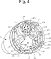
4 ist eine Perspektive, die ein Aussehen eines zweiten Elements darstellt, das die Kraftstoffeinfüllmündung der ersten Ausführungsform aufbaut. Der einfacheren Erklärung halber ist ein Status dargestellt, in dem eine Absperrung nach unten gedrückt ist und geöffnet ist. 4 Fig. 13 is a perspective illustrating an appearance of a second member constituting the fuel filler neck of the first embodiment. For convenience of explanation, a status is shown where a barrier is pressed down and open.
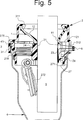
5 ist eine vertikale Querschnittansicht der Kraftstoffeinfüllmündung der ersten Ausführungsform, in die ein Kraftstoffeinfüllstutzen eingesetzt ist. Ein Querschnitt entspricht einer Ebene, die in 6 mit Pfeilen A markiert ist. 5 is a vertical cross-sectional view of the fuel filler mouth of the first embodiment, in which a fuel filler neck is inserted. A cross section corresponds to a plane in 6 marked with arrows A.
6 ist eine querlaufende Querschnittansicht der Kraftstoffeinfüllmündung der ersten Ausführungsform, in welche der Kraftstoffeinfüllstutzen eingesetzt ist. 6 is a transverse cross-sectional view of the fuel filler mouth of the first embodiment, in which the fuel filler neck is inserted.
7 ist eine 2 entsprechende vertikale Querschnittansicht, die eine Kraftstoffeinfüllmündung einer zweiten Ausführungsform darstellt. 7 is a 2 corresponding vertical cross-sectional view illustrating a fuel filler mouth of a second embodiment.
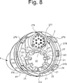
8 ist eine 4 entsprechende Perspektivansicht, die ein Aussehen eines zweiten Elements darstellt, das die Kraftstoffeinfüllmündung der zweiten Ausführungsform aufbaut. Der einfacheren Erklärung halber ist ein Zustand dargestellt, in dem eine Absperrung nach unten gedrückt ist und geöffnet ist. 8th is a 4 corresponding perspective view illustrating an appearance of a second element, which builds the fuel filler mouth of the second embodiment. For the sake of simpler explanation, a state is shown in which a barrier is pushed down and opened.
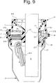
9 ist eine vertikale Querschnittansicht, die 5 entspricht, welche die Kraftstoffeinfüllmündung der zweiten Ausführungsform darstellt, in die ein Kraftstoffeinfüllstutzen eingesetzt ist. Ein Querschnitt entspricht einer Ebene, die in 10 mit Pfeilen B markiert ist. 9 is a vertical cross-sectional view, the 5 corresponding to the fuel filler port of the second embodiment, in which a fuel filler neck is inserted. A cross section corresponds to a plane in 10 marked with arrows B.
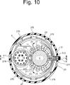
10 ist eine 6 entsprechende querlaufende Querschnittansicht, welche die Kraftstoffeinfüllmündung der zweiten Ausführungsform darstellt, in welche der Kraftstoffeinfüllstutzen eingesetzt ist. 10 is a 6 corresponding cross-sectional cross-sectional view illustrating the fuel filler mouth of the second embodiment, in which the fuel filler neck is inserted.
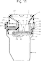
11 ist eine 2 entsprechende vertikale Querschnittansicht, die eine Kraftstoffeinfüllmündung einer dritten Ausführungsform darstellt. 11 is a 2 corresponding vertical cross-sectional view illustrating a fuel filler mouth of a third embodiment.
12 ist eine 4 entsprechende Perspektivansicht, die ein Aussehen eines zweiten Elements darstellt, das die Kraftstoffeinfüllmündung der dritten Ausführungsform aufbaut. Der Einfachheit der Erklärung halber ist ein Zustand dargestellt, in dem eine Absperrung nach unten gedrückt ist und geöffnet ist. 12 is a 4 corresponding perspective view illustrating an appearance of a second element, which builds the fuel filler mouth of the third embodiment. For simplicity of explanation, a state is shown in which a barrier is pushed down and opened.
13 ist ein 5 entsprechender vertikaler Querschnitt, der die Kraftstoffeinfüllmündung der dritten Ausführungsform darstellt, in die ein Kraftstoffeinfüllstutzen eingesetzt ist. Ein Querschnitt entspricht einer Ebene, die in 14 mit Pfeilen C markiert ist. 13 is a 5 corresponding vertical cross-section illustrating the fuel filler neck of the third embodiment, in which a fuel filler neck is inserted. A cross section corresponds to a plane in 14 marked with arrows C.
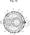
14 ist eine 6 entsprechende querlaufende Querschnittansicht, welche die Kraftstoffeinfüllmündung der dritten Ausführungsform darstellt, in die der Kraftstoffeinfüllstutzen eingesetzt ist. 14 is a 6 corresponding cross-sectional cross-sectional view illustrating the fuel filler mouth of the third embodiment, in which the fuel filler neck is inserted.
15 ist eine 2 entsprechende vertikale Querschnittansicht, die eine Kraftstoffeinfüllmündung einer vierten Ausführungsform darstellt. 15 is a 2 corresponding vertical cross-sectional view illustrating a fuel filler mouth of a fourth embodiment.
16 ist eine 4 entsprechende Perspektivansicht, die ein Aussehen eines zweiten Elements darstellt, das die Kraftstoffeinfüllmündung der vierten Ausführungsform darstellt. Der Einfachheit der Erklärung halber ist ein Zustand dargestellt, in dem die Absperrung nach unten gedrückt ist und geöffnet ist. 16 is a 4 corresponding perspective view illustrating an appearance of a second element, which represents the fuel filler mouth of the fourth embodiment. The simplicity For the sake of explanation, a state is shown in which the barrier is pressed down and is open.
17 ist eine 5 entsprechende vertikale Querschnittansicht, welche die Kraftstoffeinfüllmündung der vierten Ausführungsform darstellt, in die ein Kraftstoffeinfüllstutzen eingesetzt ist. Ein Querschnitt entspricht einer Ebene, die in 18 mit Pfeilen D markiert ist. 17 is a 5 corresponding vertical cross-sectional view illustrating the fuel filler mouth of the fourth embodiment, in which a fuel filler neck is inserted. A cross section corresponds to a plane in 18 marked with arrows D.
18 ist eine 6 entsprechende querlaufende Querschnittansicht, welche die Kraftstoffeinfüllmündung gemäß der vierten Ausführungsform darstellt, in die der Kraftstoffeinfüllstutzen eingesetzt ist. 18 is a 6 corresponding cross-sectional cross-sectional view illustrating the fuel filler port according to the fourth embodiment, in which the fuel filler neck is inserted.
Detaillierte Beschreibunh der bevorzugten AusführungsformDetailed description of the preferred embodiment
Ausführungsformen der vorliegenden Erfindung werden nachstehend unter Bezug auf die Figuren erklärt. Zum Beispiel wird die vorliegende Erfindung auf eine Kraftstoffeinfüllmündung 3 angewendet, welche eine Absperrung 272, wie in 1 bis 18 dargestellt, umfasst. Die Absperrung 272 schließt und öffnet eine zweite Öffnung 277 automatisch. Wenngleich ein Öffnungsrand 3 in 2 und anderen Figuren immer freiliegend ist, kann ein Kappe, die in 2 und anderen nicht dargestellt ist, geeignet sein, zu verhindern, dass Staub in die Kraftstoffeinfüllmündung 3 eintritt. Falls die Kappe angepasst ist, ist eine Gewindenut zum Anschrauben der Kappe auf eine Innenfläche eines trichterförmigen Elements (auf das hier nachstehend als ein Trichter 12 Bezug genommen wird) geschnitten.Embodiments of the present invention will be explained below with reference to the figures. For example, the present invention is directed to a fuel filler throat 3 applied, which is a barrier 272 , as in 1 to 18 represented comprises. The barrier 272 closes and opens a second opening 277 automatically. Although an opening edge 3 in 2 and other figures is always exposed, a cap that can be in 2 and others not shown, be suitable to prevent dust in the fuel filler neck 3 entry. If the cap is fitted, a thread groove for screwing the cap on an inner surface of a funnel-shaped member (hereinafter referred to as a funnel 12 Is taken) cut.
Jede Ausführungsform wird nachstehend beschrieben.Each embodiment will be described below.
Erste Ausführungsform von Fig. 1 bis Fig. 6First embodiment of FIGS. 1 to 6
Ein erstes Element 1 ist ein trichterförmiges Element (Trichter 12) und hat eine erste Öffnung an seinem unteren Ende. Die erste Öffnung 11 ist derart aufgebaut, dass ein Innendurchmesser gleich einem Außendurchmesser eines Kraftstoffeinfüllstutzens 5 ist. Wenn daher der Kraftstoffeinfüllstutzen 5 eingesetzt wird, wie in 5 dargestellt, gibt es kaum eine Lücke zwischen dem Stutzen 5 und der ersten Öffnung 11. Das erste Element 1 hat ein Gehäuse 31. Das Gehäuse 31 hat eine Form, die einen kleinen hohlen Zylinder und einen großen hohlen Zylinder, deren Durchmesser voneinander verschieden sind, in einer stufenweisen Art stapelt. Das Gehäuse 3 hat den Öffnungsrand 311. Der Öffnungsrand 311 ist derart aufgebaut, dass sein Innendurchmesser größer als der Außendurchmesser des Kraftstoffeinfüllstutzens 5 ist. Der Trichter 12 und das Gehäuse 31 können entweder integral geformt sein oder getrennt geformt sein. Falls das Gehäuse 31 und der Trichter 12 getrennt geformt sind, sind das Gehäuse 31 und der Trichter 12 durch Einpassen des oberen Endes des Trichters 12 in einen gewalzten Abschnitt des Öffnungsrands 311 verbunden, so dass der Öffnungsrand 311 des Gehäuses 31 und der obere Rand des Trichters 12 miteinander in Verbindung stehen. Eine Mitte der ersten Öffnung 11 ist, wie in 3 dargestellt, exzentrisch in Bezug auf eine Mitte eines Kreises des Öffnungsrands 311.A first element 1 is a funnel-shaped element (funnel 12 ) and has a first opening at its lower end. The first opening 11 is constructed such that an inner diameter is equal to an outer diameter of a fuel filler neck 5 is. Therefore, if the fuel filler neck 5 is used as in 5 As shown, there is hardly a gap between the neck 5 and the first opening 11 , The first element 1 has a housing 31 , The housing 31 has a shape that stacks a small hollow cylinder and a large hollow cylinder whose diameters are different from each other in a stepwise manner. The housing 3 has the opening edge 311 , The opening edge 311 is constructed such that its inner diameter is larger than the outer diameter of the fuel filler neck 5 is. The funnel 12 and the case 31 may be either integrally molded or formed separately. If the case 31 and the funnel 12 are formed separately, are the housing 31 and the funnel 12 by fitting the upper end of the funnel 12 in a rolled portion of the opening edge 311 connected so that the opening edge 311 of the housing 31 and the top of the funnel 12 communicate with each other. A middle of the first opening 11 is how in 3 represented eccentric with respect to a center of a circle of the opening edge 311 ,
Ein zweites Element 2 umfasst eine untere Platte 27, eine kreisförmige Wand 275, die um die untere Platte 27 herum bereitgestellt ist und gegen einen Endabschnitt 41 der Kraftstoffeinfüllleitung 4 anstößt oder anliegt, wenn das zweite Element 2 in die Kraftstoffeinfüllleitung 4 eingepasst ist, wobei die zweite Öffnung 277 die untere Platte 27 in der vertikalen Richtung durchdringt, eine zylindrische Wand 24 von der unteren Platte 27 vorsteht, um die zweite Öffnung 277 zu umschließen, und eine Vielzahl von Führungsvorsprüngen 21, die in der Umfangsrichtung intermittierend auf einer Umfangsfläche der zylindrischen Wand 24 bereitgestellt ist und einen Raum 22 zum Führen des Kraftstoffeinfüllstutzens 5 zu der Kraftstoffeinfüllleitung bildet. Das zweite Element 2 ist in den Endabschnitt 41 der Kraftstoffeinfüllleitung 4 eingepasst. Die Leitung 4 ist in einer stufenweisen Art vergrößert, um zu verhindern, dass eine Dicke der Leitung 4 lokal verdünnt ist. Wie in 4 dargestellt, hat die zweite Öffnung 277 eine vorstehende Öffnung 271, die radial auswärts vorsteht. Wenn der Kraftstoffeinfüllstutzen 5 durch die zweite Öffnung 277 eingesetzt ist, wird, wie in 5 dargestellt, eine Lücke (die vorstehende Öffnung 271) an der zweiten Öffnung 277, nämlich zwischen dem Kraftstoffeinfüllstutzen 5 und der unteren Platte 27, ausgebildet. Die Lücke erlaubt das Zurückfließen von Kraftstoff, so dass er durch sie hindurch fließt. Das zweite Element 2 ist mit einer Absperrung 272 versehen, die durch eine Torsionsschraubenfeder 272 nach oben vorgespannt ist. Die zweite Öffnung 277 und die vorstehende Öffnung 271 sind, wie in 2 dargestellt, mit der Absperrung 272 verschlossen, wenn der Kraftstoffeinfüllstutzen 5 nicht eingesetzt ist. Die Absperrung 272 wird nach unten gedreht und geöffnet, indem sie, wie in 5 dargestellt, mit dem Kraftstoffeinfüllstutzen 5 gedrückt wird. Um eine Form der vorstehenden Öffnung 271 abzubilden, ist in 4 ein Zustand, in dem die Absperrung 272 nach unten gedrückt und geöffnet ist, dargestellt.A second element 2 includes a lower plate 27 , a circular wall 275 around the lower plate 27 is provided around and against an end portion 41 the fuel fill line 4 abuts or abuts when the second element 2 into the fuel fill line 4 is fitted, with the second opening 277 the lower plate 27 penetrates in the vertical direction, a cylindrical wall 24 from the bottom plate 27 protrudes to the second opening 277 to enclose, and a variety of leadership projections 21 in the circumferential direction intermittently on a peripheral surface of the cylindrical wall 24 is provided and a room 22 for guiding the fuel filler neck 5 forms to the fuel filling line. The second element 2 is in the end section 41 the fuel fill line 4 fitted. The administration 4 is enlarged in a stepwise manner to prevent a thickness of the pipe 4 diluted locally. As in 4 shown, has the second opening 277 a protruding opening 271 projecting radially outward. When the fuel filler neck 5 through the second opening 277 is used, as in 5 shown a gap (the protruding opening 271 ) at the second opening 277 between the fuel filler neck 5 and the lower plate 27 , educated. The gap allows fuel to flow back so that it flows through them. The second element 2 is with a barrier 272 provided by a torsion coil spring 272 is biased upward. The second opening 277 and the opening above 271 are, as in 2 shown with the barrier 272 closed when the fuel filler neck 5 is not used. The barrier 272 is turned down and opened by, as in 5 shown with the fuel filler neck 5 is pressed. Around a shape of the protruding opening 271 to map is in 4 a state in which the barrier 272 pressed down and opened.
Ein Dichtungsring 28 ist auf einem Außenumfang der kreisförmigen Wand 275 des zweiten Elements 2 installiert. Der Dichtungsring 28 dichtet die Kraftstoffeinfüllleitung 4 luftdicht ab, indem er eine Innenwand der Kraftstoffeinfüllleitung 4 eng kontaktiert. Das zweite Element 2 wird in den Endabschnitt 41 der Kraftstoffeinfüllleitung 4 eingepasst, bis das zweite Element 2 vollständig in dem Endabschnitt 41 aufgenommen ist. Das zweite Element 2 ist mit einem Ventil 274 zum Einstellen eines Drucks eines Inneren der Kraftstoffeinfüllleitung 4 in der unmittelbaren Nachbarschaft der zweiten Öffnung 277 versehen. Falls die Kraftstoffeinfüllmündung anstelle der Absperrung 272 an eine Einschraubkappe angepasst ist, kann das Ventil 274 in die Einschraubkappe eingebaut sein.A sealing ring 28 is on an outer circumference of the circular wall 275 of the second element 2 Installed. The sealing ring 28 seals the fuel fill line 4 airtight by placing an inner wall of the fuel fill line 4 closely contacted. The second element 2 will be in the end section 41 the fuel fill line 4 fitted until the second element 2 completely in the end section 41 is included. The second element 2 is with a valve 274 for adjusting a pressure of an interior of the fuel filler pipe 4 in the immediate vicinity of the second opening 277 Mistake. If the fuel filler port instead of the shut-off 272 adapted to a screw-in, the valve can 274 be installed in the screw cap.
Die kreisförmige Wand 275 hat vier Eingreifstücke 276, die ausgebildet sind, indem ihre Wand von einem oberen Rand nach unten an acht Abschnitten geschnitten ist. Die Eingreifstücke 276 greifen mit einer Innenfläche eines unteren zylindrischen Abschnitts des Gehäuses 31 ein. Die Eingreifstücke 276 greifen auch mit dem Endabschnitt 41 ein und bestimmen eine Position des zweiten Elements 2 in Bezug auf die Kraftstoffeinfüllleitung 4, wenn das zweite Element 2 in den Endabschnitt 41 eingepasst ist, da eine Spitze der Eingreifstücke 41 radial auswärts positioniert ist. Das Gehäuse 31 ist wie folgt auf der Kraftstoffeinfüllleitung 4 installiert. Ein oberes Ende des ersten Elements 1 ist in ein Inneres eines gefalteten Abschnitts des Öffnungsendes 311 gefaltet. Der untere zylindrische Abschnitt des Gehäuses 31 ist außen mit dem Endabschnitt 41 montiert, der das zweite Element 2 unterbringt. Ein Raum ist zwischen einer Außenfläche der zylindrischen Wand 24, die auf dem zweiten Element 2 bereitgestellt ist, und einer Innenfläche des Gehäuses 31 ausgebildet. Dieser Raum wirkt vorübergehend als eine Kammer 121 und nimmt den zurückfließenden Kraftstoff auf. Die Kammer 121 steht mit dem Auslass 23 in Verbindung, der, wie nachstehend beschrieben, zwischen den benachbarten Führungsvorsprüngen 21 bereitgestellt ist. Die Kammer 121 ist von dem unteren zylindrischen Abschnitt des Gehäuses 31 umschlossen. Ein zweiter Auslass 312 ist auf dem unteren zylindrischen Abschnitt des Gehäuses 31 ausgebildet. Der zweite Auslass 312 ist ein Durchgangsloch, das die kreisförmige Wand 275 an dem Endabschnitt 41 der Kraftstoffeinfüllleitung 4 durchdringt (4). Die Kammer 121 steht über den zweiten Auslass 312 mit einer Außenseite einer Kraftstoffeinfüllleitung 4 in Verbindung und gibt den zurückfließenden Kraftstoff dadurch ab.The circular wall 275 has four intervening pieces 276 formed by cutting its wall from an upper edge down to eight sections. The intervention pieces 276 engage with an inner surface of a lower cylindrical portion of the housing 31 one. The intervention pieces 276 also engage with the end section 41 and determine a position of the second element 2 with respect to the fuel fill line 4 if the second element 2 in the end section 41 is fitted as a tip of the engaging pieces 41 is positioned radially outward. The housing 31 is as follows on the fuel fill line 4 Installed. An upper end of the first element 1 is in an interior of a folded portion of the opening end 311 folded. The lower cylindrical section of the housing 31 is outside with the end section 41 mounted, which is the second element 2 houses. A space is between an outer surface of the cylindrical wall 24 that on the second element 2 is provided, and an inner surface of the housing 31 educated. This room temporarily acts as a chamber 121 and picks up the returning fuel. The chamber 121 stands with the outlet 23 which, as described below, between the adjacent guide projections 21 is provided. The chamber 121 is from the lower cylindrical portion of the housing 31 enclosed. A second outlet 312 is on the lower cylindrical section of the housing 31 educated. The second outlet 312 is a through hole that is the circular wall 275 at the end portion 41 the fuel fill line 4 penetrates ( 4 ). The chamber 121 stands over the second outlet 312 with an outside of a fuel filler pipe 4 and thereby releases the returning fuel.
Das zweite Element 2 der ersten Ausführungsform hat eine zylindrische Wand 24, deren Innendurchmesser größer als ein Außendurchmesser eines Kraftstoffeinfüllstutzens 5 ist. Die zylindrische Wand 24 steht von einer unteren Platte 27 vor, so dass die zylindrische Wand 24 die zweite Öffnung 277 umschließt. Die zylindrische Wand 24 ist mit der Vielzahl von Führungsvorsprüngen 21 versehen, die von seiner Umfangsfläche radial einwärts vorstehen. Die Führungsvorsprünge 21 sind in einer Umfangsrichtung der zylindrischen Wand 24 intermittierend und länglich parallel zu einer Einsetzrichtung des Kraftstoffeinfüllstutzens 5 bereitgestellt. Die zylindrische Wand 24, die nicht mit den Führungsvorsprüngen 21 versehen ist, ist der Auslass 23. Mit anderen Worten ist der Auslass 23 eine Teilöffnung, die sich, wie in 4 dargestellt, von einem oberen Ende der zylindrischen Wand 24 erstreckt. Ein Raum wird zwischen den benachbarten Führungsvorsprüngen 21 ausgebildet, wenn der Kraftstoffeinfüllstutzen 5 eingesetzt ist. Dieser Raum wirkt als ein Pufferraum.The second element 2 The first embodiment has a cylindrical wall 24 whose inner diameter is larger than an outer diameter of a fuel filler neck 5 is. The cylindrical wall 24 is from a lower plate 27 before, so that the cylindrical wall 24 the second opening 277 encloses. The cylindrical wall 24 is with the multitude of leadership projections 21 provided which project radially inwardly from its peripheral surface. The guide projections 21 are in a circumferential direction of the cylindrical wall 24 intermittently and longitudinally parallel to an insertion direction of the fuel filler neck 5 provided. The cylindrical wall 24 not with the guide tabs 21 is provided, is the outlet 23 , In other words, the outlet 23 a partial opening, which, as in 4 shown from an upper end of the cylindrical wall 24 extends. A space becomes between the adjacent guide projections 21 formed when the fuel filler neck 5 is used. This space acts as a buffer space.
Der von dem Öffnungsrand 311 eingesetzte Kraftstoffeinfüllstutzen 5 geht durch die erste Öffnung 11, einen Raum, der von den Führungsvorsprüngen 21 umschlossen wird, und die zweite Öffnung. Die Absperrung 272 wird gedrückt und nach unten geöffnet, wobei ein Ende des Kraftstoffeinfüllstutzens 5 die Spitze des Kraftstoffeinfüllstutzens 5 in die Kraftstoffeinfüllleitung 4 einsetzen soll. Das erste Element 1 ist derart aufgebaut, dass ein Innendurchmesser der ersten Öffnung 11 gleich einem Außendurchmesser des Kraftstoffeinfüllstutzens 5 ist. Ein Abstand zwischen entgegengesetzten Innenoberflächen der Führungsvorsprünge 21 ist ebenfalls gleich dem Außendurchmesser des Kraftstoffeinfüllstutzens 5 gemacht. Daher wird der Kraftstoffeinfüllstutzen 5 sicher zu der zweiten Öffnung 277 geführt, indem er durch die erste Öffnung 11 und die Führungsvorsprünge 21 geführt wird. Ferner stößt der Kraftstoffeinfüllstutzen 5 während des Nachtankens nicht an, da der Kraftstoffeinfüllstutzen 5 von der ersten Öffnung und den Führungsvorsprüngen 21 sicher gehalten wird. Daher wird ein Innenumfangsrand der zweiten Öffnung 277, der als eine Dichtungsoberfläche wirkt, von dem Kraftstoffeinfüllstutzen 5 nicht beschädigt.The one from the opening edge 311 used fuel filler neck 5 goes through the first opening 11 , a space created by the guide tabs 21 is enclosed, and the second opening. The barrier 272 is pressed and opened down, with one end of the fuel filler neck 5 the tip of the fuel filler neck 5 into the fuel fill line 4 should use. The first element 1 is constructed such that an inner diameter of the first opening 11 equal to an outer diameter of the fuel filler neck 5 is. A distance between opposite inner surfaces of the guide projections 21 is also equal to the outside diameter of the fuel filler neck 5 made. Therefore, the fuel filler neck becomes 5 safely to the second opening 277 guided by passing through the first opening 11 and the guide projections 21 to be led. Furthermore, the fuel filler neck abuts 5 during refueling not on, as the fuel filler neck 5 from the first opening and the guide projections 21 is held securely. Therefore, an inner peripheral edge of the second opening becomes 277 acting as a sealing surface of the fuel filler neck 5 not damaged.
Da der Innendurchmesser der ersten Öffnung 11 und der Abstand zwischen entgegengesetzten Führungsvorsprüngen 21 dicht an dem Außendurchmesser des Kraftstoffeinfüllstutzens 5 sind, steigt ein Druck des zurückfließenden Kraftstoffs 6 nahe der ersten Öffnung 11 und den Führungsvorsprüngen 21. Der Auslass 23 ist zwischen den in der Umfangsrichtung der zylindrischen Wand 24 benachbarten Führungsvorsprüngen bereitgestellt. Wie in 5 und 6 dargestellt, entweicht der zurückfließende Kraftstoff 6 und fließt über den Auslass 23 in die Kammer 121, da der zurückfließende Kraftstoff kaum zwischen dem Kraftstoffeinfüllstutzen 5 und der ersten Öffnung 11 und zwischen dem Kraftstoffeinfüllstutzen 5 und einer Innenfläche des Führungsvorsprungs 21, wo der Druck hoch wird, fließt. Der zurückfließende Kraftstoff 6 fließt über die vorstehende Öffnung 271 und den Auslass 23 in die Kammer 121. Der zurückfließende Kraftstoff 6 wird aus der Kammer 121 über den zweiten Auslass 121 nach außerhalb der Kraftstoffeinfüllleitung 4 abgegeben. Daher läuft der zurückfließende Kraftstoff 6 gemäß der Kraftstoffeinfüllmündung 3 der ersten Ausführungsform nicht aus dem Öffnungsende 31 über.As the inner diameter of the first opening 11 and the distance between opposing guide protrusions 21 close to the outside diameter of the fuel filler neck 5 are a pressure of the recirculating fuel increases 6 near the first opening 11 and the guide tabs 21 , The outlet 23 is between the in the circumferential direction of the cylindrical wall 24 provided adjacent guide projections. As in 5 and 6 shown escapes the returning fuel 6 and flows over the outlet 23 in the chamber 121 because the returning fuel barely between the fuel filler neck 5 and the first opening 11 and between the fuel filler neck 5 and an inner surface of the guide projection 21 where the pressure is high flows. The returning fuel 6 flows over the protruding opening 271 and the outlet 23 in the chamber 121 , The returning fuel 6 gets out of the chamber 121 over the second outlet 121 to the outside of the fuel line 4 issued. Therefore, the returning fuel runs 6 according to the fuel filler mouth 3 the first embodiment not from the opening end 31 above.
Der einmal in die Kammer 121 fließende Kraftstoff fließt möglicherweise über den Auslass 23 zu dem Raum 22 zurück, der von der Vielzahl von Führungsvorsprüngen 21 umschlossen ist. Um dies zu verhindern, ist, wie mit einer gestrichelten Linie in 6 dargestellt, vorzugsweise ein Flussänderungsblock 273 an einer radialen Außenseite des Auslasses 23 bereitgestellt. Der Flussänderungsblock 273 stößt mit dem Kraftstoff 6 zusammen, der durch den Auslass 23 ausströmt, und ändert die Richtung in eine Umfangsrichtung. Ein Flussänderungsblock 273, der in 6 beispielhaft dargestellt ist, ist eine Platte, die entlang eines Umfangs eines Kreises gelegt ist, der größer als die zylindrische Wand 24 ist und die gleiche Mitte wie die zylindrische Wand 24 hat. Da der Flussänderungsblock 273 derart bereitgestellt ist, dass er dem Auslass 23 gegenüber liegt, baut der Flussänderungsblock 273 eine Art von Labyrinth auf. Der Flussänderungsblock 273 führt den Kraftstoff 6, der durch den Auslass 23 zu dem zweiten Auslass 312 ausfließt, und verhindert, dass der Kraftstoff 6 zurück in den Raum 22 fließt, während der vorbeischießende Kraftstoff geschwächt wird. The once in the chamber 121 flowing fuel may flow through the outlet 23 to the room 22 back, that of the variety of leadership tabs 21 is enclosed. To prevent this is, as with a dashed line in 6 illustrated, preferably a Flußänderungsblock 273 at a radial outside of the outlet 23 provided. The flow change block 273 bumps with the fuel 6 together, through the outlet 23 flows out, and changes the direction in a circumferential direction. A flow change block 273 who in 6 is exemplified, is a plate which is placed along a circumference of a circle which is larger than the cylindrical wall 24 is and the same center as the cylindrical wall 24 Has. Because the flow change block 273 is provided such that it is the outlet 23 is opposite, builds the flow change block 273 a kind of labyrinth on. The flow change block 273 leads the fuel 6 passing through the outlet 23 to the second outlet 312 flows out, and prevents the fuel 6 back to the room 22 flows while the passing fuel is weakened.
Eine in 7 bis 10 dargestellte zweite Ausführungsform, eine in 11 bis 14 dargestellte dritte Ausführungsform und eine in 15 bis 18 dargestellte Ausführungsform unterscheiden sich in einem Aufbau der Führungsvorsprünge 21. Jedoch sind diese Ausführungsformen in der Hinsicht, dass der zurückfließende Kraftstoff 6 ebenfalls zu dem Auslass 23 geführt wird und von dem zweiten Auslass 312 nach außerhalb der Kraftstoffeinfüllleitung 4 geleitet wird, die gleichen wie in der ersten Ausführungsform. Der Kraftstoff 6 wird zu dem Auslass 23 geleitet, indem der Druck des Kraftstoffs, der die Lücke zwischen der ersten Öffnung 11 und dem Kraftstoffeinfüllstutzen 5 und auch zwischen dem Führungsvorsprung 21 und dem Kraftstoffeinfüllstutzen 5 durchläuft, erhöht wird. Mit anderen Worten unterscheidet sich jede Ausführungsform nur in einem Aufbau des zweiten Elements 2 und unterscheidet sich nicht in einem Aufbau des ersten Elements 1, des Gehäuses 31 und des Endabschnitts 41 der Leitung 4, wie in 2, 7, 11 und 15 dargestellt. Daher sind die jeweiligen zweiten Elemente mit jeweiligen Ausführungsformen kompatibel und dazwischen austauschbar.An in 7 to 10 illustrated second embodiment, an in 11 to 14 illustrated third embodiment and an in 15 to 18 illustrated embodiment differ in a structure of the guide projections 21 , However, these embodiments are in the sense that the returning fuel 6 also to the outlet 23 is guided and from the second outlet 312 to the outside of the fuel line 4 are passed, the same as in the first embodiment. The fuel 6 becomes the outlet 23 passed by the pressure of the fuel, which closes the gap between the first opening 11 and the fuel filler neck 5 and also between the leadership lead 21 and the fuel filler neck 5 goes through, is increased. In other words, each embodiment differs only in a structure of the second element 2 and does not differ in a construction of the first element 1 , of the housing 31 and the end section 41 the line 4 , as in 2 . 7 . 11 and 15 shown. Therefore, the respective second elements are compatible with respective embodiments and interchangeable therebetween.
Zweite Ausführungsform von Fig. 7 bis Fig. 10Second embodiment of FIGS. 7 to 10
Ein zweites Element 2 der zweiten Ausführungsform hat, wie in 7 und 8 dargestellt, eine zylindrische Wand 24, deren Innendurchmesser gleich dem Außendurchmesser des Kraftstoffeinfüllstutzens 5 ist. Ein Auslass 23 ist auf der zylindrischen Wand 24 bereitgestellt. Eine restliche zylindrische Wand 24, die nicht mit dem Kraftstoffauslass 23 versehen ist, ist ein Führungsvorsprung 21. Wie in 8 dargestellt, hat die zylindrische Wand 24 eine Form, so dass eine Umfangsfläche, abgesehen von einem Bereich, in dem der Führungsvorsprung 21 bereitgestellt ist, vollkommen entfernt ist. Der Kraftstoffeinfüllstutzen 5 ist in einen Raum eingesetzt, der von den Führungsvorsprüngen 21 umschlossen ist. Eine kreisförmige Rippe 211 ist auf einer unteren Platte 27 bereitgestellt, welche die zweite Öffnung 277 umgibt, um einen Umfang der zweiten Öffnung 277 zu verstärken. Die zweite Öffnung 277 erfordert als die Ventilschicht bzw. -blatt für die Absperrung 272 und eine Grundlage zum Halten der Führungsvorsprünge 21 eine mechanische Festigkeit. Da alles der zylindrischen Wand 24, abgesehen von einem Bereich, in dem der Führungsvorsprung 21 bereitgestellt ist, entfernt ist, wird der Pufferraum, der zwischen dem Kraftstoffeinfüllstutzen 5 und der zylindrischen Wand 24 in der ersten Ausführungsform bereitgestellt ist, in der zweiten Ausführungsform nicht um den Kraftstoffeinfüllstutzen 5 herum bereitgestellt. Da der Innendurchmesser der zylindrischen Wand 24 kleiner gemacht ist, kann das zweite Element 2 in der zweiten Ausführungsform verkleinert werden. Eine Lücke wird zwischen der unteren Platte 27 und dem Kraftstoffeinfüllstutzen 5 ausgebildet, wenn der Kraftstoffeinfüllstutzen, wie in 9 dargestellt, in die zweite Öffnung 277 eingesetzt wird. Die Lücke wird ebenso wie in der ersten Ausführungsform als eine vorstehende Öffnung 271 bezeichnet. Um eine Form der vorstehenden Öffnung 271 deutlich abzubilden, ist in 8 ein Zustand abgebildet, in dem die Absperrung 272 nach unten gedrückt ist und geöffnet ist.A second element 2 of the second embodiment has, as in 7 and 8th shown, a cylindrical wall 24 whose inner diameter is equal to the outer diameter of the fuel filler neck 5 is. An outlet 23 is on the cylindrical wall 24 provided. A remaining cylindrical wall 24 not with the fuel outlet 23 is provided, is a guide projection 21 , As in 8th shown, has the cylindrical wall 24 a shape such that a peripheral surface, apart from an area in which the guide projection 21 is completely removed. The fuel filler neck 5 is inserted in a space that is separated from the guide projections 21 is enclosed. A circular rib 211 is on a lower plate 27 provided, which the second opening 277 surrounds to a perimeter of the second opening 277 to reinforce. The second opening 277 required as the valve layer or sheet for the barrier 272 and a foundation for holding the guide projections 21 a mechanical strength. Since everything is the cylindrical wall 24 except for an area where the leadership tab 21 is provided, the buffer space is between the fuel filler neck 5 and the cylindrical wall 24 in the first embodiment, in the second embodiment, not around the fuel filler neck 5 provided around. As the inner diameter of the cylindrical wall 24 made smaller, the second element can 2 be reduced in the second embodiment. A gap will be between the bottom plate 27 and the fuel filler neck 5 formed when the fuel filler neck, as in 9 shown in the second opening 277 is used. The gap becomes a protruding opening as in the first embodiment 271 designated. Around a shape of the protruding opening 271 clearly depict is in 8th a state pictured in which the barrier 272 pressed down and is open.
Ein Innendurchmesser der ersten Öffnung 11 und ein Abstand zwischen den entgegengesetzten Führungsvorsprüngen 21 ist in der zweiten Ausführungsform ebenso wie in der ersten Ausführungsform nahe an dem Außendurchmesser des Kraftstoffeinfüllstutzens 5. Daher entweicht der zurückfließende Kraftstoff 6, wie in 9 und 10 dargestellt, und fließt über den Auslass 23 in die Kammer 121, da der zurückfließende Kraftstoff kaum zwischen dem Kraftstoffeinfüllstutzen 5 und der ersten Öffnung 11 und zwischen dem Kraftstoffeinfüllstutzen 5 und einer Innenfläche des Führungsvorsprungs 21, wo der Druck hoch wird, fließt. Der zurückfließende Kraftstoff 6 fließt über die vorstehende Öffnung 271 und den Auslass 23 in die Kammer 121. Der zurückfließende Kraftstoff 6 wird aus der Kammer 121 über den zweiten Auslass 121 nach außerhalb der Kraftstoffeinfüllleitung 4 geleitet. Daher läuft der zurückfließende Kraftstoff 6 gemäß der Kraftstoffeinfüllmündung 3 der zweiten Ausführungsform nicht von dem Öffnungsende 31 über.An inner diameter of the first opening 11 and a distance between the opposing guide protrusions 21 In the second embodiment, as in the first embodiment, it is close to the outer diameter of the fuel filler neck 5 , Therefore, the returning fuel escapes 6 , as in 9 and 10 shown, and flows over the outlet 23 in the chamber 121 because the returning fuel barely between the fuel filler neck 5 and the first opening 11 and between the fuel filler neck 5 and an inner surface of the guide projection 21 where the pressure is high flows. The returning fuel 6 flows over the protruding opening 271 and the outlet 23 in the chamber 121 , The returning fuel 6 gets out of the chamber 121 over the second outlet 121 to the outside of the fuel line 4 directed. Therefore, the returning fuel runs 6 according to the fuel filler mouth 3 of the second embodiment not from the opening end 31 above.
Dritte Ausführungsform von Fig. 11 bis Fig. 14Third embodiment of FIGS. 11 to 14
Ein zweites Element 2 der dritten Ausführungsform hat, wie in 11 und 12 dargestellt, eine zylindrische Wand 24, deren Innendurchmesser gleich dem Außendurchmesser des Kraftstoffeinfüllstutzens 5 ist. Ein Auslass 23 ist auf der zylindrischen Wand 24 bereitgestellt. Eine restliche zylindrische Wand 24, die nicht mit dem Kraftstoffauslass 23 versehen ist, ist ein Führungsvorsprung 21. Der Kraftstoffeinfüllstutzen 5 ist in einen Raum 22 eingesetzt, der von den Führungsvorsprüngen 21 umschlossen ist. Da eine Umfangsfläche der Führungselemente 21 in einer Umfangsrichtung lang ist, hat ein Umfang der zweiten Öffnung 277 eine ausreichende mechanische Festigkeit. Daher ist es nicht notwendig wie im Fall der zweiten Ausführungsform (siehe 8) irgendeine kreisförmige Rippe 211 um einen Umfang der zweiten Öffnung 271 bereitzustellen. Die zweite Ausführungsform und die dritte Ausführungsform sind in dieser Hinsicht verschieden. Da der Innendurchmesser der zylindrischen Wand 24 kleiner gemacht ist, kann das zweite Element 2 in der dritten Ausführungsform ebenfalls verkleinert werden. Eine Lücke wird zwischen der unteren Platte 27 und dem Kraftstoffeinfüllstutzen 5 ausgebildet, wenn der Kraftstoffeinfüllstutzen, wie in 13 dargestellt, in die zweite Öffnung 277 eingesetzt wird. Die Lücke wird ebenso wie in der ersten Ausführungsform als eine vorstehende Öffnung 271 bezeichnet.A second element 2 of the third embodiment has, as in 11 and 12 shown, a cylindrical wall 24 whose inner diameter is equal to the outer diameter of the fuel filler 5 is. An outlet 23 is on the cylindrical wall 24 provided. A remaining cylindrical wall 24 not with the fuel outlet 23 is provided, is a guide projection 21 , The fuel filler neck 5 is in a room 22 used by the guide tabs 21 is enclosed. As a peripheral surface of the guide elements 21 in a circumferential direction has a circumference of the second opening 277 sufficient mechanical strength. Therefore, it is not necessary as in the case of the second embodiment (see 8th ) any circular rib 211 around a perimeter of the second opening 271 provide. The second embodiment and the third embodiment are different in this respect. As the inner diameter of the cylindrical wall 24 made smaller, the second element can 2 are also reduced in the third embodiment. A gap will be between the bottom plate 27 and the fuel filler neck 5 formed when the fuel filler neck, as in 13 shown in the second opening 277 is used. The gap becomes a protruding opening as in the first embodiment 271 designated.
Ein Innendurchmesser der ersten Öffnung 11 und ein Abstand zwischen den entgegengesetzten Führungsvorsprüngen 21 ist in der dritten Ausführungsform ebenso wie in der ersten Ausführungsform nahe an dem Außendurchmesser des Kraftstoffeinfüllstutzens 5. Daher entweicht der zurückfließende Kraftstoff 6, wie in 13 und 14 dargestellt, und fließt über den Auslass 23 in die Kammer 121, da der zurückfließende Kraftstoff kaum zwischen dem Kraftstoffeinfüllstutzen 5 und der ersten Öffnung 11 und zwischen dem Kraftstoffeinfüllstutzen 5 und einer Innenfläche des Führungsvorsprungs 21, wo der Druck hoch wird, fließt. Der zurückfließende Kraftstoff 6 fließt über die vorstehende Öffnung 271 und den Auslass 23 in die Kammer 121. Der zurückfließende Kraftstoff 6 wird aus der Kammer 121 über den zweiten Auslass 121 nach außerhalb der Kraftstoffeinfüllleitung 4 geleitet. Daher läuft der zurückfließende Kraftstoff 6 gemäß der Kraftstoffeinfüllmündung 3 der zweiten Ausführungsform nicht von dem Öffnungsende 31 über. Der Zustand, in dem die Absperrung 272 nach unten gedrückt ist und geöffnet ist, ist der Einfachheit der Erklärung halber in 12 dargestellt.An inner diameter of the first opening 11 and a distance between the opposing guide protrusions 21 In the third embodiment, as in the first embodiment, it is close to the outer diameter of the fuel filler neck 5 , Therefore, the returning fuel escapes 6 , as in 13 and 14 shown, and flows over the outlet 23 in the chamber 121 because the returning fuel barely between the fuel filler neck 5 and the first opening 11 and between the fuel filler neck 5 and an inner surface of the guide projection 21 where the pressure is high flows. The returning fuel 6 flows over the protruding opening 271 and the outlet 23 in the chamber 121 , The returning fuel 6 gets out of the chamber 121 over the second outlet 121 to the outside of the fuel line 4 directed. Therefore, the returning fuel runs 6 according to the fuel filler mouth 3 of the second embodiment not from the opening end 31 above. The state in which the barrier 272 is pressed down and open, the simplicity of explanation is in 12 shown.
Vierte Ausführungsform von Fig. 15 bis Fig. 18Fourth embodiment of FIGS. 15 to 18
Ein zweites Element 2 einer vierten Ausführungsform hat eine Vielzahl von vorstehenden Umfangsflächen 25 und eine Vielzahl von konkaven Umfangsflächen 26. Die vorstehenden Umfangsflächen 25 und die konkaven Umfangsflächen 26 werden in einer Umfangsrichtung der zweiten Öffnung 277 abwechselnd kombiniert und ausgerichtet. Die Innenfläche der vorstehenden Umfangsfläche 25 ist ein Führungsvorsprung 21. Der Kraftstoffeinfüllstutzen 5 wird in einen Raum 22 eingesetzt, der von den Führungsvorsprüngen 21 umschlossen ist. Der Kraftstoff Der Auskleidungsabstand zwischen den entgegengesetzten konkaven Umfangsflächen 26 ist größer als der Außendurchmesser des Kraftstoffeinfüllstutzens 5 und ein Außendurchmesser eines unteren Endes des ersten Elements 1. Der Außendurchmesser des unteren Endes des ersten Elements 1 ist mit einer gestrichelten Linie auf der Außenseite in 18 angezeigt. Da ein Umfang der konkaven Umfangsflächen 26 radial auswärts nach oben geneigt ist, und der Auskleidungsabstand zwischen den entgegengesetzten konkaven Umfangsflächen 26 größer als der Außendurchmesser des unteren Endes des ersten Elements 1, d. h. ein Außendurchmesser des unteren Endes des Trichters 12 ist, wird die Lücke an einem oberen Ende der konkaven Umfangsfläche 26 gebildet. Diese Lücke wirkt als ein Auslass 23, der den zurückfließenden Kraftstoff 6 abgibt. Wenngleich die konkave Umfangsfläche 26 in einem Beispiel von 16 einen Schlitz 28 hat, der auch als der Auslass 23 wirkt, kann der Schlitz 28 weggelassen werden, da die Lücke an dem oberen Ende der konkaven Umfangsfläche 26 bereitgestellt ist. Eine Lücke, die sich von der vorstehend erwähnten Lücke an dem oberen Ende der konkaven Umfangsfläche 26 unterscheidet, wird zwischen der unteren Platte 27 und dem Kraftstoffeinfüllstutzen 5 ausgebildet, wenn der Kraftstoffeinfüllstutzen, wie in 17 dargestellt, in die zweite Öffnung 277 eingesetzt wird. Die Lücke wird ebenso wie in der ersten Ausführungsform als eine vorstehende Öffnung 271 bezeichnet.A second element 2 A fourth embodiment has a plurality of projecting peripheral surfaces 25 and a plurality of concave peripheral surfaces 26 , The protruding peripheral surfaces 25 and the concave peripheral surfaces 26 be in a circumferential direction of the second opening 277 alternately combined and aligned. The inner surface of the protruding peripheral surface 25 is a leadership advantage 21 , The fuel filler neck 5 will be in a room 22 used by the guide tabs 21 is enclosed. The fuel The lining clearance between the opposite concave peripheral surfaces 26 is larger than the outer diameter of the fuel filler neck 5 and an outer diameter of a lower end of the first member 1 , The outer diameter of the lower end of the first element 1 is with a dashed line on the outside in 18 displayed. As a circumference of the concave peripheral surfaces 26 is inclined radially outwardly upwards, and the lining spacing between the opposite concave peripheral surfaces 26 larger than the outer diameter of the lower end of the first member 1 ie, an outer diameter of the lower end of the funnel 12 is, the gap is at an upper end of the concave peripheral surface 26 educated. This gap acts as an outlet 23 that is the returning fuel 6 emits. Although the concave peripheral surface 26 in an example of 16 a slot 28 has, as well as the outlet 23 works, the slot can 28 be omitted, since the gap at the upper end of the concave peripheral surface 26 is provided. A gap extending from the aforementioned gap at the upper end of the concave peripheral surface 26 is different, between the lower plate 27 and the fuel filler neck 5 formed when the fuel filler neck, as in 17 shown in the second opening 277 is used. The gap becomes a protruding opening as in the first embodiment 271 designated.
Ein Innendurchmesser der ersten Öffnung 11 und ein Abstand zwischen den entgegengesetzten Führungsvorsprüngen 21 ist in der vierten Ausführungsform ebenso wie in der ersten Ausführungsform nahe an dem Außendurchmesser des Kraftstoffeinfüllstutzens 5. Daher entweicht der zurückfließende Kraftstoff 6, wie in 17 und 18 dargestellt, und fließt über den Auslass 23 in die Kammer 121, da der zurückfließende Kraftstoff kaum zwischen dem Kraftstoffeinfüllstutzen 5 und der ersten Öffnung 11 und zwischen dem Kraftstoffeinfüllstutzen 5 und einer Innenfläche des Führungsvorsprungs 21, wo der Druck hoch wird, fließt. Der zurückfließende Kraftstoff 6 fließt über die vorstehende Öffnung 271 und den Auslass 23 in die Kammer 121. Der zurückfließende Kraftstoff 6 wird aus der Kammer 121 über den zweiten Auslass 121 nach außerhalb der Kraftstoffeinfüllleitung 4 geleitet. Daher läuft der zurückfließende Kraftstoff 6 gemäß der Kraftstoffeinfüllmündung 3 der vierten Ausführungsform nicht von dem Öffnungsende 31 über. Der Einfachheit der Erklärung halber ist der Zustand der Absperrung 272, die nach unten gedrückt ist und geöffnet ist, abgebildet.An inner diameter of the first opening 11 and a distance between the opposing guide protrusions 21 In the fourth embodiment, as in the first embodiment, it is close to the outer diameter of the fuel filler neck 5 , Therefore, the returning fuel escapes 6 , as in 17 and 18 shown, and flows over the outlet 23 in the chamber 121 because the returning fuel barely between the fuel filler neck 5 and the first opening 11 and between the fuel filler neck 5 and an inner surface of the guide projection 21 where the pressure is high flows. The returning fuel 6 flows over the protruding opening 271 and the outlet 23 in the chamber 121 , The returning fuel 6 gets out of the chamber 121 over the second outlet 121 to the outside of the fuel line 4 directed. Therefore, the returning fuel runs 6 according to the fuel filler mouth 3 the fourth embodiment not from the opening end 31 above. For simplicity of explanation, the state of the barrier 272 , which is pressed down and open, pictured.
ZITATE ENTHALTEN IN DER BESCHREIBUNG QUOTES INCLUDE IN THE DESCRIPTION
Diese Liste der vom Anmelder aufgeführten Dokumente wurde automatisiert erzeugt und ist ausschließlich zur besseren Information des Lesers aufgenommen. Die Liste ist nicht Bestandteil der deutschen Patent- bzw. Gebrauchsmusteranmeldung. Das DPMA übernimmt keinerlei Haftung für etwaige Fehler oder Auslassungen.This list of the documents listed by the applicant has been generated automatically and is included solely for the better information of the reader. The list is not part of the German patent or utility model application. The DPMA assumes no liability for any errors or omissions.
Zitierte PatentliteraturCited patent literature
-
WO 2010/029989 A1 [0003, 0003, 0004, 0005] WO 2010/029989 A1 [0003, 0003, 0004, 0005]