DE102012015942A1 - Process for the preparation of chemical-mechanical polishing layers - Google Patents
Process for the preparation of chemical-mechanical polishing layers Download PDFInfo
- Publication number
- DE102012015942A1 DE102012015942A1 DE102012015942A DE102012015942A DE102012015942A1 DE 102012015942 A1 DE102012015942 A1 DE 102012015942A1 DE 102012015942 A DE102012015942 A DE 102012015942A DE 102012015942 A DE102012015942 A DE 102012015942A DE 102012015942 A1 DE102012015942 A1 DE 102012015942A1
- Authority
- DE
- Germany
- Prior art keywords
- mold cavity
- axis
- area
- section
- cross
- Prior art date
- Legal status (The legal status is an assumption and is not a legal conclusion. Google has not performed a legal analysis and makes no representation as to the accuracy of the status listed.)
- Withdrawn
Links
Images


Classifications
-
- B—PERFORMING OPERATIONS; TRANSPORTING
- B24—GRINDING; POLISHING
- B24D—TOOLS FOR GRINDING, BUFFING OR SHARPENING
- B24D18/00—Manufacture of grinding tools or other grinding devices, e.g. wheels, not otherwise provided for
- B24D18/0009—Manufacture of grinding tools or other grinding devices, e.g. wheels, not otherwise provided for using moulds or presses
-
- H—ELECTRICITY
- H01—ELECTRIC ELEMENTS
- H01L—SEMICONDUCTOR DEVICES NOT COVERED BY CLASS H10
- H01L21/00—Processes or apparatus adapted for the manufacture or treatment of semiconductor or solid state devices or of parts thereof
- H01L21/02—Manufacture or treatment of semiconductor devices or of parts thereof
- H01L21/04—Manufacture or treatment of semiconductor devices or of parts thereof the devices having at least one potential-jump barrier or surface barrier, e.g. PN junction, depletion layer or carrier concentration layer
- H01L21/18—Manufacture or treatment of semiconductor devices or of parts thereof the devices having at least one potential-jump barrier or surface barrier, e.g. PN junction, depletion layer or carrier concentration layer the devices having semiconductor bodies comprising elements of Group IV of the Periodic System or AIIIBV compounds with or without impurities, e.g. doping materials
- H01L21/30—Treatment of semiconductor bodies using processes or apparatus not provided for in groups H01L21/20 - H01L21/26
- H01L21/302—Treatment of semiconductor bodies using processes or apparatus not provided for in groups H01L21/20 - H01L21/26 to change their surface-physical characteristics or shape, e.g. etching, polishing, cutting
- H01L21/304—Mechanical treatment, e.g. grinding, polishing, cutting
-
- B—PERFORMING OPERATIONS; TRANSPORTING
- B24—GRINDING; POLISHING
- B24B—MACHINES, DEVICES, OR PROCESSES FOR GRINDING OR POLISHING; DRESSING OR CONDITIONING OF ABRADING SURFACES; FEEDING OF GRINDING, POLISHING, OR LAPPING AGENTS
- B24B37/00—Lapping machines or devices; Accessories
- B24B37/04—Lapping machines or devices; Accessories designed for working plane surfaces
-
- B—PERFORMING OPERATIONS; TRANSPORTING
- B24—GRINDING; POLISHING
- B24B—MACHINES, DEVICES, OR PROCESSES FOR GRINDING OR POLISHING; DRESSING OR CONDITIONING OF ABRADING SURFACES; FEEDING OF GRINDING, POLISHING, OR LAPPING AGENTS
- B24B37/00—Lapping machines or devices; Accessories
- B24B37/11—Lapping tools
- B24B37/20—Lapping pads for working plane surfaces
- B24B37/24—Lapping pads for working plane surfaces characterised by the composition or properties of the pad materials
Abstract
Es wird ein Verfahren zur Herstellung von Polierschichten zur Verwendung in chemisch-mechanischen Polierkissen bereitgestellt, bei dem die Bildung von Dichtedefekten in den Polierschichten minimiert wird.There is provided a method of making polishing layers for use in chemical mechanical polishing pads wherein the formation of density defects in the polishing layers is minimized.
Description
Die vorliegende Erfindung betrifft allgemein das Gebiet der Herstellung von Polierschichten. Insbesondere betrifft die vorliegende Erfindung ein Verfahren zur Herstellung von Polierschichten zur Verwendung in chemisch-mechanischen Polierkissen.The present invention relates generally to the field of making polishing layers. More particularly, the present invention relates to a method of making polishing layers for use in chemical mechanical polishing pads.
Bei der Herstellung von integrierten Schaltungen und anderen elektronischen Vorrichtungen werden mehrere Schichten von leitenden, halbleitenden und dielektrischen Materialien auf einer Oberfläche eines Halbleiterwafers abgeschieden oder davon entfernt. Dünne Schichten von leitenden, halbleitenden und dielektrischen Materialien können durch eine Anzahl von Abscheidungstechniken abgeschieden werden. Übliche Abscheidungstechniken bei einer modernen Verarbeitung umfassen eine physikalische Gasphasenabscheidung (PVD), die auch als Sputtern bekannt ist, eine chemische Gasphasenabscheidung (CVD), eine plasmaunterstützte chemische Gasphasenabscheidung (PECVD) und ein elektrochemisches Plattieren (ECP).In the fabrication of integrated circuits and other electronic devices, multiple layers of conductive, semiconducting, and dielectric materials are deposited on or removed from a surface of a semiconductor wafer. Thin layers of conductive, semiconducting and dielectric materials may be deposited by a number of deposition techniques. Conventional deposition techniques in modern processing include physical vapor deposition (PVD), also known as sputtering, chemical vapor deposition (CVD), plasma assisted chemical vapor deposition (PECVD) and electrochemical plating (ECP).
Da Schichten von Materialien nacheinander abgeschieden und entfernt werden, wird die oberste Oberfläche des Wafers uneben. Da eine nachfolgende Halbleiterverarbeitung (z. B. eine Metallisierung) erfordert, dass der Wafer eine flache Oberfläche aufweist, muss der Wafer planarisiert werden. Eine Planarisierung ist zur Entfernung einer unerwünschten Oberflächentopographie und von Oberflächendefekten, wie z. B. von rauen Oberflächen, agglomerierten Materialien, Kristallgitterbeschädigungen, Kratzern und verunreinigten Schichten oder Materialien, geeignet.As layers of materials are sequentially deposited and removed, the top surface of the wafer becomes uneven. Since subsequent semiconductor processing (eg, metallization) requires the wafer to have a flat surface, the wafer must be planarized. Planarization is useful for removing unwanted surface topography and surface defects, such as surface defects. Rough surfaces, agglomerated materials, crystal lattice damage, scratches and contaminated layers or materials.
Ein chemisch-mechanisches Planarisieren oder chemisch-mechanisches Polieren (CMP) ist eine übliche Technik, die zum Planarisieren von Substraten, wie z. B. Halbleiterwafern, verwendet wird. Bei einem herkömmlichen CMP wird ein Wafer auf einer Trägeranordnung montiert und in einer CMP-Vorrichtung in Kontakt mit einem Polierkissen angeordnet. Die Trägeranordnung stellt einen kontrollier- bzw. einstellbaren Druck auf den Wafer bereit, wobei er gegen das Polierkissen gedrückt wird. Das Kissen wird durch eine externe Antriebskraft relativ zu dem Wafer bewegt (z. B. gedreht). Gleichzeitig damit wird zwischen dem Wafer und dem Polierkissen eine chemische Zusammensetzung („Aufschlämmung”) oder eine andere Polierlösung bereitgestellt. Folglich wird die Waferoberfläche durch die chemische und mechanische Wirkung der Kissenoberfläche und der Aufschlämmung poliert und planarisiert.Chemical-mechanical planarization or chemical-mechanical polishing (CMP) is a common technique used to planarize substrates such as silicon carbide. B. semiconductor wafers is used. In a conventional CMP, a wafer is mounted on a carrier assembly and placed in contact with a polishing pad in a CMP device. The carrier assembly provides a controllable pressure on the wafer, being pressed against the polishing pad. The pad is moved (eg, rotated) by an external drive force relative to the wafer. Simultaneously with this, a chemical composition ("slurry") or other polishing solution is provided between the wafer and the polishing pad. Consequently, the wafer surface is polished and planarized by the chemical and mechanical action of the pad surface and the slurry.
Reinhardt et al.,
Dichtedefekte zeigen sich als Variationen bei der Rohdichte des Polierschichtmaterials. Mit anderen Worten, als Bereiche mit einer niedrigeren Füllstoffkonzentration (z. B. Mikrokügelchen in den Polierschichten von Reinhardt). Dichtedefekte sind unerwünscht, da davon ausgegangen wird, dass sie nicht vorhersagbare und möglicherweise schädliche Variationen der Polierleistung von einer Polierschicht zur nächsten und innerhalb einer einzelnen Polierschicht während deren Gebrauchsdauer verursachen können.Density defects show up as variations in the bulk density of the polishing layer material. In other words, as regions having a lower filler concentration (eg, microspheres in the polishing layers of Reinhardt). Density defects are undesirable because they are believed to cause unpredictable and potentially detrimental variations in polishing performance from one polishing layer to the next and within a single polishing layer during its useful life.
Dennoch besteht ein ständiger Bedarf für verbesserte Verfahren zur Herstellung von Polierschichten für chemisch-mechanische Polierkissen, bei denen die Bildung von unerwünschten Dichtedefekten weiter minimiert oder ausgeschlossen ist.Nevertheless, there is a continuing need for improved methods of making polishing pads for chemical mechanical polishing pads that further minimize or eliminate the formation of undesirable density defects.
Die vorliegende Erfindung stellt ein Verfahren zur Bildung einer Polierschicht für ein chemisch-mechanisches Polierkissen bereit, umfassend: Bereitstellen eines Formwerkzeugs, das eine Formwerkzeugbasis und eine umgebende Wand aufweist, wobei die Formwerkzeugbasis und die umgebende Wand einen Formwerkzeughohlraum festlegen, wobei die Formwerkzeugbasis entlang einer x-y-Ebene ausgerichtet ist, wobei der Formwerkzeughohlraum eine Mittelachse, CAchse, aufweist, die senkrecht zur x-y-Ebene ist, und wobei der Formwerkzeughohlraum einen Kreisringloch-Bereich und einen Kreisring-Bereich aufweist, Bereitstellen eines flüssigen Vorpolymermaterials, Bereitstellen einer Mehrzahl von Mikroelementen, Bereitstellen einer Düse, die eine Düsenöffnung aufweist, Vereinigen des flüssigen Vorpolymermaterials mit der Mehrzahl von Mikroelementen zur Bildung eines aushärtbaren Gemischs, Einbringen des aushärtbaren Gemischs durch die Düsenöffnung in den Formwerkzeughohlraum während eines Einbringzeitraums, CP, wobei der Einbringzeitraum, CP, in drei getrennte Phasen aufgeteilt ist, die als Anfangsphase, Übergangsphase und Restphase bezeichnet werden, wobei die Düsenöffnung eine Position aufweist und wobei sich die Position der Düsenöffnung während des Einbringzeitraums, CP, relativ zu der Formwerkzeugbasis entlang der Mittelachse des Formwerkzeughohlraums, CAchse, bewegt, so dass die Position der Düsenöffnung oberhalb einer oberen Fläche des aushärtbaren Gemischs in dem Formwerkzeughohlraum aufrechterhalten wird, während sich das aushärtbare Gemisch in dem Formwerkzeughohlraum ansammelt, wobei die Position der Düsenöffnung während der Anfangsphase innerhalb des Kreisringloch-Bereichs verbleibt, wobei die Position der Düsenöffnung während der Übergangsphase von dem Vorliegen innerhalb des Kreisringloch-Bereichs zu einem Vorliegen innerhalb des Kreisring-Bereichs übergeht, wobei die Position der Düsenöffnung während der Restphase innerhalb des Kreisring-Bereichs verbleibt, Aushärtenlassen des aushärtbaren Gemischs in dem Formwerkzeughohlraum zu einem Körper, und Abtrennen der Polierschicht von dem Körper.The present invention provides a method of forming a polishing layer for a chemical mechanical polishing pad comprising: providing a mold having a mold base and a surrounding wall, the mold base and the surrounding wall defining a mold cavity, the mold base being disposed along an xy Plane, the mold cavity having a central axis, C axis , which is perpendicular to the xy plane, and wherein the mold cavity has a donut hole area and a donut area, providing a liquid prepolymer material, providing a plurality of microelements, Providing a nozzle having a nozzle opening, combining the liquid prepolymer material with the plurality of microelements to form a curable mixture, Introducing the curable composition through the nozzle orifice into the mold cavity during a delivery period, CP, wherein the delivery period, CP, is divided into three separate phases, referred to as the initial, transient, and residual phases, wherein the orifice has a position and wherein the position the nozzle orifice during the introduction period, CP, relative to the mold base along the center axis of the mold cavity, C axis , such that the position of the nozzle orifice is maintained above an upper surface of the curable composition in the mold cavity while the curable composition is in the mold cavity wherein the position of the nozzle orifice remains within the annulus hole area during the initial phase, the position of the nozzle orifice during the transitional phase from being within the annulus area to being within the K's rice ring area, wherein the position of the nozzle opening remains within the annulus area during the residual phase, allowing the hardenable mixture in the mold cavity cavity to cure to a body, and separating the polishing layer from the body.
Die vorliegende Erfindung stellt auch ein Verfahren zur Bildung einer Polierschicht für ein chemisch-mechanisches Polierkissen bereit, umfassend: Bereitstellen eines Formwerkzeugs, das eine Formwerkzeugbasis und eine umgebende Wand aufweist, wobei die Formwerkzeugbasis und die umgebende Wand einen Formwerkzeughohlraum festlegen, wobei die Formwerkzeugbasis entlang einer x-y-Ebene ausgerichtet ist, wobei der Formwerkzeughohlraum eine Mittelachse, CAchse, aufweist, die senkrecht zur x-y-Ebene ist, und wobei der Formwerkzeughohlraum einen Kreisringloch-Bereich und einen Kreisring-Bereich aufweist, Bereitstellen eines flüssigen Vorpolymermaterials, Bereitstellen einer Mehrzahl von Mikroelementen, Bereitstellen einer Düse, die eine Düsenöffnung aufweist, Vereinigen des flüssigen Vorpolymermaterials mit der Mehrzahl von Mikroelementen zur Bildung eines aushärtbaren Gemischs, Einbringen des aushärtbaren Gemischs durch die Düsenöffnung in den Formwerkzeughohlraum während eines Einbringzeitraums, CP, wobei der Einbringzeitraum, CP, in drei getrennte Phasen aufgeteilt ist, die als Anfangsphase, Übergangsphase und Restphase bezeichnet werden, wobei die Düsenöffnung eine Position aufweist und wobei sich die Position der Düsenöffnung während des Einbringzeitraums, CP, relativ zu der Formwerkzeugbasis entlang der Mittelachse des Formwerkzeughohlraums, CAchse, bewegt, so dass die Position der Düsenöffnung oberhalb einer oberen Fläche des aushärtbaren Gemischs in dem Formwerkzeughohlraum aufrechterhalten wird, während sich das aushärtbare Gemisch in dem Formwerkzeughohlraum ansammelt, wobei die Position der Düsenöffnung während der Anfangsphase innerhalb des Kreisringloch-Bereichs verbleibt, wobei die Position der Düsenöffnung während der Übergangsphase von dem Vorliegen innerhalb des Kreisringloch-Bereichs zu einem Vorliegen innerhalb des Kreisring-Bereichs übergeht, wobei die Position der Düsenöffnung während der Restphase innerhalb des Kreisring-Bereichs verbleibt, Aushärtenlassen des aushärtbaren Gemischs in dem Formwerkzeughohlraum zu einem Körper, und Abtrennen der Polierschicht von dem Körper, wobei der Formwerkzeughohlraum näherungsweise einen gerade zylindrisch geformten Bereich mit einem im Wesentlichen kreisförmigen Querschnitt, Cx-Querschnitt, aufweist, wobei der Formwerkzeughohlraum eine Symmetrieachse, Cx-Sym, aufweist, die mit der Mittelachse des Formwerkzeughohlraums, CAchse, zusammenfällt, wobei der gerade zylindrisch geformte Bereich eine Querschnittsfläche, Cx-Fläche, aufweist, die wie folgt definiert ist:
Kurze Beschreibung der ZeichnungenBrief description of the drawings
Detaillierte BeschreibungDetailed description
Überraschenderweise wurde gefunden, dass bei der Herstellung von Polierschichten für chemisch-mechanische Polierkissen die Bewegung der Position der Düsenöffnung, durch die ein aushärtbares Gemisch in einen Formwerkzeughohlraum eingebracht wird, in drei Dimensionen sowohl entlang als auch um eine Mittelachse des Formwerkzeughohlraums, CAchse, während das aushärtbare Gemisch in den Formwerkzeughohlraum eingebracht wird, das Auftreten von Dichtedefekten in den erzeugten Polierschichten bezogen auf Polierschichten, die durch ein identisches Verfahren hergestellt worden sind, bei dem sich die Position der Düsenöffnung in nur einer Dimension entlang der Mittelachse des Formwerkzeughohlraums, CAchse, bewegt, signifikant vermindert.Surprisingly, it has been found that in the manufacture of polishing pads for chemical mechanical polishing pads, the movement of the position of the nozzle orifice through which a curable composition is introduced into a mold cavity is in three dimensions both along and about a center axis of the mold cavity cavity, C axis introducing the curable mixture into the mold cavity, the occurrence of density defects in the produced polishing layers relative to polishing layers made by an identical process wherein the position of the nozzle orifice is in only one dimension along the center axis of the mold cavity, C axis , moved, significantly reduced.
Der „Einbringzeitraum oder CP”, wie er hier und in den beigefügten Patentansprüchen angegeben ist, bezieht sich auf den Zeitraum (in Sekunden), während dessen ein aushärtbares Material in den Formwerkzeughohlraum eingebracht wird, und zwar beginnend in dem Moment, wenn das erste des aushärtbaren Materials in den Formwerkzeughohlraum eingebracht wird, bis zu dem Moment, wenn das letzte des aushärtbaren Materials in den Formwerkzeughohlraum eingebracht wird.The "delivery period or CP" as defined herein and in the appended claims refers to the time period (in seconds) during which a curable material is introduced into the mold cavity beginning at the moment when the first of the curable material is introduced into the mold cavity until the moment when the last of the curable material is introduced into the mold cavity.
Die „Einbringgeschwindigkeit oder CR”, wie sie hier und in den beigefügten Patentansprüchen angegeben ist, bezieht sich auf die Massenströmungsgeschwindigkeit (in kg(s), mit der das aushärtbare Material während des Einbringzeitraums, CP, (in Sekunden) in den Formwerkzeughohlraum eingebracht wird.The "rate of introduction, or CR," as used herein and in the appended claims, refers to the mass flow rate (in kg (sec) at which the curable material is introduced into the mold cavity during the introduction period, CP, (in seconds) ,
Der „Anfangsphase-Startpunkt oder SPIP”, wie er hier und in den beigefügten Patentansprüchen angegeben ist, bezieht sich auf die Position der Düsenöffnung zu Beginn der Anfangsphase des Einbringzeitraums, der mit dem Beginn des Einbringzeitraums zusammenfällt. The " initial phase starting point or SP IP " as set forth herein and in the appended claims refers to the position of the nozzle orifice at the beginning of the initial phase of the introduction period, which coincides with the beginning of the delivery period.
Der „Anfangsphase-Endpunkt oder EPIP”, wie er hier und in den beigefügten Patentansprüchen angegeben ist, bezieht sich auf die Position der Düsenöffnung am Ende der Anfangsphase des Einbringzeitraums, das dem Beginn der Übergangsphase des Einbringzeitraums unmittelbar vorangeht.The " initial phase end point or EP IP " as set forth herein and in the appended claims refers to the position of the nozzle orifice at the end of the initial phase of the introduction period, which immediately precedes the beginning of the transition phase of the delivery period.
Der „Anfangsphase-Weg”, wie er hier und in den beigefügten Patentansprüchen angegeben ist, bezieht sich auf den Weg der Bewegung (falls eine solche vorliegt) der Position der Düsenöffnung während der Anfangsphase des Einbringzeitraums von dem Anfangsphase-Startpunkt, SPIP, bis zum Anfangsphase-Endpunkt, EPIP.The "initial phase path" as stated herein and in the appended claims refers to the path of movement (if any) of the position of the nozzle orifice during the initial phase of the delivery period from the initial phase start point, SP IP , to to the initial phase endpoint, EP IP .
Der „Übergangsphase-Startpunkt oder SPTP”, wie er hier und in den beigefügten Patentansprüchen angegeben ist, bezieht sich auf die Position der Düsenöffnung zu Beginn der Übergangsphase des Einbringzeitraums. Bei dem Übergangsphase-Startpunkt, SPTP, und dem Anfangsphase-Endpunkt, EPIP, handelt es sich um die gleiche Position.The "transition phase starting point or SP TP " as stated herein and in the appended claims refers to the position of the nozzle orifice at the beginning of the transition phase of the delivery period. The transition phase start point, SP TP , and the initial phase end point, EP IP , are the same position.
Der oder die „Übergangsphase-Übergangspunkt(e) oder TPTP”, wie er oder sie hier und in den beigefügten Patentansprüchen angegeben ist oder sind, bezieht oder beziehen sich auf die Position(en) der Düsenöffnung während der Übergangsphase des Einbringzeitraums, bei der oder bei denen sich die Richtung der Bewegung der Position der Düsenöffnung bezogen auf die Mittelachse des Formwerkzeughohlraums, CAchse, ändert (d. h. die Richtung der Bewegung in der x- und der y-Dimension).The "Transition Phase Transition Point (s) or TP TP " as it is or is referred to herein and in the appended claims refers to the position (s) of the nozzle orifice during the transitional phase of the delivery period, in which or in which the direction of movement of the position of the nozzle opening with respect to the center axis of the mold cavity, C axis , changes (ie, the direction of movement in the x and y dimensions).
Der „Übergangsphase-Endpunkt oder EPTP”, wie er hier und in den beigefügten Patentansprüchen angegeben ist, bezieht sich auf die erste Position der Düsenöffnung innerhalb des Kreisring-Bereichs eines Formwerkzeughohlraums, bei welcher sich die Richtung der Bewegung der Position der Düsenöffnung bezogen auf die Mittelachse des Formwerkzeughohlraums, CAchse, ändert. Der Übergangsphase-Endpunkt, EPTP, ist auch die Position der Düsenöffnung am Ende der Übergangsphase des Einbringzeitraums, das der Restphase des Einbringzeitraums unmittelbar vorangeht.The "Transition Phase End Point or EP TP " as defined herein and in the appended claims refers to the first position of the nozzle opening within the annulus area of a mold cavity where the direction of movement is related to the position of the nozzle opening the center axis of the mold cavity, C axis , changes. The transition phase end point, EP TP , is also the position of the nozzle orifice at the end of the transition phase of the delivery period that immediately precedes the remaining phase of the delivery period.
Der „Übergangsphase-Weg”, wie er hier und in den beigefügten Patentansprüchen angegeben ist, bezieht sich auf den Weg der Position der Düsenöffnung während der Übergangsphase des Einbringzeitraums von dem Übergangsphase-Startpunkt, SPTP, bis zum Übergangsphase-Endpunkt, EPTP.The "transition phase path" as stated herein and in the appended claims refers to the path of the position of the nozzle orifice during the transition phase of the delivery period from the transition phase start point, SP TP , to the transition phase end point, EP TP .
Der „Restphase-Startpunkt oder SPRP”, wie er hier und in den beigefügten Patentansprüchen angegeben ist, bezieht sich auf die Position der Düsenöffnung zu Beginn der Restphase des Einbringzeitraums. Bei dem Restphase-Startpunkt, SPRP, und dem Übergangsphase-Endpunkt, EPTP, handelt es sich um die gleiche Position.The " residual phase starting point or SP RP " as set forth herein and in the appended claims refers to the position of the nozzle orifice at the beginning of the remaining phase of the delivery period. The residual phase start point, SP RP , and the transition phase end point, EP TP , are the same position.
Die „Restphase-Übergangspunkte oder TPRP”, wie sie hier und in den beigefügten Patentansprüchen angegeben sind, beziehen sich auf die Positionen der Düsenöffnung während der Restphase des Einbringzeitraums, bei denen sich die Richtung der Bewegung der Position der Düsenöffnung bezogen auf die Mittelachse des Formwerkzeughohlraums, CAchse, ändert.The "residual phase transition points or TP RP " as stated herein and in the appended claims refer to the positions of the nozzle orifice during the remaining phase of the introduction period, where the direction of movement of the position of the nozzle orifice relative to the center axis of the nozzle Mold cavity, C axis , changes.
Der „Restphase-Endpunkt oder EPRP”, wie er hier und in den beigefügten Patentansprüchen angegeben ist, bezieht sich auf die Position der Düsenöffnung am Ende der Restphase des Einbringzeitraums, das mit dem Ende des Einbringzeitraums zusammenfällt.The " residual phase end point or EP RP " as set forth herein and in the appended claims refers to the position of the nozzle orifice at the end of the remaining phase of the delivery period which coincides with the end of the delivery period.
Der „Restphase-Weg”, wie er hier und in den beigefügten Patentansprüchen angegeben ist, bezieht sich auf den Weg der Position der Düsenöffnung während der Restphase des Einbringzeitraums von dem Restphase-Startpunkt, SPRP, bis zum Restphase-Endpunkt, EPRP.The "residual phase path" as stated herein and in the appended claims refers to the path of the position of the nozzle orifice during the remaining phase of the delivery period from the residual phase start point, SP RP , to the residual phase end point, EP RP .
Der Begriff „Poly(urethan)”, wie er hier und in den beigefügten Patentansprüchen verwendet wird, umfasst (a) Polyurethane, die durch die Reaktion von (i) Isocyanaten und (ii) Polyolen (einschließlich Diole) gebildet worden sind, und (b) Poly(urethan), das durch die Reaktion von (i) Isocyanaten mit (ii) Polyolen (einschließlich Diole) und (iii) Wasser, Aminen oder einer Kombination von Wasser und Aminen gebildet worden ist.The term "poly (urethane)" as used herein and in the appended claims includes (a) polyurethanes formed by the reaction of (i) isocyanates and (ii) polyols (including diols), and ( b) Poly (urethane) formed by the reaction of (i) isocyanates with (ii) polyols (including diols) and (iii) water, amines or a combination of water and amines.
Der Ausdruck „in erster Linie konstant”, wie er hier und in den beigefügten Patentansprüchen bezogen auf die Einbringgeschwindigkeit des aushärtbaren Gemischs während des Einbringzeitraums verwendet wird, bedeutet, dass die folgenden Ausdrücke beide erfüllt sind:
Der Begriff „Gelzeit”, wie er hier und in den beigefügten Patentansprüchen bezogen auf ein aushärtbares Gemisch verwendet wird, bezieht sich auf die Gesamtaushärtungszeit für dieses Gemisch, die mittels eines Standardprüfverfahrens gemäß
Der Ausdruck „im Wesentlichen kreisförmiger Querschnitt”, wie er hier und in den beigefügten Patentansprüchen bezogen auf einen Formwerkzeughohlraum (
Der Begriff „Formwerkzeughohlraum (
Der Ausdruck „im Wesentlichen senkrecht”, wie er hier und in den beigefügten Patentansprüchen bezogen auf ein erstes Merkmal (z. B. eine horizontale innere Grenze, eine vertikale innere Grenze) relativ zu einem zweiten Merkmal (z. B. eine Achse, eine x-y-Ebene) verwendet wird, bedeutet, dass das erste Merkmal in einem Winkel von 80 bis 100° zu dem zweiten Merkmal vorliegt.The term "substantially perpendicular" as used herein and in the appended claims refers to a first feature (eg, a horizontal inner boundary, a vertical inner boundary) relative to a second feature (eg, an axis, a xy plane) means that the first feature is at an angle of 80 to 100 degrees to the second feature.
Der Ausdruck „in erster Linie senkrecht”, wie er hier und in den beigefügten Patentansprüchen bezogen auf ein erstes Merkmal (z. B. eine horizontale innere Grenze, eine vertikale innere Grenze) relativ zu einem zweiten Merkmal (z. B. eine Achse, eine x-y-Ebene) verwendet wird, bedeutet, dass das erste Merkmal in einem Winkel von 85 bis 95° zu dem zweiten Merkmal vorliegt.The term "primarily perpendicular" as used herein and in the appended claims refers to a first feature (eg, a horizontal inner boundary, a vertical inner boundary) relative to a second feature (eg, an axis, an xy plane), means that the first feature is at an angle of 85 to 95 degrees to the second feature.
Der Begriff „Dichtedefekt”, wie er hier und in den beigefügten Patentansprüchen verwendet wird, bezieht sich auf einen Bereich in einer Polierschicht mit einer signifikant verminderten Füllstoffkonzentration bezogen auf den Rest der Polierschicht. Dichtedefekte sind mit dem bloßen Auge beim Legen der Polierschicht auf einen Leuchttisch visuell erfassbar, wobei die Dichtedefekte in Form von Bereichen erscheinen, die verglichen mit dem Rest der Polierschicht eine ausgeprägt höhere Transparenz aufweisen.The term "density defect" as used herein and in the appended claims refers to a region in a polishing layer having a significantly reduced filler concentration relative to the remainder of the polishing layer. Density defects are visually detectable to the naked eye when laying the polishing layer on a light table, the density defects appearing in the form of areas which have a markedly higher transparency compared to the rest of the polishing layer.
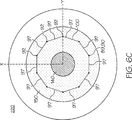
Der Begriff „Düsenöffnungsradius oder rNO”, wie er hier und in den beigefügten Patentansprüchen bezogen auf eine Düsenöffnung verwendet wird, bezieht sich auf den Radius, rSC, des kleinsten Kreises, SC, der die Düsenöffnung vollständig umgeben kann, d. h. rNO = rSC. Für Zwecke der Veranschaulichung vgl. die
Die Formwerkzeugbasis (
Die umgebende Wand (
Der Formwerkzeughohlraum (
Der Querschnitt des Formwerkzeughohlraums, Cx-Querschnitt, der auf die x-y-Ebene projiziert wird, kann jedwede regelmäßige oder unregelmäßige zweidimensionale Form sein. Vorzugsweise ist der Querschnitt des Formwerkzeughohlraums, Cx-Querschnitt, aus einem Polygon und einer Ellipse ausgewählt. Mehr bevorzugt ist der Querschnitt des Formwerkzeughohlraums, Cx-Querschnitt, im Wesentlichen ein kreisförmiger Querschnitt, der einen durchschnittlichen Radius, rC, aufweist (wobei der Radius rC vorzugsweise 20 bis 100 cm beträgt, wobei rC mehr bevorzugt 25 bis 65 cm beträgt, wobei rC insbesondere 40 bis 60 cm beträgt). Insbesondere ist der Formwerkzeughohlraum näherungsweise ein gerade zylindrisch geformter Bereich, der einen im Wesentlichen kreisförmigen Querschnitt, Cx-Querschnitt, aufweist, wobei der Formwerkzeughohlraum eine Symmetrieachse, Cx-Symmetrie, aufweist, die mit der Mittelachse des Formwerkzeughohlraums, CAchse, zusammenfällt, wobei der gerade zylindrisch geformte Bereich eine Querschnittsfläche, Cx-Fläche, aufweist, die wie folgt definiert ist:
Der Formwerkzeughohlraum (
Vorzugsweise ist der Kreisringloch-Bereich (
Vorzugsweise ist der Kreisring-Bereich (
Die Länge des Einbringzeitraums, CP, in Sekunden kann signifikant variieren. Beispielsweise wird die Länge des Einbringzeitraums, CP, von der Größe des Formwerkzeughohlraums, der durchschnittlichen Einbringgeschwindigkeit, CRDurchschnitt, und den Eigenschaften des aushärtbaren Gemischs (z. B. der Gelzeit) abhängen. Vorzugsweise beträgt der Einbringzeitraum, CP, 60 bis 900 Sekunden (mehr bevorzugt 60 bis 600 Sekunden, insbesondere 120 bis 360 Sekunden). Typischerweise wird der Einbringzeitraum, CP, durch die Gelzeit des aushärtbaren Gemischs beschränkt. Vorzugsweise wird der Einbringzeitraum, CP, weniger als oder gleich der Gelzeit des aushärtbaren Gemischs sein, das in den Formwerkzeughohlraum eingebracht wird. Mehr bevorzugt wird der Einbringzeitraum, CP, kürzer sein als die Gelzeit des aushärtbaren Gemischs.The length of the delivery period, CP, in seconds can vary significantly. For example, the length of the delivery period, CP, will depend on the size of the mold cavity, the average rate of introduction, CR average , and the properties of the curable composition (eg, gel time). Preferably, the introduction period, CP, is 60 to 900 seconds (more preferably 60 to 600 seconds, especially 120 to 360 seconds). Typically, the delivery period, CP, is limited by the gel time of the curable composition. Preferably, the introduction period, CP, will be less than or equal to the gel time of the curable composition being introduced into the mold cavity. More preferably, the loading period, CP, will be shorter than the gel time of the curable mixture.
Die Einbringgeschwindigkeit, CR, (in kg/s) kann im Verlauf des Einbringzeitraums, CP, variieren. Beispielsweise kann die Einbringgeschwindigkeit, CR, periodisch sein. D. h., die Einbringgeschwindigkeit, CR, kann vorübergehend an einem oder mehreren Zeitpunkt(en) im Verlauf des Einbringzeitraums auf Null fallen. Vorzugsweise wird das aushärtbare Gemisch in den Formwerkzeughohlraum bei einer in erster Linie konstanten Geschwindigkeit während des Einbringzeitraums eingebracht. Mehr bevorzugt wird das aushärtbare Gemisch in den Formwerkzeughohlraum bei einer in erster Linie konstanten Geschwindigkeit während des Einbringzeitraums, CP, mit einer durchschnittlichen Einbringgeschwindigkeit, CRDurchschnitt, von 0,015 bis 2 kg/s (mehr bevorzugt 0,015 bis 1 kg/s, insbesondere 0,08 bis 0,4 kg/s) eingebracht.The rate of introduction, CR, (in kg / s) may vary over the course of the delivery period, CP. For example, the delivery rate, CR, may be periodic. That is, the rate of introduction, CR, may be temporary at one or more times during the delivery period fall to zero. Preferably, the curable composition is introduced into the mold cavity at a primarily constant rate during the introduction period. More preferably, the curable mixture is injected into the mold cavity at a primarily constant rate during the introduction period, CP, at an average feed rate, CR average , of 0.015 to 2 kg / s (more preferably 0.015 to 1 kg / s, especially 0, 08 to 0.4 kg / s) introduced.
Der Einbringzeitraum, CP, ist in drei getrennte Phasen aufgeteilt, die als Anfangsphase, Übergangsphase und Restphase bezeichnet werden. Der Beginn der Anfangsphase entspricht dem Beginn des Einbringzeitraums, CP. Das Ende der Anfangsphase geht dem Beginn der Übergangsphase unmittelbar voraus. Das Ende der Übergangsphase geht dem Beginn der Restphase unmittelbar voraus. Das Ende der Restphase entspricht dem Ende des Einbringzeitraums, CP.The introduction period, CP, is divided into three separate phases, called the initial phase, the transition phase, and the remaining phase. The beginning of the initial phase corresponds to the beginning of the introduction period, CP. The end of the initial phase is immediately ahead of the beginning of the transition phase. The end of the transitional phase is immediately ahead of the beginning of the remaining phase. The end of the remaining phase corresponds to the end of the transfer period, CP.
Während des Einbringzeitraums, CP, bewegt sich die Düse oder wird überführt (führt z. B. eine teleskopartige Bewegung aus), so dass sich die Position der Düsenöffnung in alle drei Dimensionen bewegt. Während des Einbringzeitraums, CP, bewegt sich die Düse (
Während der Anfangsphase des Einbringzeitraums (d. h. für die Dauer der Anfangsphase) verbleibt die Position der Düsenöffnung innerhalb des Kreisringloch-Bereichs des Formwerkzeughohlraums. Die Position der Düsenöffnung kann während der Anfangsphase stationär bleiben, wobei sich der Anfangsphase-Startpunkt, SPIP, und der Anfangsphase-Endpunkt, EPIP, an der gleichen Position befinden (d. h. SPIP = EPIP). Vorzugsweise ist dann, wenn SPIP = EPIP, die Anfangsphase > 0 bis 90 Sekunden lang (mehr bevorzugt > 0 bis 60 Sekunden lang, insbesondere 5 bis 30 Sekunden lang). Insbesondere bleibt die Position der Düsenöffnung von dem Beginn der Anfangsphase des Einbringzeitraums bis zum Ansteigen der oberen Fläche des aushärtbaren Gemischs in dem Formwerkzeughohlraum, wobei in diesem Moment die Übergangsphase beginnt, stationär, wobei sich der Anfangsphase-Startpunkt, SPIP, (
Die Position der Düsenöffnung bewegt sich während der Übergangsphase des Einbringzeitraums von einem Punkt innerhalb des Kreisringloch-Bereichs des Formwerkzeughohlraums zu einem Punkt innerhalb des Kreisring-Bereichs. Vorzugsweise ist die Übergangsphase 0,02 bis 30 Sekunden lang (mehr bevorzugt 0,2 bis 5 Sekunden lang, insbesondere 0,6 bis 2 Sekunden lang). Vorzugsweise bewegt sich die Position der Düsenöffnung relativ zu der Mittelachse des Formwerkzeughohlraums, CAchse, während der Übergangsphase mit einer durchschnittlichen Geschwindigkeit von 10 bis 70 mm/s (mehr bevorzugt 15 bis 35 mm/s, insbesondere 20 bis 30 mm/s). Vorzugsweise stoppt die Bewegung der Position der Düsenöffnung während der Übergangsphase vorübergehend relativ zu der Mittelachse des Formwerkzeughohlraums, CAchse, (d. h. die Bewegung stoppt vorübergehend in der x-Dimension und der y-Dimension) an jedem Übergangsphase-Übergangspunkt, TPTP, (falls ein solcher vorliegt) und an dem Übergangsphase-Endpunkt, EPTP. Vorzugsweise bewegt sich die Position der Düsenöffnung während der Übergangsphase mit einer konstanten Geschwindigkeit relativ zu der Mittelachse des Formwerkzeughohlraums, CAchse, (d. h. die Bewegung stoppt vorübergehend in der x-Dimension und der y-Dimension) von dem Übergangsphase-Startpunkt, SPTP, durch jedwede Übergangsphase-Übergangspunkte, TPTP, zu dem Übergangsphase-Endpunkt, EPTP. Vorzugsweise bewegt sich die Position der Düsenöffnung während der Übergangsphase von dem Übergangsphase-Startpunkt, SPTP, durch eine Mehrzahl von Übergangsphase-Übergangspunkten, TPTP, zu dem Übergangsphase-Endpunkt, EPTP, wobei der Übergangsphase-Weg, der auf die x-y-Ebene projiziert wird, näherungsweise einer Kurve entspricht (wobei mehr bevorzugt der Übergangsphase-Weg einer Spiralform entspricht). Insbesondere bewegt sich die Position der Düsenöffnung während der Übergangsphase von dem Übergangsphase-Startpunkt, SPTP, direkt zu dem Übergangsphase-Endpunkt, EPTP, wobei der Übergangsphase-Weg, der auf die x-y-Ebene projiziert wird, eine Gerade ist. The position of the nozzle orifice moves during the transient phase of the delivery period from a point within the annulus area of the die cavity to a point within the annulus region. Preferably, the transition phase is 0.02 to 30 seconds (more preferably 0.2 to 5 seconds, especially 0.6 to 2 seconds). Preferably, the position of the nozzle opening relative to the center axis of the mold cavity, C axis , moves during the transitional phase at an average speed of 10 to 70 mm / s (more preferably 15 to 35 mm / s, especially 20 to 30 mm / s). Preferably, the movement of the position of the nozzle orifice during the transient phase temporarily stops relative to the center axis of the mold cavity, C axis (ie, the transiently stops in the x-dimension and the y-dimension) at each transient phase transition point, TP TP one is present) and at the transition phase endpoint, EP TP . Preferably, the position of the nozzle orifice during the transition phase moves at a constant velocity relative to the center axis of the mold cavity, C axis , (ie, the motion temporarily stops in the x-dimension and the y-dimension) from the transition phase starting point, SP TP . through any transition phase transition points, TP TP , to the transition phase endpoint, EP TP . Preferably, the position of the nozzle orifice during the transition phase moves from the transition phase starting point, SP TP , through a plurality of transition phase transition points, TP TP , to the transition phase end point, EP TP , wherein the transition phase path, which points to the xy- Plane approximates a curve (more preferably the transition phase path corresponds to a spiral shape). In particular, during the transition phase, the position of the nozzle orifice moves from the transition phase start point, SP TP , directly to the transition phase end point, EP TP , where the transition phase path, which is projected onto the xy plane, is a straight line.
Die
Die Position der Düsenöffnung bleibt während der Restphase des Einbringzeitraums innerhalb des Kreisring-Bereichs (d. h. die Position der Düsenöffnung kann für einen Teil der Restphase des Einbringzeitraums den Kreisringloch-Bereich durchlaufen oder in diesem verbleiben). Vorzugsweise bleibt die Position der Düsenöffnung während der Restphase des Einbringzeitraums innerhalb des Kreisring-Bereichs (d. h. für die Dauer der Restphase). Vorzugsweise ist die Restphase ≥ 10 Sekunden lang. Mehr bevorzugt ist die Restphase
Die
Das aushärtbare Gemisch umfasst vorzugsweise ein flüssiges Vorpolymermaterial und eine Mehrzahl von Mikroelementen, wobei die Mehrzahl von Mikroelementen in dem flüssigen Vorpolymermaterial einheitlich dispergiert ist.The curable composition preferably comprises a liquid prepolymer material and a plurality of microelements, the plurality of microelements being uniformly dispersed in the liquid prepolymer material.
Das flüssige Vorpolymermaterial polymerisiert (d. h., härtet aus) vorzugsweise derart, dass ein Material gebildet wird, das aus Poly(urethan), Polysulfon, Polyethersulfon, Nylon, Polyether, Polyester, Polystyrol, Acrylpolymer, Polyharnstoff, Polyamid, Polyvinylchlorid, Polyvinylfluorid, Polyethylen, Polypropylen, Polybutadien, Polyethylenimin, Polyacrylnitril, Polyethylenoxid, Polyolefin, Poly(alkyl)acrylat, Poly(alkyl)methacrylat, Polyamid, Polyetherimid, Polyketon, Epoxy, Silikon, einem Polymer, das aus Ethylen-Propylen-Dien-Monomer ausgebildet ist, Protein, Polysaccharid, Polyacetat und einer Kombination von mindestens zwei der vorstehend genannten Materialien ausgewählt ist. Vorzugsweise polymerisiert das flüssige Vorpolymermaterial derart, dass ein Material gebildet wird, das ein Polyurethan) umfasst. Mehr bevorzugt polymerisiert das flüssige Vorpolymermaterial derart, dass ein Material gebildet wird, das ein Polyurethan umfasst. Insbesondere polymerisiert (härtet aus) das flüssige Vorpolymermaterial derart, dass ein Polyurethan gebildet wird.The liquid prepolymer material preferably polymerizes (ie, cures) to form a material comprised of poly (urethane), polysulfone, polyethersulfone, nylon, polyether, polyester, polystyrene, acrylic polymer, polyurea, polyamide, polyvinyl chloride, polyvinyl fluoride, polyethylene, Polypropylene, polybutadiene, polyethylenimine, polyacrylonitrile, polyethylene oxide, polyolefin, poly (alkyl) acrylate, poly (alkyl) methacrylate, polyamide, polyetherimide, polyketone, epoxy, silicone, a polymer formed from ethylene-propylene-diene monomer, protein , Polysaccharide, polyacetate and a combination of at least two of the aforementioned materials. Preferably, the liquid prepolymer material polymerizes such that a material comprising a polyurethane is formed. More preferably, the liquid prepolymer material polymerizes such that a material comprising a polyurethane is formed. In particular, the liquid prepolymer material polymerizes (cures) such that a polyurethane is formed.
Vorzugsweise umfasst das flüssige Vorpolymermaterial ein Polyisocyanat-enthaltendes Material. Mehr bevorzugt umfasst das flüssige Vorpolymermaterial das Reaktionsprodukt eines Polyisocyanats (z. B. Diisocyanat) und eines Hydroxyl-enthaltenden Materials.Preferably, the liquid prepolymer material comprises a polyisocyanate-containing material. More preferably, the liquid prepolymer material comprises the reaction product of a polyisocyanate (eg, diisocyanate) and a hydroxyl-containing material.
Vorzugsweise ist das Polyisocyanat aus Methylen-bis-4,4'-cyclohexylisocyanat, Cyclohexyldiisocyanat, Isophorondiisocyanat, Hexamethylendiisocyanat, Propylen-1,2-diisocyanat, Tetramethylen-1,4-diisocyanat, 1,6-Hexamethylendiisocyanat, Dodecan-1,12-diisocyanat, Cyclobutan-1,3-diisocyanat, Cyclohexan-1,3-diisocyanat, Cyclohexan-1,4-diisocyanat, 1-Isocyanato-3,3,5-trimethyl-5-isocyanatomethylcyclohexan, Methylcyclohexylendiisocyanat, einem Triisocyanat von Hexamethylendiisocyanat, einem Triisocyanat von 2,4,4-Trimethyl-1,6-hexandiisocyanat, einem Uretdion von Hexamethylendiisocyanat, Ethylendiisocyanat, 2,2,4-Trimethylhexamethylendiisocyanat, 2,4,4-Trimethylhexamethylendiisocyanat, Dicyclohexylmethandiisocyanat und Kombinationen davon ausgewählt. Insbesondere ist das Polyisocyanat aliphatisch und weist weniger als 14 Prozent nicht umgesetzte Isocyanatgruppen auf. Preferably, the polyisocyanate is selected from methylene-bis-4,4'-cyclohexyl isocyanate, cyclohexyl diisocyanate, isophorone diisocyanate, hexamethylene diisocyanate, propylene-1,2-diisocyanate, tetramethylene-1,4-diisocyanate, 1,6-hexamethylene diisocyanate, dodecane-1,12- diisocyanate, cyclobutane-1,3-diisocyanate, cyclohexane-1,3-diisocyanate, cyclohexane-1,4-diisocyanate, 1-isocyanato-3,3,5-trimethyl-5-isocyanatomethylcyclohexane, methylcyclohexylene diisocyanate, a triisocyanate of hexamethylene diisocyanate, a Triisocyanate of 2,4,4-trimethyl-1,6-hexane diisocyanate, a uretdione of hexamethylene diisocyanate, ethylene diisocyanate, 2,2,4-trimethylhexamethylene diisocyanate, 2,4,4-trimethylhexamethylene diisocyanate, dicyclohexylmethane diisocyanate, and combinations thereof. In particular, the polyisocyanate is aliphatic and has less than 14 percent unreacted isocyanate groups.
Vorzugsweise ist das mit der vorliegenden Erfindung verwendete Hydroxyl-enthaltende Material ein Polyol. Beispiele für Polyole umfassen Polyetherpolyole, Polybutadien mit endständigen Hydroxygruppen (einschließlich teilweise und vollständig hydrierte Derivate), Polyesterpolyole, Polycaprolactonpolyole, Polycarbonatpolyole und Gemische davon.Preferably, the hydroxyl-containing material used with the present invention is a polyol. Examples of polyols include polyether polyols, hydroxy-terminated polybutadiene (including partially and fully hydrogenated derivatives), polyester polyols, polycaprolactone polyols, polycarbonate polyols, and mixtures thereof.
Bevorzugte Polyole umfassen Polyetherpolyole. Beispiele für Polyetherpolyole umfassen Polytetramethylenetherglykol („PTMEG”), Polyethylenpropylenglykol, Polyoxypropylenglykol und Gemische davon. Die Kohlenwasserstoffkette kann gesättigte oder ungesättigte Bindungen und substituierte oder unsubstituierte aromatische und cyclische Gruppen aufweisen. Vorzugsweise umfasst das Polyol der vorliegenden Erfindung PTMEG. Geeignete Polyesterpolyole umfassen, ohne darauf beschränkt zu sein, Polyethylenadipatglykol, Polybutylenadipatglykol, Polyethylenpropylenadipatglykol, o-Phthalat-1,6-hexandiol, Poly(hexamethylenadipat)glykol und Gemische davon. Die Kohlenwasserstoffkette kann gesättigte oder ungesättigte Bindungen oder substituierte oder unsubstituierte aromatische und cyclische Gruppen aufweisen. Geeignete Polycaprolactonpolyole umfassen, ohne darauf beschränkt zu sein, 1,6-Hexandiol-initiiertes Polycaprolacton, Diethylenglykol-initiiertes Polycaprolacton, Trimethylolpropan-initiiertes Polycaprolacton, Neopentylglykol-initiiertes Polycaprolacton, 1,4-Butandiol-initiiertes Polycaprolacton, PTMEG-initiiertes Polycaprolacton und Gemische davon. Die Kohlenwasserstoffkette kann gesättigte oder ungesättigte Bindungen oder substituierte oder unsubstituierte aromatische und cyclische Gruppen aufweisen. Geeignete Polycarbonate umfassen unter anderem Polyphthalatcarbonat und Poly(hexamethylencarbonat)glykol.Preferred polyols include polyether polyols. Examples of polyether polyols include polytetramethylene ether glycol ("PTMEG"), polyethylene propylene glycol, polyoxypropylene glycol, and mixtures thereof. The hydrocarbon chain may have saturated or unsaturated bonds and substituted or unsubstituted aromatic and cyclic groups. Preferably, the polyol of the present invention comprises PTMEG. Suitable polyester polyols include, but are not limited to, polyethylene adipate glycol, polybutylene adipate glycol, polyethylene propylene adipate glycol, o-phthalate-1,6-hexanediol, poly (hexamethylene adipate) glycol, and mixtures thereof. The hydrocarbon chain may have saturated or unsaturated bonds or substituted or unsubstituted aromatic and cyclic groups. Suitable polycaprolactone polyols include, but are not limited to, 1,6-hexanediol-initiated polycaprolactone, diethylene glycol-initiated polycaprolactone, trimethylolpropane-initiated polycaprolactone, neopentyl glycol-initiated polycaprolactone, 1,4-butanediol-initiated polycaprolactone, PTMEG-initiated polycaprolactone, and mixtures thereof , The hydrocarbon chain may have saturated or unsaturated bonds or substituted or unsubstituted aromatic and cyclic groups. Suitable polycarbonates include, but are not limited to, polyphthalate carbonate and poly (hexamethylene carbonate) glycol.
Vorzugsweise ist die Mehrzahl von Mikroelementen aus eingeschlossenen Gasblasen, polymeren Materialien mit hohlem Kern (d. h. Mikrokügelchen), flüssigkeitsgefüllten polymeren Materialien mit hohlem Kern, wasserlöslichen Materialien (z. B. Cyclodextrin) und einem Material mit unlöslicher Phase (z. B. Mineralöl) ausgewählt. Vorzugsweise handelt es sich bei der Mehrzahl von Mikroelementen um Mikrokügelchen, wie z. B. Polyvinylalkohole, Pektin, Polyvinylpyrrolidon, Hydroxyethylcellulose, Methylcellulose, Hydropropylmethylcellulose, Carboxymethylcellulose, Hydroxypropylcellulose, Polyacrylsäuren, Polyacrylamide, Polyethylenglykole, Polyhydroxyetheracrylite, Stärken, Maleinsäurecopolymere, Polyethylenoxid, Polyurethane, Cyclodextrin und Kombinationen davon (z. B. ExpancelTM von Akzo Nobel, Sundsvall, Schweden). Die Mikrokügelchen können chemisch modifiziert werden, um ihre Löslichkeitseigenschaften, Quelleigenschaften und andere Eigenschaften z. B. durch Verzweigen, Blockieren und Vernetzen zu verändern. Vorzugsweise weisen die Mikrokügelchen einen mittleren Durchmesser von weniger als 150 μm und mehr bevorzugt einen mittleren Durchmesser von weniger als 50 μm auf. Insbesondere weisen die Mikrokügelchen 48 einen mittleren Durchmesser auf, der weniger als 15 μm beträgt. Es sollte beachtet werden, dass der mittlere Durchmesser der Mikrokügelchen variiert werden kann und verschiedene Größen oder Gemische verschiedener Mikrokügelchen 48 verwendet werden können. Ein am meisten bevorzugtes Material für die Mikrokügelchen ist ein Copolymer aus Acrylnitril und Vinylidenchlorid (z. B. Expancel®, das von Akzo Nobel erhältlich ist).Preferably, the plurality of microelements are selected from occluded gas bubbles, hollow core polymeric materials (ie, microspheres), liquid filled hollow core polymeric materials, water soluble materials (eg, cyclodextrin), and an insoluble phase material (eg, mineral oil) , Preferably, the plurality of microelements are microspheres, such as e.g. Polyvinyl alcohols, pectin, polyvinylpyrrolidone, hydroxyethylcellulose, methylcellulose, hydropropylmethylcellulose, carboxymethylcellulose, hydroxypropylcellulose, polyacrylic acids, polyacrylamides, polyethylene glycols, polyhydroxyetheracrylates, starches, maleic acid copolymers, polyethylene oxide, polyurethanes, cyclodextrin and combinations thereof (e.g., Expancel ™ from Akzo Nobel, Sundsvall , Sweden). The microspheres can be chemically modified to improve their solubility properties, swelling properties and other properties, e.g. B. by branching, blocking and networking to change. Preferably, the microspheres have an average diameter of less than 150 microns, and more preferably an average diameter of less than 50 microns. In particular, the microspheres 48 have an average diameter which is less than 15 μm. It should be noted that the average diameter of the microspheres can be varied and different sizes or mixtures of different microspheres 48 used. A most preferred material for the microspheres is a copolymer of acrylonitrile and vinylidene chloride (z. B. Expancel ®, which is available from Akzo Nobel).
Das flüssige Vorpolymermaterial umfasst ferner gegebenenfalls ein Härtungsmittel. Bevorzugte Härtungsmittel umfassen Diamine. Geeignete Polydiamine umfassen sowohl primäre als auch sekundäre Amine. Bevorzugte Polydiamine umfassen, ohne darauf beschränkt zu sein, Diethyltoluoldiamin („DETDA”), 3,5-Dimethylthio-2,4-toluoldiamin und Isomere davon, 3,5-Diethyltoluol-2,4-diamin und Isomere davon (z. B. 3,5-Diethyltoluol-2,6-diamin), 4,4'-Bis(sec-butylamino)-diphenylmethan, 1,4-Bis-(sec-butylamino)-benzol, 4,4'-Methylen-bis(2-chloranilin), 4,4'-Methylen-bis-(3-chlor-2,6-diethylanilin) („MCDEA”), Polytetramethylenoxiddi-p-aminobenzoat, N,N'-Dialkyldiaminodiphenylmethan, p,p'-Methylendianilin („MDA”), m-Phenylendiamin („MPDA”), Methylen-bis-2-chloranilin („MBOCA”), 4,4'-Methylen-bis-(2-chloranilin) („MOCA”), 4,4'-Methylen-bis-(2,6-diethylanilin) („MDEA”), 4,4'-Methylen-bis-(2,3-dichloranilin) („MDCA”), 4,4'-Diamino-3,3'-diethyl-5,5'-dimethyldiphenylmethan, 2,2',3,3'-Tetrachlordiaminodiphenylmethan, Trimethylenglykoldi-p-aminobenzoat und Gemische davon. Vorzugsweise ist das Diamin-Härtungsmittel aus 3,5-Dimethylthio-2,4-toluoldiamin und Isomeren davon ausgewählt.The liquid prepolymer material optionally further comprises a curing agent. Preferred curing agents include diamines. Suitable polydiamines include both primary and secondary amines. Preferred polydiamines include, but are not limited to, diethyltoluenediamine ("DETDA"), 3,5-dimethylthio-2,4-toluenediamine and isomers thereof, 3,5-diethyltoluene-2,4-diamine and isomers thereof (e.g. 3,5-diethyltoluene-2,6-diamine), 4,4'-bis (sec-butylamino) -diphenylmethane, 1,4-bis (sec-butylamino) -benzene, 4,4'-methylene-bis (2-chloroaniline), 4,4'-methylenebis (3-chloro-2,6-diethylaniline) ("MCDEA"), polytetramethylene oxide di-p-aminobenzoate, N, N'-dialkyldiaminodiphenylmethane, p, p'- Methylenedianiline ("MDA"), m-phenylenediamine ("MPDA"), methylene-bis-2-chloroaniline ("MBOCA"), 4,4'-methylenebis (2-chloroaniline) ("MOCA"), 4 , 4'-methylenebis (2,6-diethylaniline) ("MDEA"), 4,4'-methylenebis (2,3-dichloroaniline) ("MDCA"), 4,4'-diamino- 3,3'-diethyl-5,5'-dimethyldiphenylmethane, 2,2 ', 3,3'-tetrachlorodiaminodiphenylmethane, trimethylene glycol di-p-aminobenzoate, and mixtures thereof. Preferably, the diamine curing agent is selected from 3,5-dimethylthio-2,4-toluenediamine and isomers thereof.
Härtungsmittel können auch Diole, Triole, Tetraole und Härtungsmittel mit endständigen Hydroxygruppen umfassen. Geeignete Diole, Triole und Tetraolgruppen umfassen Ethylenglykol, Diethylenglykol, Polyethylenglykol, Propylenglykol, Polypropylenglykol, Polytetramethylenetherglykol mit niedrigem Molekulargewicht, 1,3-Bis(2-hydroxyethoxy)benzol, 1,3-Bis-[2-(2-hydroxyethoxy)ethoxy]benzol, 1,3-Bis-{2-[2-(2-hydroxyethoxy)ethoxy]ethoxy}benzol, 1,4-Butandiol, 1,5-Pentandiol, 1,6-Hexandiol, Resorcin-di-(beta-hydroxyethyl)ether, Hydrochinon-di-(beta-hydroxyethyl)ether und Gemische davon. Bevorzugte Härtungsmittel mit endständigen Hydroxygruppen umfassen 1,3-Bis(2-hydroxyethoxy)benzol, 1,3-Bis-[2-(2-hydroxyethoxy)ethoxy]benzol, 1,3-Bis-{2-[2-(2-hydroxyethoxy)ethoxy]ethoxy}benzol, 1,4-Butandiol und Gemische davon. Die Härtungsmittel mit endständigen Hydroxygruppen und die Diamin-Härtungsmittel können eine oder mehrere gesättigte, ungesättigte, aromatische und cyclische Gruppe(n) aufweisen. Zusätzlich können die Härtungsmittel mit endständigen Hydroxygruppen und die Diamin-Härtungsmittel eine oder mehrere Halogengruppe(n) aufweisen.Curing agents may also include diols, triols, tetraols and curing agents include terminal hydroxy groups. Suitable diols, triols and tetraol groups include ethylene glycol, diethylene glycol, polyethylene glycol, propylene glycol, polypropylene glycol, low molecular weight polytetramethylene ether glycol, 1,3-bis (2-hydroxyethoxy) benzene, 1,3-bis [2- (2-hydroxyethoxy) ethoxy] benzene, 1,3-bis (2- [2- (2-hydroxyethoxy) ethoxy] ethoxy} benzene, 1,4-butanediol, 1,5-pentanediol, 1,6-hexanediol, resorcinol di (beta) hydroxyethyl) ether, hydroquinone di (beta-hydroxyethyl) ether and mixtures thereof. Preferred hydroxy terminated curing agents include 1,3-bis (2-hydroxyethoxy) benzene, 1,3-bis [2- (2-hydroxyethoxy) ethoxy] benzene, 1,3-bis- {2- [2- (2 -hydroxyethoxy) ethoxy] ethoxy} benzene, 1,4-butanediol and mixtures thereof. The hydroxy-terminated curing agents and the diamine curing agents may have one or more saturated, unsaturated, aromatic and cyclic groups. In addition, the hydroxy-terminated curing agents and the diamine curing agents may have one or more halo groups.
Vorzugsweise wird der Körper geschält oder in sonstiger Weise in eine Mehrzahl von Polierschichten mit einer gewünschten Dicke aufgeteilt.Preferably, the body is peeled or otherwise split into a plurality of polishing layers having a desired thickness.
Vorzugsweise umfasst das Verfahren der vorliegenden Erfindung zur Bildung einer Polierschicht für ein chemisch-mechanisches Polierkissen ferner: Bereitstellen eines Fensterblocks und Anordnen des Fensterblocks in dem Formwerkzeughohlraum. Der Fensterblock kann in dem Formwerkzeughohlraum vor oder nach dem Überführen des aushärtbaren Gemischs in den Formwerkzeughohlraum angeordnet werden. Vorzugsweise wird der Fensterblock in dem Formwerkzeughohlraum angeordnet, bevor das aushärtbare Gemisch in den Formwerkzeughohlraum überführt wird. Vorzugsweise umfasst das Verfahren der vorliegenden Erfindung ferner: Befestigen des Fensterblocks an der Formwerkzeugbasis (vorzugsweise an der horizontalen inneren Grenze der Formwerkzeugbasis). Vorzugsweise umfasst das Verfahren der vorliegenden Erfindung ferner: Bereitstellen eines Fensterblock-Haftmittels und Befestigen des Fensterblocks an der Formwerkzeugbasis (vorzugsweise an der horizontalen inneren Grenze der Formwerkzeugbasis). Es wird davon ausgegangen, dass das Befestigen des Fensterblocks an der Formwerkzeugbasis die Bildung von Verformungen des Fensters (z. B. ein Ausbauchen des Fensters auswärts von der Polierschicht) vermindert, wenn ein Körper in eine Mehrzahl von Polierschichten aufgeteilt (z. B. geschält) wird.Preferably, the method of the present invention for forming a polishing layer for a chemical mechanical polishing pad further comprises providing a window block and placing the window block in the mold cavity. The window block may be placed in the mold cavity prior to or after transfer of the curable composition into the mold cavity. Preferably, the window block is placed in the mold cavity before the curable composition is transferred to the mold cavity. Preferably, the method of the present invention further comprises: attaching the window block to the mold base (preferably at the horizontal inner boundary of the mold base). Preferably, the method of the present invention further comprises providing window block adhesive and securing the window block to the mold base (preferably at the horizontal inner edge of the mold base). It is believed that securing the window block to the mold base reduces the formation of deformations of the window (eg, bulging the window outwardly from the polishing layer) when a body is split (eg, peeled) into a plurality of polishing layers ) becomes.
Fensterblockformulierungen, die zur Verwendung in chemisch-mechanischen Polierkissen geeignet sind, sind bekannt.Window block formulations suitable for use in chemical mechanical polishing pads are known.
Vorzugsweise enthalten Körper, die mit dem Verfahren der vorliegenden Erfindung hergestellt worden sind, verglichen mit Körpern, die mit dem gleichen Verfahren hergestellt worden ist, jedoch mit der Ausnahme, dass sich während des Einbringzeitraums, CP, die Position der Düsenöffnung nur in einer Dimension entlang der Mittelachse des Formwerkzeughohlraums, CAchse, bewegt (d. h. zum Aufrechterhalten der Position der Düsenöffnung bei einem eingestellten Höhenniveau oberhalb der oberen Fläche des aushärtbaren Materials, während es sich in dem Formwerkzeughohlraum ansammelt), weniger Dichtedefekte. Mehr bevorzugt stellen Körper, die mit dem Verfahren der vorliegenden Erfindung hergestellt worden sind, mindestens 50% mehr (mehr bevorzugt mindestens 75% mehr, insbesondere mindestens 100% mehr) Polierschichten, die frei von Dichtedefekten sind, pro Körper bereit. Noch mehr bevorzugt weist der Formwerkzeughohlraum einen im Wesentlichen kreisförmigen Querschnitt mit einem durchschnittlichen Radius rC auf, wobei rC 40 bis 60 cm ist und wobei der mit dem Verfahren der vorliegenden Erfindung erzeugte Körper eine 2-fache Zunahme (mehr bevorzugt eine 3-fache Zunahme) der Anzahl von Polierschichten bereitstellt, die frei von Dichtedefekten sind, verglichen mit der Anzahl von Polierschichten, die frei von Dichtedefekten sind, die durch einen Körper bereitgestellt werden, der mit dem gleichen Verfahren hergestellt worden ist, jedoch mit der Ausnahme, dass sich während des Einbringzeitraums, CP, die Position der Düsenöffnung nur in einer Dimension entlang der Mittelachse des Formwerkzeughohlraums, CAchse, bewegt.Preferably, bodies made by the process of the present invention contain as compared to bodies made by the same process except that during the introduction period, CP, the position of the nozzle orifice is along only one dimension the central axis of the mold cavity, C axis , moves (ie, to maintain the position of the nozzle orifice at a set height level above the upper surface of the curable material as it accumulates in the mold cavity) less density defects. More preferably, bodies made by the method of the present invention provide at least 50% more (more preferably, at least 75% more, more preferably at least 100% more) polishing layers free of density defects per body. Even more preferably, the mold cavity has a substantially circular cross-section with an average radius r C where
ZITATE ENTHALTEN IN DER BESCHREIBUNG QUOTES INCLUDE IN THE DESCRIPTION
Diese Liste der vom Anmelder aufgeführten Dokumente wurde automatisiert erzeugt und ist ausschließlich zur besseren Information des Lesers aufgenommen. Die Liste ist nicht Bestandteil der deutschen Patent- bzw. Gebrauchsmusteranmeldung. Das DPMA übernimmt keinerlei Haftung für etwaige Fehler oder Auslassungen.This list of the documents listed by the applicant has been generated automatically and is included solely for the better information of the reader. The list is not part of the German patent or utility model application. The DPMA assumes no liability for any errors or omissions.
Zitierte PatentliteraturCited patent literature
- US 5578362 [0005] US 5578362 [0005]
Zitierte Nicht-PatentliteraturCited non-patent literature
- ASTM D3795-00a [0039] ASTM D3795-00a [0039]
Claims (10)
Applications Claiming Priority (2)
| Application Number | Priority Date | Filing Date | Title |
|---|---|---|---|
| US13/210,432 | 2011-08-16 | ||
| US13/210,432 US8444727B2 (en) | 2011-08-16 | 2011-08-16 | Method of manufacturing chemical mechanical polishing layers |
Publications (1)
| Publication Number | Publication Date |
|---|---|
| DE102012015942A1 true DE102012015942A1 (en) | 2013-02-21 |
Family
ID=47625351
Family Applications (1)
| Application Number | Title | Priority Date | Filing Date |
|---|---|---|---|
| DE102012015942A Withdrawn DE102012015942A1 (en) | 2011-08-16 | 2012-08-10 | Process for the preparation of chemical-mechanical polishing layers |
Country Status (7)
| Country | Link |
|---|---|
| US (1) | US8444727B2 (en) |
| JP (1) | JP5900227B2 (en) |
| KR (1) | KR101950040B1 (en) |
| CN (1) | CN102950550B (en) |
| DE (1) | DE102012015942A1 (en) |
| FR (1) | FR2979070B1 (en) |
| TW (1) | TWI593510B (en) |
Families Citing this family (7)
| Publication number | Priority date | Publication date | Assignee | Title |
|---|---|---|---|---|
| US8709114B2 (en) * | 2012-03-22 | 2014-04-29 | Rohm And Haas Electronic Materials Cmp Holdings, Inc. | Method of manufacturing chemical mechanical polishing layers |
| US9034063B2 (en) * | 2012-09-27 | 2015-05-19 | Rohm And Haas Electronic Materials Cmp Holdings, Inc. | Method of manufacturing grooved chemical mechanical polishing layers |
| US20150306731A1 (en) * | 2014-04-25 | 2015-10-29 | Rohm And Haas Electronic Materials Cmp Holdings, Inc. | Chemical mechanical polishing pad |
| US10722999B2 (en) * | 2016-06-17 | 2020-07-28 | Rohm And Haas Electronic Materials Cmp Holdings, Inc. | High removal rate chemical mechanical polishing pads and methods of making |
| KR101857435B1 (en) * | 2016-12-15 | 2018-05-15 | 한국생산기술연구원 | Surface plate having porous structure and method for manufacturing the same |
| CN108215028B (en) * | 2017-12-15 | 2019-12-31 | 湖北鼎龙控股股份有限公司 | Mold system for preparing polishing pad and use method thereof |
| CN110270940B (en) * | 2019-07-25 | 2020-09-25 | 湖北鼎汇微电子材料有限公司 | Continuous casting manufacturing method of polishing pad |
Citations (1)
| Publication number | Priority date | Publication date | Assignee | Title |
|---|---|---|---|---|
| US5578362A (en) | 1992-08-19 | 1996-11-26 | Rodel, Inc. | Polymeric polishing pad containing hollow polymeric microelements |
Family Cites Families (16)
| Publication number | Priority date | Publication date | Assignee | Title |
|---|---|---|---|---|
| DE1916330A1 (en) | 1969-03-29 | 1970-10-08 | Richard Zippel & Co Kg Farbspr | Plant for the production of large or complex shaped molded parts from liquid multi-component plastics |
| DE2127582C3 (en) * | 1971-06-03 | 1975-06-12 | Krauss-Maffei Ag, 8000 Muenchen | Method for producing a cell-shaped article from polymer! plastic |
| US4158535A (en) | 1977-01-25 | 1979-06-19 | Olin Corporation | Generation of polyurethane foam |
| US4687531A (en) * | 1982-01-26 | 1987-08-18 | Potoczky Joseph B | Method for centrifugal spray molding of thin-walled structures |
| CA2197136A1 (en) * | 1997-02-10 | 1998-08-10 | Dave Cockle | Plastic molding process and products produced thereby |
| ID24359A (en) * | 1997-05-16 | 2000-07-13 | Unilever Nv | PROCESS FOR PRODUCING A DETERGENT COMPOSITION |
| EP1268134A1 (en) * | 1999-12-14 | 2003-01-02 | Rodel Holdings, Inc. | Method of manufacturing a polymer or polymer composite polishing pad |
| GB0008553D0 (en) * | 2000-04-06 | 2000-05-24 | Unilever Plc | Process and apparatus for the production of a detergent bar |
| JP4614406B2 (en) * | 2000-12-27 | 2011-01-19 | 東洋ゴム工業株式会社 | Method for producing polyurethane foam for semiconductor polishing |
| US20060108701A1 (en) * | 2004-11-23 | 2006-05-25 | Saikin Allan H | Method for forming a striation reduced chemical mechanical polishing pad |
| TWI385050B (en) * | 2005-02-18 | 2013-02-11 | Nexplanar Corp | Customized polishing pads for cmp and methods of fabrication and use thereof |
| CN101134303A (en) * | 2006-08-30 | 2008-03-05 | 力晶半导体股份有限公司 | Polishing pad and method of producing the same |
| US8118644B2 (en) * | 2008-10-16 | 2012-02-21 | Rohm And Haas Electronic Materials Cmp Holdings, Inc. | Chemical mechanical polishing pad having integral identification feature |
| US8083570B2 (en) * | 2008-10-17 | 2011-12-27 | Rohm And Haas Electronic Materials Cmp Holdings, Inc. | Chemical mechanical polishing pad having sealed window |
| US7947098B2 (en) * | 2009-04-27 | 2011-05-24 | Rohm And Haas Electronic Materials Cmp Holdings, Inc. | Method for manufacturing chemical mechanical polishing pad polishing layers having reduced gas inclusion defects |
| US8552980B2 (en) | 2009-04-30 | 2013-10-08 | Gregory A. Shaver | Computer input devices and associated computing devices, software, and methods |
-
2011
- 2011-08-16 US US13/210,432 patent/US8444727B2/en active Active
-
2012
- 2012-08-03 JP JP2012173342A patent/JP5900227B2/en active Active
- 2012-08-07 TW TW101128395A patent/TWI593510B/en active
- 2012-08-10 DE DE102012015942A patent/DE102012015942A1/en not_active Withdrawn
- 2012-08-15 CN CN201210290726.4A patent/CN102950550B/en active Active
- 2012-08-16 KR KR1020120089274A patent/KR101950040B1/en active IP Right Grant
- 2012-08-16 FR FR1257818A patent/FR2979070B1/en active Active
Patent Citations (1)
| Publication number | Priority date | Publication date | Assignee | Title |
|---|---|---|---|---|
| US5578362A (en) | 1992-08-19 | 1996-11-26 | Rodel, Inc. | Polymeric polishing pad containing hollow polymeric microelements |
Non-Patent Citations (1)
| Title |
|---|
| ASTM D3795-00a |
Also Published As
| Publication number | Publication date |
|---|---|
| FR2979070B1 (en) | 2016-02-05 |
| CN102950550B (en) | 2015-10-28 |
| KR101950040B1 (en) | 2019-02-19 |
| FR2979070A1 (en) | 2013-02-22 |
| TWI593510B (en) | 2017-08-01 |
| US20130042536A1 (en) | 2013-02-21 |
| JP2013039663A (en) | 2013-02-28 |
| JP5900227B2 (en) | 2016-04-06 |
| CN102950550A (en) | 2013-03-06 |
| KR20130020588A (en) | 2013-02-27 |
| TW201318769A (en) | 2013-05-16 |
| US8444727B2 (en) | 2013-05-21 |
Similar Documents
| Publication | Publication Date | Title |
|---|---|---|
| DE102013004947A1 (en) | Process for the preparation of chemical-mechanical polishing layers | |
| DE102013004942A1 (en) | Process for the preparation of chemical mechanical polishing layers having a window | |
| DE102012015942A1 (en) | Process for the preparation of chemical-mechanical polishing layers | |
| DE102006015768B4 (en) | A method of forming a porous reaction-injection molded chemical mechanical polishing pad | |
| DE60109601T2 (en) | RILLEN POLISHING PILLOWS FOR CHEMICAL-MECHANICAL PLANARIZATION | |
| DE102015003240A1 (en) | CHEMICAL-MECHANICAL POLISHING CUSHION WITH POLISHING LAYER AND WINDOW | |
| DE102014015664A1 (en) | Process for the chemical mechanical polishing of silicon wafers | |
| DE69827147T2 (en) | METHOD FOR PRODUCING A POLISHING PILLOW | |
| DE102013018258A1 (en) | Soft and conditionable chemical-mechanical polishing pad | |
| DE60308946T2 (en) | Polishing pad and method of making a polishing pad | |
| DE102014012378A1 (en) | PROCESS FOR CHEMICAL-MECHANICAL POLISHING OF A SUBSTRATE | |
| DE102014007027A1 (en) | Soft and conditionable chemical-mechanical window polishing pad | |
| DE102015006980A1 (en) | Chemical-mechanical polishing process | |
| DE102010018012B4 (en) | Method of making polishing layers of a chemical mechanical polishing pad with reduced gas inclusion defects | |
| DE102014007002A1 (en) | Chemical-mechanical multilayer polishing pad stack with soft and conditionable polishing layer | |
| DE102015003200A1 (en) | SOFT AND CONDENSABLE CHEMICAL MECHANICAL POLISHING CUSHION WITH WINDOW | |
| DE102014012353A1 (en) | CHEMICAL MECHANICAL POLISH PILLOW | |
| DE102016007767A1 (en) | FORMULATION FOR A COMPOSITE COATING LAYER FOR A CHEMICAL-MECHANICAL POLISHING PILLOW | |
| DE102014007024A1 (en) | Soft and conditionable chemo-mechanical polishing pad stack | |
| DE102016007777A1 (en) | Method with porosity adjustment to form a polishing pad | |
| DE102013008084A1 (en) | Composite of hollow polymer material alkaline earth metal oxide | |
| DE102016007771A1 (en) | Method for producing a polishing layer for a chemical-mechanical polishing pad | |
| JP2013039663A5 (en) | ||
| DE102013008061A1 (en) | Alkaline earth metal oxide-polymer polishing pad | |
| DE102015003241A1 (en) | CHEMICAL MECHANICAL POLISHING CUSHION WITH FINISHED BASE WINDOW |
Legal Events
| Date | Code | Title | Description |
|---|---|---|---|
| R005 | Application deemed withdrawn due to failure to request examination |