DE102012012143B4 - filter - Google Patents
filter Download PDFInfo
- Publication number
- DE102012012143B4 DE102012012143B4 DE102012012143.1A DE102012012143A DE102012012143B4 DE 102012012143 B4 DE102012012143 B4 DE 102012012143B4 DE 102012012143 A DE102012012143 A DE 102012012143A DE 102012012143 B4 DE102012012143 B4 DE 102012012143B4
- Authority
- DE
- Germany
- Prior art keywords
- filter
- dirt
- bowl
- dirt collecting
- collecting device
- Prior art date
- Legal status (The legal status is an assumption and is not a legal conclusion. Google has not performed a legal analysis and makes no representation as to the accuracy of the status listed.)
- Active
Links
- 239000012530 fluid Substances 0.000 claims abstract description 17
- 229920002678 cellulose Polymers 0.000 claims description 4
- 239000001913 cellulose Substances 0.000 claims description 4
- 239000002689 soil Substances 0.000 claims 1
- 239000002245 particle Substances 0.000 description 11
- 238000011982 device technology Methods 0.000 description 2
- 238000010521 absorption reaction Methods 0.000 description 1
- 238000004140 cleaning Methods 0.000 description 1
- 238000011109 contamination Methods 0.000 description 1
- 230000003247 decreasing effect Effects 0.000 description 1
- 230000001419 dependent effect Effects 0.000 description 1
- 210000003746 feather Anatomy 0.000 description 1
- 238000001914 filtration Methods 0.000 description 1
- 239000007788 liquid Substances 0.000 description 1
- 238000000034 method Methods 0.000 description 1
- 230000000717 retained effect Effects 0.000 description 1
- 238000007789 sealing Methods 0.000 description 1
- 230000000087 stabilizing effect Effects 0.000 description 1
- 230000007704 transition Effects 0.000 description 1
Images

Classifications
-
- B—PERFORMING OPERATIONS; TRANSPORTING
- B01—PHYSICAL OR CHEMICAL PROCESSES OR APPARATUS IN GENERAL
- B01D—SEPARATION
- B01D29/00—Filters with filtering elements stationary during filtration, e.g. pressure or suction filters, not covered by groups B01D24/00 - B01D27/00; Filtering elements therefor
- B01D29/11—Filters with filtering elements stationary during filtration, e.g. pressure or suction filters, not covered by groups B01D24/00 - B01D27/00; Filtering elements therefor with bag, cage, hose, tube, sleeve or like filtering elements
- B01D29/13—Supported filter elements
- B01D29/15—Supported filter elements arranged for inward flow filtration
-
- B—PERFORMING OPERATIONS; TRANSPORTING
- B01—PHYSICAL OR CHEMICAL PROCESSES OR APPARATUS IN GENERAL
- B01D—SEPARATION
- B01D35/00—Filtering devices having features not specifically covered by groups B01D24/00 - B01D33/00, or for applications not specifically covered by groups B01D24/00 - B01D33/00; Auxiliary devices for filtration; Filter housing constructions
- B01D35/16—Cleaning-out devices, e.g. for removing the cake from the filter casing or for evacuating the last remnants of liquid
Abstract
Filter mit einem Filtertopf (10) und einem darin aufgenommen Filterelement (22), das einen äußeren Zulaufraum (32) von einem inneren Ablaufraum (26) trennt, wobei im Zulaufraum (32) an einer kreiszylindrischen Innenwandung des Filtertopfes (10) eine Schmutzsammelvorrichtung (38) angeordnet ist, dadurch gekennzeichnet, dass ein zu filterndes Fluid in einer schraubenförmigen Bahn entlang der Innenwandung des Filtertopfes (10) geführt ist, wobei die Schmutzsammelvorrichtung (38) ein Trägergestell hat, das zumindest eine Schmutzsammelschicht trägt.Filter with a filter bowl (10) and a filter element (22) accommodated therein, which separates an outer inlet chamber (32) from an inner outlet chamber (26), with a dirt collecting device ( 38), characterized in that a fluid to be filtered is guided in a helical path along the inner wall of the filter bowl (10), the dirt collecting device (38) having a support frame which carries at least one dirt collecting layer.
Description
Die Erfindung betrifft einen Filter gemäß dem Oberbegriff des Patentanspruchs 1.The invention relates to a filter according to the preamble of
Die US 2009 / 0230 050 A1 offenbart einen Filter, der einen kreiszylindrischen Filtertopf aufweist, in den ein ebenfalls kreiszylindrisches Filterelement eingesetzt ist. Zwischen dem Filtertopf und dem Filterelement ist ein Filterbeutel vorgesehen. Dieser soll beim Wechsel des Filterelements die zu filternde Flüssigkeit und den herausgefilterten Schmutz zurückhalten.US 2009/0230 050 A1 discloses a filter which has a circular-cylindrical filter bowl into which a likewise circular-cylindrical filter element is inserted. A filter bag is provided between the filter bowl and the filter element. When changing the filter element, this should hold back the liquid to be filtered and the dirt that has been filtered out.
In der Druckschrift
Die Filter der beiden genannten Druckschriften sind oberhalb des Zulaufraumes derart ausgestaltet, dass das zulaufende und zu filternde Fluid in eine zirkulierende Bewegung versetzt wird, wenn es in den Zulaufraum eintritt. Dadurch fließt das Fluid entlang einem schraubenförmigen Weg an der Innenwandung des Filtertopfes herunter, wobei eine Zentrifugalkraft auf das Fluid wirkt. Diese Zentrifugalkraft wird genutzt um in einem ersten Reinigungsschritt schwerere Schmutzpartikel nach außen zur Innenwandung des Filtertopfes zu drängen und aus dem Fluid abzuscheiden, bevor es durch das innen liegende Filterelement abschließend gefiltert wird. Die zuvor abgeschiedenen Partikel wandern an der Innenwandung nach unten und sammeln sich an einem Boden des Filtertopfes. Von dort können die Partikel über eine Ablassschraube entfernt werden.The filters of the two publications mentioned are designed above the inflow space in such a way that the inflowing fluid to be filtered is set in a circulating motion when it enters the inflow space. As a result, the fluid flows down the inner wall of the filter bowl along a helical path, with a centrifugal force acting on the fluid. This centrifugal force is used in a first cleaning step to push heavier dirt particles outwards to the inner wall of the filter bowl and separate them from the fluid before it is finally filtered by the filter element inside. The previously separated particles migrate down the inner wall and collect on the bottom of the filter bowl. From there, the particles can be removed via a drain plug.
Nachteilig an derartigen Filtern ist, dass die am Boden gesammelten größeren Schmutzpartikel teilweise wieder aufgewirbelt werden, insbesondere wenn der Filter längere Zeit nicht entleert wird. Dann setzten diese Partikel auch das Filterelement - insbesondere in seinem unteren Bereich - zu. Damit ist die Standzeit des Filters begrenzt.A disadvantage of such filters is that some of the larger dirt particles collected on the ground are whirled up again, especially if the filter is not emptied for a long time. Then these particles also clogged the filter element - especially in its lower area. This limits the service life of the filter.
Dem gegenüber liegt der Erfindung die Aufgabe zu Grunde, einen Filter zu schaffen, dessen Standzeit verlängert ist.In contrast, the invention is based on the object of creating a filter whose service life is extended.
Diese Aufgabe wird gelöst durch einen Filter mit den Merkmalen des Patentanspruchs 1.This object is achieved by a filter having the features of
Der erfindungsgemäße Filter hat einen Filtertopf und ein darin aufgenommenes Filterelement, das einen äußeren Zulaufraum von einem inneren Ablaufraum trennt. Der Filter ist oberhalb des Zulaufraumes derart ausgestaltet, dass das zulaufende und zu filternde Fluid in eine zirkulierende Bewegung versetzt wird, wenn es in den Zulaufraum eintritt. Das zu filternde Fluid wird im Zulaufraum in einer schraubenförmigen Bahn entlang einer etwa kreiszylindrischen Innenwandung des Filtertopfes geführt. Im Zulaufraum ist eine vorzugsweise topfförmige zusätzliche Filtervorrichtung bzw. Schmutzsammelvorrichtung angeordnet, die an der Innenwandung des Filtertopfes anliegt. Damit ist die Aufnahmekapazität für größere Schmutzpartikel erhöht und die Standzeit des Filters verlängert.The filter according to the invention has a filter bowl and a filter element accommodated therein, which separates an outer inlet space from an inner outlet space. The filter is designed above the inflow space in such a way that the inflowing fluid to be filtered is set in a circulating motion when it enters the inflow space. The fluid to be filtered is guided in the inlet space in a helical path along an approximately circular-cylindrical inner wall of the filter bowl. A preferably pot-shaped additional filter device or dirt-collecting device is arranged in the inflow space and rests against the inner wall of the filter pot. This increases the absorption capacity for larger dirt particles and extends the service life of the filter.
Zur Stabilisierung während des Betriebes und während des Wechsels der Schmutzsammelvorrichtung hat diese erfindungsgemäß ein Trägergestell, das zumindest eine Schmutzsammelschicht trägt.In order to stabilize the dirt-collecting device during operation and when it is being changed, it has, according to the invention, a support frame which carries at least one dirt-collecting layer.
Bei einer besonders bevorzugten Weiterbildung ist die zusätzlicher Filtervorrichtung bzw. Schmutzsammelvorrichtung formschlüssig in einen Filtertopf eingesetzt und daher einfach auswechselbar.In a particularly preferred development, the additional filter device or dirt collection device is inserted in a form-fitting manner in a filter bowl and can therefore be easily replaced.
Weitere vorteilhafte Ausgestaltungen der Erfindung sind in den abhängigen Patentansprüchen beschrieben.Further advantageous refinements of the invention are described in the dependent patent claims.
Wenn die Schmutzsammelvorrichtung einen etwa kreiszylindrischen Hauptabschnitt hat, kann der vorrichtungstechnische Aufwand für ihre Stabilisierung minimiert werden, da sie von der kreiszylindrischen Innenwandung des Filtertopfes gestützt werden kann. Weiterhin kann die schraubenförmige Bahn des Fluids an einer Innenseite der Schmutzsammelvorrichtung fortgesetzt werden oder ersatzweise erfolgen.If the dirt-collecting device has an approximately circular-cylindrical main section, the outlay in terms of device technology for stabilizing it can be minimized, since it can be supported by the circular-cylindrical inner wall of the filter bowl. Furthermore, the helical path of the fluid can be continued on an inside of the dirt collection device or can take place as a substitute.
Bei einer vorteilhaften Ausgestaltung bedeckt der Hauptabschnitt einen unteren Abschnitt der kreiszylindrischen Innenwandung des Filtertopfes. Dann kann die schraubenförmige Bahn in einem oberen Bereich entlang der Innenwandung des Filtertopfes verlaufen und in einem unteren Bereich entlang der Innenwandung der Schmutzsammelvorrichtung.In an advantageous embodiment, the main section covers a lower section of the circular-cylindrical inner wall of the filter bowl. The helical path can then run along the inner wall of the filter bowl in an upper area and along the inner wall of the dirt collecting device in a lower area.
Eine wirksame und dabei kostengünstige Ausgestaltung der Schmutzsammelschicht weist Zellulose auf oder besteht aus Zellulose.An effective and at the same time cost-effective embodiment of the dirt-collecting layer has cellulose or consists of cellulose.
Bei einer ersten Variante ist die Schmutzsammelschicht unten geschlossen. Damit ist die Schmutzaufnahmekapazität der Schmutzsammelvorrichtung maximiert.In a first variant, the dirt-collecting layer is closed at the bottom. This maximizes the dirt holding capacity of the dirt collection device.
Bei einer zweiten Variante ist die Schmutzsammelschicht unten offen. Damit können die Schmutzpartikel, die sich unten am Boden des Filtertopfes gesammelt haben, durch eine Ablassöffnung abgelassen werden.In a second variant, the dirt collection layer is open at the bottom. This allows the dirt particles that have collected at the bottom of the filter bowl to be drained through a drain opening.
Das Trägergestell hat vorzugsweise einen oberen Ring und mehrere - z.B. drei - am Umfang des Ringes verteilte Stützbeine. Diese liegen im eingesetzten Zustand an der Innenwandung des Filtertopfes an und dienen vorzugsweise als Stützstreben für die Schmutzsammelschicht.The support frame preferably has an upper ring and several - for example three - support legs distributed around the circumference of the ring. In the inserted state, these lie against the inner wall of the filter bowl and preferably serve as support struts for the dirt-collecting layer.
Bei einer bevorzugten Weiterbildung hat der Filtertopf einen gewölbten z.B. schalenförmigen Topfboden. Dadurch kann im unteren Bereich des Filtertopfes im Übergang von der kreiszylindrischen Innenwandung zur dem gegenüber verengten schalenförmigen Innenwandung ein Zyklon mit sich verringerndem Radius erzeugt werden.In a preferred development, the filter pot has a curved, e.g. bowl-shaped bottom. As a result, a cyclone with a decreasing radius can be generated in the lower region of the filter bowl in the transition from the circular-cylindrical inner wall to the oppositely narrowed bowl-shaped inner wall.
Im gewölbten Topfboden können mehrere - z.B. drei - radial nach innen gerichtete Vorsprünge ausgebildet sein. An diesen kann das Filterelement abgestützt werden.In the curved bottom of the pot, several - e.g. three - radially inwardly directed projections can be formed. The filter element can be supported on these.
Diese Vorsprünge werden vorteilhaft zur Ausbildung einer vorrichtungstechnisch einfachen Verdrehsicherung der Schmutzsammelvorrichtung genutzt. Dabei haben die Stützbeine Fußabschnitte, die zumindest abschnittsweise zwischen die Vorsprünge des Topfbodens eingesetzt sind. Die Fußabschnitte sind vorzugsweise an dem jeweiligen Stützbein durch Verbreiterungen in Umfangsrichtung gebildet.These projections are advantageously used to form an anti-twist device for the dirt collecting device that is simple in terms of device technology. The support legs have foot sections that are inserted at least in sections between the projections of the bottom of the pot. The foot sections are preferably formed on the respective support leg by broadening in the circumferential direction.
Im Folgenden wird anhand der Figuren ein Ausführungsbeispiel der Erfindung detailliert beschrieben. Es zeigen:
-
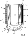
1 das Ausführungsbeispiel des erfindungsgemäßen Filters in einer seitlichen geschnittenen Darstellung;2 eine Schmutzsammelvorrichtung des Ausführungsbeispiels gemäß1 in einer perspektivischen Ansicht; und3 einen Ausschnitt des Ausführungsbeispiels gemäß1 in einer perspektivischen geschnittenen Darstellung.
-
1 the embodiment of the filter according to the invention in a lateral sectional representation;2 a dirt collecting device of the embodiment according to1 in a perspective view; and3 according to a detail of theembodiment 1 in a perspective cut representation.
Über eine Schraubverbindung 8 ist ein Filtertopf 10 am Gehäuse 1 befestigt, der einen im Wesentlichen kreiszylindrischen Hauptabschnitt 12 und einen vom Gehäuse 1 abgewandten unteren Topfboden 14 aufweist. Der Topfboden 14 hat prinzipiell eine schalenartige Form, in deren Mitte an einer tiefsten Stelle des Filtertopfes 10 eine Ablassöffnung 16 vorgesehen ist, die durch eine Verschlussschraube 18 verschlossen ist.A
Im Topfboden 14 sind am Umfang verteilt drei Vorsprünge 20 ausgebildet, von denen in
Der Vorsprung des Gehäuses 1 mit dem Ablaufkanal 28, der Ablaufraum 26, das Filterelement 22 mit der Abschlussscheibe 30, der Zulaufraum 32, die Feder 24, der Hauptabschnitt 12 und die Ablassöffnung 16 des Filtertopfes 10 sind zueinander konzentrisch angeordnet.The projection of the
Im Betrieb des erfindungsgemäßen Filters wird das verschmutzte Fluid über den Zulaufanschluss 2 zugeführt und über den Zulaufkanal 34 bzw. insbesondere über dessen Mündung in den Zulaufraum 32 in eine schraubenförmige Bewegung entlang der Innenwandung des Hauptabschnitts 12 des Filtertopfes 10 geführt. Dabei werden schwerere Schmutzpartikel über die Zentrifugalkraft nach außen zur Innenwandung des Hauptabschnitts 12 gedrängt und gelangen durch die drei Ausnehmungen 36 in den Innenraum des Topfbodens 14, wo sie gesammelt werden, bis sie durch die Ablassöffnung austreten.During operation of the filter according to the invention, the contaminated fluid is fed in via the
Das auf diese Weise vorgereinigte Fluid wird aus dem Zulaufraum 32 durch das Filterelement 22 radial nach innen in den Ablaufraum 26 gedrängt und von dort nach oben durch den Ablaufkanal 28 zum Ablaufanschluss 4 gefördert.The fluid pre-cleaned in this way is forced radially inwards from the
Erfindungsgemäß ist an der Innenwandung des Filtertopfes 10 ein Contamination-Cage bzw. eine Schmutzsammelvorrichtung 38 vorgesehen.According to the invention, a contamination cage or a
Im Innern des so gebildeten Trägergestells ist eine aus Cellulose bestehende im Wesentlichen rotationssymmetrische Schmutzsammelschicht befestigt. Dabei hängt die Schmutzsammelschicht an dem Ring 40 und ist über die Stützbeine 42 und die Fußabschnitte 44 in Umfangsrichtung gehaltert. Die Schmutzsammelschicht hat einen oberen Hauptabschnitt 46 und weist unterhalb der Fußabschnitte 44 einen verengten Abschnitt 48 auf. Unten im verengten Abschnitt 48 ist bei dem in den
Erfindungsgemäß strömt das zu reinigende Fluid spiralförmig bzw. schraubenförmig zunächst an der Innenwandung des Hauptabschnitts 12 des Filtertopfes 10 vom Zulaufkanal 34 (vgl.
Abweichend vom gezeigten Ausführungsbeispiel kann die in den Figuren gezeigte Schmutzsammelvorrichtung 38 unten geschlossen sein. Damit ist die Fläche der Schmutzsammelschicht vergrößert und die die Kapazität der Schmutzsammelvorrichtung 38 erhöht.Deviating from the exemplary embodiment shown, the
Offenbart ist ein Filter mit einem Filtertopf und einem darin aufgenommenen Filterelement, das einen äußeren Zulaufraum von einem inneren Ablaufraum trennt. Ein zu filterndes Fluid wird im Zulaufraum in einer schraubenförmigen Bahn entlang einer etwa kreiszylindrischen Innenwandung des Filtertopfes geführt. Im Zulaufraum ist eine vorzugsweise topfförmige Schmutzsammelvorrichtung angeordnet, die an der Innenwandung des Filtertopfes anliegt. Der Aufbau der genannten Bauteile ist dabei vorzugsweise im Wesentlichen konzentrisch.A filter with a filter bowl and a filter element accommodated therein, which separates an outer inlet space from an inner outlet space, is disclosed. A fluid to be filtered is guided in the inlet space in a helical path along an approximately circular-cylindrical inner wall of the filter bowl. A preferably pot-shaped dirt-collecting device is arranged in the inlet space, which rests against the inner wall of the filter pot. The structure of the components mentioned is preferably essentially concentric.
BezugszeichenlisteReference List
- 11
- Gehäusecasing
- 22
- Zulaufanschlussinlet connection
- 44
- Ablaufanschlussdrain connection
- 66
- Bypassventilbypass valve
- 88th
- Schraubverbindungscrew connection
- 1010
- Filtertopffilter pot
- 1212
- Hauptabschnittmain section
- 1414
- Topfbodenpot bottom
- 1616
- Ablassöffnungdrain hole
- 1818
- VerschlussschraubeScrew
- 2020
- Vorsprunghead Start
- 2222
- Filterelementfilter element
- 2424
- Federfeather
- 2626
- Ablaufraumdrain room
- 2828
- Ablaufkanaldrain channel
- 3030
- Abschlussscheibelens
- 3232
- Zulaufrauminlet space
- 3434
- Zulaufkanalinlet channel
- 3636
- Ausnehmungrecess
- 3838
- Schmutzsammelvorrichtungdirt collection device
- 4040
- Ringring
- 4242
- Stützbeinsupporting leg
- 4444
- Fußabschnittfoot section
- 4646
- Hauptabschnittmain section
- 4848
- verengter Abschnittnarrowed section
- 5050
- Öffnungopening
Claims (10)
Priority Applications (1)
| Application Number | Priority Date | Filing Date | Title |
|---|---|---|---|
| DE102012012143.1A DE102012012143B4 (en) | 2012-06-20 | 2012-06-20 | filter |
Applications Claiming Priority (1)
| Application Number | Priority Date | Filing Date | Title |
|---|---|---|---|
| DE102012012143.1A DE102012012143B4 (en) | 2012-06-20 | 2012-06-20 | filter |
Publications (2)
| Publication Number | Publication Date |
|---|---|
| DE102012012143A1 DE102012012143A1 (en) | 2013-12-24 |
| DE102012012143B4 true DE102012012143B4 (en) | 2022-01-13 |
Family
ID=49713540
Family Applications (1)
| Application Number | Title | Priority Date | Filing Date |
|---|---|---|---|
| DE102012012143.1A Active DE102012012143B4 (en) | 2012-06-20 | 2012-06-20 | filter |
Country Status (1)
| Country | Link |
|---|---|
| DE (1) | DE102012012143B4 (en) |
Citations (2)
| Publication number | Priority date | Publication date | Assignee | Title |
|---|---|---|---|---|
| DE102009037736A1 (en) | 2009-05-14 | 2010-11-25 | Robert Bosch Gmbh | filter |
| EP2444137A2 (en) | 2010-10-23 | 2012-04-25 | Robert Bosch GmbH | Filter housing for a filter and filter with such a filter housing |
-
2012
- 2012-06-20 DE DE102012012143.1A patent/DE102012012143B4/en active Active
Patent Citations (2)
| Publication number | Priority date | Publication date | Assignee | Title |
|---|---|---|---|---|
| DE102009037736A1 (en) | 2009-05-14 | 2010-11-25 | Robert Bosch Gmbh | filter |
| EP2444137A2 (en) | 2010-10-23 | 2012-04-25 | Robert Bosch GmbH | Filter housing for a filter and filter with such a filter housing |
Also Published As
| Publication number | Publication date |
|---|---|
| DE102012012143A1 (en) | 2013-12-24 |
Similar Documents
| Publication | Publication Date | Title |
|---|---|---|
| EP1740287B1 (en) | Fuel filter | |
| DE102005039059B3 (en) | Replaceable air-cleaning cartridge for compressed air units in cars, contains a treatment- and/or filter-material and a cyclone separator system comprising several cyclones connected in parallel and-or in series | |
| DE102011005106A1 (en) | Bypass valve, facility with bypass valve and filter element of the device | |
| EP1546513B1 (en) | Ring filter element for a liquid filter | |
| WO2011107262A1 (en) | Filter and filter element provided therefor | |
| DE10222800A1 (en) | Filters in a filter housing | |
| DE102015103619A1 (en) | Device for cleaning liquid or gaseous media and separator for the device | |
| EP2478207B1 (en) | Fuel filter of an internal combustion engine | |
| DE10327942A1 (en) | Vortex dust collector for a vacuum cleaner | |
| DE7726666U1 (en) | OIL SEPARATOR FOR AIR | |
| DE4427753A1 (en) | Oil separator | |
| DE102009025393A1 (en) | 3-stage fuel filter | |
| WO2012095124A1 (en) | Filter device | |
| DE102015003915A1 (en) | Separating element of a separating device for separating at least one fluid medium from a fluid to be treated and separating device | |
| EP3641909A1 (en) | Filter system comprising a filter element and secondary element for closing a central tube | |
| DE112019000506B4 (en) | FILTER DEVICE, PARTICULARLY FOR GAS FILTRATION | |
| DE102013012917A1 (en) | Liquid filter, in particular for fuel | |
| DE102011003645A1 (en) | Filter device for filtering liquid of internal combustion engine, particularly of motor vehicle, has filter housing with housing interior, inlet and outlet | |
| DE19757120A1 (en) | Modular fluid filter | |
| EP2808070A1 (en) | Heating filter | |
| DE102017006874B4 (en) | Ring filter element, filter device and crankcase with such a filter device | |
| EP0722760B1 (en) | Edge filter for liquids | |
| DE3248891C2 (en) | Air filter | |
| DE102012012143B4 (en) | filter | |
| DE2737135A1 (en) | LIQUID FILTER |
Legal Events
| Date | Code | Title | Description |
|---|---|---|---|
| R012 | Request for examination validly filed | ||
| R016 | Response to examination communication | ||
| R081 | Change of applicant/patentee |
Owner name: HENGST FILTRATION GMBH, DE Free format text: FORMER OWNER: ROBERT BOSCH GMBH, 70469 STUTTGART, DE |
|
| R082 | Change of representative |
Representative=s name: GLEIM PETRI PATENT- UND RECHTSANWALTSPARTNERSC, DE Representative=s name: MUELLER, CLEMENS & HACH, DE |
|
| R018 | Grant decision by examination section/examining division | ||
| R079 | Amendment of ipc main class |
Free format text: PREVIOUS MAIN CLASS: B01D0029110000 Ipc: B01D0029150000 |
|
| R020 | Patent grant now final | ||
| R082 | Change of representative |
Representative=s name: GLEIM PETRI PATENT- UND RECHTSANWALTSPARTNERSC, DE |