DE102011106981A1 - Method for manufacturing joint connection for attaching engine parts to e.g. shafts with hole, involves concentrically arranging center points with each other by immersion of shaft in bore hole of joining portion and shaft - Google Patents
Method for manufacturing joint connection for attaching engine parts to e.g. shafts with hole, involves concentrically arranging center points with each other by immersion of shaft in bore hole of joining portion and shaft Download PDFInfo
- Publication number
- DE102011106981A1 DE102011106981A1 DE201110106981 DE102011106981A DE102011106981A1 DE 102011106981 A1 DE102011106981 A1 DE 102011106981A1 DE 201110106981 DE201110106981 DE 201110106981 DE 102011106981 A DE102011106981 A DE 102011106981A DE 102011106981 A1 DE102011106981 A1 DE 102011106981A1
- Authority
- DE
- Germany
- Prior art keywords
- shaft
- joining
- joining part
- gripper
- parts
- Prior art date
- Legal status (The legal status is an assumption and is not a legal conclusion. Google has not performed a legal analysis and makes no representation as to the accuracy of the status listed.)
- Granted
Links
Images


Classifications
-
- B—PERFORMING OPERATIONS; TRANSPORTING
- B23—MACHINE TOOLS; METAL-WORKING NOT OTHERWISE PROVIDED FOR
- B23P—METAL-WORKING NOT OTHERWISE PROVIDED FOR; COMBINED OPERATIONS; UNIVERSAL MACHINE TOOLS
- B23P11/00—Connecting or disconnecting metal parts or objects by metal-working techniques not otherwise provided for
- B23P11/02—Connecting or disconnecting metal parts or objects by metal-working techniques not otherwise provided for by first expanding and then shrinking or vice versa, e.g. by using pressure fluids; by making force fits
- B23P11/025—Connecting or disconnecting metal parts or objects by metal-working techniques not otherwise provided for by first expanding and then shrinking or vice versa, e.g. by using pressure fluids; by making force fits by using heat or cold
-
- B—PERFORMING OPERATIONS; TRANSPORTING
- B21—MECHANICAL METAL-WORKING WITHOUT ESSENTIALLY REMOVING MATERIAL; PUNCHING METAL
- B21D—WORKING OR PROCESSING OF SHEET METAL OR METAL TUBES, RODS OR PROFILES WITHOUT ESSENTIALLY REMOVING MATERIAL; PUNCHING METAL
- B21D53/00—Making other particular articles
- B21D53/84—Making other particular articles other parts for engines, e.g. connecting-rods
- B21D53/845—Making camshafts
-
- F—MECHANICAL ENGINEERING; LIGHTING; HEATING; WEAPONS; BLASTING
- F16—ENGINEERING ELEMENTS AND UNITS; GENERAL MEASURES FOR PRODUCING AND MAINTAINING EFFECTIVE FUNCTIONING OF MACHINES OR INSTALLATIONS; THERMAL INSULATION IN GENERAL
- F16D—COUPLINGS FOR TRANSMITTING ROTATION; CLUTCHES; BRAKES
- F16D1/00—Couplings for rigidly connecting two coaxial shafts or other movable machine elements
- F16D1/06—Couplings for rigidly connecting two coaxial shafts or other movable machine elements for attachment of a member on a shaft or on a shaft-end
- F16D1/08—Couplings for rigidly connecting two coaxial shafts or other movable machine elements for attachment of a member on a shaft or on a shaft-end with clamping hub; with hub and longitudinal key
- F16D1/0852—Couplings for rigidly connecting two coaxial shafts or other movable machine elements for attachment of a member on a shaft or on a shaft-end with clamping hub; with hub and longitudinal key with radial clamping between the mating surfaces of the hub and shaft
- F16D1/0858—Couplings for rigidly connecting two coaxial shafts or other movable machine elements for attachment of a member on a shaft or on a shaft-end with clamping hub; with hub and longitudinal key with radial clamping between the mating surfaces of the hub and shaft due to the elasticity of the hub (including shrink fits)
-
- B—PERFORMING OPERATIONS; TRANSPORTING
- B23—MACHINE TOOLS; METAL-WORKING NOT OTHERWISE PROVIDED FOR
- B23P—METAL-WORKING NOT OTHERWISE PROVIDED FOR; COMBINED OPERATIONS; UNIVERSAL MACHINE TOOLS
- B23P2700/00—Indexing scheme relating to the articles being treated, e.g. manufactured, repaired, assembled, connected or other operations covered in the subgroups
- B23P2700/02—Camshafts
-
- F—MECHANICAL ENGINEERING; LIGHTING; HEATING; WEAPONS; BLASTING
- F01—MACHINES OR ENGINES IN GENERAL; ENGINE PLANTS IN GENERAL; STEAM ENGINES
- F01L—CYCLICALLY OPERATING VALVES FOR MACHINES OR ENGINES
- F01L1/00—Valve-gear or valve arrangements, e.g. lift-valve gear
- F01L1/02—Valve drive
- F01L1/04—Valve drive by means of cams, camshafts, cam discs, eccentrics or the like
- F01L1/047—Camshafts
Abstract
Description
Die Erfindung betrifft ein Verfahren und eine Vorrichtung zum Herstellen von Fügeverbindungen mit wenigstens zwei Bauteilen, einer Welle und Fügeteilen wie z. B. eine Bohrung aufweisende Nocken, Zahnräder, Scheiben, Räder, Lagerbuchsen oder dgl. Aus der
Aufgabe der vorliegenden Erfindung ist es, ein Verfahren und eine Vorrichtung der eingangs genannten Art zu schaffen, mit welchen die Wiederholgenauigkeit beim Fügen verbessert und der Fügeprozess optimiert wird.Object of the present invention is to provide a method and an apparatus of the type mentioned, which improves the repeatability of the joining and the joining process is optimized.
Diese Aufgabe wird durch ein Verfahren mit den Merkmalen nach Patentanspruch 1 und eine Vorrichtung zur Durchführung des Verfahrens mit den Merkmalen nach Patentanspruch 6 gelöst.This object is achieved by a method having the features of
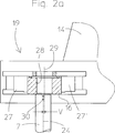
Gemäß einem vorteilhaften Aspekt der Erfindung werden die Fügeteile und die zu bestückende Welle mit einer Zentrierspitze vorzentriert. Dadurch sind die extrem engen Toleranzen, innerhalb derer das freie Wellenende und das Fügeteil relativ zueinander positioniert werden müssen, nicht mehr erforderlich. Bei einer weiteren vorteilhaften Ausführung werden jeweils zwei Fügeteile gleichzeitig gefügt. Dazu sind zwei relativ zueinander bewegliche Greifer vorgesehen, welche die Fügeteile paarweise aufnehmen und im vorgesehen Abstand auf der Welle positionieren.According to an advantageous aspect of the invention, the joining parts and the shaft to be assembled are precentered with a centering tip. As a result, the extremely tight tolerances within which the free shaft end and the joining part must be positioned relative to each other, no longer required. In a further advantageous embodiment, two joining parts are joined simultaneously. For this purpose, two grippers are provided which are movable relative to one another and which receive the parts to be joined in pairs and position them at the intended distance on the shaft.
Im Folgenden wird die Erfindung an Hand eines Ausführungsbeispiels näher beschrieben.The invention will be described in more detail below with reference to an exemplary embodiment.
Es zeigen:Show it:
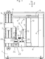
In
Abschließend wird das Fügeteil
Die
BezugszeichenlisteLIST OF REFERENCE NUMBERS
- 11
- Gestellframe
- 2 2'2 2 '
- Spannmittelclamping means
- 33
- Ständerstand
- 44
- Säulepillar
- 55
- Querträgercrossbeam
- 6 6'6 6 '
- Linearführunglinear guide
- 77
- Wellewave
- 88th
- Fügeeinrichtungjoining device
- 99
- Präzisionsführungprecision guidance
- 1010
- Fahrständertraveling column
- 1111
- Vertikalführungvertical guide
- 1212
- Schlittencarriage
- 1313
- Führungguide
- 1414
- Horizontalschlittenhorizontal slide
- 15 15'15 15 '
- Zentrierspitzecentering
- 1616
- Fügeteiladherend
- 1717
- Heizvorrichtungheater
- 1818
- Gleitführungslide
- 1919
- Greifergrab
- 2020
- Zweiter GreiferSecond gripper
- 2121
- Festanschlagfixed stop
- 2222
- Messeinrichtungmeasuring device
- 2323
- Schwenkmotorswing motor
- 2424
- Rotationsachseaxis of rotation
- 2525
- Induktorinductor
- 26 26'26 26 '
- Vertikalschlittenvertical slide
- 27 27'27 27 '
- Greiferbackegripper jaw
- 2828
- Bohrungdrilling
- 2929
- Symmetrieachseaxis of symmetry
- 3030
- Zentrierbohrungcentering
- VV
- Versatzoffset
- DD
- Außendurchmesserouter diameter
ZITATE ENTHALTEN IN DER BESCHREIBUNG QUOTES INCLUDE IN THE DESCRIPTION
Diese Liste der vom Anmelder aufgeführten Dokumente wurde automatisiert erzeugt und ist ausschließlich zur besseren Information des Lesers aufgenommen. Die Liste ist nicht Bestandteil der deutschen Patent- bzw. Gebrauchsmusteranmeldung. Das DPMA übernimmt keinerlei Haftung für etwaige Fehler oder Auslassungen.This list of the documents listed by the applicant has been generated automatically and is included solely for the better information of the reader. The list is not part of the German patent or utility model application. The DPMA assumes no liability for any errors or omissions.
Zitierte PatentliteraturCited patent literature
- EP 1392469 B1 [0001] EP 1392469 B1 [0001]
Claims (10)
Priority Applications (1)
| Application Number | Priority Date | Filing Date | Title |
|---|---|---|---|
| DE102011106981.3A DE102011106981B4 (en) | 2011-07-05 | 2011-07-05 | Method and device for producing joints |
Applications Claiming Priority (1)
| Application Number | Priority Date | Filing Date | Title |
|---|---|---|---|
| DE102011106981.3A DE102011106981B4 (en) | 2011-07-05 | 2011-07-05 | Method and device for producing joints |
Publications (2)
| Publication Number | Publication Date |
|---|---|
| DE102011106981A1 true DE102011106981A1 (en) | 2013-01-10 |
| DE102011106981B4 DE102011106981B4 (en) | 2017-01-12 |
Family
ID=47426629
Family Applications (1)
| Application Number | Title | Priority Date | Filing Date |
|---|---|---|---|
| DE102011106981.3A Expired - Fee Related DE102011106981B4 (en) | 2011-07-05 | 2011-07-05 | Method and device for producing joints |
Country Status (1)
| Country | Link |
|---|---|
| DE (1) | DE102011106981B4 (en) |
Cited By (6)
| Publication number | Priority date | Publication date | Assignee | Title |
|---|---|---|---|---|
| CN103331594A (en) * | 2013-06-22 | 2013-10-02 | 杰锋汽车动力系统股份有限公司 | Assembling device for bearing plate rotor and gear assembly of supercharger and method for assembling synchronizing gear by using assembling device |
| DE102013204116A1 (en) | 2013-03-11 | 2014-09-11 | Mahle International Gmbh | Device for positioning at least one functional element |
| WO2014161649A1 (en) * | 2013-03-30 | 2014-10-09 | Thyssenkrupp Presta Teccenter Ag | Clamping nest having fixing elements |
| DE102013109311A1 (en) * | 2013-08-28 | 2015-03-05 | Dr. Ing. H.C. F. Porsche Aktiengesellschaft | mounter |
| DE102020205267A1 (en) | 2020-04-27 | 2021-10-28 | Mahle International Gmbh | Device for positioning at least one shaft |
| DE102020213148A1 (en) | 2020-10-19 | 2022-04-21 | Mahle International Gmbh | Device for mounting a plug in a hollow shaft |
Citations (1)
| Publication number | Priority date | Publication date | Assignee | Title |
|---|---|---|---|---|
| EP1392469B1 (en) | 2001-05-29 | 2007-02-28 | Reiner Dorner | Method for fixing propulsion parts on shafts in a rotationally fixed manner |
Family Cites Families (4)
| Publication number | Priority date | Publication date | Assignee | Title |
|---|---|---|---|---|
| FR2797793B1 (en) * | 1999-08-24 | 2001-11-09 | Renault | TOOLS FOR THE MANUFACTURE OF CAMSHAFTS BY BLASTING |
| DE102004015675B4 (en) * | 2003-06-05 | 2017-07-13 | Langenstein & Schemann Gmbh | Handling device for handling a workpiece during a forming process |
| DE102007056769A1 (en) * | 2007-11-23 | 2008-06-26 | Daimler Ag | Join connection producing method for two components, particularly cam with camshaft of internal combustion engine of vehicle, involves detecting component specific measuring data of component |
| DE102007056638B4 (en) * | 2007-11-24 | 2018-02-22 | Usk Karl Utz Sondermaschinen Gmbh | Method and device for assembling a composite, in particular a camshaft and a housing |
-
2011
- 2011-07-05 DE DE102011106981.3A patent/DE102011106981B4/en not_active Expired - Fee Related
Patent Citations (1)
| Publication number | Priority date | Publication date | Assignee | Title |
|---|---|---|---|---|
| EP1392469B1 (en) | 2001-05-29 | 2007-02-28 | Reiner Dorner | Method for fixing propulsion parts on shafts in a rotationally fixed manner |
Cited By (16)
| Publication number | Priority date | Publication date | Assignee | Title |
|---|---|---|---|---|
| US9309953B2 (en) | 2013-03-11 | 2016-04-12 | Mahle International Gmbh | Device for positioning at least one functional element |
| DE102013204116A1 (en) | 2013-03-11 | 2014-09-11 | Mahle International Gmbh | Device for positioning at least one functional element |
| EP2777868A1 (en) | 2013-03-11 | 2014-09-17 | Mahle International GmbH | Device for positioning at least one functional element |
| CN104043965A (en) * | 2013-03-11 | 2014-09-17 | 马勒国际有限公司 | Device For Positioning At Least One Functional Element |
| JP2014173603A (en) * | 2013-03-11 | 2014-09-22 | Mahle Internatl Gmbh | Device for positioning at least one functional component |
| CN105102184A (en) * | 2013-03-30 | 2015-11-25 | 蒂森克虏伯普利斯坦技术中心股份公司 | Clamping nest having fixing elements |
| WO2014161649A1 (en) * | 2013-03-30 | 2014-10-09 | Thyssenkrupp Presta Teccenter Ag | Clamping nest having fixing elements |
| EP2978564B1 (en) | 2013-03-30 | 2018-03-07 | ThyssenKrupp Presta TecCenter AG | Clamping nest having fixing elements |
| US10557381B2 (en) | 2013-03-30 | 2020-02-11 | Thyssenkrupp Presta Teccenter Ag | Clamping nest having fixing elements |
| CN103331594B (en) * | 2013-06-22 | 2015-04-01 | 杰锋汽车动力系统股份有限公司 | Assembling device for bearing plate rotor and gear assembly of supercharger and method for assembling synchronizing gear by using assembling device |
| CN103331594A (en) * | 2013-06-22 | 2013-10-02 | 杰锋汽车动力系统股份有限公司 | Assembling device for bearing plate rotor and gear assembly of supercharger and method for assembling synchronizing gear by using assembling device |
| DE102013109311A1 (en) * | 2013-08-28 | 2015-03-05 | Dr. Ing. H.C. F. Porsche Aktiengesellschaft | mounter |
| DE102020205267A1 (en) | 2020-04-27 | 2021-10-28 | Mahle International Gmbh | Device for positioning at least one shaft |
| CN113635042A (en) * | 2020-04-27 | 2021-11-12 | 马勒国际有限公司 | Device for positioning at least one shaft |
| DE102020213148A1 (en) | 2020-10-19 | 2022-04-21 | Mahle International Gmbh | Device for mounting a plug in a hollow shaft |
| US11484975B2 (en) | 2020-10-19 | 2022-11-01 | Mahle International Gmbh | Method and device for mounting a plug in a hollow shaft |
Also Published As
| Publication number | Publication date |
|---|---|
| DE102011106981B4 (en) | 2017-01-12 |
Similar Documents
| Publication | Publication Date | Title |
|---|---|---|
| DE102011106981B4 (en) | Method and device for producing joints | |
| EP2237922B1 (en) | Method and apparatus for assembling a composite, in particular comprising a camshaft and a housing | |
| DE19900292C2 (en) | Universal clamping device and method for positioning and clamping for connecting rods | |
| DE60209332T2 (en) | METHOD AND DEVICE FOR PRODUCING A FORGED RACK | |
| EP2011596B1 (en) | Method and device for machining workpieces rotating around a workpiece axis | |
| EP2777868B1 (en) | Device for positioning at least one functional element and methods for thermally joining a shaft with one or more functional elements each having a hub for the shaft. | |
| EP1334784B1 (en) | Method and apparatus for assembling constructed cam shafts | |
| DE102013007072A1 (en) | A method of manufacturing a rack of an electric power steering apparatus | |
| EP3191254B1 (en) | Laser ablation and welding method for workpieces | |
| DE102009021803A1 (en) | Method and device for machining crankshafts | |
| EP3231552B1 (en) | Workpiece positioning device for a machining centre, machining centre and method | |
| EP3050663A1 (en) | Device for laser-structuring of hubs of valve drive components | |
| EP3205444B1 (en) | Device for positioning a plurality of functional elements | |
| CH672527A5 (en) | ||
| DE10024990A1 (en) | Process for inductively hardening crankshafts comprises using the central axis of the connecting peg to be hardened as the axis for the rotational movement of the crankshaft | |
| EP2477022A1 (en) | Palette system with a fitting palette and a fitting palette holder | |
| EP1434661A1 (en) | Method for loading internal high pressure forming presses and device therefor | |
| EP3162495B1 (en) | Device for heating a plurality of functional elements | |
| EP3162496B1 (en) | Device for joining a number of functional elements on a shaft | |
| DE19918272A1 (en) | Industrial robot axial movement device, with rail system and head on pivoted arm to grip fixed point | |
| EP2995417B1 (en) | Device for mounting at least one functional element with a recess for a shaft | |
| DE102013214017B3 (en) | Positioning device for positioning workpieces, machine tool with such a positioning device, method for positioning workpieces | |
| DE102017101579A1 (en) | Workpiece clamping system for a measuring machine | |
| DE10126004A1 (en) | Transfer machine has several workstations, drive arrangement for stepwise rotation of rotary table in one direction and continuous rotation without stopping in opposite direction | |
| EP1392469B1 (en) | Method for fixing propulsion parts on shafts in a rotationally fixed manner |
Legal Events
| Date | Code | Title | Description |
|---|---|---|---|
| R012 | Request for examination validly filed | ||
| R016 | Response to examination communication | ||
| R016 | Response to examination communication | ||
| R018 | Grant decision by examination section/examining division | ||
| R026 | Opposition filed against patent | ||
| R119 | Application deemed withdrawn, or ip right lapsed, due to non-payment of renewal fee | ||
| R452 | Opposition proceedings concluded by decision of the patent division/the federal patent court | ||
| R453 | Decision of the patent division/the federal patent court on the conclusion of the opposition proceedings has become final |