DE102011088301A1 - Haptic accelerator pedal with DC motor operated actuator and method for controlling a haptic accelerator pedal - Google Patents
Haptic accelerator pedal with DC motor operated actuator and method for controlling a haptic accelerator pedal Download PDFInfo
- Publication number
- DE102011088301A1 DE102011088301A1 DE201110088301 DE102011088301A DE102011088301A1 DE 102011088301 A1 DE102011088301 A1 DE 102011088301A1 DE 201110088301 DE201110088301 DE 201110088301 DE 102011088301 A DE102011088301 A DE 102011088301A DE 102011088301 A1 DE102011088301 A1 DE 102011088301A1
- Authority
- DE
- Germany
- Prior art keywords
- actuator
- pedal
- accelerator pedal
- pedal element
- haptic accelerator
- Prior art date
- Legal status (The legal status is an assumption and is not a legal conclusion. Google has not performed a legal analysis and makes no representation as to the accuracy of the status listed.)
- Withdrawn
Links
Images

Classifications
-
- B—PERFORMING OPERATIONS; TRANSPORTING
- B60—VEHICLES IN GENERAL
- B60K—ARRANGEMENT OR MOUNTING OF PROPULSION UNITS OR OF TRANSMISSIONS IN VEHICLES; ARRANGEMENT OR MOUNTING OF PLURAL DIVERSE PRIME-MOVERS IN VEHICLES; AUXILIARY DRIVES FOR VEHICLES; INSTRUMENTATION OR DASHBOARDS FOR VEHICLES; ARRANGEMENTS IN CONNECTION WITH COOLING, AIR INTAKE, GAS EXHAUST OR FUEL SUPPLY OF PROPULSION UNITS IN VEHICLES
- B60K26/00—Arrangements or mounting of propulsion unit control devices in vehicles
- B60K26/02—Arrangements or mounting of propulsion unit control devices in vehicles of initiating means or elements
- B60K26/021—Arrangements or mounting of propulsion unit control devices in vehicles of initiating means or elements with means for providing feel, e.g. by changing pedal force characteristics
- B60K2026/023—Arrangements or mounting of propulsion unit control devices in vehicles of initiating means or elements with means for providing feel, e.g. by changing pedal force characteristics with electrical means to generate counter force or torque
Abstract
Es wird ein haptisches Fahrpedal (11) für ein Kraftfahrzeug (1) sowie ein Verfahren zum Steuern eines haptischen Fahrpedals (11) vorgeschlagen. Ein Pedalelement (5) wird von einem Aktuator (13), der über ein durch einen Motor (23) verlagerbares Betätigungselement (27) mit dem Pedalelement (5) zusammenwirken kann, mit einer Kraft entgegen einer Betätigungsrichtung (7) beaufschlagt. Als Motor (23) wird hierbei ein Gleichstrommotor eingesetzt, der über ein Getriebe (25) mit dem Betätigungselement (27) gekoppelt ist. Mit Hilfe des Gleichstrommotors und des Getriebes können hohe Kräfte bei gleichzeitig kleiner Bauweise und geringen Material- und Herstellungskosten erreicht werden. Der Aktuator (13) des haptischen Fahrpedals (11) kann über eine Steuerung (3) derart angesteuert werden, dass außerhalb einer Signalphase, in der eine Gegenkraft auf das Pedalelement (5) ausgeübt werden soll, eine Wirkverbindung zwischen dem Pedalelement (5) und dem Aktuator (13) getrennt wird. Vorzugsweise wird der Aktuator (13) dann in eine Ruhelage verfahren, wo er ohne Energiebedarf warten kann, bis er kurz vor einer nächsten Signalphase in eine Wartelage verfahren wird, in der er schnell wieder mit dem Pedalelement in Eingriff kommen kann und so das haptisch wahrnehmbare Signal kurzfristig erzeugt werden kann. Auf diese Weise können ein geringer Energieverbrauch und eine kurze Reaktionszeit miteinander kombiniert werden.A haptic accelerator pedal (11) for a motor vehicle (1) and a method for controlling a haptic accelerator pedal (11) are proposed. A pedal element (5) is acted on by an actuator (13), which can interact with the pedal element (5) via an actuating element (27) displaceable by a motor (23), with a force against an actuation direction (7). As a motor (23) in this case a DC motor is used, which is coupled via a transmission (25) with the actuating element (27). With the help of the DC motor and the gearbox high forces can be achieved at the same time small size and low material and manufacturing costs. The actuator (13) of the haptic accelerator pedal (11) can be controlled via a controller (3) such that outside a signal phase in which a counterforce is to be exerted on the pedal element (5), an operative connection between the pedal element (5) and the actuator (13) is disconnected. Preferably, the actuator (13) is then moved to a rest position where it can wait without energy until it is moved shortly before a next signal phase in a waiting position in which he can quickly get back into engagement with the pedal element and so the haptic perceptible Signal can be generated at short notice. In this way, a low energy consumption and a short reaction time can be combined.
Description
Gebiet der ErfindungField of the invention
Die vorliegende Erfindung betrifft ein haptisches Fahrpedal in einem Kraftfahrzeug sowie ein Verfahren zum Steuern eines haptischen Fahrpedals. Die Erfindung betrifft ferner eine entsprechend ausgebildete Steuerung und ein Computerprogrammprodukt, das bei Ausführung auf einem programmierbaren Steuergerät das erfindungsgemäße Verfahren ausführen soll, sowie ein computerlesbares Medium, auf dem ein solches Computerprogrammprodukt gespeichert ist.The present invention relates to a haptic accelerator pedal in a motor vehicle and to a method for controlling a haptic accelerator pedal. The invention further relates to a correspondingly formed controller and a computer program product which, when executed on a programmable controller, is to execute the method according to the invention, as well as a computer-readable medium on which such a computer program product is stored.
Stand der TechnikState of the art
In modernen Kraftfahrzeugen wird der Fahrer durch eine Vielzahl von zur Verfügung gestellten Informationen beim Führen des Fahrzeugs unterstützt. Beispielsweise kann es hilfreich sein, dem Fahrer Rückmeldungen über bestimmte Fahrzustände in Form von Signalen zu geben, um die Sicherheit beim Fahren oder den Komfort des Fahrers erhöhen zu können oder um Treibstoff einsparen zu können. Diese Rückmeldungen können auf verschiedene Weise wie zum Beispiel optisch oder akustisch bereitgestellt werden.In modern motor vehicles, the driver is supported by a variety of information provided while driving the vehicle. For example, it may be helpful to give the driver feedback about certain driving conditions in the form of signals in order to increase the safety when driving or the comfort of the driver or to save fuel. These feedbacks can be provided in various ways, such as optically or acoustically.
In modernen Fahrzeugen werden zusätzlich auch Möglichkeiten der haptischen Rückmeldung an den Fahrer über das Fahrpedal des Fahrzeugs implementiert. Das Fahrpedal ist hierzu mit einem Aktuator ausgestattet, der es ermöglicht, das Fahrpedal gezielt mit einer Kraft zu beaufschlagen. Beispielsweise kann das Fahrpedal während einer Signalphase mit Hilfe einer von dem Aktuator erzeugten variierenden Kraft in Schwingungen versetzt werden, die von dem Fahrer als Vibrationen oder Pulsationen über seinen auf dem Fahrpedal ruhenden Fuß haptisch wahrgenommen werden können. Alternativ kann der Aktuator eine Gegenkraft auf das Fahrpedal ausüben, die ein Niederdrücken des Fahrpedals beispielsweise ab einer bestimmten Pedalstellung erschwert, um so einen haptische wahrnehmbaren variablen Druckpunkt darzustellen. In modern vehicles, additional possibilities of haptic feedback to the driver via the accelerator pedal of the vehicle are implemented. The accelerator pedal is equipped for this purpose with an actuator, which makes it possible to apply the accelerator pedal specifically with a force. For example, the accelerator pedal during a signal phase with the aid of a varying force generated by the actuator can be vibrated, which can be perceived by the driver as vibrations or pulsations on his resting on the accelerator pedal foot tactile. Alternatively, the actuator can exert a counterforce on the accelerator pedal, which makes it difficult to depress the accelerator pedal, for example from a certain pedal position, so as to represent a haptic perceptible variable pressure point.
Auf diese Weise können dem Fahrer durch dessen haptische Wahrnehmung Hinweise und Warnungen mitgeteilt oder auch Komfortfunktionen bereitgestellt werden, ohne dass dieser durch optische oder akustische Signale beispielsweise vom Beobachten des Verkehrs abgelenkt würde.In this way, the driver can be informed by the haptic perception hints and warnings or comfort functions are provided without this would be distracted by visual or audible signals, for example, from observing the traffic.
Offenbarung der ErfindungDisclosure of the invention
Die vorliegende Erfindung ermöglicht in ihren Ausführungsformen eine vorteilhafte Ausgestaltung eines haptischen Fahrpedals in einem Kraftfahrzeug sowie ein vorteilhaftes Ansteuern eines haptischen Fahrpedals. Dabei können Gewicht, Baugröße sowie eventuell Kosten für das Fahrpedal aufgrund der strukturellen Ausgestaltung seiner Komponenten im Vergleich zu herkömmlichen haptischen Fahrpedalen gesenkt werden. Außerdem können im Betrieb des haptischen Fahrpedals ein Energieverbrauch sowie eventuell Verschleißerscheinungen gesenkt werden. The present invention allows in their embodiments an advantageous embodiment of a haptic accelerator pedal in a motor vehicle and an advantageous driving a haptic accelerator pedal. In this case, weight, size and possibly costs for the accelerator pedal due to the structural design of its components can be reduced compared to conventional haptic accelerator pedals. In addition, in the operation of the haptic accelerator pedal energy consumption and any signs of wear can be reduced.
Das vorgeschlagene haptische Fahrpedal weist ein Pedalelement sowie einen Aktuator auf. Das Pedalelement kann von einer Ruhestellung aus in einer Betätigungsrichtung hin zu einer maximal betätigten Stellung bewegt werden. Der Aktuator, der über ein durch einen Motor verlagerbares Betätigungselement mit dem Pedalelement zusammenwirken kann, kann über das Betätigungselement eine Kraft entgegen der Betätigungsrichtung auf das Pedalelement ausüben. Der Motor des Aktuators ist hierbei ein Gleichstrommotor und ist über ein Getriebe mit dem Betätigungselement gekoppelt.The proposed haptic accelerator pedal has a pedal element and an actuator. The pedal element can be moved from a rest position in an actuating direction towards a maximum actuated position. The actuator, which can interact with the pedal element via an actuating element displaceable by a motor, can exert a force against the actuating direction on the pedal element via the actuating element. The motor of the actuator here is a DC motor and is coupled via a transmission with the actuator.
Ideen zu dem hier vorgeschlagenen haptischen Fahrpedal können u. a. als auf den folgenden Erkenntnissen beruhend angesehen werden: Um die zur Erzeugung von haptisch wahrnehmbaren Signalen notwendigen hohen Kräfte von beispielsweise 20 bis 100 Newton auf ein Pedalelement eines Fahrpedals übertragen zu können, wurden bei herkömmlichen haptischen Fahrpedalen in der Regel Direktantriebe eingesetzt. Solche als Direktantrieb verwendete Motoren sind im Allgemeinen entweder schwer und benötigen eine große Baugröße oder sind kompakt, benötigen jedoch zur Erzeugung eines hohen Drehmomentes aus kleinem Bauraum spezielle Magneten, beispielsweise aus Seltene-Erde-Materialien. Diese sind jedoch teuer. Außerdem müssen sie mit hohen Stromstärken von beispielsweise mehreren Ampere angesteuert werden. Ideas for the here proposed haptic accelerator pedal u. a. be regarded as based on the following findings: In order to transmit the necessary for the production of haptic perceptible signals high forces of, for example, 20 to 100 Newton on a pedal element of an accelerator pedal, direct drives have been used in conventional haptic accelerator pedals in the rule. Such direct drive motors are generally either heavy and require a large size or are compact, but require special magnets, such as rare earth materials, to produce high torque from a small space. These are expensive. In addition, they must be driven with high currents of, for example, several amps.
Trotz dieser Nachteile wurde bisher davon ausgegangen, dass ausreichend hohe Kräfte in den zur Erzeugung eines haptischen Signals notwendigen kurzen Zeitdauern nur durch Direktantriebe, wie z.B. durch Torquer-Motoren, generiert werden können.Despite these drawbacks, it has heretofore been assumed that sufficiently high forces in the short durations necessary to produce a haptic signal can only be achieved by direct drives, e.g. can be generated by Torquer motors.
Es wird nun vorgeschlagen, den Torquer-Motor durch einen Gleichstrommotor zu ersetzen. Um die nötigen Kräfte zu erzeugen, wird dem Gleichstrommotor ein Getriebe nachgeschaltet, welches wiederum mit einem Betätigungselement gekoppelt ist, das mit dem Pedalelement des Fahrpedals in Wirkverbindung treten und die Kräfte von dem Gleichstrommotor auf das Pedalelement übertragen kann.It is now proposed to replace the Torquer motor by a DC motor. In order to generate the necessary forces, the DC motor, a transmission is connected downstream, which in turn is coupled to an actuating element which is connected to the pedal element of the accelerator pedal in Actively connect and the forces can be transmitted from the DC motor to the pedal element.
Gleichstrommotoren können im Gegensatz z.B. zu Torquer-Motoren Drehmoment uneingeschränkt über dem Drehwinkel der Motorachse erzeugen. Damit ist es für Gleichstrommotoren möglich, mittels eines Zahnradgetriebes und entsprechenden Übersetzungsstufen das Motor-Drehmoment auf wesentlich größere Werte zu bringen. Auf diese Weise kann ein baukleinerer Gleichstrommotor bei signifikant geringerer Stromaufnahme und kleinerem Gewicht das Drehmoment, wie es bisher von einem Torquer Motor erzeugt wurde, bereitstellen.DC motors, in contrast, e.g. to Torquer motors produce torque unrestricted over the rotation angle of the motor axis. This makes it possible for DC motors, by means of a gear transmission and corresponding gear ratios to bring the engine torque to much greater values. In this way, a smaller DC motor with significantly lower power consumption and smaller weight, the torque, as it was previously produced by a Torquer motor provide.
Das Betätigungselement und das Pedalelement sind dabei vorzugsweise derart ausgestaltet, dass der Aktuator über das Betätigungselement ausschließlich eine Kraft entgegen der Betätigungsrichtung, d. h. entgegen der Richtung, in der das Pedalelement von dem Fahrer aus der Ruhestellung hin zu einer maximal betätigten Stellung niedergedrückt werden kann, auf das Pedalelement ausüben kann. Mit anderen Worten sollen das Betätigungselement und das Pedalelement beispielsweise nur so gekoppelt sein, dass eine Kraft von dem Betätigungselement auf das Pedalelement nur in einer Richtung ausgeübt werden kann, beispielsweise nur als Druck oder alternativ nur als Zug, in der entgegengesetzten Richtung jedoch keine Kraftübertragung möglich ist. Hierdurch kann sichergestellt werden, dass der Aktuator zwar eine dem Niederdrücken des Pedalelements entgegengerichtete Gegenkraft hin zu der Ruhestellung auf das Pedalelement ausüben kann, das Pedalelement von dem Aktuator jedoch nicht aus seiner Ruhestellung heraus bewegt werden kann.The actuating element and the pedal element are preferably designed such that the actuator via the actuating element only a force against the operating direction, d. H. against the direction in which the pedal member can be depressed by the driver from the rest position to a maximum actuated position, can exert on the pedal element. In other words, for example, the actuating element and the pedal element should only be coupled in such a way that a force can be exerted by the actuating element on the pedal element only in one direction, for example only as pressure or alternatively only as a train, but in the opposite direction no power transmission is possible is. In this way it can be ensured that the actuator can indeed exert a counterforce directed counter to the depression of the pedal element towards the rest position on the pedal element, but the pedal element can not be moved out of its rest position by the actuator.
Um einerseits ausreichend hohe Gegenkräfte auf das Pedalelement ausüben zu können und um andererseits das Betätigungselement schnell verstellen zu können, kann das Getriebe des Aktuators zweistufig ausgebildet sein.On the one hand to be able to exert sufficiently high opposing forces on the pedal element and on the other hand to be able to quickly adjust the actuating element, the transmission of the actuator may be formed in two stages.
Da eine elektrische Stromaufnahme für einen Gleichstrommotor mit Getriebe in einem Aktuator wesentlich geringer sein kann, als für die herkömmlich verwendeten Direkt-Antriebe und damit die verbundene Verlustleistung ebenfalls gering bleiben kann, kann eine zur Ansteuerung des Aktuators verwendete Elektronik einer Steuerung z.B. in einem ohnehin vorhandenen Motorsteuergerät des Kraftfahrzeugs integriert werden. Damit kann ein zusätzliches Steuergerät, das lediglich für die Ansteuerung des haptischen Fahrpedals zuständig ist, überflüssig werden.Since an electrical current consumption for a DC motor with gearbox in an actuator can be substantially lower than for the conventionally used direct drives and thus the associated power loss can also remain low, an electronics used to drive the actuator of a controller, for example. be integrated in an already existing engine control unit of the motor vehicle. Thus, an additional control unit, which is responsible only for the control of the haptic accelerator pedal, become superfluous.
Es wird ferner ein Verfahren zum Steuern eines haptischen Fahrpedals vorgeschlagen. Dabei wird ein Pedalelement während einer Signalphase mit einer von einem Aktuator erzeugten Gegenkraft beaufschlagt. Die Gegenkraft wirkt dabei entgegen einer Betätigungsrichtung, in der das Pedalelement von einer Nullstellung aus hin zu einer maximal betätigten Stellung bewegt werden kann. Außerhalb der Signalphase wird der Aktuator dabei derart angesteuert, dass eine Wirkverbindung zwischen dem Pedalelement und dem Aktuator getrennt wird.A method for controlling a haptic accelerator pedal is also proposed. In this case, a pedal element is acted upon during a signal phase with an opposing force generated by an actuator. The counterforce acts counter to an actuation direction in which the pedal element can be moved from a zero position to a maximum actuated position. Outside the signal phase, the actuator is driven in such a way that an operative connection between the pedal element and the actuator is disconnected.
Mit anderen Worten können das Pedalelement und der Aktuator derart ausgelegt und angeordnet sein, dass es zumindest bei Betätigung des Aktuators in eine bestimmte Richtung zu einer Trennung einer Wirkverbindung zwischen dem Aktuator und dem Pedalelement kommt, während bei Betätigung des Aktuators in die andere Richtung eine solche Wirkverbindung hergestellt oder beibehalten werden kann und somit eine Kraft von dem Aktuator auf das Pedalelement übertragen werden kann. In other words, the pedal element and the actuator can be designed and arranged such that, at least when the actuator is actuated in a certain direction, a separation of an operative connection between the actuator and the pedal element occurs, whereas when the actuator is actuated in the other direction Active connection can be made or maintained and thus a force can be transmitted from the actuator to the pedal element.
Es wird dabei nun vorgeschlagen, den Aktuator derart anzusteuern, dass die Wirkverbindung zwischen dem Pedalelement und dem Aktuator im Wesentlichen nur während der eigentlichen Signalphase, in der die Gegenkraft zum Erzeugen des haptisch wahrnehmbaren Signals auf das Pedalelement ausgeübt werden soll, hergestellt wird. Außerhalb der Signalphase soll der Aktuator von dem Pedalelement getrennt sein und dieses nicht direkt beeinflussen können. Dadurch kann erreicht werden, dass sich das haptische Fahrpedal außerhalb einer Signalphase wie ein herkömmliches Fahrpedal verhalten kann, ohne dass ein Fahrer haptisch Einflüsse durch einen mit dem Pedalelement gekoppelten Aktuator spüren kann. Außerdem kann ein Energieverbrauch des Aktuators gering gehalten werden, da außerhalb der Signalphasen lediglich kurzzeitig Energie benötigt wird, um den Aktuator von dem Pedalelement zu trennen, und anschließend der Aktuator ohne weiteren Energieaufwand ruhen kann.It is now proposed to control the actuator such that the operative connection between the pedal element and the actuator essentially only during the actual signal phase in which the counterforce for generating the haptic perceptible signal is to be exerted on the pedal element, is produced. Outside the signal phase, the actuator should be disconnected from the pedal element and not be able to directly influence it. It can thereby be achieved that the haptic accelerator pedal can behave outside a signal phase like a conventional accelerator pedal, without a driver being able to feel haptically influences by an actuator coupled to the pedal element. In addition, power consumption of the actuator can be kept low, since outside the signal phases only briefly energy is needed to disconnect the actuator of the pedal element, and then the actuator can rest without further energy.
Der Aktuator kann nach einer Signalphase derart angesteuert werden, dass er eine Ruhelage einnimmt, in der für keine der von dem Pedalelement einnehmbaren Positionen eine Wirkverbindung zwischen dem Pedalelement und dem Aktuator auftritt. After a signal phase, the actuator can be triggered in such a way that it assumes a rest position in which no operative connection between the pedal element and the actuator occurs for any of the positions that can be taken up by the pedal element.
Mit anderen Worten kann das Betätigungselement des Aktuators im Anschluss an eine Signalphase in eine Position verfahren werden, in der es nicht mit dem Pedalelement zusammenwirkt, unabhängig davon, welche Lage das Pedalelement einnimmt. Der Aktuator braucht dabei lediglich einmalig nach Abschluss der Signalphase in die Ruhelage verfahren werden und kann dort ohne weiteren Energiebedarf verharren, bis eine neue Signalphase beginnen soll und der Aktuator wieder in Wirkverbindung mit dem Pedalelement treten soll.In other words, the actuator of the actuator can be moved following a signal phase in a position in which it does not interact with the pedal element, regardless of which position the pedal element occupies. The actuator needs to be moved only once after completion of the signal phase in the rest position and can remain there without further energy requirements until a new signal phase should begin and the actuator should again be in operative connection with the pedal element.
Der Aktuator kann dabei in einer Vorbereitungsphase vor einer Signalphase derart angesteuert werden, dass er eine Wartelage einnimmt, in der zwar keine Wirkverbindung zwischen dem Pedalelement und dem Aktuator herrscht, von der aus der Aktuator aber kurzfristiger in eine Wirkverbindung mit dem Pedalelement eintreten kann, als dies aus der Ruhelage der Fall wäre. The actuator can in a preparatory phase before a signal phase in such a way be controlled that he occupies a waiting position, in which there is no operative connection between the pedal element and the actuator, but from which the actuator can enter into an operative connection with the pedal element for a short time, as would be the case from the rest position.
Die Wartelage kann dabei beispielsweise so gewählt sein, dass das Betätigungselement des Aktuators dem Pedalelement näher liegt, als dies in der Ruhelage der Fall ist und somit schneller in einen mechanischen Eingriff mit dem Pedalelement verfahren werden kann. Eine den Aktuator steuernde Steuerung kann dabei z. B. feststellen, dass in naher Zukunft, beispielsweise innerhalb der nachfolgenden 200 Millisekunden, ein haptisch wahrnehmbares Signal erzeugt werden soll und in Vorbereitung der Erzeugung dieses Signals den Aktuator bereits in die Wartelage verlagern, um dann möglichst kurzfristig die Wirkverbindung zwischen dem Aktuator und dem Pedalelement bewirken zu können.The waiting position can be chosen, for example, so that the actuating element of the actuator is closer to the pedal element, as is the case in the rest position and thus can be moved faster into mechanical engagement with the pedal element. A controller controlling the controller can be z. B. notice that in the near future, for example, within the subsequent 200 milliseconds, a haptic perceptible signal to be generated and in preparation for the generation of this signal, the actuator already in the waiting position, then as short as possible, the operative connection between the actuator and the pedal element to be able to effect.
Die Wartelage braucht hierbei nicht statisch zu sein, sondern kann einer aktuellen Position des Pedalelements nachgeführt werden. Hierzu kann beispielsweise ein Sensor die aktuelle Position des Pedalelements erfassen und eine geeignete Regelung die Anordnung des Aktuators geeignet der aktuellen Position des Pedalelements nachführen. Die Nachführung kann so geregelt werden, dass während der Vorbereitungsphase noch kein Eingriff zwischen dem Aktuator und dem Pedalelement stattfindet, um störende Einflussfaktoren auf das Fahrpedal auszuschließen, der Aktuator während der Vorbereitungsphase jedoch immer so angeordnet ist, dass sehr kurzfristig, beispielsweise innerhalb weniger Millisekunden, eine Wirkverbindung mit dem Pedalelement hergestellt werden kann und auf diese Weise schnell ein haptisch wahrnehmbares Signal erzeugt werden kann.The waiting position need not be static, but can be tracked a current position of the pedal element. For this purpose, for example, a sensor detect the current position of the pedal element and a suitable control track the arrangement of the actuator suitable for the current position of the pedal element. The tracking can be controlled so that during the preparation phase still no engagement between the actuator and the pedal element takes place to exclude disturbing factors on the accelerator pedal, the actuator during the preparation phase, however, always arranged so that very short, for example within a few milliseconds, an operative connection with the pedal element can be made and in this way a haptic perceptible signal can be generated quickly.
Die oben beschriebenen Ausführungsformen von erfindungsgemäßen Verfahren und die damit erreichbaren Funktionalitäten und Vorteile können durch eine in einem Fahrzeug vorgesehene Steuerung zum Steuern des haptischen Fahrpedals implementiert werden.The above-described embodiments of methods according to the invention and the functionalities and advantages that can be achieved therewith can be implemented by a controller provided in a vehicle for controlling the haptic accelerator pedal.
Die Steuerung kann dabei dazu ausgelegt sein, über geeignete Schnittstellen Steuersignale an einen in dem Aktuator enthaltenen Antriebsmotor auszugeben. Außerdem kann die Steuerung Schnittstellen aufweisen, um beispielsweise von geeigneten Sensoren Informationen über die aktuelle Position des Aktuators, des Fahrpedals und/oder auf das Fahrpedal ausgeübte Kräfte empfangen zu können. The controller can be designed to output control signals to a drive motor contained in the actuator via suitable interfaces. In addition, the controller may have interfaces in order, for example, to be able to receive information about the current position of the actuator, the accelerator pedal and / or forces exerted on the accelerator pedal by suitable sensors.
Die Steuerung kann das vorgeschlagene Steuerverfahren sowie etwaige Informationsauswertungen von Sensorsignalen in Hardware und/oder in Software implementieren. Es kann vorteilhaft sein, eine programmierbare Steuerung für die Ausführung des oben beschriebenen Verfahrens zu programmieren. Hierzu kann ein Computerprogrammprodukt computerlesbare Anweisungen aufweisen, die die programmierbare Steuerung dazu anweisen, die Schritte des jeweiligen Verfahrens durchzuführen. Das Computerprogrammprodukt kann auf einem computerlesbaren Medium wie beispielsweise einer CD, einer DVD, einem Flashspeicher, ROM, EPROM oder ähnlichem gespeichert sein. Um die von dem Aktuator zu bewirkende Kraft bzw. dessen Anordnung korrekt ansteuern zu können, kann neben einer Verarbeitung weiterer Sensordaten auch in einer Datenbank oder in Form von Kennlinien gespeicherte Information über eine von dem Aktuator bewirkte Reaktion auf bestimmte Steuerungssignale herangezogen werden. The controller may implement the proposed control method as well as any informational evaluation of sensor signals in hardware and / or in software. It may be advantageous to program a programmable controller for carrying out the method described above. For this purpose, a computer program product may have computer-readable instructions instructing the programmable controller to perform the steps of the respective method. The computer program product may be stored on a computer readable medium such as a CD, a DVD, a flash memory, ROM, EPROM or the like. In order to be able to correctly control the force or its arrangement to be effected by the actuator, in addition to a processing of further sensor data, information stored about a response of the actuator to certain control signals can also be used in a database or in the form of characteristic curves.
Es wird angemerkt, dass mögliche Merkmale und Vorteile von Ausführungsformen der Erfindung hierin teilweise mit Bezug auf ein erfindungsgemäßes Verfahren und teilweise mit Bezug auf ein erfindungsgemäßes haptisches Fahrpedal oder eine Steuerung beschrieben sind. Ein Fachmann wird erkennen, dass die einzelnen Merkmale in geeigneter Weise miteinander kombiniert oder ausgetauscht werden können, insbesondere von dem haptischen Fahrpedal bzw. der Steuerung auf das Verfahren und umgekehrt übertragen werden können, um auf diese Weise zu weiteren Ausführungsformen und möglicherweise Synergieeffekten zu gelangen.It is noted that possible features and advantages of embodiments of the invention herein are described in part with reference to a method according to the invention and in part with reference to a haptic accelerator pedal or a control according to the invention. A person skilled in the art will recognize that the individual features can be suitably combined or exchanged with one another, in particular can be transferred from the haptic accelerator pedal or the control to the method and vice versa, thus leading to further embodiments and possibly synergy effects.
Kurze Beschreibung der ZeichnungenBrief description of the drawings
Nachfolgend werden Ausführungsformen der Erfindung mit Bezug auf die beigefügten Zeichnungen beschrieben. Weder die Beschreibung noch die Zeichnungen sollen dabei als die Erfindung einschränkend ausgelegt werden. Hereinafter, embodiments of the invention will be described with reference to the accompanying drawings. Neither the description nor the drawings are intended to be construed as limiting the invention.
Die Zeichnungen sind lediglich schematisch und nicht maßstabsgetreu.The drawings are only schematic and not to scale.
Ausführungsformen der ErfindungEmbodiments of the invention
Das Fahrpedal
Der Aktuator
Der Aktuator
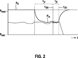
Eine Funktionsweise der Steuerung
Solange kein haptisch wahrnehmbares Signal erzeugt werden soll, steuert das Steuergerät
Kurz bevor ein haptisch wahrnehmbares Signal erzeugt werden soll, z.B. 100ms vor einem Beginn tS0 einer Signalphase tS, steuert die Steuerung
Erst wenn tatsächlich ein haptisch wahrnehmbares Signal erzeugt werden soll, das heißt, am Beginn tS0 einer Signalphase tS, steuert das Steuergerät
Sobald der Aktuator
Nach dem Ende tS1 der Signalphase tS lässt die Steuerung
ZITATE ENTHALTEN IN DER BESCHREIBUNG QUOTES INCLUDE IN THE DESCRIPTION
Diese Liste der vom Anmelder aufgeführten Dokumente wurde automatisiert erzeugt und ist ausschließlich zur besseren Information des Lesers aufgenommen. Die Liste ist nicht Bestandteil der deutschen Patent- bzw. Gebrauchsmusteranmeldung. Das DPMA übernimmt keinerlei Haftung für etwaige Fehler oder Auslassungen.This list of the documents listed by the applicant has been generated automatically and is included solely for the better information of the reader. The list is not part of the German patent or utility model application. The DPMA assumes no liability for any errors or omissions.
Zitierte PatentliteraturCited patent literature
- DE 2555429 [0005] DE 2555429 [0005]
Claims (13)
Priority Applications (5)
| Application Number | Priority Date | Filing Date | Title |
|---|---|---|---|
| DE201110088301 DE102011088301A1 (en) | 2011-12-12 | 2011-12-12 | Haptic accelerator pedal with DC motor operated actuator and method for controlling a haptic accelerator pedal |
| JP2014546374A JP6073361B2 (en) | 2011-12-12 | 2012-10-19 | Tactile accelerator pedal provided with actuator driven by DC motor, and control method of tactile accelerator pedal |
| EP12778292.8A EP2790949A1 (en) | 2011-12-12 | 2012-10-19 | Haptic gas pedal comprising a dc motor-driven actuator, and method for controlling a haptic gas pedal |
| PCT/EP2012/070722 WO2013087267A1 (en) | 2011-12-12 | 2012-10-19 | Haptic gas pedal comprising a dc motor-driven actuator, and method for controlling a haptic gas pedal |
| KR1020147015668A KR20140101766A (en) | 2011-12-12 | 2012-10-19 | Haptic gas pedal comprising a dc motor-driven actuator, and method for controlling a haptic gas pedal |
Applications Claiming Priority (1)
| Application Number | Priority Date | Filing Date | Title |
|---|---|---|---|
| DE201110088301 DE102011088301A1 (en) | 2011-12-12 | 2011-12-12 | Haptic accelerator pedal with DC motor operated actuator and method for controlling a haptic accelerator pedal |
Publications (1)
| Publication Number | Publication Date |
|---|---|
| DE102011088301A1 true DE102011088301A1 (en) | 2013-06-13 |
Family
ID=47076194
Family Applications (1)
| Application Number | Title | Priority Date | Filing Date |
|---|---|---|---|
| DE201110088301 Withdrawn DE102011088301A1 (en) | 2011-12-12 | 2011-12-12 | Haptic accelerator pedal with DC motor operated actuator and method for controlling a haptic accelerator pedal |
Country Status (5)
| Country | Link |
|---|---|
| EP (1) | EP2790949A1 (en) |
| JP (1) | JP6073361B2 (en) |
| KR (1) | KR20140101766A (en) |
| DE (1) | DE102011088301A1 (en) |
| WO (1) | WO2013087267A1 (en) |
Cited By (2)
| Publication number | Priority date | Publication date | Assignee | Title |
|---|---|---|---|---|
| DE102014006438A1 (en) | 2014-05-02 | 2015-11-05 | Daimler Ag | Pedal device for a motor vehicle |
| DE102015007584A1 (en) * | 2015-06-16 | 2016-12-22 | Audi Ag | Active accelerator pedal for a vehicle |
Families Citing this family (2)
| Publication number | Priority date | Publication date | Assignee | Title |
|---|---|---|---|---|
| US9459649B2 (en) | 2013-03-15 | 2016-10-04 | Cts Corporation | Active force pedal assembly |
| US9311791B2 (en) | 2013-08-23 | 2016-04-12 | Raytheon Canada Limited | Tactile feel control device |
Citations (1)
| Publication number | Priority date | Publication date | Assignee | Title |
|---|---|---|---|---|
| DE2555429A1 (en) | 1975-12-10 | 1977-06-16 | Bosch Gmbh Robert | Tactile warning signal for driver - uses vibrator on throttle pedal when selected parameter reaches danger level |
Family Cites Families (7)
| Publication number | Priority date | Publication date | Assignee | Title |
|---|---|---|---|---|
| JP2000054860A (en) * | 1998-08-10 | 2000-02-22 | Denso Corp | Automatic traveling control device, pedal reaction regulator and recording medium |
| DE19916434B4 (en) * | 1999-04-12 | 2006-04-06 | Deutsches Zentrum für Luft- und Raumfahrt e.V. | Electromechanically driven swiveling pedal |
| DE10251035A1 (en) * | 2002-11-02 | 2004-05-19 | Robert Bosch Gmbh | Pedal assembly |
| DE102009045710A1 (en) * | 2008-10-21 | 2010-04-22 | Continental Teves Ag & Co. Ohg | Method and device for controlling an accelerator pedal |
| JP5276479B2 (en) * | 2009-03-06 | 2013-08-28 | 本田技研工業株式会社 | Vehicle driving support device |
| DE102009021585A1 (en) * | 2009-05-15 | 2010-12-02 | Conti Temic Microelectronic Gmbh | Compact pedal system for a motor vehicle |
| DE102010039583A1 (en) * | 2009-10-13 | 2011-04-14 | Robert Bosch Gmbh | Accelerator pedal device for a motor vehicle |
-
2011
- 2011-12-12 DE DE201110088301 patent/DE102011088301A1/en not_active Withdrawn
-
2012
- 2012-10-19 JP JP2014546374A patent/JP6073361B2/en not_active Expired - Fee Related
- 2012-10-19 KR KR1020147015668A patent/KR20140101766A/en not_active Application Discontinuation
- 2012-10-19 EP EP12778292.8A patent/EP2790949A1/en not_active Withdrawn
- 2012-10-19 WO PCT/EP2012/070722 patent/WO2013087267A1/en active Application Filing
Patent Citations (1)
| Publication number | Priority date | Publication date | Assignee | Title |
|---|---|---|---|---|
| DE2555429A1 (en) | 1975-12-10 | 1977-06-16 | Bosch Gmbh Robert | Tactile warning signal for driver - uses vibrator on throttle pedal when selected parameter reaches danger level |
Cited By (4)
| Publication number | Priority date | Publication date | Assignee | Title |
|---|---|---|---|---|
| DE102014006438A1 (en) | 2014-05-02 | 2015-11-05 | Daimler Ag | Pedal device for a motor vehicle |
| DE102015007584A1 (en) * | 2015-06-16 | 2016-12-22 | Audi Ag | Active accelerator pedal for a vehicle |
| DE102015007584B4 (en) * | 2015-06-16 | 2017-01-05 | Audi Ag | Active accelerator pedal for a vehicle |
| US10052951B2 (en) | 2015-06-16 | 2018-08-21 | Audi Ag | Active accelerator pedal for a vehicle |
Also Published As
| Publication number | Publication date |
|---|---|
| JP6073361B2 (en) | 2017-02-01 |
| WO2013087267A1 (en) | 2013-06-20 |
| JP2015500175A (en) | 2015-01-05 |
| EP2790949A1 (en) | 2014-10-22 |
| KR20140101766A (en) | 2014-08-20 |
Similar Documents
| Publication | Publication Date | Title |
|---|---|---|
| EP2790947B1 (en) | Method and control device for controlling foreseeable haptically perceivable signals in an acceleration pedal of a motor vehicle | |
| DE102010004846B4 (en) | Method and control device for recuperation for a vehicle | |
| DE102012002304A1 (en) | Apparatus for automated driving of a motor vehicle and method for operating a motor vehicle | |
| EP2852872A1 (en) | Accelerator pedal unit for motor vehicles | |
| DE102013208703A1 (en) | Control device for a recuperative braking system of a vehicle and method for braking a vehicle | |
| EP2790946B1 (en) | Method and control device for controlling a haptic accelerator pedal of a motor vehicle by means of a position control | |
| DE102011088312A1 (en) | Delaying and accelerating an electric vehicle with an accelerator pedal | |
| DE102011075603A1 (en) | Accelerator pedal unit for motor vehicles | |
| EP2790948B1 (en) | Haptic acceleration pedal for a motor vehicle having a resetting element associated with an actuator | |
| WO1989000515A1 (en) | Servo-assisted gear selector | |
| DE102011088301A1 (en) | Haptic accelerator pedal with DC motor operated actuator and method for controlling a haptic accelerator pedal | |
| DE102011088266A1 (en) | Method and control unit for controlling a haptic accelerator pedal in a motor vehicle based on seat information | |
| DE102012108589A1 (en) | Method and device for operating a motor vehicle | |
| DE102011088350A1 (en) | Awakening device for a brake system component of a vehicle and method for waking up at least one brake system component of a vehicle | |
| EP2858847B1 (en) | Method and control unit for controlling a haptic accelerator pedal of a vehicle having an activation condition, as well as computer program product for executing the method and computer readable medium therefore | |
| DE102009045710A1 (en) | Method and device for controlling an accelerator pedal | |
| WO2016202335A1 (en) | Accelerator pedal for controlling a driving engine of a motor vehicle, with an adjustable zero point position | |
| DE102015015697A1 (en) | Method for controlling an electric machine for driving a motor vehicle and motor vehicle | |
| DE102010029199A1 (en) | Acceleration pedal for motor vehicle, has controllable electromagnetic actuator cooperating with return spring, such that restoring force of acceleration pedal is altered, where position of pedal is changed by corresponding operating force | |
| EP2790945B1 (en) | Method and control device for controlling a haptic acceleration pedal that is to be set in oscillation in a motor vehicle | |
| DE102017209048A1 (en) | Accelerator pedal device as well as vehicle | |
| DE102007044005A1 (en) | Method and device for influencing the tensile force during shifting operations of a manual transmission in vehicles | |
| DE102012217854A1 (en) | Active accelerator pedal for vehicle i.e. passenger car, has clutch for exerting frictional force on lever based on closing position, and electromagnet for adjusting closing position of clutch, where force acts opposite to movement of lever | |
| DE102012202647A1 (en) | Method and device for controlling an electrical machine | |
| DE102013223575A1 (en) | Method for operating an accelerator pedal unit |
Legal Events
| Date | Code | Title | Description |
|---|---|---|---|
| R005 | Application deemed withdrawn due to failure to request examination |