DE102011088350A1 - Awakening device for a brake system component of a vehicle and method for waking up at least one brake system component of a vehicle - Google Patents
Awakening device for a brake system component of a vehicle and method for waking up at least one brake system component of a vehicle Download PDFInfo
- Publication number
- DE102011088350A1 DE102011088350A1 DE102011088350A DE102011088350A DE102011088350A1 DE 102011088350 A1 DE102011088350 A1 DE 102011088350A1 DE 102011088350 A DE102011088350 A DE 102011088350A DE 102011088350 A DE102011088350 A DE 102011088350A DE 102011088350 A1 DE102011088350 A1 DE 102011088350A1
- Authority
- DE
- Germany
- Prior art keywords
- wake
- magnet
- brake
- brake system
- adjustable
- Prior art date
- Legal status (The legal status is an assumption and is not a legal conclusion. Google has not performed a legal analysis and makes no representation as to the accuracy of the status listed.)
- Withdrawn
Links
Images


Classifications
-
- B—PERFORMING OPERATIONS; TRANSPORTING
- B60—VEHICLES IN GENERAL
- B60T—VEHICLE BRAKE CONTROL SYSTEMS OR PARTS THEREOF; BRAKE CONTROL SYSTEMS OR PARTS THEREOF, IN GENERAL; ARRANGEMENT OF BRAKING ELEMENTS ON VEHICLES IN GENERAL; PORTABLE DEVICES FOR PREVENTING UNWANTED MOVEMENT OF VEHICLES; VEHICLE MODIFICATIONS TO FACILITATE COOLING OF BRAKES
- B60T17/00—Component parts, details, or accessories of power brake systems not covered by groups B60T8/00, B60T13/00 or B60T15/00, or presenting other characteristic features
- B60T17/18—Safety devices; Monitoring
- B60T17/22—Devices for monitoring or checking brake systems; Signal devices
-
- B—PERFORMING OPERATIONS; TRANSPORTING
- B60—VEHICLES IN GENERAL
- B60T—VEHICLE BRAKE CONTROL SYSTEMS OR PARTS THEREOF; BRAKE CONTROL SYSTEMS OR PARTS THEREOF, IN GENERAL; ARRANGEMENT OF BRAKING ELEMENTS ON VEHICLES IN GENERAL; PORTABLE DEVICES FOR PREVENTING UNWANTED MOVEMENT OF VEHICLES; VEHICLE MODIFICATIONS TO FACILITATE COOLING OF BRAKES
- B60T11/00—Transmitting braking action from initiating means to ultimate brake actuator without power assistance or drive or where such assistance or drive is irrelevant
- B60T11/10—Transmitting braking action from initiating means to ultimate brake actuator without power assistance or drive or where such assistance or drive is irrelevant transmitting by fluid means, e.g. hydraulic
- B60T11/16—Master control, e.g. master cylinders
- B60T11/18—Connection thereof to initiating means
-
- B—PERFORMING OPERATIONS; TRANSPORTING
- B60—VEHICLES IN GENERAL
- B60T—VEHICLE BRAKE CONTROL SYSTEMS OR PARTS THEREOF; BRAKE CONTROL SYSTEMS OR PARTS THEREOF, IN GENERAL; ARRANGEMENT OF BRAKING ELEMENTS ON VEHICLES IN GENERAL; PORTABLE DEVICES FOR PREVENTING UNWANTED MOVEMENT OF VEHICLES; VEHICLE MODIFICATIONS TO FACILITATE COOLING OF BRAKES
- B60T13/00—Transmitting braking action from initiating means to ultimate brake actuator with power assistance or drive; Brake systems incorporating such transmitting means, e.g. air-pressure brake systems
- B60T13/10—Transmitting braking action from initiating means to ultimate brake actuator with power assistance or drive; Brake systems incorporating such transmitting means, e.g. air-pressure brake systems with fluid assistance, drive, or release
- B60T13/66—Electrical control in fluid-pressure brake systems
- B60T13/662—Electrical control in fluid-pressure brake systems characterised by specified functions of the control system components
-
- B—PERFORMING OPERATIONS; TRANSPORTING
- B60—VEHICLES IN GENERAL
- B60T—VEHICLE BRAKE CONTROL SYSTEMS OR PARTS THEREOF; BRAKE CONTROL SYSTEMS OR PARTS THEREOF, IN GENERAL; ARRANGEMENT OF BRAKING ELEMENTS ON VEHICLES IN GENERAL; PORTABLE DEVICES FOR PREVENTING UNWANTED MOVEMENT OF VEHICLES; VEHICLE MODIFICATIONS TO FACILITATE COOLING OF BRAKES
- B60T13/00—Transmitting braking action from initiating means to ultimate brake actuator with power assistance or drive; Brake systems incorporating such transmitting means, e.g. air-pressure brake systems
- B60T13/74—Transmitting braking action from initiating means to ultimate brake actuator with power assistance or drive; Brake systems incorporating such transmitting means, e.g. air-pressure brake systems with electrical assistance or drive
- B60T13/745—Transmitting braking action from initiating means to ultimate brake actuator with power assistance or drive; Brake systems incorporating such transmitting means, e.g. air-pressure brake systems with electrical assistance or drive acting on a hydraulic system, e.g. a master cylinder
-
- B—PERFORMING OPERATIONS; TRANSPORTING
- B60—VEHICLES IN GENERAL
- B60T—VEHICLE BRAKE CONTROL SYSTEMS OR PARTS THEREOF; BRAKE CONTROL SYSTEMS OR PARTS THEREOF, IN GENERAL; ARRANGEMENT OF BRAKING ELEMENTS ON VEHICLES IN GENERAL; PORTABLE DEVICES FOR PREVENTING UNWANTED MOVEMENT OF VEHICLES; VEHICLE MODIFICATIONS TO FACILITATE COOLING OF BRAKES
- B60T7/00—Brake-action initiating means
- B60T7/12—Brake-action initiating means for automatic initiation; for initiation not subject to will of driver or passenger
- B60T7/14—Brake-action initiating means for automatic initiation; for initiation not subject to will of driver or passenger operated upon collapse of driver
-
- B—PERFORMING OPERATIONS; TRANSPORTING
- B60—VEHICLES IN GENERAL
- B60T—VEHICLE BRAKE CONTROL SYSTEMS OR PARTS THEREOF; BRAKE CONTROL SYSTEMS OR PARTS THEREOF, IN GENERAL; ARRANGEMENT OF BRAKING ELEMENTS ON VEHICLES IN GENERAL; PORTABLE DEVICES FOR PREVENTING UNWANTED MOVEMENT OF VEHICLES; VEHICLE MODIFICATIONS TO FACILITATE COOLING OF BRAKES
- B60T2220/00—Monitoring, detecting driver behaviour; Signalling thereof; Counteracting thereof
- B60T2220/04—Pedal travel sensor, stroke sensor; Sensing brake request
Abstract
Die Erfindung betrifft eine Weckvorrichtung (10) für eine Bremssystemkomponente (28) eines Fahrzeugs mit einem an einer verstellbaren Fahrerbremskraftübertragungskomponente (12) eines Bremssystems mitverstellbar anordbaren Magneten (14), einem elektrischen Leiter (16), in welchem bei einer durch ein Mitverstellen des an der Fahrerbremskraftübertragungskomponente (12) angeordneten Magneten (14) bewirkten Relativbewegung zwischen dem Magneten (14) und dem elektrischen Leiter (16) eine Induktionsspannung induzierbar ist, und einer Ausgabeeinrichtung (18), mittels welcher die Induktionsspannung oder ein unter Berücksichtigung der Induktionsspannung erzeugtes Wecksignal an die mindestens eine Bremssystemkomponente (28) so ausgebbar ist, dass die mindestens eine Bremssystemkomponente (28) mittels der Induktionsspannung oder des Wecksignals aus einem ersten Energieverbrauch-Modus in einen zweiten Energieverbrauch-Modus steuerbar ist, wobei der Magnet (14) mittels einer Getriebeeinrichtung (20) derart an der verstellbaren Fahrerbremskraftübertragungskomponente (12) mitverstellbar anordbar ist, dass der Magnet (14) durch das Mitverstellen in eine Rotationsbewegung (22) versetzbar ist. Außerdem betrifft die Erfindung ein Verfahren zum Wecken mindestens einer Bremssystemkomponente (28) eines Fahrzeugs.The invention relates to a wake-up device (10) for a brake system component (28) of a vehicle with a adjustable to an adjustable driver brake power transmission component (12) of a brake system arranged magnet (14), an electrical conductor (16), in which by a Mitverstellen of the driver brake power transmission component (12) arranged magnets (14) relative movement between the magnet (14) and the electrical conductor (16) an induced voltage is inducible, and an output device (18), by means of which the induction voltage or generated in consideration of the induction voltage alarm signal the at least one brake system component (28) can be output so that the at least one brake system component (28) can be controlled by means of the induction voltage or the wake-up signal from a first energy consumption mode into a second energy consumption mode, wherein the magnet (14) by means of a transmission device (20) on the adjustable driver brake power transmission component (12) can be arranged mitverstellbar that the magnet (14) by Mitverstellen in a rotational movement (22) is displaceable. In addition, the invention relates to a method for awakening at least one brake system component (28) of a vehicle.
Description
Die Erfindung betrifft eine Weckvorrichtung für eine Bremssystemkomponente eines Fahrzeugs. Des Weiteren betrifft die Erfindung ein Verfahren zum Wecken mindestens einer Bremssystemkomponente eines Fahrzeugs.The invention relates to a wake-up device for a brake system component of a vehicle. Furthermore, the invention relates to a method for awakening at least one brake system component of a vehicle.
Stand der TechnikState of the art
In der
Offenbarung der ErfindungDisclosure of the invention
Die Erfindung schafft eine Weckvorrichtung für eine Bremssystemkomponente eines Fahrzeugs mit den Merkmalen des Anspruchs 1, eine Bremskraftverstärkervorrichtung für ein Bremssystem eines Fahrzeugs mit den Merkmalen des Anspruchs 9, ein Bremsgerät für ein Bremssystem eines Fahrzeugs mit den Merkmalen des Anspruchs 10 und ein Verfahren zum Wecken mindestens einer Bremssystemkomponente eines Fahrzeugs mit den Merkmalen des Anspruchs 12.The invention provides a wake-up device for a brake system component of a vehicle having the features of
Vorteile der ErfindungAdvantages of the invention
Die vorliegende Erfindung ermöglicht es, zum Induzieren einer zum Wecken mindestens einer Bremssystemkomponente verwendbaren Induktionsspannung, bzw. eines korrespondierenden Induktionsstroms, einen Magneten zu verwenden, welcher mittels einer Getriebeeinrichtung derart an der verstellbaren Fahrerbremskraftübertragungskomponente mitverstellbar anordbar/angeordnet ist, dass der Magnet durch das Mitverstellen mit der Fahrerbremskraftübertragungskomponente in eine Rotationsbewegung versetzbar ist. Somit können zum Induzieren der Induktionsspannung auch Magneten herangezogen werden, welche in der Regel bereits mittels einer Getriebeeinrichtung mit einer Fahrerbremskraftübertragungskomponente mitverstellbar angeordnet sind. Die vorliegende Erfindung realisiert somit die Ausbildung einer Weckvorrichtung, welche als Magneten einen bereits herkömmlicher Weise für eine andere Funktion genutzten Magneten verwenden kann. Durch die auf diese Weise realisierbare Multifunktionalität des Magneten kann auf einen ausschließlich für die Weckvorrichtung verwendeten Magneten verzichtet werden. Dies bewirkt eine Einsparung von Bauraum und eine Reduzierung von Kosten für ein Ausstatten eines Fahrzeugs mit einem eine Weckfunktion ausführenden Bremssystem. The present invention makes it possible, for inducing a usable for awakening at least one brake system component induction voltage, or a corresponding induction current to use a magnet which mitverstellbar arranged by means of a transmission device on the adjustable driver brake power transmission component that the magnet by Mitverstellen with the driver brake power transmission component is displaceable in a rotational movement. Thus, magnets can be used to induce the induction voltage, which are usually already arranged by means of a transmission device with a driver brake force transmission component mitverstellbar. The present invention thus realizes the formation of a wake-up device, which can use a magnet already used for a different function as a magnet as a magnet. Due to the multi-functionality of the magnet which can be realized in this way, it is possible to dispense with a magnet used exclusively for the alarm device. This results in a saving of space and a reduction of costs for equipping a vehicle with a brake system executing an alarm function.
Die vorliegende Erfindung ermöglicht auch das Ausbilden einer Weckfunktion an einem Bremssystem ohne einen Bremslichtschalter. Häufig wird der Bremslichtschalter bei einem Bremssystem mit einem elektromechanischen Bremskraftverstärker eingespart Somit kann der eingesparte Bremslichtschalter in diesem Fall nicht zum Aktivieren des vorliegenden Bremssystems verwendet werden. Mittels der vorliegenden Erfindung kann jedoch auch in diesem Fall die Induktionsspannung oder das Wecksignal an die mindestens eine Bremssystemkomponente zum Wecken bereitgestellt werden. Auch der elektromechanische Bremskraftverstärker kann so geweckt werden. Dies ist auch gewährleistet, sofern alle internen Sensoren in einem deaktivierten Modus/passiv vorliegen und nicht zum Erzeugen eines Aktivierungssignals/Wecksignals ausgelegt sind.The present invention also makes it possible to form an alarm function on a brake system without a brake light switch. Often, the brake light switch is saved in a brake system with an electromechanical brake booster Thus, the saved brake light switch can not be used to activate the present braking system in this case. By means of the present invention, however, the induction voltage or the wake-up signal can be provided to the at least one brake system component for waking in this case as well. The electromechanical brake booster can be woken up this way. This is also ensured if all internal sensors are present in a deactivated / passive mode and are not designed to generate an activation signal / wake-up signal.
Die vorliegende Erfindung ermöglicht ein Einschalten/Wecken mindestens einer Bremssystemkomponente, wie beispielsweise eines Bremskraftverstärkers, durch ein bei einem Betätigen einer Bremsbetätigungskomponente, wie einem Bremspedal, generiertes Induktionssignal/Wecksignal. Somit ist die zuvor in einem passiven Zustand vorliegende mindestens eine Bremssystemkomponente durch eine Betätigung der Bremssystemkomponente auf einfache Weise und verlässlich in einen aktiven Zustand überführbar. Insbesondere ist durch die hier aufgeführte Erfindung ein Einschalten/Wecken der mindestens einen Bremssystemkomponente durch ein internes, induktiv generiertes Signal möglich, ohne dass dazu einer der internen Sensoren aktiv vorliegen muss und somit Strom verbraucht.The present invention allows for at least one brake system component, such as a brake booster, to be engaged / awakened by an induction signal / wake-up signal generated upon actuation of a brake actuation component, such as a brake pedal. Thus, the at least one brake system component previously present in a passive state can be easily and reliably converted into an active state by an actuation of the brake system component. In particular, the present invention enables the at least one brake system component to be switched on / awakened by an internally, inductively generated signal, without one of the internal sensors having to be actively present for this purpose and thus consuming power.
Die Bremssystemkomponente weist in dem ersten Energieverbrauch-Modus einen ersten Energieverbrauch auf, welcher von einem zweiten Energieverbrauch der Bremssystemkomponente in dem zweiten Energieverbrauch-Modus abweicht. Beispielsweise kann in dem ersten Energieverbrauch-Modus eine andere Anzahl von Untereinheiten der Bremssystemkomponente aktiviert sein als in dem zweiten Energieverbrauch-Modus. Unter dem ersten Energieverbrauch oder dem zweiten Energieverbrauch kann die zeitlich gemittelte verbrauchte Energie der in den ersten Energieverbrauch-Modus oder in den zweiten Energieverbrauch-Modus gesteuerten Bremssystemkomponente verstanden werden. The brake system component has a first power consumption in the first power consumption mode that differs from a second power consumption of the brake system component in the second power consumption mode. For example, in the first power consumption mode, a different number of subsystems of the brake system component may be activated than in the second power consumption mode. The first energy consumption or the second energy consumption can be understood as meaning the time-averaged consumed energy of the brake system component controlled in the first energy consumption mode or in the second energy consumption mode.
Vorteilhaftverweise ist die mindestens eine Bremssystemkomponente mittels der Induktionsspannung oder des Wecksignals aus dem ersten Energieverbrauch-Modus mit einem ersten Energieverbrauch in den zweiten Energieverbrauch-Modus mit einem gegenüber dem ersten Energieverbrauch gesteigerten zweiten Energieverbrauch steuerbar. Insbesondere kann die mindestens eine Bremssystemkomponente mittels der Induktionsspannung oder des Wecksignals aus einem deaktivierten/schlafenden Modus als dem ersten Energieverbrauch-Modus in einen aktivierten/vollaktiven Modus als den zweiten Energieverbrauch-Modus steuerbar sein.Advantageous references are the at least one brake system component by means of the induction voltage or the wake-up signal from the first energy consumption mode with a first energy consumption in the second energy consumption mode with an increased compared to the first energy consumption second energy consumption controllable. In particular, the at least one brake system component may be controllable by the induction voltage or the wake-up signal from a deactivated / dormant mode as the first energy consumption mode to an activated / fully active mode as the second energy consumption mode.
In einer vorteilhaften Ausführungsform kann der Magnet ein Permanentmagnet eines Elektromotors einer Bremskraftverstärkervorrichtung und/oder ein Permanentmagnet eines Rotor-Lagesensors sein. Man kann dies auch so umschreiben, dass durch das Betätigen des Bremsbetätigungselements der Elektromotor oder der Rotor-Lagesensor als Generator nutzbar ist, um einen dabei erzeugten Spannungsimpuls als Aktivierungsimpuls zum Einschalten der mindestens einen Bremssystemkomponente zu verwenden.In an advantageous embodiment, the magnet may be a permanent magnet of an electric motor of a brake booster device and / or a permanent magnet of a rotor position sensor. This can also be described in such a way that the electric motor or the rotor position sensor can be used as a generator by actuating the brake actuating element in order to use a voltage pulse generated thereby as the activation pulse for switching on the at least one brake system component.
Beispielsweise kann der Magnet mittels der Getriebeeinrichtung an einer Eingangsstange, über welche eine auf das Bremsbetätigungselement ausgeübte Fahrerbremskraft auf mindestens einen verstellbaren Kolben eines Hauptbremszylinders übertragbar ist, als der mitverstellbaren Fahrerbremskraftübertragungskomponente mitverstellbar anordbar sein. For example, the magnet by means of the transmission device on an input rod, via which a force exerted on the brake actuator driver braking force is transferable to at least one adjustable piston of a master cylinder, as the mitverstellbaren driver brake power transmission component be adjustable adjustable.
Somit kann für den Magneten ein herkömmlicher Weise häufig bereits über eine Getriebeeinrichtung mit der Eingangsstange verbundener Magnet genutzt werden. Dies bewirkt ein Einsparen eines nach dem Stand der Technik lediglich als Weckgerät genutzten Magneten.Thus, for the magnet, conventionally, a magnet already connected to the input rod via a transmission device can often be used. This causes a saving of a used in the prior art only as a wake-up magnet.
In einer weiteren vorteilhaften Ausführungsform können mittels der Induktionsspannung oder des Wecksignals die Bremskraftverstärkervorrichtung, eine ABS-Vorrichtung, eine ESP-Vorrichtung, eine Plungervorrichtung, eine elektrische Servolenkung, ein CAN-Netzwerk und/oder ein Boost-Netzwerk als die mindestens eine Bremssystemkomponente aus dem ersten Energieverbrauch-Modus in den zweiten Energieverbrauch-Modus steuerbar sein. Somit kann die erfindungsgemäße Weckvorrichtung für eine Vielzahl von Bremssystemkomponenten genutzt werden.In a further advantageous embodiment, by means of the induction voltage or the wake-up signal, the brake booster device, an ABS device, an ESP device, a plunger device, an electric power steering, a CAN network and / or a boost network as the at least one brake system component from the first energy consumption mode in the second energy consumption mode controllable. Thus, the alarm device according to the invention can be used for a variety of brake system components.
In einer kostengünstigen Ausführungsform umfasst der elektrische Leiter mindestens eine Ansteuerleitung der Bremskraftverstärkervorrichtung. Ebenso kann der elektrische Leiter mindestens eine ortsfeste Spule des Rotor-Lagesensors umfassen. Für den elektrischen Leiter können somit herkömmlicher Weise bereits in einem Bremssystem vorhandene Komponenten genutzt werden.In an inexpensive embodiment, the electrical conductor comprises at least one drive line of the brake booster device. Likewise, the electrical conductor may comprise at least one stationary coil of the rotor position sensor. Thus, conventional components already existing in a brake system can be used for the electrical conductor.
Die in den vorausgehenden Absätzen beschriebenen Vorteile sind auch bei einer Bremskraftverstärkervorrichtung mit einer entsprechenden Weckvorrichtung gewährleistet.The advantages described in the preceding paragraphs are also ensured in a brake booster device with a corresponding alarm device.
Außerdem sind die genannten Vorteile bei einem Bremsgerät mit einer derartigen Weckvorrichtung und einer verstellbaren Fahrerbremskraftübertragungskomponente, an welcher der Magnet der Weckvorrichtung mittels der Getriebeeinrichtung derart mitverstellbar angeordnet ist, dass der Magnet durch das Mitverstellen mit der verstellbaren Fahrerbremskraftübertragungskomponente in eine Rotationsbewegung versetzbar ist, realisiert.In addition, the advantages mentioned in a braking device with such a wake-up device and an adjustable driver brake power transmission component to which the magnet of the alarm by means of the transmission device is arranged so adjustable that the magnet is put into a rotational movement by Mitverstellen with the adjustable driver brake power transmission component implemented.
Zusätzlich können die Vorteile mittels eines Bremssystems mit einer derartigen Weckvorrichtung, einer korrespondierenden Bremskraftverstärkervorrichtung oder einem entsprechend ausgebildeten Bremsgerät realisiert werden.In addition, the advantages can be realized by means of a braking system with such a wake-up device, a corresponding brake booster device or a correspondingly designed brake device.
Des Weiteren bewirkt auch ein korrespondierendes Verfahren zum Wecken mindestens einer Bremssystemkomponente eines Fahrzeugs die oben beschriebenen Vorteile.Furthermore, a corresponding method for awakening at least one brake system component of a vehicle also has the advantages described above.
Kurze Beschreibung der ZeichnungenBrief description of the drawings
Weitere Merkmale und Vorteile der vorliegenden Erfindung werden nachfolgend anhand der Figuren erläutert. Es zeigen:Further features and advantages of the present invention will be explained below with reference to the figures. Show it:
Ausführungsformen der ErfindungEmbodiments of the invention
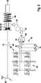
Die in
Die Weckvorrichtung
Vorteilhaftverweise ist die mindestens eine Bremssystemkomponente mittels der Induktionsspannung oder des Wecksignals aus dem ersten Energieverbrauch-Modus mit einem ersten Energieverbrauch in den zweiten Energieverbrauch-Modus mit einem gegenüber dem ersten Energieverbrauch gesteigerten zweiten Energieverbrauch steuerbar. Insbesondere kann die mindestens eine Bremssystemkomponente mittels der Induktionsspannung oder des Wecksignals aus einem deaktivierten/schlafenden Modus als dem ersten Energieverbrauch-Modus in einen aktivierten/vollaktiven Modus als den zweiten Energieverbrauch-Modus steuerbar sein.Advantageously, the at least one brake system component is controllable by means of the induction voltage or the wake-up signal from the first energy consumption mode with a first energy consumption in the second energy consumption mode with a second energy consumption increased compared to the first energy consumption. In particular, the at least one brake system component may be controllable by the induction voltage or the wake-up signal from a deactivated / dormant mode as the first energy consumption mode to an activated / fully active mode as the second energy consumption mode.
Der Magnet
Für die Weckvorrichtung
Beispielsweise kann der Magnet
Die Fahrerbremskraftübertragungskomponente
Der mindestens eine elektrische Leiter
Die in
Mittels der Induktionsspannung oder des Wecksignals können beispielsweise die Bremskraftverstärkervorrichtung
In der Ausführungsform der
Es wird darauf hingewiesen, dass die oben schon beschriebenen Vorteile auch bei der Ausbildungsform der
Ein elastischer Anschlag
Bei der in
Der Magnet
Der Magnet
Die vorteilhafte Weckvorrichtung
Der Rotor-Lagesensor
In einem Verfahrensschritt S1 wird ein an einer verstellbaren Fahrerbremskraftübertragungskomponente eines Bremssystems des Fahrzeugs mitverstellbar angeordneter Magnet bereitgestellt. Das Bereitstellen des Magneten erfolgt so, dass der benutzte Magnet mittels einer Getriebeeinrichtung derart an der (vorzugsweise linear) verstellbaren Fahrerbremskraftübertragungskomponente mitverstellbar angeordnet ist, dass der Magnet durch das Mitverstellen in eine Rotationsbewegung versetzt wird.In a method step S1, a magnet arranged in an adjustable manner on an adjustable driver brake power transmission component of a brake system of the vehicle is provided. The provision of the magnet is carried out so that the magnet used by means of a transmission device on the (preferably linear) adjustable driver brake power transmission component is arranged to be adjustable, that the magnet is offset by the Mitverstellen in a rotational movement.
In einem gleichzeitig, zuvor oder nachfolgend ausführbaren Verfahrensschritt S2 wird mindestens ein elektrischer Leiter bereitgestellt. Das Bereitstellen des elektrischen Leiters erfolgt so, dass bei einer durch das Mitverstellen des an der Fahrerbremskraftübertragungskomponente angeordneten Magneten bewirkten Relativbewegung zwischen dem Magneten und dem elektrischen Leiter eine Induktionsspannung in dem mindestens einen elektrischen Leiter induziert wird.At least one electrical conductor is provided in a simultaneously, previously or subsequently executable method step S2. The electrical conductor is provided in such a way that, in the case of a relative movement between the magnet and the electrical conductor caused by the co-displacement of the magnet arranged on the driver brake force transmission component, an induction voltage is induced in the at least one electrical conductor.
Des Weiteren wird in einem Verfahrensschritt S3 die induzierte Induktionsspannung oder ein unter Berücksichtigung der Induktionsspannung erzeugtes Wecksignal so an die mindestens eines Bremssystemkomponente des Bremssystems ausgegeben, dass die mindestens eine Bremssystemkomponente mittels der Induktionsspannung oder des Wecksignals aus einem ersten Energieverbrauch-Modus in einen von dem ersten Energieverbrauch-Modus abweichenden zweiten Energieverbrauch-Modus gesteuert wird. Beispielsweise kann der Induktionsstrom oder das Wecksignal an einen Prozessor oder einen Schaltkreis der mindestens einen Bremssystemkomponente bereitgestellt werden. Zum Erzeugen des Wecksignals kann auch die Induktionsspannung in das Wecksignal umgewandelt werden.Furthermore, in a method step S3, the induced induction voltage or a wake-up signal generated taking into account the induction voltage is output to the at least one brake system component of the brake system such that the at least one brake system component changes from a first energy consumption mode to one of the first one by means of the induction voltage or wake-up signal Energy consumption mode is controlled deviating second energy consumption mode. For example, the induction current or the wake-up signal may be provided to a processor or circuit of the at least one brake system component. For generating the wake-up signal, the induction voltage can also be converted into the wake-up signal.
Das oben beschriebene vorteilhafte Verfahren ermöglicht die Verwendung eines Magneten eines Elektromotors oder eines Sensors für die Weckvorrichtung. Beispielsweise kann als Magnet ein Permanentmagnet eines Elektromotors einer Bremskraftverstärkervorrichtung und/oder ein Permanentmagnet eines Rotor-Lagesensors der Bremskraftverstärkervorrichtung verwendet werden. The advantageous method described above allows the use of a magnet of an electric motor or a sensor for the alarm. For example, as the magnet, a permanent magnet of an electric motor of a brake booster device and / or a permanent magnet of a rotor position sensor of the brake booster device may be used.
ZITATE ENTHALTEN IN DER BESCHREIBUNG QUOTES INCLUDE IN THE DESCRIPTION
Diese Liste der vom Anmelder aufgeführten Dokumente wurde automatisiert erzeugt und ist ausschließlich zur besseren Information des Lesers aufgenommen. Die Liste ist nicht Bestandteil der deutschen Patent- bzw. Gebrauchsmusteranmeldung. Das DPMA übernimmt keinerlei Haftung für etwaige Fehler oder Auslassungen.This list of the documents listed by the applicant has been generated automatically and is included solely for the better information of the reader. The list is not part of the German patent or utility model application. The DPMA assumes no liability for any errors or omissions.
Zitierte PatentliteraturCited patent literature
- DE 10123730 A1 [0002] DE 10123730 A1 [0002]
Claims (13)
Priority Applications (9)
| Application Number | Priority Date | Filing Date | Title |
|---|---|---|---|
| DE102011088350A DE102011088350A1 (en) | 2011-12-13 | 2011-12-13 | Awakening device for a brake system component of a vehicle and method for waking up at least one brake system component of a vehicle |
| US14/354,309 US10286890B2 (en) | 2011-12-13 | 2012-10-15 | Wake-up device for a brake system component of a vehicle and method for exciting at least one brake system component of a vehicle |
| JP2014545143A JP5816379B2 (en) | 2011-12-13 | 2012-10-15 | Wake-up device for vehicle brake system components and method for wake-up of at least one brake system component of a vehicle |
| PCT/EP2012/070360 WO2013087252A1 (en) | 2011-12-13 | 2012-10-15 | Excitation device for a brake system component of a vehicle and method for exciting at least one brake system component of a vehicle |
| EP12775004.0A EP2790985B1 (en) | 2011-12-13 | 2012-10-15 | Excitation device for a brake system component of a vehicle and method for exciting at least one brake system component of a vehicle |
| IN3171DEN2014 IN2014DN03171A (en) | 2011-12-13 | 2012-10-15 | |
| KR1020147016058A KR101960997B1 (en) | 2011-12-13 | 2012-10-15 | Excitation device for a brake sysyem component of a vehicle and method for exciting at least one brake system component of a vehicle |
| CN201280061287.8A CN103987598B (en) | 2011-12-13 | 2012-10-15 | Excitation device for brake system component of vehicle and method for exciting at least one brake system component of vehicle |
| PL12775004T PL2790985T3 (en) | 2011-12-13 | 2012-10-15 | Excitation device for a brake system component of a vehicle and method for exciting at least one brake system component of a vehicle |
Applications Claiming Priority (1)
| Application Number | Priority Date | Filing Date | Title |
|---|---|---|---|
| DE102011088350A DE102011088350A1 (en) | 2011-12-13 | 2011-12-13 | Awakening device for a brake system component of a vehicle and method for waking up at least one brake system component of a vehicle |
Publications (1)
| Publication Number | Publication Date |
|---|---|
| DE102011088350A1 true DE102011088350A1 (en) | 2013-06-13 |
Family
ID=47045019
Family Applications (1)
| Application Number | Title | Priority Date | Filing Date |
|---|---|---|---|
| DE102011088350A Withdrawn DE102011088350A1 (en) | 2011-12-13 | 2011-12-13 | Awakening device for a brake system component of a vehicle and method for waking up at least one brake system component of a vehicle |
Country Status (9)
| Country | Link |
|---|---|
| US (1) | US10286890B2 (en) |
| EP (1) | EP2790985B1 (en) |
| JP (1) | JP5816379B2 (en) |
| KR (1) | KR101960997B1 (en) |
| CN (1) | CN103987598B (en) |
| DE (1) | DE102011088350A1 (en) |
| IN (1) | IN2014DN03171A (en) |
| PL (1) | PL2790985T3 (en) |
| WO (1) | WO2013087252A1 (en) |
Cited By (1)
| Publication number | Priority date | Publication date | Assignee | Title |
|---|---|---|---|---|
| DE102020213414A1 (en) | 2020-10-23 | 2022-04-28 | Continental Teves Ag & Co. Ohg | Procedure for waking up a braking system |
Families Citing this family (7)
| Publication number | Priority date | Publication date | Assignee | Title |
|---|---|---|---|---|
| US9511994B2 (en) | 2012-11-28 | 2016-12-06 | Invensense, Inc. | Aluminum nitride (AlN) devices with infrared absorption structural layer |
| US9618405B2 (en) * | 2014-08-06 | 2017-04-11 | Invensense, Inc. | Piezoelectric acoustic resonator based sensor |
| US10497747B2 (en) | 2012-11-28 | 2019-12-03 | Invensense, Inc. | Integrated piezoelectric microelectromechanical ultrasound transducer (PMUT) on integrated circuit (IC) for fingerprint sensing |
| US9114977B2 (en) | 2012-11-28 | 2015-08-25 | Invensense, Inc. | MEMS device and process for RF and low resistance applications |
| US10726231B2 (en) | 2012-11-28 | 2020-07-28 | Invensense, Inc. | Integrated piezoelectric microelectromechanical ultrasound transducer (PMUT) on integrated circuit (IC) for fingerprint sensing |
| DE102014220646A1 (en) * | 2014-10-13 | 2016-04-14 | Bayerische Motoren Werke Aktiengesellschaft | Use of a bus line for transmitting alternative signal codes |
| US10611356B2 (en) * | 2018-03-30 | 2020-04-07 | Veoneer Us, Inc. | System and method for transient wake up of processor controlling a motor of a brake booster subsystem |
Citations (1)
| Publication number | Priority date | Publication date | Assignee | Title |
|---|---|---|---|---|
| DE10123730A1 (en) | 2000-07-28 | 2002-03-14 | Continental Teves Ag & Co Ohg | System for reliably transmitting control element position transmits position signal over several signal channels, at least one with lower positional resolution |
Family Cites Families (17)
| Publication number | Priority date | Publication date | Assignee | Title |
|---|---|---|---|---|
| KR0130144B1 (en) * | 1995-08-14 | 1998-04-08 | 전성원 | The braking power boosting device |
| EP1307367B1 (en) * | 2000-07-28 | 2013-09-11 | Continental Teves AG & Co. oHG | System, position transmitter and a receiving device for reliably transmitting the position of a control element, and the use thereof |
| JP2004153924A (en) * | 2002-10-30 | 2004-05-27 | Hitachi Ltd | Permanent magnet rotating machine |
| MXPA05010405A (en) * | 2003-04-07 | 2005-11-23 | Continental Teves Ag & Co Ohg | Device for monitoring the position and displacement of a brake pedal. |
| US6991302B2 (en) * | 2003-09-26 | 2006-01-31 | Haldex Brake Products Ab | Brake system with distributed electronic control units |
| KR20070022316A (en) * | 2004-05-18 | 2007-02-26 | 지멘스 악티엔게젤샤프트 | Parking brake system equipped with a sensor |
| DE502005007513D1 (en) * | 2004-05-18 | 2009-07-30 | Continental Automotive Gmbh | PARKING BRAKE SYSTEM WITH SENSOR |
| FR2878215B1 (en) * | 2004-11-25 | 2007-01-05 | Renault Sas | ELECTRIC BRAKE DEVICE FOR VEHICLE |
| CN200948788Y (en) * | 2006-07-06 | 2007-09-19 | 桂林思超汽车科技有限公司 | Automobile tyre safety monitoring apparatus |
| DE102006052029B4 (en) | 2006-09-22 | 2020-01-09 | Osram Oled Gmbh | Light emitting device |
| US7880424B2 (en) * | 2006-09-28 | 2011-02-01 | Denso Corporation | Rotary electric apparatus having rotor with field winding inducing current therethrough for generating magnetic field |
| JP2008095909A (en) * | 2006-10-16 | 2008-04-24 | Hitachi Ltd | Electrically driven brake device |
| US8204661B2 (en) * | 2006-12-21 | 2012-06-19 | The Boeing Company | Reduced power mode for an aircraft electric brake system |
| EP2037221B1 (en) | 2007-09-13 | 2019-04-03 | Marquardt GmbH | Ignition lock for a motor vehicle |
| DE102008064049A1 (en) * | 2008-07-10 | 2010-01-14 | Continental Teves Ag & Co. Ohg | Automotive brake actuation assembly with wake-up sensor element |
| JP5216661B2 (en) * | 2009-03-31 | 2013-06-19 | 日立オートモティブシステムズ株式会社 | Control device for vehicle |
| JP5055336B2 (en) * | 2009-09-30 | 2012-10-24 | 日立オートモティブシステムズ株式会社 | Brake control device |
-
2011
- 2011-12-13 DE DE102011088350A patent/DE102011088350A1/en not_active Withdrawn
-
2012
- 2012-10-15 CN CN201280061287.8A patent/CN103987598B/en active Active
- 2012-10-15 US US14/354,309 patent/US10286890B2/en active Active
- 2012-10-15 JP JP2014545143A patent/JP5816379B2/en active Active
- 2012-10-15 EP EP12775004.0A patent/EP2790985B1/en active Active
- 2012-10-15 PL PL12775004T patent/PL2790985T3/en unknown
- 2012-10-15 WO PCT/EP2012/070360 patent/WO2013087252A1/en active Application Filing
- 2012-10-15 IN IN3171DEN2014 patent/IN2014DN03171A/en unknown
- 2012-10-15 KR KR1020147016058A patent/KR101960997B1/en active IP Right Grant
Patent Citations (1)
| Publication number | Priority date | Publication date | Assignee | Title |
|---|---|---|---|---|
| DE10123730A1 (en) | 2000-07-28 | 2002-03-14 | Continental Teves Ag & Co Ohg | System for reliably transmitting control element position transmits position signal over several signal channels, at least one with lower positional resolution |
Cited By (1)
| Publication number | Priority date | Publication date | Assignee | Title |
|---|---|---|---|---|
| DE102020213414A1 (en) | 2020-10-23 | 2022-04-28 | Continental Teves Ag & Co. Ohg | Procedure for waking up a braking system |
Also Published As
| Publication number | Publication date |
|---|---|
| US10286890B2 (en) | 2019-05-14 |
| JP2015501755A (en) | 2015-01-19 |
| KR101960997B1 (en) | 2019-03-21 |
| CN103987598A (en) | 2014-08-13 |
| KR20140101368A (en) | 2014-08-19 |
| WO2013087252A1 (en) | 2013-06-20 |
| EP2790985A1 (en) | 2014-10-22 |
| EP2790985B1 (en) | 2016-02-03 |
| IN2014DN03171A (en) | 2015-05-22 |
| JP5816379B2 (en) | 2015-11-18 |
| CN103987598B (en) | 2017-01-18 |
| US20150035375A1 (en) | 2015-02-05 |
| PL2790985T3 (en) | 2016-06-30 |
Similar Documents
| Publication | Publication Date | Title |
|---|---|---|
| EP2790985B1 (en) | Excitation device for a brake system component of a vehicle and method for exciting at least one brake system component of a vehicle | |
| DE102006006841B4 (en) | Control of the restart of an internal combustion engine | |
| EP2795131B1 (en) | Method for the start-up control of an electric vacuum pump | |
| DE102005004326A1 (en) | Starting device for an internal combustion engine with separate engagement and starting process | |
| WO2005113306A1 (en) | Parking brake system equipped with a sensor | |
| DE102006055766A1 (en) | Vehicle braking method for operating a combined motor vehicle brake installation uses a hydraulic and electro-mechanical braking system | |
| DE102011056688A1 (en) | Motor vehicle e.g. hybrid vehicle, has signal generating unit that generates acoustic signal for clearly defining engine operation and recuperation operation of electric motor in response to operating state of electric motor | |
| DE102008061821A1 (en) | Method for recuperation of energy in motor vehicle during recuperationable operating condition of motor vehicle, involves converting free energy into electrical or thermal energy | |
| DE102016210369A1 (en) | Electromechanical brake booster | |
| DE102008055898A1 (en) | Brake light controlling method for e.g. electric vehicle, involves activating brake light when torque supplied by machine exceeds preset threshold, and deactivating activated brake light when torque falls below another preset threshold | |
| DE102016201664A1 (en) | Electronic control unit for controlling the auto hold function | |
| DE102014210550A1 (en) | Sensor device for a brake system equipped with an electromechanical brake booster and method for determining a braking request specification to a brake system equipped with an electromechanical brake booster | |
| DE102019121759A1 (en) | BRAKE DEVICE AND METHOD FOR A VEHICLE | |
| DE102012018743B4 (en) | Method for operating an operating device for a motor vehicle and operating device | |
| DE102015016152A1 (en) | Haptic feedback at a user interface | |
| DE102015201032A1 (en) | Steering system for automated driving of a motor vehicle | |
| DE102010062238A1 (en) | Starting device, interface device and method for operating a system of a starting device | |
| DE102015015697A1 (en) | Method for controlling an electric machine for driving a motor vehicle and motor vehicle | |
| DE102009046231A1 (en) | Electric Brake System, particularly electro-mechanical brake system for motor vehicle, has brake circuit, and control unit for implementation of driver braking demand | |
| DE102011088301A1 (en) | Haptic accelerator pedal with DC motor operated actuator and method for controlling a haptic accelerator pedal | |
| DE102009029541A1 (en) | Method for operating a number of control units | |
| DE102013221479A1 (en) | A method for controlling a clutch start after an engine stop sailing phase of a motor vehicle | |
| DE102010044402A1 (en) | Start or stop device for motor vehicle, has electrically operated clutch, clutch pedal sensor, which is designed for generating corresponding clutch pedal position by actuation of clutch pedal, and control device | |
| DE102020206565A1 (en) | Control device and method for operating an energy storage module of a motorized braking device of a vehicle | |
| DE102011086408A1 (en) | Method for actuating electric circuit in circuit of windscreen wiper drive of windscreen wiper system, involves parking wiper in predetermined parking position, and opening electric circuit after wiper is parked |
Legal Events
| Date | Code | Title | Description |
|---|---|---|---|
| R005 | Application deemed withdrawn due to failure to request examination |