DE102011079139A1 - Sorting and conveying device for use in pharmaceutical industry for e.g. sorting closure stopper for closing/locking container, has discharge gutter arranged at outer circumference of pot and passed along circumference in specific angle - Google Patents
Sorting and conveying device for use in pharmaceutical industry for e.g. sorting closure stopper for closing/locking container, has discharge gutter arranged at outer circumference of pot and passed along circumference in specific angle Download PDFInfo
- Publication number
- DE102011079139A1 DE102011079139A1 DE201110079139 DE102011079139A DE102011079139A1 DE 102011079139 A1 DE102011079139 A1 DE 102011079139A1 DE 201110079139 DE201110079139 DE 201110079139 DE 102011079139 A DE102011079139 A DE 102011079139A DE 102011079139 A1 DE102011079139 A1 DE 102011079139A1
- Authority
- DE
- Germany
- Prior art keywords
- sorting
- pot
- sorting pot
- outlet channel
- conveying device
- Prior art date
- Legal status (The legal status is an assumption and is not a legal conclusion. Google has not performed a legal analysis and makes no representation as to the accuracy of the status listed.)
- Pending
Links
Images

Classifications
-
- B—PERFORMING OPERATIONS; TRANSPORTING
- B65—CONVEYING; PACKING; STORING; HANDLING THIN OR FILAMENTARY MATERIAL
- B65G—TRANSPORT OR STORAGE DEVICES, e.g. CONVEYORS FOR LOADING OR TIPPING, SHOP CONVEYOR SYSTEMS OR PNEUMATIC TUBE CONVEYORS
- B65G47/00—Article or material-handling devices associated with conveyors; Methods employing such devices
- B65G47/02—Devices for feeding articles or materials to conveyors
- B65G47/04—Devices for feeding articles or materials to conveyors for feeding articles
- B65G47/12—Devices for feeding articles or materials to conveyors for feeding articles from disorderly-arranged article piles or from loose assemblages of articles
- B65G47/14—Devices for feeding articles or materials to conveyors for feeding articles from disorderly-arranged article piles or from loose assemblages of articles arranging or orientating the articles by mechanical or pneumatic means during feeding
- B65G47/1407—Devices for feeding articles or materials to conveyors for feeding articles from disorderly-arranged article piles or from loose assemblages of articles arranging or orientating the articles by mechanical or pneumatic means during feeding the articles being fed from a container, e.g. a bowl
- B65G47/1414—Devices for feeding articles or materials to conveyors for feeding articles from disorderly-arranged article piles or from loose assemblages of articles arranging or orientating the articles by mechanical or pneumatic means during feeding the articles being fed from a container, e.g. a bowl by means of movement of at least the whole wall of the container
- B65G47/1421—Vibratory movement
Landscapes
- Engineering & Computer Science (AREA)
- Mechanical Engineering (AREA)
- Sealing Of Jars (AREA)
- Discharge Of Articles From Conveyors (AREA)
- Feeding Of Articles To Conveyors (AREA)
Abstract
Description
Stand der TechnikState of the art
Die vorliegende Erfindung betrifft eine Sortier- und Fördervorrichtung, um bevorratete Elemente auszurichten, zu sortieren und abzuführen, wobei die Vorrichtung einen verbesserten Auslauf aufweist.The present invention relates to a sorting and conveying apparatus for aligning, sorting and discharging stored items, the apparatus having an improved spout.
Derartige Sortier- und Fördervorrichtungen (z. B.
Offenbarung der ErfindungDisclosure of the invention
Die erfindungsgemäße Sortier- und Fördervorrichtung mit den Merkmalen des Anspruchs 1 weist demgegenüber den Vorteil auf, dass ein Nachfüllen eines Sortiertopfs deutlich vereinfacht ist. Insbesondere sind keine aufwendigen und teueren Hilfsmittel, wie z. B. Hubsäulen o. Ä. notwendig. Weiterhin kann erfindungsgemäß auch ein gesamter Ablauf deutlich vereinfacht werden. Dies wird erfindungsgemäß dadurch erreicht, dass die Sortier- und Fördereinrichtung einen Sortiertopf, einen Vorratsspeicher, sowie eine Auslaufrinne umfasst. Die Auslaufrinne ist dabei an einem äußeren Umfang des Sortiertopfes, ausgehend von einer oberen Öffnung des Sortiertopfes angeordnet. Die Auslaufrinne verläuft dabei entlang des äußeren Umfangs des Sortiertopfs über mehr als 360°. Somit wird erfindungsgemäß die gesamte Höhe des Sortiertopfes zum Aufbau einer Staukraft auf die bevorrateten Elemente in der Auslaufrinne verwendet. Dadurch, dass die Auslaufrinne über mehr als 360° angeordnet ist, können entsprechend viele Elemente in der Auslaufrinne angeordnet werden und die Auslaufrinne in schraubenzylindrischer Form vorgesehen werden, um die Elemente einer nachfolgenden Einrichtung zuzuführen. Weiterhin können die zu sortierenden Elemente in einer normalen Arbeitshöhe in den Sortiertopf eingefüllt werden, wobei der Aufbau der Vorrichtung trotzdem einfach und kostengünstig ausführbar ist.The sorting and conveying device according to the invention with the features of claim 1 has the advantage over that refilling a sorting pot is much easier. In particular, no complex and expensive tools, such. B. lifting columns o. Ä. necessary. Furthermore, according to the invention, an entire process can be significantly simplified. This is inventively achieved in that the sorting and conveying device comprises a sorting pot, a storage reservoir, and an outlet channel. The outlet channel is arranged on an outer circumference of the sorting pot, starting from an upper opening of the sorting pot. The outlet channel runs along the outer circumference of the sorting pot over more than 360 °. Thus, according to the invention, the entire height of the sorting pot is used to build up a jamming force on the stored items in the discharge chute. Because the outlet channel is arranged over more than 360 °, correspondingly many elements can be arranged in the outlet channel and the outlet channel can be provided in helical cylindrical form in order to feed the elements to a subsequent device. Furthermore, the items to be sorted can be filled in a normal working height in the sorting pot, the structure of the device is nevertheless simple and inexpensive executable.
Die Unteransprüche zeigen bevorzugte Weiterbildungen der Erfindung.The dependent claims show preferred developments of the invention.
Vorzugsweise ist im Sortiertopf eine Einlaufrinne angeordnet, welche die zu sortierenden Elemente aufnimmt und ausrichtet und welche direkt in die Auslaufrinne übergeht. Ein Übergang zwischen der Einlaufrinne und der Auslaufrinne ist dabei am oberen Rand des Sortiertopfes angeordnet.Preferably, an inlet chute is arranged in the sorting pot, which receives and aligns the elements to be sorted and which passes directly into the outlet chute. A transition between the inlet channel and the outlet channel is arranged at the top of the sorting pot.
Weiter bevorzugt weist die Auslaufrinne ein konstantes Gefälle auf. Hierdurch wird eine gleichmäßige Bewegung der zu sortierenden Elemente in der Auslaufrinne sichergestellt.More preferably, the outlet channel on a constant slope. This ensures a uniform movement of the items to be sorted in the outlet channel.
Besonders bevorzugt mündet die Auslaufrinne direkt in einer Abgabestation, wie z. B. einem Elementeschloss, an welchem die Elemente auf Behälter aufgesetzt werden und dann in einer nachgeordneten Verschließmaschine verschlossen werden. Durch die um mindestens 360° um den Sortiertopf verlaufende Auslaufrinne kann eine ausreichende Länge der Auslaufrinne sichergestellt werden, so dass es nicht mehr nötig ist, eine aufwendige Bahn, welche im Stand der Technik üblicherweise vor der nachgeordneten Einrichtung vorhanden ist, vorzusehen. Somit kann der Aufbau deutlich vereinfacht werden.Particularly preferably, the outlet channel opens directly into a dispensing station, such. B. an element lock on which the elements are placed on containers and then sealed in a downstream capping machine. By running through at least 360 ° to the sorting pot outlet channel sufficient length of the outlet channel can be ensured, so that it is no longer necessary to provide a complex path, which is usually present in the prior art before the downstream device. Thus, the structure can be significantly simplified.
Gemäß einer alternativen Ausgestaltung der Erfindung ist zwischen einer Abgabeposition und einem Ende der Auslaufrinne eine kurze Kappenbahn zwischengeschaltet, in welcher die ausgerichteten Elemente vollständig umschlossen sind, so dass auch Richtungswechsel der Förderrichtung möglich sind, ohne dass die Kappen herausfallen. Erfindungsgemäß kann die zwischengeschaltete Kappenbahn jedoch sehr kurz sein.According to an alternative embodiment of the invention, a short cap track is interposed between a dispensing position and an end of the outlet channel, in which the aligned elements are completely enclosed, so that direction changes of the conveying direction are possible without the caps fall out. However, according to the invention, the intermediate cap track can be very short.
Weiter bevorzugt ragt der über dem Sortiertopf angeordnete Vorratsspeicher in radialer Richtung etwas über einem Innenbereich des Sortiertopfes hinein. Hierdurch wird eine besonders einfache und sichere Zuführung der bevorrateten Elemente in den Sortiertopf erreicht.Further preferably, the storage reservoir arranged above the sorting pot protrudes in the radial direction slightly above an inner region of the Sorting pot into it. As a result, a particularly simple and secure supply of stored items is achieved in the sorting pot.
Besonders bevorzugt verläuft die Auslaufrinne über mehr als 540°. Weiter bevorzugt verläuft eine Einlaufrinne im Inneren des Sortiertopfes ebenfalls über mehr als 360°.Particularly preferably, the outlet channel extends over more than 540 °. More preferably, an inlet channel in the interior of the sorting pot also extends over more than 360 °.
Die erfindungsgemäße Sortier- und Fördervorrichtung wird bevorzugt in der pharmazeutischen Industrie zum Sortieren bzw. Ausrichten von Verschlusskappen o. Ä. verwendet, welche unmittelbar einer Kappenverschließstation zugeführt werden.The sorting and conveying device according to the invention is preferably used in the pharmaceutical industry for sorting or aligning caps or the like. used, which are fed directly to a cap closing station.
Zeichnungdrawing
Nachfolgend wird ein bevorzugtes Ausführungsbeispiel der Erfindung unter Bezugnahme auf die begleitende Zeichnung im Detail beschrieben. In der Zeichnung ist:Hereinafter, a preferred embodiment of the invention will be described in detail with reference to the accompanying drawings. In the drawing is:
Bevorzugte Ausführungsform der ErfindungPreferred embodiment of the invention
Nachfolgend wird unter Bezugnahme auf die
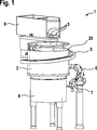
Wie insbesondere aus
Die Sortier- und Fördervorrichtung
Das Bezugszeichen
Die Auslaufrinne
Die Einlaufrinne
Durch die erfindungsgemäße Anordnung der Auslaufrinne
Der Vorratsspeicher
In
Die erfindungsgemäße Sortier- und Fördervorrichtung
ZITATE ENTHALTEN IN DER BESCHREIBUNG QUOTES INCLUDE IN THE DESCRIPTION
Diese Liste der vom Anmelder aufgeführten Dokumente wurde automatisiert erzeugt und ist ausschließlich zur besseren Information des Lesers aufgenommen. Die Liste ist nicht Bestandteil der deutschen Patent- bzw. Gebrauchsmusteranmeldung. Das DPMA übernimmt keinerlei Haftung für etwaige Fehler oder Auslassungen.This list of the documents listed by the applicant has been generated automatically and is included solely for the better information of the reader. The list is not part of the German patent or utility model application. The DPMA assumes no liability for any errors or omissions.
Zitierte PatentliteraturCited patent literature
- DE 10322477 A1 [0002] DE 10322477 A1 [0002]
Claims (8)
Priority Applications (3)
| Application Number | Priority Date | Filing Date | Title |
|---|---|---|---|
| DE201110079139 DE102011079139A1 (en) | 2010-08-05 | 2011-07-14 | Sorting and conveying device for use in pharmaceutical industry for e.g. sorting closure stopper for closing/locking container, has discharge gutter arranged at outer circumference of pot and passed along circumference in specific angle |
| ITMI20111477 ITMI20111477A1 (en) | 2010-08-05 | 2011-08-02 | SELECTION AND TRANSPORTATION DEVICE WITH IMPROVED EXIT |
| CN201110227417.8A CN102431775B (en) | 2010-08-05 | 2011-08-05 | There is sorting and the conveyer device of the outlet of improvement |
Applications Claiming Priority (3)
| Application Number | Priority Date | Filing Date | Title |
|---|---|---|---|
| DE102010038935.8 | 2010-08-05 | ||
| DE102010038935 | 2010-08-05 | ||
| DE201110079139 DE102011079139A1 (en) | 2010-08-05 | 2011-07-14 | Sorting and conveying device for use in pharmaceutical industry for e.g. sorting closure stopper for closing/locking container, has discharge gutter arranged at outer circumference of pot and passed along circumference in specific angle |
Publications (1)
| Publication Number | Publication Date |
|---|---|
| DE102011079139A1 true DE102011079139A1 (en) | 2012-04-19 |
Family
ID=45895953
Family Applications (1)
| Application Number | Title | Priority Date | Filing Date |
|---|---|---|---|
| DE201110079139 Pending DE102011079139A1 (en) | 2010-08-05 | 2011-07-14 | Sorting and conveying device for use in pharmaceutical industry for e.g. sorting closure stopper for closing/locking container, has discharge gutter arranged at outer circumference of pot and passed along circumference in specific angle |
Country Status (2)
| Country | Link |
|---|---|
| CN (1) | CN102431775B (en) |
| DE (1) | DE102011079139A1 (en) |
Cited By (1)
| Publication number | Priority date | Publication date | Assignee | Title |
|---|---|---|---|---|
| DE102016208306A1 (en) | 2016-05-13 | 2017-11-16 | Robert Bosch Gmbh | Sorting plant for closures and methods for producing pharmaceutical products |
Families Citing this family (3)
| Publication number | Priority date | Publication date | Assignee | Title |
|---|---|---|---|---|
| CN102826349A (en) * | 2012-09-18 | 2012-12-19 | 吴江市华恒精密五金有限公司 | Vibrating tray for stepped nuts |
| CN102826351A (en) * | 2012-09-18 | 2012-12-19 | 吴江市华恒精密五金有限公司 | Vibrating tray for pins |
| CN110668099B (en) * | 2019-09-27 | 2021-08-13 | 佛山市顺德区恒骏金属制品有限公司 | Spiral screw directional feeding device |
Citations (1)
| Publication number | Priority date | Publication date | Assignee | Title |
|---|---|---|---|---|
| DE10322477A1 (en) | 2003-05-19 | 2004-12-16 | Robert Bosch Gmbh | Sorting and conveying device |
Family Cites Families (8)
| Publication number | Priority date | Publication date | Assignee | Title |
|---|---|---|---|---|
| US3656605A (en) * | 1970-06-05 | 1972-04-18 | Larry C Gess | Apparatus for orienting and feeding caps |
| DD109846A1 (en) * | 1974-02-04 | 1974-11-20 | ||
| JPS5953308A (en) * | 1982-09-22 | 1984-03-28 | Hitachi Ltd | Conveyance device |
| DD284650A5 (en) * | 1989-06-05 | 1990-11-21 | Veb Industriewerke Karl-Marx-Stadt,Dd | FEEDING DEVICE FOR HEADLINK ROTATIONAL SYMMETRIC PARTS |
| RO107114B1 (en) * | 1989-12-06 | 1993-09-30 | Imre Miklos | Storing and dispensing installation for pellets |
| CN2186231Y (en) * | 1993-08-28 | 1994-12-28 | 郭清亮 | Shaking material detecter special for T-shape nail |
| US5713454A (en) * | 1995-06-14 | 1998-02-03 | Risdon Corporation | Method and apparatus for transferring nonoriented mascara applications |
| KR100752271B1 (en) * | 2006-08-29 | 2007-08-29 | 엠에스에이치 주식회사 | Nal-clip feeder |
-
2011
- 2011-07-14 DE DE201110079139 patent/DE102011079139A1/en active Pending
- 2011-08-05 CN CN201110227417.8A patent/CN102431775B/en active Active
Patent Citations (1)
| Publication number | Priority date | Publication date | Assignee | Title |
|---|---|---|---|---|
| DE10322477A1 (en) | 2003-05-19 | 2004-12-16 | Robert Bosch Gmbh | Sorting and conveying device |
Cited By (1)
| Publication number | Priority date | Publication date | Assignee | Title |
|---|---|---|---|---|
| DE102016208306A1 (en) | 2016-05-13 | 2017-11-16 | Robert Bosch Gmbh | Sorting plant for closures and methods for producing pharmaceutical products |
Also Published As
| Publication number | Publication date |
|---|---|
| CN102431775B (en) | 2016-09-28 |
| CN102431775A (en) | 2012-05-02 |
Similar Documents
| Publication | Publication Date | Title |
|---|---|---|
| DE3740823C2 (en) | Device for removing liquids from a container | |
| EP2444363B1 (en) | Method and device for capping containers with container closures | |
| DE102011079139A1 (en) | Sorting and conveying device for use in pharmaceutical industry for e.g. sorting closure stopper for closing/locking container, has discharge gutter arranged at outer circumference of pot and passed along circumference in specific angle | |
| EP2911949A1 (en) | Container and method for adding a mixture component | |
| EP3118139B1 (en) | System and capsule with a capsule body, preferably formed in a rotationally symmetrical manner | |
| EP2081860B1 (en) | Apparatus for orienting a container | |
| DE102016122041A1 (en) | Multicomponent container | |
| WO1997008068A1 (en) | Device for airing a liquids container | |
| DE102016009483B4 (en) | Container closure system | |
| DE19505805C2 (en) | Product receptacle for flowable and / or pourable products | |
| DE3046348A1 (en) | DEVICE FOR SUPPLYING THE INJECTION MOLDING UNIT OF A PLASTIC INJECTION MOLDING MACHINE | |
| DE102020131081B3 (en) | Method for emptying viscous material from a cartridge that is open on both sides, as well as a suitable emptying device | |
| DE2131805A1 (en) | Valve system | |
| DE102004017765B3 (en) | Sealing device for a two-component packaging comprises a connecting sleeve, an insert part, a securing device, a cylindrical casing, spokes, control ramps, a dispensing opening, threaded cams, and control cams | |
| EP1899258A1 (en) | Device for preventing filled vessels from spilling during conveying of the same | |
| DE1761544B1 (en) | FILLING DEVICE FOR VOLUMETRIC DOSING OF A POWDER RING OR GRAY SUBSTANCE IN A CONTAINER | |
| DE3901247C2 (en) | ||
| DE390776C (en) | Filler pencil | |
| DE102021124058B3 (en) | drilling | |
| EP4153527A1 (en) | Adapter for connecting a refill container | |
| DE102022102626A1 (en) | INFILLING DEVICE, SAMPLER CONNECTION DEVICE WITH SUCH INFILLING DEVICE AND RELATIVE PROCEDURE | |
| DE257857C (en) | ||
| DE927499C (en) | Filling device accommodating several vessels to be filled | |
| DE1093723B (en) | Closure piece for container | |
| EP3034422A1 (en) | Transportable fuel tank |
Legal Events
| Date | Code | Title | Description |
|---|---|---|---|
| R123 | Application deemed withdrawn due to non-payment of filing fee | ||
| R409 | Internal rectification of the legal status completed | ||
| R409 | Internal rectification of the legal status completed | ||
| R012 | Request for examination validly filed | ||
| R082 | Change of representative |
Representative=s name: DREISS PATENTANWAELTE PARTG MBB, DE |
|
| R081 | Change of applicant/patentee |
Owner name: SYNTEGON TECHNOLOGY GMBH, DE Free format text: FORMER OWNER: ROBERT BOSCH PACKAGING TECHNOLOGY GMBH, 71332 WAIBLINGEN, DE Owner name: SYNTEGON TECHNOLOGY GMBH, DE Free format text: FORMER OWNER: ROBERT BOSCH GMBH, 70469 STUTTGART, DE |
|
| R082 | Change of representative |
Representative=s name: DREISS PATENTANWAELTE PARTG MBB, DE |
|
| R016 | Response to examination communication |