DE102011075393B4 - Arrangement for the actuation of an element in a projection exposure apparatus - Google Patents
Arrangement for the actuation of an element in a projection exposure apparatus Download PDFInfo
- Publication number
- DE102011075393B4 DE102011075393B4 DE102011075393A DE102011075393A DE102011075393B4 DE 102011075393 B4 DE102011075393 B4 DE 102011075393B4 DE 102011075393 A DE102011075393 A DE 102011075393A DE 102011075393 A DE102011075393 A DE 102011075393A DE 102011075393 B4 DE102011075393 B4 DE 102011075393B4
- Authority
- DE
- Germany
- Prior art keywords
- actuator
- arrangement according
- filter
- forces
- actuator part
- Prior art date
- Legal status (The legal status is an assumption and is not a legal conclusion. Google has not performed a legal analysis and makes no representation as to the accuracy of the status listed.)
- Expired - Fee Related
Links
Images


Classifications
-
- G—PHYSICS
- G03—PHOTOGRAPHY; CINEMATOGRAPHY; ANALOGOUS TECHNIQUES USING WAVES OTHER THAN OPTICAL WAVES; ELECTROGRAPHY; HOLOGRAPHY
- G03F—PHOTOMECHANICAL PRODUCTION OF TEXTURED OR PATTERNED SURFACES, e.g. FOR PRINTING, FOR PROCESSING OF SEMICONDUCTOR DEVICES; MATERIALS THEREFOR; ORIGINALS THEREFOR; APPARATUS SPECIALLY ADAPTED THEREFOR
- G03F7/00—Photomechanical, e.g. photolithographic, production of textured or patterned surfaces, e.g. printing surfaces; Materials therefor, e.g. comprising photoresists; Apparatus specially adapted therefor
- G03F7/70—Microphotolithographic exposure; Apparatus therefor
- G03F7/70691—Handling of masks or workpieces
- G03F7/70766—Reaction force control means, e.g. countermass
-
- G—PHYSICS
- G03—PHOTOGRAPHY; CINEMATOGRAPHY; ANALOGOUS TECHNIQUES USING WAVES OTHER THAN OPTICAL WAVES; ELECTROGRAPHY; HOLOGRAPHY
- G03F—PHOTOMECHANICAL PRODUCTION OF TEXTURED OR PATTERNED SURFACES, e.g. FOR PRINTING, FOR PROCESSING OF SEMICONDUCTOR DEVICES; MATERIALS THEREFOR; ORIGINALS THEREFOR; APPARATUS SPECIALLY ADAPTED THEREFOR
- G03F7/00—Photomechanical, e.g. photolithographic, production of textured or patterned surfaces, e.g. printing surfaces; Materials therefor, e.g. comprising photoresists; Apparatus specially adapted therefor
- G03F7/70—Microphotolithographic exposure; Apparatus therefor
- G03F7/708—Construction of apparatus, e.g. environment aspects, hygiene aspects or materials
- G03F7/70808—Construction details, e.g. housing, load-lock, seals or windows for passing light in or out of apparatus
- G03F7/70825—Mounting of individual elements, e.g. mounts, holders or supports
Abstract
Anordnung zur Aktuierung eines Elementes (100, 200, 300) in einem optischen System einer Projektionsbelichtungsanlage, wobei die Projektionsbelichtungsanlage einen Tragrahmen (110, 210, 310) aufweist, mit • wenigstens einem Aktuator (101, 201, 301) zur Ausübung steuerbarer Kräfte auf das Element (100, 200, 300); • wobei der Aktuator (101, 201, 301) einen ersten Aktuatorteil (101a, 201a, 301a), welcher an den Tragrahmen (110, 210, 310) über wenigstens ein mechanisches Filter (140, 240, 340) gekoppelt ist, und einen zweiten Aktuatorteil (101b, 201b, 301b), welcher unmittelbar an den Tragrahmen (110, 210, 310) mechanisch gekoppelt ist, aufweist; und • wobei der erste Aktuatorteil (101a, 201a, 301a) durch den zweiten Aktuatorteil (101b, 201b, 301b) bei der Ausübung von Kräften auf das Element (100, 200, 300) wenigstens teilweise entlastet wird.Arrangement for actuating an element (100, 200, 300) in an optical system of a projection exposure apparatus, the projection exposure apparatus comprising a support frame (110, 210, 310) with • at least one actuator (101, 201, 301) for exercising controllable forces the element (100, 200, 300); Wherein the actuator (101, 201, 301) has a first actuator part (101a, 201a, 301a) which is coupled to the support frame (110, 210, 310) via at least one mechanical filter (140, 240, 340), and a second actuator part (101b, 201b, 301b) which is mechanically coupled directly to the support frame (110, 210, 310); and wherein the first actuator part (101a, 201a, 301a) is at least partially relieved by the second actuator part (101b, 201b, 301b) upon application of forces to the element (100, 200, 300).
Description
HINTERGRUND DER ERFINDUNGBACKGROUND OF THE INVENTION
Gebiet der ErfindungField of the invention
Die Erfindung betrifft eine Anordnung zur Aktuierung eines Elementes in einer Projektionsbelichtungsanlage.The invention relates to an arrangement for the actuation of an element in a projection exposure apparatus.
Stand der TechnikState of the art
Mikrolithographie wird zur Herstellung mikrostrukturierter Bauelemente, wie beispielsweise integrierter Schaltkreise oder LCD's, angewendet. Der Mikrolithographieprozess wird in einer sogenannten Projektionsbelichtungsanlage durchgeführt, welche eine Beleuchtungseinrichtung und ein Projektionsobjektiv aufweist. Das Bild einer mittels der Beleuchtungseinrichtung beleuchteten Maske (= Retikel) wird hierbei mittels des Projektionsobjektivs auf ein mit einer lichtempfindlichen Schicht (Photoresist) beschichtetes und in der Bildebene des Projektionsobjektivs angeordnetes Substrat (z. B. ein Siliziumwafer) projiziert, um die Maskenstruktur auf die lichtempfindliche Beschichtung des Substrats zu übertragen.Microlithography is used to fabricate microstructured devices such as integrated circuits or LCDs. The microlithography process is carried out in a so-called projection exposure apparatus which has an illumination device and a projection objective. In this case, the image of a mask (= reticle) illuminated by the illumination device is projected onto a substrate (eg a silicon wafer) coated with a photosensitive layer (photoresist) and arranged in the image plane of the projection objective to project the mask structure onto the mask transfer photosensitive coating of the substrate.
In einer für EUV (d. h. für elektromagnetische Strahlung mit einer Wellenlänge unterhalb von 15 nm) ausgelegten Projektionsbelichtungsanlage werden mangels Vorhandenseins lichtdurchlässiger Materialien Spiegel als optische Komponenten für den Abbildungsprozess verwendet. Diese Spiegel können auf einem Tragrahmen (auch als „Kraftaufnahmerahmen” oder „force frame” bezeichnet) befestigt und wenigstens teilweise manipulierbar ausgestaltet sein, um eine Bewegung des jeweiligen Spiegels beispielsweise in sechs Freiheitsgraden (d. h. hinsichtlich Verschiebungen in den drei Raumrichtungen x, y und z sowie hinsichtlich Rotationen Rx, Ry und Rz um entsprechende Achsen) zu ermöglichen, wodurch etwa im Betrieb der Projektionsbelichtungsanlage auftretende Änderungen der optischen Eigenschaften z. B. infolge von thermischen Einflüssen kompensiert werden können. Des Weiteren kann zusätzlich zum Tragrahmen ein von diesem mechanisch entkoppelter Sensorrahmen (= „sensor frame”) vorgesehen sein.In a projection exposure apparatus designed for EUV (ie for electromagnetic radiation with a wavelength below 15 nm), mirrors are used as optical components for the imaging process due to the lack of light-transmissive materials. These mirrors may be mounted on a support frame (also referred to as a "force frame") and at least partially manipulatable to provide movement of the respective mirror in, for example, six degrees of freedom (ie, displacements in the three spatial directions x, y, and z as well as with respect to rotations R x , R y and R z to allow corresponding axes), whereby occurring during operation of the projection exposure system changes in the optical properties z. B. can be compensated as a result of thermal effects. Furthermore, a sensor frame mechanically decoupled from this (= "sensor frame") may be provided in addition to the support frame.
Dabei kann die jeweilige Spiegelposition relativ zu diesem Sensorrahmen mittels eines Positionssensors gemessen und mittels eines Reglers über einen Aktuator auf den gewünschten Wert eingestellt werden. Hierbei tritt nun im Betrieb der Projektionsbelichtungsanlage grundsätzlich das Problem auf, dass jede von einem Aktuator auf ein Element wie z. B. den jeweiligen Spiegel ausgeübte Kraft aufgrund des Newtonschen Prinzips „actio = reactio” mit einer in entgegengesetzter Richtung wirkenden Reaktionskraft gleichen Betrages einhergeht. Ein Einwirken dieser Reaktionskraft auf den Sensorrahmen im Betrieb der Projektionsbelichtungsanlage hätte aber zur Folge, dass die am Sensorrahmen vorgesehenen Sensoren im Wesentlichen nur noch parasitäre Dynamik messen, und ist somit zu verhindern.In this case, the respective mirror position can be measured relative to this sensor frame by means of a position sensor and adjusted by means of a controller via an actuator to the desired value. In this case, the problem generally arises in the operation of the projection exposure apparatus that each of an actuator on an element such. B. force applied to the respective mirror due to the Newtonian principle "actio = reactio" with an acting in the opposite direction reaction force of the same amount goes. However, an action of this reaction force on the sensor frame during operation of the projection exposure apparatus would mean that the sensors provided on the sensor frame essentially only measure parasitic dynamics, and is therefore to be prevented.
Bekannte Ansätze zur Überwindung dieses Problems beinhalten den Einsatz eines mechanischen Filters in Form eines Feder-Masse-Systems auf dem Kraftpfad zwischen Spiegel und Sensorrahmen. Zum Stand der Technik wird beispielsweise auf
In
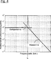
Bei mechanischen Filtern hängt die Unterdrückung der Aktuatorkräfte vom relativen Abstand der Anregungsfrequenz zur Filterfrequenz ab. Die Filterfrequenz fF ist hierbei gegeben ![]()
![]()
Eine exemplarische Übertragungsfunktion der Reaktionskraftunterdrückung (d. h. „Aktuatorkraft” zu „Kraft auf die Tragstruktur”) ist in
Dies hat z. B. für Aktuatoren, die relativ große statische Lasten tragen müssen, zur Folge, dass speziell bei niedrigen Filterfrequenzen (< 100 Hz) aufgrund der geringen Federsteifigkeiten große bis unpraktikable (> 1 cm) statische Auslenkungen auftreten können. Dem ließe sich zwar grundsätzlich durch Verwendung großer Reaktionsmassen entgegenwirken, was jedoch aufgrund von Bauraumbeschränkungen oft nicht realisierbar ist. Zur Unterdrückung der auftretenden Reaktionskräfte werden folglich vergleichsweise große Filtermassen benötigt, deren Integration in ein EUV-System von begrenztem verfügbarem Bauraum problematisch oder sogar unmöglich ist. Dies gilt in zunehmendem Maße für hochaperturige EUV-Systeme (beispielsweise EUV-Systeme mit einer numerischen Apertur NA größer als 0.3), bei denen in der Regel bereits die Anordnung der Spiegel selbst ohne Störung des optischen Strahlengangs eine anspruchsvolle Herausforderung darstellt.This has z. As for actuators that must carry relatively large static loads, with the result that especially at low filter frequencies (<100 Hz) due to the low spring stiffness large to impractical (> 1 cm) static deflections can occur. Although this could be counteracted in principle by using large reaction masses, but this is often not feasible due to space limitations. To suppress the reaction forces occurring therefore comparatively large filter masses are required whose integration into an EUV system of limited available space is problematic or even impossible. This is increasingly true for high-aperture EUV systems (for example, EUV systems with a numerical aperture NA greater than 0.3), where usually even the arrangement of the mirror itself without interference of the optical beam path presents a challenging challenge.
ZUSAMMENFASSUNG DER ERFINDUNGSUMMARY OF THE INVENTION
Aufgabe der vorliegenden Erfindung ist es, eine Anordnung zur Aktuierung eines Elementes in einer Projektionsbelichtungsanlage bereitzustellen, welche bei kompaktem Aufbau eine möglichst störungsfreie Aktuierung des Elementes ermöglicht.Object of the present invention is to provide an arrangement for the actuation of an element in a projection exposure system, which allows a compact construction as trouble-free as possible actuation of the element.
Diese Aufgabe wird durch die Anordnung gemäß den Merkmalen des unabhängigen Anspruchs 1 gelöst.This object is achieved by the arrangement according to the features of the
Eine Anordnung zur Aktuierung eines Elementes in einem optischen System einer Projektionsbelichtungsanlage, wobei die Projektionsbelichtungsanlage einen Tragrahmen aufweist, umfasst:
- – wenigstens einen Aktuator zur Ausübung steuerbarer Kräfte auf das Element;
- – wobei der Aktuator einen ersten Aktuatorteil, welcher an den Tragrahmen über wenigstens ein mechanisches Filter gekoppelt ist, und einen zweiten Aktuatorteil, welcher unmittelbar an den Tragrahmen mechanisch gekoppelt ist, aufweist; und
- – wobei der erste Aktuatorteil durch den zweiten Aktuatorteil bei der Ausübung von Kräften auf das Element wenigstens teilweise entlastet wird.
- At least one actuator for applying controllable forces to the element;
- - wherein the actuator has a first actuator part, which is coupled to the support frame via at least one mechanical filter, and a second actuator part, which is mechanically coupled directly to the support frame has; and
- - Wherein the first actuator part is at least partially relieved by the second actuator part in the exertion of forces on the element.
Gemäß einer Ausführungsform weist das mechanische Filter eine Filterfrequenz auf, wobei die Anordnung derart ausgelegt ist, dass vom Aktuator auf das Element ausgeübte Kräfte mit einer Frequenz unterhalb der Filterfrequenz zumindest überwiegend von dem zweiten Aktuatorteil auf das Element ausgeübt werden.According to one embodiment, the mechanical filter has a filter frequency, wherein the arrangement is designed such that forces exerted by the actuator on the element with a frequency below the filter frequency at least predominantly exerted by the second actuator part on the element.
Der Erfindung geht von der Erkenntnis aus, dass grundsätzlich nur die mit den vergleichsweise hochfrequenten Kräften des Aktuators einhergehenden Reaktionskräfte von störendem Einfluss auf den Tragrahmen bzw. die Dynamik des Gesamtsystems sind. Zwar sind die hochfrequenten Kräfte des Aktuators bzw. die damit einhergehenden Reaktionskräfte an sich relativ klein, die besagten Reaktionskräfte können jedoch Eigenschwingungsmoden im Tragrahmen anregen. Die Gefahr besteht darin, dass die angeregten Schwingungsmodi über Sensor und Regler auf den Aktor rückkoppeln und damit Stabilitätsprobleme im Regelkreis verursachen bzw. seine Regelgüte einschränken. Infolgedessen müssen Reaktionskräfte im höheren Frequenzbereich unterdrückt werden bzw. deren Durchschlagen auf den Tragrahmen muss verhindert werden. Hingegen sind die vergleichsweise niederfrequenten Kräfte bzw. die damit einhergehenden Reaktionskräfte aufgrund des Umstandes, dass in dem betreffenden niederen Frequenzbereich keine Eigenschwingungsmoden im Tragrahmen auftreten, für die Stabilität und Regelgüte des Regelkreises nicht weiter störend, weshalb diese niederfrequenten Kräfte zum Tragrahmen „durchgelassen” werden dürfen.The invention is based on the recognition that, in principle, only the reaction forces associated with the comparatively high-frequency forces of the actuator are of disturbing influence on the supporting frame or the dynamics of the overall system. Although the high-frequency forces of the actuator or the associated reaction forces are relatively small in itself, the said reaction forces can stimulate natural vibration modes in the support frame. The danger is that the excited oscillation modes are coupled back to the actuator via the sensor and controller and thus cause stability problems in the control loop or limit its control quality. As a result, reaction forces in the higher frequency range must be suppressed or their penetration on the support frame must be prevented. By contrast, the comparatively low-frequency forces or the associated reaction forces due to the fact that in the respective lower frequency range no natural modes occur in the support frame, not disturbing for the stability and control performance of the control loop, which is why these low-frequency forces to the support frame "allowed to pass" ,
Von dieser Erkenntnis ausgehend liegt der Erfindung das Konzept zugrunde, den Aktuator in einen für die Erzeugung hochfrequenter Kräfte „zuständigen” ersten Aktuatorteil und einen für die Erzeugung niederfrequenter Kräfte „zuständigen” zweiten Aktuatorteil aufzuteilen, wobei die den vom ersten Aktuatorteil erzeugten hochfrequenten Kräften entsprechenden (infolge des „actio = reactio”-Prinzips entstehenden) Reaktionskräfte auf eine Reaktionsmasse bzw. Filtermasse eines mechanischen Filters gegeben werden, wohingegen der die niederfrequenten Kräfte erzeugende zweite Aktuatorteil mechanisch direkt (d. h. ohne zusätzliche Reaktionsmasse bzw. ohne Zwischenschaltung eines mechanischen Filters) gegen den Tragrahmen abgestützt wird.Based on this knowledge, the invention is based on the concept of dividing the actuator into a "responsible" first actuator part and a "responsible" for generating low-frequency forces "second actuator part responsible for the generation of low-frequency forces, the corresponding corresponding to the high-frequency forces generated by the first actuator ( As a result of the "actio = reactio" principle resulting reaction forces on a reaction mass or filter mass of a mechanical filter are given, whereas the low-frequency forces generating second actuator part mechanically directly (ie without additional reaction mass or without the interposition of a mechanical filter) against the support frame is supported.
Mit anderen Worten wird erfindungsgemäß ein frequenzmäßig effektiv „aufgesplitteter” Aktuator zwischen Element und Tragstruktur eingesetzt, wobei die mit den hochfrequenten Kräften des Aktuators bzw. dessen ersten Aktuatorteils einhergehenden Reaktionskräfte mechanisch gefiltert, die übrigen (niederfrequenten) Kräfte des Aktuators bzw. dessen zweiten Aktuatorteils jedoch ungefiltert an den Tragrahmen durchgelassen werden. Diese „Aufsplittung” des Aktuators kann, wie im Weiteren noch näher erläutert wird, in solcher Weise erfolgen, dass eine vom Aktuator insgesamt auf das Element auszuübende (Korrektur-)Kraft zunächst auf den ersten Aktuatorteil gegeben wird und sodann die konstanten bzw. niederfrequenten Kräfte nach und nach, etwa wie noch beschrieben unter Einsatz einer Integriereinheit, auf den zur Entlastung bestimmten zweiten Aktuatorteil „hinübergezogen” werden. Somit beinhaltet die Erfindung nicht notwendigerweise von vorneherein bei der Ansteuerung des Aktuators eine Frequenzaufteilung in unterschiedliche Frequenzbereiche (wie diese etwa bei einem aus Hoch- und Tieftöner aufgebauten Lautsprecher erfolgt), sondern kann auch durch eine effektive Aufsplittung des Aktuators durch Realisierung eines geeigneten Signalflusses verwirklicht werden. Alternativ kann diese Aufspaltung über ein Netzwerk oder über ein analoges oder digitales Filter erfolgen, welches das Kraftsignal derart in zwei Komponenten zerlegt, dass deren Summe gleich dem Eingangssignal ist und die eine Komponente die statischen und niederfrequenten Anteile beinhaltet und die andere Komponente die hochfrequenten Anteile beinhaltet. In other words, according to the invention, a frequency-effectively "split-up" actuator is used between the element and the supporting structure, the reaction forces associated with the high-frequency forces of the actuator or its first actuator part being mechanically filtered, the remaining (low-frequency) forces of the actuator or its second actuator part, however be passed unfiltered to the support frame. This "splitting" of the actuator can, as will be explained in more detail below, take place in such a way that a (correction) force to be exerted by the actuator on the element is first given to the first actuator part and then the constant or low-frequency forces gradually, as described above using an integrating unit, are "pulled over" to the second actuator part intended for the relief. Thus, the invention does not necessarily include from the outset in the control of the actuator, a frequency division into different frequency ranges (as this takes place in a constructed from high and woofer loudspeaker), but can also be realized by an effective splitting of the actuator by implementing a suitable signal flow , Alternatively, this splitting can take place via a network or via an analog or digital filter which splits the force signal into two components such that their sum is equal to the input signal and one component contains the static and low-frequency components and the other component contains the high-frequency components ,
Die erfindungsgemäße (im vorstehenden Sinne „effektive”) Aufteilung des Aktuators in einen höherfrequenten und einen niederfrequenten Aktuatorteil und die hierdurch ermöglichte, separate bzw. unterschiedliche Behandlung der von diesen Aktuatorteilen ausgehenden Reaktionskräfte hat nun zur Folge, dass vergleichsweise große Konstantkräfte von dem direkt an den Tragrahmen mechanisch angebundenen zweiten Aktuatorteil erzeugt werden können und insoweit keine mechanische Filtermasse erforderlich ist, so dass die letztendlich nur noch für die Reaktionskräfte aufgrund der vom ersten Aktuatorteil erzeugten Kräfte benötigte Filtermasse wesentlich kleiner und damit der Aktuator insgesamt wesentlich kompakter ausgelegt sein kann.The inventive (in the above sense "effective") division of the actuator into a high-frequency and a low-frequency actuator part and thus made possible, separate or different treatment of the reaction forces emanating from these Aktuatorteilen now has the consequence that comparatively large constant forces of the directly to the Support frame mechanically connected second actuator part can be generated and insofar no mechanical filter mass is required, so that the ultimately required only for the reaction forces due to the forces generated by the first actuator part filter mass much smaller and thus the actuator can be designed much more compact overall.
Ferner können alle Kräfte, die durch eine Steuerung aufgebracht werden, über den Aktor ohne Reaktionsmasse übertragen und dadurch die durch die Kräfte hervorgerufenen Reaktionsmassenauslenkungen vermieden werden. Ein Beispiel sind die üblicherweise von einem Sollwertgenerator erzeugten Beschleunigungskräfte für eine Bewegung des Spiegels.Furthermore, all forces applied by a controller can be transmitted via the actuator without reaction mass, thereby avoiding the reaction mass deflections caused by the forces. An example is the acceleration forces normally generated by a setpoint generator for a movement of the mirror.
Mit anderen Worten kann die im erfindungsgemäßen Aufbau letztlich insgesamt erforderliche Filtermasse im Vergleich zu einer Anordnung, bei welcher der gesamte Aktuator an den Tragrahmen über ein mechanisches Filter mechanisch angekoppelt wird (d. h. im Vergleich zu einer mechanischen Filterung sämtlicher Reaktionskräfte) deutlich kleiner ausgestaltet sein, da sie über die erfindungsgemäße Aufteilung bzw. „Frequenzaufsplittung” des Aktuators von auftretenden Konstantkräften befreit ist.In other words, the total required in the structure of the invention ultimately filter mass compared to an arrangement in which the entire actuator is mechanically coupled to the support frame via a mechanical filter (ie compared to a mechanical filtering of all reaction forces) be designed much smaller, since it is freed of occurring constant forces via the division according to the invention or "frequency splitting" of the actuator.
Im Ergebnis wird es insbesondere möglich, den erfindungsgemäß ausgestalteten Aktuator aufgrund seiner Kompaktheit in unmittelbarer Nähe des jeweiligen optischen Elements (z. B. Spiegels) anzuordnen. Hierdurch kann den gerade bei hochaperturigen EUV-Systemen bestehenden Bauraumbeschränkungen besser Rechnung getragen werden.As a result, it becomes possible, in particular, to arrange the actuator configured according to the invention in the immediate vicinity of the respective optical element (eg mirror) due to its compactness. As a result, the space limitations that currently exist in the case of high-aperture EUV systems can be better taken into account.
Der erfindungsgemäß zwischen dem ersten Aktuatorteil und der Tragstruktur vorgesehene mechanische Filter bzw. dessen Filterfrequenz wird vorzugsweise so ausgelegt, dass in demjenigen Frequenzbereich, in welchem kritische Eigenschwingungsmoden bzw. Resonanzen in der Struktur des Tragrahmen einsetzen, eine hinreichend starke Unterdrückung der mit den Aktuatorkräften einhergehenden Reaktionskräfte vorliegt. Die bei der Ansteuerung des Aktuators durchzuführende Frequenzaufteilung in unterschiedliche Frequenzbereiche kann, wie im Weiteren noch näher erläutert, beispielsweise über ein Netzwerk oder über ein analoges oder digitales Filter erfolgen.The inventively provided between the first actuator part and the support structure mechanical filter or its filter frequency is preferably designed so that in the frequency range in which use critical natural modes or resonances in the structure of the support frame, a sufficiently strong suppression of the reaction forces associated with the Aktuatorkräften is present. The frequency distribution to be performed in the activation of the actuator in different frequency ranges, as explained in more detail below, for example, via a network or via an analog or digital filter.
Gemäß einer Ausführungsform ist die Anordnung derart ausgelegt, dass vom Aktuator auf das Element ausgeübte statische Kräfte bzw. Kräfte mit einer Frequenz unterhalb der Filterfrequenz zu wenigstens 80%, insbesondere zu wenigstens 90%, weiter insbesondere zu wenigstens 95%, von dem zweiten Aktuatorteil ausgeübt werden.According to one embodiment, the arrangement is designed such that static forces or forces exerted on the element by the actuator exert at least 80%, in particular at least 90%, more particularly at least 95%, of the second actuator part at a frequency below the filter frequency become.
Das dem ersten Aktuatorteil zugeordnete mechanische Filter kann insbesondere eine Filterfrequenz im Bereich von 2 Hz bis 100 Hz aufweisen.The mechanical filter associated with the first actuator part can in particular have a filter frequency in the range from 2 Hz to 100 Hz.
Gemäß einer Ausführungsform weist die Anordnung einen Regler auf, welcher von dem Aktuator auf das Element ausgeübte Kräfte in Abhängigkeit von einem für die Position des Elementes charakteristischen Sensorsignal regelt. Dieser Regler kann eine auf Basis des Sensorsignals ermittelte Reglerausgangsgröße an den ersten Aktuatorteil übermitteln. Des Weiteren kann der Regler eine Integriereinheit aufweisen, welche einen Anteil der Reglerausgangsgröße, welcher zeitlich konstant ist oder eine Frequenz unterhalb der Filterfrequenz des mechanischen Filters aufweist, aufintegriert und dem zweiten Aktuatorteil zuordnet.According to one embodiment, the arrangement has a regulator which regulates forces exerted by the actuator on the element as a function of a sensor signal characteristic of the position of the element. This controller can generate a controller output variable based on the sensor signal transmit to the first actuator part. Furthermore, the controller may have an integrating unit, which integrates a portion of the controller output variable, which is constant in time or has a frequency below the filter frequency of the mechanical filter, and assigns it to the second actuator part.
Die Erfindung ist nicht auf bestimmte Bauarten von Aktuatoren eingeschränkt. In einigen Ausführungsformen können der erste Aktuatorteil und/oder der zweite Aktuatorteil wenigstens einen Lorentz-Aktuator mit einer mit einem elektrischen Strom beaufschlagbaren Spule und einem Permanentmagneten aufweisen. Dabei kann insbesondere eine Filtermasse des mechanischen Filters durch den Permanentmagneten des ersten Aktuatorteils gebildet werden.The invention is not limited to particular types of actuators. In some embodiments, the first actuator part and / or the second actuator part may comprise at least one Lorentz actuator with a coil that can be acted upon by an electric current and a permanent magnet. In particular, a filter mass of the mechanical filter can be formed by the permanent magnet of the first actuator part.
Bei dem gemäß der Erfindung zu aktuierenden Element kann es sich insbesondere um einen Spiegel, um eine Linse oder auch um einen verfahrbaren Tisch zur Positionierung eines optischen Elements, insbesondere eines Retikels, oder eines zu bearbeitenden oder zu inspizierenden Elements wie z. B. eines Wafers, handeln.The element to be actuated according to the invention may in particular be a mirror, a lens or else a movable table for positioning an optical element, in particular a reticle, or an element to be machined or inspected, such as e.g. A wafer.
Die Erfindung betrifft ferner eine Projektionsbelichtungsanlage mit einer erfindungsgemäßen Anordnung. Die Projektionsbelichtungsanlage kann insbesondere für einen Betrieb im EUV ausgelegt sein. In weiteren Anwendungen kann die Projektionsbelichtungsanlage auch für einen Betrieb im VUV-Bereich ausgelegt sein, beispielsweise für Wellenlängen kleiner als 200 nm, insbesondere kleiner als 160 nm.The invention further relates to a projection exposure apparatus with an arrangement according to the invention. The projection exposure apparatus can be designed in particular for operation in the EUV. In further applications, the projection exposure apparatus can also be designed for operation in the VUV range, for example for wavelengths smaller than 200 nm, in particular smaller than 160 nm.
Weitere Ausgestaltungen der Erfindung sind der Beschreibung sowie den Unteransprüchen zu entnehmen.Further embodiments of the invention are described in the description and the dependent claims.
Die Erfindung wird nachstehend anhand von in den beigefügten Abbildungen dargestellten Ausführungsbeispielen näher erläutert.The invention will be explained in more detail with reference to embodiments shown in the accompanying drawings.
KURZE BESCHREIBUNG DER ZEICHNUNGENBRIEF DESCRIPTION OF THE DRAWINGS
Es zeigen:Show it:
DETAILLIERTE BESCHREIBUNG BEVORZUGTER AUSFÜHRUNGSFORMENDETAILED DESCRIPTION OF PREFERRED EMBODIMENTS
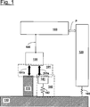
In der in
Als weitere Ausführungsformen können Sensorrahmen und Tragrahmen durch eine starre, bevorzugt isostatische Lagerung verbunden sein. Auch ein Tragrahmen, der gleichzeitig als Sensorrahmen dient, ist denkbar.As further embodiments sensor frame and support frame may be connected by a rigid, preferably isostatic storage. A support frame, which also serves as a sensor frame, is conceivable.
Die Anordnung aus
Die mechanische Anbindung des die beiden Aktuatorantriebe
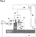
Im Weiteren wird der Aufbau eines Aktuators
Diese Doppelpfeile zeigen zugleich die Richtung der von den beiden Aktuatorteilen
Erfindungsgemäß werden die auf die Wirkung des ersten Aktuatorteils
Gemäß
In weiteren Ausführungsformen können auch die Permanentmagnete beweglich und die Spulen feststehend ausgebildet sein, d. h. es kann eine insofern zu
Des Weiteren können in Ausführungsformen der Erfindung auch mehrere Aktuatoren für die Aktuierung mehrerer Freiheitsgrade, bevorzugt für die Aktuierung von zwei Freiheitsgraden, in einer Aktuatoreinheit zusammengefasst und gemeinsam an den Spiegel angekoppelt werden.Furthermore, in embodiments of the invention, several actuators for the actuation of several degrees of freedom, preferably for the actuation of two degrees of freedom, can be combined in an actuator unit and coupled together to the mirror.
In einer weiteren Ausführungsform kann der Aktuator
Wie schon unter Bezugnahme auf
Im Gegensatz hierzu ist, wie im rechten Teil von
Wenngleich in dem dargestellten Ausführungsbeispiel die Reaktions- bzw. Filtermasse des zwischen dem ersten Aktuatorteil und dem Tragrahmen vorgesehenen mechanischen Filters durch den Permanentmagneten des den ersten Aktuatorteil
Der durch das Feder-Masse-System
Ein möglicher Signalfluss wird anhand einer Ausführungsform beschrieben, wie sie in
Die in
Allgemein kann zur Verwirklichung des erfindungsgemäß effektiv „aufgesplitteten” Aktuators gemäß
In einer bevorzugten Ausgestaltung kann der Tiefpass
Im Ergebnis kann die Filtermasse
Die Projektionsbelichtungsanlage gemäß
Wenn die Erfindung auch anhand spezieller Ausführungsformen beschrieben wurde, erschließen sich für den Fachmann zahlreiche Variationen und alternative Ausführungsformen, z. B. durch Kombination und/oder Austausch von Merkmalen einzelner Ausführungsformen. Dementsprechend versteht es sich für den Fachmann, dass derartige Variationen und alternative Ausführungsformen von der vorliegenden Erfindung mit umfasst sind, und die Reichweite der Erfindung nur im Sinne der beigefügten Patentansprüche und deren Äquivalente beschränkt ist.While the invention has been described with reference to specific embodiments, numerous variations and alternative embodiments will become apparent to those skilled in the art. B. by combination and / or exchange of features of individual embodiments. Accordingly, it will be understood by those skilled in the art that such variations and alternative embodiments are intended to be embraced by the present invention, and the scope of the invention is limited only in terms of the appended claims and their equivalents.
Claims (19)
Priority Applications (5)
| Application Number | Priority Date | Filing Date | Title |
|---|---|---|---|
| DE102011075393A DE102011075393B4 (en) | 2011-05-06 | 2011-05-06 | Arrangement for the actuation of an element in a projection exposure apparatus |
| JP2014508730A JP6121401B2 (en) | 2011-05-06 | 2012-04-12 | Mechanism for operating elements of projection exposure apparatus |
| PCT/EP2012/056628 WO2012152520A1 (en) | 2011-05-06 | 2012-04-12 | Arrangement for actuating an element in a projection exposure apparatus |
| CN201280022137.6A CN103502891B (en) | 2011-05-06 | 2012-04-12 | The device of the element in actuating projection exposure apparatus |
| US14/022,819 US9081292B2 (en) | 2011-05-06 | 2013-09-10 | Arrangement for actuating an element in a projection exposure apparatus |
Applications Claiming Priority (1)
| Application Number | Priority Date | Filing Date | Title |
|---|---|---|---|
| DE102011075393A DE102011075393B4 (en) | 2011-05-06 | 2011-05-06 | Arrangement for the actuation of an element in a projection exposure apparatus |
Publications (2)
| Publication Number | Publication Date |
|---|---|
| DE102011075393A1 DE102011075393A1 (en) | 2012-11-08 |
| DE102011075393B4 true DE102011075393B4 (en) | 2013-08-14 |
Family
ID=47019435
Family Applications (1)
| Application Number | Title | Priority Date | Filing Date |
|---|---|---|---|
| DE102011075393A Expired - Fee Related DE102011075393B4 (en) | 2011-05-06 | 2011-05-06 | Arrangement for the actuation of an element in a projection exposure apparatus |
Country Status (5)
| Country | Link |
|---|---|
| US (1) | US9081292B2 (en) |
| JP (1) | JP6121401B2 (en) |
| CN (1) | CN103502891B (en) |
| DE (1) | DE102011075393B4 (en) |
| WO (1) | WO2012152520A1 (en) |
Families Citing this family (15)
| Publication number | Priority date | Publication date | Assignee | Title |
|---|---|---|---|---|
| WO2013160016A1 (en) | 2012-04-26 | 2013-10-31 | Asml Netherlands B.V. | Lithography apparatus and device manufacturing method |
| DE102013201081A1 (en) * | 2013-01-24 | 2014-03-13 | Carl Zeiss Smt Gmbh | Device for supporting optical device in lithography system, has additional control elements that are connected with auxiliary mass in force-transmitting manner for active attenuation of flexible modes of optical device |
| JP6168957B2 (en) * | 2013-09-30 | 2017-07-26 | キヤノン株式会社 | Optical apparatus, projection optical system, exposure apparatus, and article manufacturing method |
| US10257834B2 (en) * | 2013-12-02 | 2019-04-09 | Sony Corporation | Communications device, infrastructure equipment and methods for receiving downlink control information |
| JP6618921B2 (en) * | 2014-04-17 | 2019-12-11 | エーエスエムエル ネザーランズ ビー.ブイ. | Positioning system, object vibration compensation method, lithographic apparatus, and device manufacturing method |
| JP6371576B2 (en) | 2014-05-02 | 2018-08-08 | キヤノン株式会社 | Optical apparatus, projection optical system, exposure apparatus, and article manufacturing method |
| WO2015173363A1 (en) * | 2014-05-14 | 2015-11-19 | Carl Zeiss Smt Gmbh | Projection lighting system with near-field manipulator |
| DE102015201870A1 (en) | 2015-02-03 | 2016-08-04 | Carl Zeiss Smt Gmbh | Arrangement for position manipulation of an element, in particular in an optical system |
| DE102016202408A1 (en) * | 2016-02-17 | 2017-01-26 | Carl Zeiss Smt Gmbh | Arrangement for position manipulation of an element in an optical system |
| ES2603655B1 (en) * | 2016-04-21 | 2017-09-25 | Consorci Per A La Construcció, Equipament I Explotació Del Laboratori De Llum De Sincrotró | DEVICE AND METHOD OF FORCE APPLICATION IN AN OBJECT |
| DE102016216917A1 (en) * | 2016-09-07 | 2018-03-08 | Carl Zeiss Smt Gmbh | Optical system, in particular lithography system, and method |
| DE102016225900A1 (en) * | 2016-12-21 | 2018-06-21 | Carl Zeiss Smt Gmbh | Tauchspulenaktuator |
| WO2018141520A1 (en) | 2017-02-02 | 2018-08-09 | Asml Netherlands B.V. | Lithographic apparatus, lithographic projection apparatus and device manufacturing method |
| DE102017216458A1 (en) * | 2017-09-18 | 2019-03-21 | Carl Zeiss Smt Gmbh | A method for producing a mirror as an optical component for an optical system of a projection exposure apparatus for projection lithography |
| DE102020208013B3 (en) | 2020-06-29 | 2021-09-02 | Carl Zeiss Smt Gmbh | COMPENSATION OF CREEPING EFFECTS IN A PICTURE DEVICE |
Citations (3)
| Publication number | Priority date | Publication date | Assignee | Title |
|---|---|---|---|---|
| US20050275822A1 (en) * | 2004-06-14 | 2005-12-15 | Asml Netherlands B.V. | Positioning device and device manufacturing method |
| US7443619B2 (en) * | 2005-10-04 | 2008-10-28 | Canon Kabushiki Kaisha | Optical element holding apparatus, exposure apparatus and device manufacturing method |
| US20100321662A1 (en) * | 2008-03-18 | 2010-12-23 | Asml Netherlands B.V. | Actuator System, Lithographic Apparatus, and Device Manufacturing Method |
Family Cites Families (11)
| Publication number | Priority date | Publication date | Assignee | Title |
|---|---|---|---|---|
| TW316874B (en) * | 1995-05-30 | 1997-10-01 | Philips Electronics Nv | |
| US20030019791A1 (en) * | 2001-06-18 | 2003-01-30 | Petronetics, Llc. | Method to upgrade hydrocarbon mixtures |
| EP1321822A1 (en) * | 2001-12-21 | 2003-06-25 | ASML Netherlands B.V. | Lithographic apparatus and device manufacturing method |
| JP4574206B2 (en) * | 2003-04-25 | 2010-11-04 | キヤノン株式会社 | Driving device, exposure apparatus using the same, and device manufacturing method |
| JPWO2005085671A1 (en) * | 2004-03-08 | 2008-01-24 | 株式会社ニコン | Anti-vibration device, exposure apparatus, and anti-vibration method |
| JP2007316132A (en) * | 2006-05-23 | 2007-12-06 | Canon Inc | Reflection apparatus |
| JP5008630B2 (en) * | 2007-10-02 | 2012-08-22 | エーエスエムエル ネザーランズ ビー.ブイ. | Lithographic apparatus and device manufacturing method |
| US8164737B2 (en) * | 2007-10-23 | 2012-04-24 | Asml Netherlands B.V. | Lithographic apparatus having an active damping subassembly |
| NL2003424A (en) * | 2008-10-07 | 2010-04-08 | Asml Netherlands Bv | Projection assembly and lithographic apparartus. |
| EP2295829B1 (en) * | 2009-09-11 | 2016-07-13 | Integrated Dynamics Engineering | Improved active vibration insulation system |
| DE102012202553A1 (en) * | 2012-02-20 | 2013-08-22 | Carl Zeiss Smt Gmbh | LITHOGRAPHY DEVICE WITH DAMPING DEVICE |
-
2011
- 2011-05-06 DE DE102011075393A patent/DE102011075393B4/en not_active Expired - Fee Related
-
2012
- 2012-04-12 JP JP2014508730A patent/JP6121401B2/en active Active
- 2012-04-12 CN CN201280022137.6A patent/CN103502891B/en active Active
- 2012-04-12 WO PCT/EP2012/056628 patent/WO2012152520A1/en active Application Filing
-
2013
- 2013-09-10 US US14/022,819 patent/US9081292B2/en active Active
Patent Citations (3)
| Publication number | Priority date | Publication date | Assignee | Title |
|---|---|---|---|---|
| US20050275822A1 (en) * | 2004-06-14 | 2005-12-15 | Asml Netherlands B.V. | Positioning device and device manufacturing method |
| US7443619B2 (en) * | 2005-10-04 | 2008-10-28 | Canon Kabushiki Kaisha | Optical element holding apparatus, exposure apparatus and device manufacturing method |
| US20100321662A1 (en) * | 2008-03-18 | 2010-12-23 | Asml Netherlands B.V. | Actuator System, Lithographic Apparatus, and Device Manufacturing Method |
Also Published As
| Publication number | Publication date |
|---|---|
| JP6121401B2 (en) | 2017-04-26 |
| JP2014519186A (en) | 2014-08-07 |
| CN103502891A (en) | 2014-01-08 |
| US20140016109A1 (en) | 2014-01-16 |
| WO2012152520A1 (en) | 2012-11-15 |
| DE102011075393A1 (en) | 2012-11-08 |
| CN103502891B (en) | 2016-11-02 |
| US9081292B2 (en) | 2015-07-14 |
Similar Documents
| Publication | Publication Date | Title |
|---|---|---|
| DE102011075393B4 (en) | Arrangement for the actuation of an element in a projection exposure apparatus | |
| DE102013201082A1 (en) | Arrangement for actuation of optical element e.g. mirror in microlithography projection exposure system, has actuators that are arranged in natural vibration mode of the optical element | |
| DE102011080318A1 (en) | Damping arrangement for the dissipation of vibration energy of an element in a system, in particular in a microlithographic projection exposure apparatus | |
| DE60033773T2 (en) | Lithographic apparatus with a balanced positioning system | |
| DE102011007917A1 (en) | Arrangement for the actuation of an element in a microlithographic projection exposure apparatus | |
| DE102010029905A1 (en) | Optical system of a microlithographic projection exposure apparatus | |
| DE102008007449A1 (en) | Illumination optics for illuminating an object field of a projection exposure apparatus for microlithography | |
| DE102011006024A1 (en) | Arrangement for vibration isolation of a payload | |
| DE102014218969A1 (en) | Optical arrangement of a microlithographic projection exposure apparatus | |
| DE102011083888A1 (en) | Imaging catoptric EUV projection optics | |
| DE102012220925A1 (en) | Damping arrangement for dissipating vibrational energy of e.g. mirror, in microlithographic projection exposure apparatus, has flux guide producing magnetic circuit between two components by gap | |
| DE102018132436A1 (en) | Assembly, in particular in a microlithographic projection exposure apparatus | |
| DE102011004299A1 (en) | Arrangement for supporting mirror in extreme UV projection exposure system for use during manufacture of micro-structured component for e.g. LCD, has damping element attenuating pin arranged between actuator and mirror in lateral direction | |
| DE102015201870A1 (en) | Arrangement for position manipulation of an element, in particular in an optical system | |
| DE102014204523A1 (en) | Vibration-compensated optical system, lithographic apparatus and method | |
| DE102018219375A1 (en) | Load-bearing support structure | |
| DE102012205045A1 (en) | Optical system of a microlithographic projection exposure apparatus | |
| EP3961305A2 (en) | Compensation of creep effects in imaging device | |
| DE102012214232A1 (en) | Bearing device for mirror of mirror arrangement for projection exposure system, has three supports, and support bearing, which is formed such that only force component is transferred in direction opposite to gravitational force | |
| EP3964893A1 (en) | Compensation of creep effects in imaging device | |
| DE102015210484A1 (en) | Damping arrangement for damping oscillatory movements of an element in a system | |
| DE102015224934A1 (en) | Optical device, optical device, projection system and lithography system | |
| DE102019218305A1 (en) | Device for mounting a component of a projection exposure system | |
| DE102013209028A1 (en) | Component of microlithographic projection exposure system has magnet assembly which produces magnetic field on element of projection exposure system such that ratio of total mass of element and radial inner magnetic rings is preset | |
| DE102011077315A1 (en) | Optical arrangement for projection lens of extreme UV (EUV) projection exposure system for manufacturing e.g. LCD, has diaphragm that is arranged outside workspace of projecting lens, based on operating position of positioning device |
Legal Events
| Date | Code | Title | Description |
|---|---|---|---|
| R012 | Request for examination validly filed | ||
| R016 | Response to examination communication | ||
| R018 | Grant decision by examination section/examining division | ||
| R020 | Patent grant now final |
Effective date: 20131115 |
|
| R119 | Application deemed withdrawn, or ip right lapsed, due to non-payment of renewal fee |