DE102010051637A1 - Method for determining a basic system of diffractive gratings for color fringe correction of spectacle lenses - Google Patents
Method for determining a basic system of diffractive gratings for color fringe correction of spectacle lenses Download PDFInfo
- Publication number
- DE102010051637A1 DE102010051637A1 DE102010051637A DE102010051637A DE102010051637A1 DE 102010051637 A1 DE102010051637 A1 DE 102010051637A1 DE 102010051637 A DE102010051637 A DE 102010051637A DE 102010051637 A DE102010051637 A DE 102010051637A DE 102010051637 A1 DE102010051637 A1 DE 102010051637A1
- Authority
- DE
- Germany
- Prior art keywords
- base
- series
- spectacle lens
- glasses
- grating
- Prior art date
- Legal status (The legal status is an assumption and is not a legal conclusion. Google has not performed a legal analysis and makes no representation as to the accuracy of the status listed.)
- Granted
Links
Images

Classifications
-
- G—PHYSICS
- G02—OPTICS
- G02C—SPECTACLES; SUNGLASSES OR GOGGLES INSOFAR AS THEY HAVE THE SAME FEATURES AS SPECTACLES; CONTACT LENSES
- G02C7/00—Optical parts
- G02C7/02—Lenses; Lens systems ; Methods of designing lenses
- G02C7/022—Ophthalmic lenses having special refractive features achieved by special materials or material structures
-
- G—PHYSICS
- G02—OPTICS
- G02C—SPECTACLES; SUNGLASSES OR GOGGLES INSOFAR AS THEY HAVE THE SAME FEATURES AS SPECTACLES; CONTACT LENSES
- G02C7/00—Optical parts
- G02C7/02—Lenses; Lens systems ; Methods of designing lenses
-
- G—PHYSICS
- G02—OPTICS
- G02C—SPECTACLES; SUNGLASSES OR GOGGLES INSOFAR AS THEY HAVE THE SAME FEATURES AS SPECTACLES; CONTACT LENSES
- G02C7/00—Optical parts
- G02C7/02—Lenses; Lens systems ; Methods of designing lenses
- G02C7/024—Methods of designing ophthalmic lenses
-
- G—PHYSICS
- G02—OPTICS
- G02C—SPECTACLES; SUNGLASSES OR GOGGLES INSOFAR AS THEY HAVE THE SAME FEATURES AS SPECTACLES; CONTACT LENSES
- G02C7/00—Optical parts
- G02C7/02—Lenses; Lens systems ; Methods of designing lenses
- G02C7/024—Methods of designing ophthalmic lenses
- G02C7/028—Special mathematical design techniques
-
- G—PHYSICS
- G02—OPTICS
- G02C—SPECTACLES; SUNGLASSES OR GOGGLES INSOFAR AS THEY HAVE THE SAME FEATURES AS SPECTACLES; CONTACT LENSES
- G02C7/00—Optical parts
- G02C7/02—Lenses; Lens systems ; Methods of designing lenses
- G02C7/06—Lenses; Lens systems ; Methods of designing lenses bifocal; multifocal ; progressive
- G02C7/061—Spectacle lenses with progressively varying focal power
- G02C7/068—Special properties achieved by the combination of the front and back surfaces
-
- G—PHYSICS
- G02—OPTICS
- G02C—SPECTACLES; SUNGLASSES OR GOGGLES INSOFAR AS THEY HAVE THE SAME FEATURES AS SPECTACLES; CONTACT LENSES
- G02C2202/00—Generic optical aspects applicable to one or more of the subgroups of G02C7/00
- G02C2202/20—Diffractive and Fresnel lenses or lens portions
-
- G—PHYSICS
- G02—OPTICS
- G02C—SPECTACLES; SUNGLASSES OR GOGGLES INSOFAR AS THEY HAVE THE SAME FEATURES AS SPECTACLES; CONTACT LENSES
- G02C2202/00—Generic optical aspects applicable to one or more of the subgroups of G02C7/00
- G02C2202/22—Correction of higher order and chromatic aberrations, wave front measurement and calculation
Abstract
Die Erfindung betrift insbesondere ein Verfahren zum Herstellen einer Serie von Basisgläsern, welche einen vorgegebenen Wirkungsbereich abdecken, wobei jedes Basisglas der Serie eine von den Basiswirkungen der anderen Basisgläser der Serie unterschiedliche Basiswirkung hat und zumindest ein diffraktives Basisgitter aufweist, wobei das Verfahren die Schritte umfasst: Festlegen der Basiswirkungen eines jeden Basisglases der Serie; Berechnen des Basisgitters eines jeden Basisglases der Serie derart, den Farbsaums des jeweiligen Basisglases mit der festgelegten Basiswirkung in einem vorgegebenen Bereich des Brillenglases zu minimieren.The invention relates in particular to a method for producing a series of base glasses which cover a predetermined area of action, each base glass of the series having a different base effect from the base effects of the other base glasses in the series and having at least one diffractive base grating, the method comprising the steps: Establishing the basic effects of each basic glass in the series Calculation of the basic grating of each basic lens in the series in such a way as to minimize the color fringing of the respective basic lens with the specified basic effect in a predetermined area of the spectacle lens.
Description
Ein Brillenglas, das kein Planglas ist, hat außer in der optischen Mitte neben der dioptrischen Wirkung auch immer eine prismatische Wirkung. Ist das Glas aus einem einheitlichen Material gefertigt, dann ist je nach Material und dessen Abbezahl mit dieser prismatischen Wirkung immer auch ein mehr oder weniger starker Farbsaum, also ein Farbquerfehler, verbunden. Dieser ist umso stärker, je größer die Wirkung des Glases ist, je weiter der Beobachtungspunkt von der optischen Mitte entfernt ist und je kleiner die Abbezahl ist. Insbesondere tritt der Farbsaum bei höherbrechenden optischen Materialien auf, welche zur Reduktion der Dicke der Brillengläser häufig verwendet werden. Da dieser Farbsaum die Abbildungsqualität beeinträchtigt, besteht Interesse daran, diesen zu korrigieren. Eine Korrektur des Farbsaums kann mit einem diffraktiven Gitter erzielt werden.A spectacle lens that is not a plano-glass, except for the optical center, has a prismatic effect in addition to the dioptric effect. If the glass is made of a uniform material, depending on the material and its Abbezahl with this prismatic effect always a more or less strong color fringing, so a lateral chromatic aberration, connected. This is the stronger, the greater the effect of the glass, the farther the observation point is from the optical center and the smaller the Abbe number. In particular, the fringing occurs with higher refractive optical materials which are often used to reduce the thickness of the spectacle lenses. Since this color fringe affects the image quality, there is interest in correcting it. A correction of the color fringe can be achieved with a diffractive grating.
Es ist eine Aufgabe der Erfindung ein effizientes, kostengünstiges und schnelles Verfahren zum Herstellen von farbsaumkorrigierten Brillengläsern sowie entsprechende Vorrichtungen bereitzustellen. Ebenfalls ist es eine Aufgabe der Erfindung eine Serie von Brillengläsern bereitzustellen, wobei möglichst wenige Gitterausführungen ausreichend sind, um das gesamte Wirkungsspektrum abzudecken.It is an object of the invention to provide an efficient, inexpensive and fast method for producing color-fringe-corrected spectacle lenses and corresponding devices. It is also an object of the invention to provide a series of spectacle lenses, wherein as few grating designs are sufficient to cover the entire spectrum of action.
Diese Aufgabe wird durch ein Verfahren zum Herstellen einer Serie von farbsaumkorrigierten Basisgläsern mit den im Anspruch 1 angegebenen Merkmalen, eine Vorrichtung zum Herstellen einer Serie von farbsaumkorrigierten Basisgläsern mit den im Anspruch 11 angegebenen Merkmalen, eine Serie von Basisgläsern mit den im Anspruch 12 angegebenen Merkmalen, ein Verfahren zum Herstellen eines Brillenglases mit den im Anspruch 24 angegebenen Merkmalen, eine Serie von Brillengläsern mit den im Anspruch 26 angegebenen Merkmalen, ein progressives Brillenglas mit den im Anspruch 32 angegebenen Merkmalen und ein astigmatisches Brillenglas mit den im Anspruch 33 angegebenen Merkmalen gelöst. Bevorzugte Ausführungsformen sind Gegenstand der abhängigen Ansprüche.This object is achieved by a method for producing a series of color fringe-corrected base glasses having the features specified in
Gemäß einem ersten Aspekt der Erfindung wird ein Verfahren zum Herstellen einer Serie von Basisgläsern, welche einen vorgegebenen Wirkungsbereich abdecken, vorgeschlagen. Jedes Basisglas der Serie hat eine von den Basiswirkungen der anderen Basisgläser der Serie unterschiedliche Basiswirkung und weist zumindest ein diffraktives Basisgitter auf. Das Verfahren umfasst die Schritte
Festlegen der Basiswirkungen eines jeden Basisglases der Serie;
Berechnen des Basisgitters eines jeden Basisglases der Serie derart, den Farbsaums des jeweiligen Basisglases mit der festgelegten Basiswirkung in einem vorgegebenen Bereich des Brillenglases zu minimieren.According to a first aspect of the invention, a method is proposed for producing a series of base glasses which cover a predetermined range of action. Each base glass in the series has a base effect different from the basic effects of the other base glasses of the series and has at least one diffractive base lattice. The method comprises the steps
Determining the basis effects of each base glass of the series;
Calculating the base grating of each base glass of the series so as to minimize the color fringe of the respective base glass having the fixed base effect in a predetermined region of the spectacle lens.
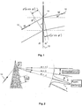
Der Farbsaum von optischen Elementen (z. B. von Brillengläsern) beruht darauf, dass die beiden kombinierten refraktiven Grenzflächen des optischen Elements eine wellenlängenabhängige prismatische Wirkung Prref besitzen. Mittels eines diffraktiven Gitters, welches auf zumindest einer der refraktiven Grenzflächen des optischen Elements aufgebracht wird, ist es möglich, eine Farbsaumkorrektur zu erzielen. Wie nachfolgend gezeigt wird, kann bei geeigneter Auslegung oder Dimensionierung des diffraktiven Gitters (insbesondere der Periode d des diffraktiven Gitters) im Idealfall eine nahezu vollständige Korrektur des Farbsaums eines Brillenglases für eine gegebene sphärozylindrische Wirkungsverteilung, für einen gegebenen Objektabstand und für eine gegebene Gebrauchssituation erzielt werden. Anders ausgedrückt kann der Farbsaum eines Brillenglases durch ein Gitter kompensiert werden, welches individuell für das Brillenglas (insbesondere die vorgegebene sphärozylindrische Wirkung), für den vorgegebenen Objektanstand und für die vorgegebene Gebrauchssituation berechnet ist. Im Allgemeinen sind die Gitterlinien dieses Gitters asymmetrische, geschlossene Kurven.The color fringe of optical elements (for example of spectacle lenses) is based on the fact that the two combined refractive interfaces of the optical element have a wavelength-dependent prismatic effect Pr ref . By means of a diffractive grating, which is applied to at least one of the refractive interfaces of the optical element, it is possible to achieve a color fringe correction. As will be shown below, with a suitable design or dimensioning of the diffractive grating (in particular the period d of the diffractive grating), an almost complete correction of the color fringe of a spectacle lens can be achieved for a given spherocylindrical effect distribution, for a given object distance and for a given usage situation , In other words, the color fringe of a spectacle lens can be compensated by a grating which is calculated individually for the spectacle lens (in particular the predetermined sphero-cylindrical effect), for the given object status and for the given situation of use. In general, the grid lines of this grid are asymmetric, closed curves.
Die Erfindung basiert auf der überraschenden Erkenntnis, dass auch dann, wenn es Abweichungen von dem vorgegebenen Objektabstand, von der vorgegebenen Gebrauchssituation oder der vorgegebenen sphärozylindrischen Wirkungsverteilung gibt oder selbst in dem Fall, dass das Glas überhaupt kein Einstärkenglas sondern z. B. ein progressives Glass ist, ein und dasselbe Gitter den Farbquerfehler immerhin noch weit besser kompensieren kann, als wenn überhaupt kein Gitter vorhanden wäre. Insbesondere hat sich überraschenderweise herausgestellt, dass Abweichungen im Objektabstand oder in der Gebrauchssituation keinen allzu großen Einfluss auf die Fähigkeit eines Gitters, den Farbquerfehler gut zu kompensieren, haben. Es ist ferner erkannt worden, dass im Gegensatz dazu die Abweichungen der tatsächlichen sphärozylindrischen Wirkungsverteilung von der gegebenen Wirkungsverteilung, für die das Gitter ausgelegt ist, in bestimmten Grenzen sein müssen, um eine akzeptable Korrektur des Farbsaums zu erzielen.The invention is based on the surprising finding that even if there are deviations from the predetermined object distance, from the given use situation or the predetermined spherocylindrical distribution of effects or even in the case that the glass is not a single-crystal but z. B. is a progressive glass, one and the same grid can still compensate for the lateral chromatic aberration far better than if no grid at all. In particular, it has surprisingly been found that deviations in the object distance or in the situation of use do not have too great an influence on the ability of a grating to compensate the lateral color aberration well. It has also been recognized that, in contrast, the deviations of the actual spherocylindrical response distribution from the given distribution of efficiencies for which the grid is designed must be within certain limits to achieve acceptable color fringe correction.
Die Erfindung schlägt daher vor, analog zum Blank-Konzept bei der Herstellung von konventionellen Brillengläsern, eine beschränkte Anzahl von unterschiedlichen diffraktiven Gittern zu verwenden, um einen gesamten, vorgegebenen Wirkungsbereich abzudecken. Die Basisgitter können vorgefertigt werden, wobei bei der Herstellung eines Brillenglases ein geeignetes Basisgitter ausgewählt wird.The invention therefore proposes to use a limited number of different diffractive gratings, analogous to the blank concept in the production of conventional spectacle lenses to cover the entire scope of application. The base grids can be prefabricated, wherein a suitable base grille is selected during the production of a spectacle lens.
Mit der vorgeschlagenen Vorgehensweise kann ein System aus einigen wenigen diffraktiven Gittern bzw. aus wenigen Basisgläsern mit Gittern (z. B. ungefähr 5 bis ungefähr 20) bereitgestellt werden, so dass dessen Aufbringung auf einer der Grenzflächen eines Basisglases den Farbsaum (Farbquerfehler) für eine gegebene dioptrische Basiswirkung ideal und für benachbarte Wirkungen noch akzeptabel kompensiert. Ebenfalls ist eine Anordnung des Gitters als innenliegende Struktur, beispielsweise eines Compound-Systems, möglich. Dadurch kann der Berechungs- und/oder Fertigungsaufwand für die Herstellung von farbsaumkorrigierten Gläsern erheblich reduziert werden. Somit ist es möglich, farbsaumkorrigierte Brillengläser mit beliebiger Wirkung innerhalb eines relativ breiten Wirkungsbereichs effizient, schnell und kostengünstig herzustellen. Die Brillengläser können insbesondere Einstärkengläser oder Mehrstärkengläser bzw. Gleitsichtgläser sein. Der Wirkungsbereich kann z. B. von –12 dpt bis +12 dpt sphärische Wirkung und/oder bis 6 dpt astigmatische Wirkung (Zylinder) und/oder eine Addition bis 3,5 dpt umfassen. Der Wirkungsbereich kann ebenfalls ein anderer Wirkungsbereich sein.With the proposed approach, a system of a few diffractive gratings or a few base glasses with gratings (eg, about 5 to about 20) may be provided so that its application on one of the interfaces of a base glass will create the color fringe (lateral chromatic aberration) for one given dioptric basis effect ideal and for neighboring effects still acceptable compensated. Likewise, an arrangement of the grid as an internal structure, for example of a compound system, is possible. As a result, the calculation and / or production costs for the production of color fringe-corrected glasses can be considerably reduced. Thus, it is possible to fabricate color-corrected eyeglass lenses with any effect within a relatively wide range of effectiveness efficiently, quickly, and inexpensively. The spectacle lenses may in particular be single-vision lenses or multifocal lenses or progressive lenses. The sphere of action can, for. B. from -12 dpt to +12 dpt spherical effect and / or up to 6 dpt astigmatic effect (cylinder) and / or addition to 3.5 dpt include. The area of effect can also be another area of influence.
Ebenfalls ist es möglich, eine Serie von Brillengläsern bereitzustellen, wobei möglichst wenige Gitterausführungen ausreichend sind, um das gesamte Wirkungsspektrum abzudecken.It is also possible to provide a series of spectacle lenses, wherein as few grating designs are sufficient to cover the entire spectrum of action.
Unter dem Begriff „diffraktives Gitter” im Sinne der vorliegenden Anmeldung wird jedes phasen- und/oder amplitudenmodulierende bzw. – ändernde optische Element verstanden, bei welchem Beugungseffekte von Relevanz sind. Insbesondere ist ein phasenänderndes optisches Element (POE) ein Element, welches phasenverzögernd oder phasenmodulierend ist, und zwar so, dass die Änderung der optischen Weglänge durch Hinzufügen des Elements vom Durchtrittspunkt des Strahls abhängt. Das diffraktive Gitter kann durch ein diffraktives optisches Element (Diffractive Optical Element oder DOE) realisiert werden oder durch jede andere Art der Phasen- und/oder Amplitudenmodulation.For the purposes of the present application, the term "diffractive grating" is understood to mean any phase and / or amplitude modulating or changing optical element in which diffraction effects are of relevance. In particular, a phase changing optical element (POE) is an element which is phase delaying or phase modulating, such that the change in the optical path length depends on the point of passage of the beam by adding the element. The diffractive grating can be realized by a diffractive optical element (DOE) or by any other type of phase and / or amplitude modulation.
Das diffraktive Gitter umfasst in der Regel eine im Wesentlichen regelmäßige, vorzugsweise periodische oder quasi-periodische, linienartige Anordnung von Strukturen oder Bereichen, in denen das Licht so beeinflusst wird, dass Beugungseffekte von Relevanz sind. Das diffraktive Gitter kann sowohl ein fein strukturiertes diffraktives Gitter als auch ein grob strukturiertes diffraktives Gitter (wie z. B. MOD = Multi-Order-Diffraction Gitter) sein. Das diffraktive Gitter kann zum Beispiel ein Transmissionsgitter, ein mechanisch geteiltes Gitter, insbesondere ein Sägezahn- oder Blazegitter, ein holographisches Gitter, ein Gitter, welches durch eine dünne Folie oder Schicht mit variierendem Brechungsindex (Gradient-Index-Material) realisiert wird, sein. Die Strukturen der eingesetzten diffraktiven Gitter können statisch oder insbesondere elektrisch schaltbar sein. Verfahren zum Herstellen von statischen oder schaltbaren diffraktiven Gittern sind aus dem Stand der Technik bekannt.The diffractive grating usually comprises a substantially regular, preferably periodic or quasi-periodic, line-like arrangement of structures or regions in which the light is influenced so that diffraction effects are of relevance. The diffractive grating may be both a finely structured diffractive grating and a coarsely structured diffractive grating (such as MOD = multi-order diffraction grating). The diffractive grating may, for example, be a transmission grating, a mechanically split grating, in particular a sawtooth or blazed grating, a holographic grating, a grating realized by a thin film or layer of varying refractive index (gradient index material). The structures of the diffractive gratings used can be static or in particular electrically switchable. Methods of making static or switchable diffractive gratings are known in the art.
Vorzugsweise werden diffraktive Gitter eingesetzt, bei welchen der Gangunterschied zwischen zwei benachbarten Gitterlinien typischerweise einer Beugungsordnung von |m| = 1 bis |m| = 4 entspricht. Ebenfalls ist es möglich, ein MOD-Gitter zu verwenden, bei welchem der Gangunterschied typischerweise in der Größenordnung |m| ≈ 20 liegt.Preferably, diffractive gratings are used in which the path difference between two adjacent grating lines typically has a diffraction order of | m | = 1 to | m | = 4 corresponds. It is also possible to use a MOD grid in which the path difference is typically of the order of | m | ≈ 20 lies.
Das diffraktive Gitter kann in der ersten Beugungsordnung verwendet werden. Es ist jedoch möglich, das diffraktive Gitter nicht in erster Beugungsordnung, sondern in einer höheren Ordnung zu verwenden. Das diffraktive Gitter kann eine Grenzfläche aufweisen, welche gegen Luft berechnet wird. Es ist ebenfalls möglich, eine Grenzfläche des diffraktiven Gitters nicht gegen Luft, sondern gegen ein anderes Material zu berechnen.The diffractive grating can be used in the first diffraction order. However, it is possible to use the diffractive grating not in the first diffraction order but in a higher order. The diffractive grating may have an interface calculated against air. It is also possible to calculate an interface of the diffractive grating not against air but against another material.
Das Profil des diffraktiven Gitters kann geeignet festgelegt oder dimensioniert werden. Das Profil des Gitters wird vorzugsweise so festgelegt, dass die Beugungseffizienz für eine bestimmte Beugungsordnung maximal ist. Anders ausgedrückt kann das Profil des Gitters so festgelegt werden, dass sich die Intensität des gebeugten Lichts möglichst in eine Beugungsordnung konzentriert. Vorzugsweise ist das Gitterprofil sägezahnförmig. Insbesondere kann eine sägezahnförmige (engl. blazed) Grenzfläche zwischen einem dispergierenden Grundmaterial und Luft eingesetzt werden. Die laterale Skala des Gitters, d. h. die Gitterkonstante, kann in der Größenordnung der Wellenlänge liegen. Es ist jedoch auch möglich, diffraktive Gitter einzusetzen, wobei die Gitterkonstante nicht in der Größenordnung der Wellenlänge liegt, sondern um bis zu einen Faktor 100 darüber. Das diffraktive Gitter kann mit einem anderen Gitter überlagert/kombiniert werden, z. B. mit einem Fresnel-Gitter, welches eine von Null unterschiedliche dioptrische Wirkung aufweist. Die Periode des Gittes kann – wie nachfolgend beschrieben wird – geeignet bestimmt werden.The profile of the diffractive grating can be suitably determined or dimensioned. The profile of the grating is preferably set so that the diffraction efficiency is maximal for a given diffraction order. In other words, the profile of the grating can be set so that the intensity of the diffracted light is concentrated as much as possible in a diffraction order. Preferably, the grid profile is sawtooth. In particular, a saw-toothed (blazed) interface between a dispersing base material and air can be used. The lateral scale of the grid, d. H. the lattice constant, may be of the order of the wavelength. However, it is also possible to use diffractive gratings, wherein the lattice constant is not in the order of the wavelength, but by up to a factor of 100 above. The diffractive grating may be superimposed / combined with another grating, e.g. B. with a Fresnel grating, which has a dioptric power different from zero. The period of the gating can be suitably determined as described below.
Das Gitter kann sich im Wesentlichen über den gesamten Blickwinkelbereich bzw. über den gesamten Bereich des Basisglases erstrecken. Das Gitter kann in zentrierter Weise um einen vorgegebenen Bezugspunkt, insbesondere um den Prismenbezugspunkt oder um den Zentrier- bzw. Anpaßpunkt, oder um die geometrische Mitte des rohrunden Basisglases angeordnet werden. Es ist jedoch ebenfalls möglich, das Gitter dezentriert anzuordnen. The grid may extend substantially over the entire viewing angle range or over the entire area of the base glass. The grid can be arranged in a centered manner about a given reference point, in particular around the prism reference point or about the centering or fitting point, or about the geometric center of the tubular base glass. However, it is also possible to arrange the grid decentered.
Das Gitter kann auf eine oder auf beide refraktive Grenzflächen des Basisglases aufgebracht werden. Es ist jedoch auch möglich, ein Compound-System vorzusehen, welches aus einem Grundglas und einem Deckglas aufgebaut ist, wobei die Gitterstrukturen auf den geschützten Innenseiten des Grundglases und/oder des Deckglases (d. h. die sich gegenüber stehenden Seiten des Grund- und des Deckglases) aufgebracht sind.The grating can be applied to one or both refractive interfaces of the base glass. However, it is also possible to provide a compound system which is made up of a base glass and a cover glass, wherein the grid structures on the protected inner sides of the base glass and / or the cover glass (ie the opposite sides of the base and cover glass) are applied.
Ein Basisglas im Sinne der vorliegenden Anmeldung kann jedes optische Element sein, welches zumindest ein diffraktives Gitter aufweist. Ein Basisglass kann z. B. ein sogenanntes „halbfertiges Brillenglas” oder ein Blank sein, wobei lediglich eine Fläche, vorzugsweise die Fläche, welche das Gitter trägt, fertig bearbeitet ist, und wobei die gegenüberliegende Fläche in Abhängigkeit von Rezeptdaten eines bestimmten Brillenträgers nachträglich bearbeitet wird. Insbesondere kann die gegenüberliegende Fläche derart bearbeitet werden, dass in zumindest einem vorgegebenen Bezugspunkt des Brillenglases (z. B. in einem Zentrier- oder Anpaßpunkt, in einem Fernbezugspunkt und/oder in einem Nahbezugspunkt) eine Sollwirkung des Brillenglases erzielt wird. Das Basisglas kann ebenfalls ein sogenanntes „Compound-System” sein, welches zumindest ein Grundglas und ein Deckglas aufweist.A base glass in the sense of the present application can be any optical element which has at least one diffractive grating. A base glass can z. As a so-called "semi-finished lens" or a blank, with only one surface, preferably the surface which carries the grid, is finished, and wherein the opposite surface is processed in dependence on recipe data of a particular wearer of glasses subsequently. In particular, the opposite surface can be processed in such a way that a target effect of the spectacle lens is achieved in at least one predetermined reference point of the spectacle lens (eg in a centering or fitting point, in a distance reference point and / or in a near reference point). The base glass can also be a so-called "compound system" which has at least one base glass and a cover glass.
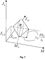
Unter der Wirkung eines optischen Elements wird die gesamte dioptrische Wirkung des optischen Elements verstanden, welche durch den refraktiven Anteil und den diffraktiven Anteil zustande kommt (wie nachfolgend im Detail beschrieben wird), und welche die gesamte sphärische Wirkung und/oder die astigmatische Wirkung und gegebenenfalls die prismatische Wirkung umfasst. Ein Maß für den mittleren sphärischen Anteil der sphärozylindrischen Wirkung eines Brillenglases ist das sphärische Äquivalent. Ferner kann die sphärozylindrische Wirkung – wie nachfolgend im Detail beschrieben – mittels Powervektoren beschrieben werden.By the action of an optical element is meant the total dioptric power of the optical element, which is due to the refractive portion and the diffractive portion (as will be described in detail below), and which is the total spherical and / or astigmatic and, if necessary which includes prismatic action. A measure of the mean spherical portion of the spherocylindrical effect of a spectacle lens is the spherical equivalent. Furthermore, the sphero-cylindrical effect - as described in detail below - can be described by means of power vectors.
Unter der refraktiven Wirkung wird die Wirkung eines optischen Elements verstanden, welche aufgrund der Flächenkrümmungen zustande kommt. Bei einem rotationssymmetrischen Brillenglas umfasst die refraktive Wirkung des Brillenglases die sphärische Wirkung des Brillenglases in einem vorgegebenen Bezugspunkt, z. B. in dem Scheitel. Bei einem astigmatischen Brillenglas kommt zu der refraktiven sphärischen Wirkung die astigmatische refraktive Wirkung des Brillenglases hinzu. Die gesamte refraktive dioptrische Wirkung des Brillenglases kann in diesem Fall die refraktive sphärozylindrische Wirkung des Brillenglases sein.The refractive effect is understood to mean the effect of an optical element which is due to the surface curvatures. In a rotationally symmetrical spectacle lens, the refractive effect of the spectacle lens comprises the spherical effect of the spectacle lens in a predetermined reference point, for. In the apex. In the case of an astigmatic spectacle lens, the astigmatic refractive effect of the spectacle lens is added to the refractive spherical effect. The total refractive dioptric power of the spectacle lens in this case can be the refractive spherocylindrical effect of the spectacle lens.
Vorzugsweise sind die Basisgläser sphärozylindrische oder sphärische Einstärkengläser. Vorzugsweise ist das diffraktive Gitter auf eine der beiden refraktiven Grenzflächen (Vorder- oder Rückfläche) des Basisglases aufgebracht. Die gegenüberliegende Fläche kann zur Anpassung an eine Rezeptwirkung dienen, d. h. eine Rezeptfläche darstellen.Preferably, the base glasses are spherocylindrical or spherical single vision glasses. Preferably, the diffractive grating is applied to one of the two refractive interfaces (front or back surface) of the base glass. The opposite surface may serve to conform to a recipe effect, i. H. represent a recipe area.
Das Berechnen des Basisgitters jedes einzelnen Brillenglases kann eine Optimierung des Gitters und/oder zumindest einer der refraktiven Flächen des Basisglases umfassen. Vorzugsweise umfasst das Berechnen des Basisgitters eine simultane Optimierung zumindest einer der refraktiven Flächen des Basisglases und des Basisgitters. Vorzugsweise ist die zumindest eine refraktive Fläche die Fläche des Basisglases, welche das Gitter trägt. Die Optimierung erfolgt vorzugsweise in einer vorgegebenen Gebrauchsstellung des Basisglases. Die Gebrauchsstellung kann insbesondere durch den Fassungsscheibenwinkel, die Vorneigung, den Hornhautscheitelabstand, die Pupillendistanz, und gegebenenfalls weitere Parameter charakterisiert werden. Die Parameter der Gebrauchsstellung können durchschnittliche Parameter sein. Ebenfalls wird vorzugsweise ein vorgegebener Objektabstand, vorzugsweise als Funktion der Blickrichtung, berücksichtigt.The calculation of the base grating of each individual spectacle lens may include an optimization of the grating and / or at least one of the refractive surfaces of the base glass. Preferably, computing the base grating comprises simultaneously optimizing at least one of the refractive surfaces of the base glass and the base grating. Preferably, the at least one refractive surface is the surface of the base glass which supports the grid. The optimization is preferably carried out in a predetermined position of use of the base glass. The position of use can be characterized in particular by the frame disc angle, the preadjustment, the corneal vertex distance, the pupillary distance, and optionally further parameters. The parameters of the position of use can be average parameters. Also preferably a predetermined object distance, preferably as a function of the viewing direction, is taken into account.
Vorzugsweise erfolgt die Optimierung derart, Abbildungsfehler zumindest zweiter Ordnung zu minimieren. Die Optimierung kann eine Minimierung einer polychromatischen Zielfunktion umfassen, in welcher der Farbsaum unmittelbar als Zielgröße oder mittelbar durch eine Wellenlängenabhängigkeit der in der Zielfunktion eingehenden Größen eingeht. Die Abbildungsfehler zweiter oder höherer Ordnung werden vorzugsweise mittels einer Wellenfrontdurchrechnung unter Berücksichtigung des Basisgitters und der Gebrauchsstellung des Brillenglases ermittelt.The optimization is preferably carried out in such a way as to minimize aberrations of at least second order. The optimization may include a minimization of a polychromatic objective function in which the fringe immediately enters as a target size or indirectly through a wavelength dependency of the quantities entering the target function. The aberrations of the second or higher order are preferably determined by means of a wavefront analysis, taking into account the basic grating and the position of use of the spectacle lens.
Die polychromatische Zielfunktion kann z. B. eine Zielfunktion des Typs: 
In den obigen Formeln bezeichnen
Fmonochrom (λ) eine monochromatische Zielfunktion für die Wellenlänge λ;
gFLF(i) die Gewichtung des Farblängsfehlers an der i-ten Bewertungsstelle des optischen Elements;
gFQF(i) die Gewichtung des Farbquerfehlers an der i-ten Bewertungsstelle des optischen Elements;
f(
ΔφSK (i, λ2, λ1) den Winkel zwischen den objektseitigen Hauptstrahlen für unterschiedlichen Wellenlängen λ1 und
und g(ΔφSK(i, λ2, λ1)) eine Funktion des Winkels zwischen den objektseitigen Hauptstrahlen für unterschiedlichen Wellenlängen λ1 und λ2.In the above formulas denote
F monochrome (λ) a monochromatic objective function for the wavelength λ;
g FLF (i) the weighting of the longitudinal chromatic aberration at the i-th evaluation point of the optical element;
g FQF (i) the weighting of the lateral chromatic aberration at the i-th evaluation point of the optical element;
f (
Δφ SK (i, λ 2 , λ 1 ) the angle between the object-side principal rays for different wavelengths λ 1 and
and g (Δφ SK (i, λ 2 , λ 1 )) is a function of the angle between the object-side principal rays for different wavelengths λ 1 and λ 2 .
Eine Zielfunktion des ersten Typs kommt insbesondere dadurch zustande, dass eine beliebige monochromatische Zielfunktion als Funktion der Wellenlänge aufgefasst wird und für zumindest zwei unterschiedliche Wellenlängen ausgewertet und über den Satz von zumindest zwei unterschiedlichen Wellenlängen summiert wird. Wie bereits oben ausgeführt, werden in diesem Fall die Farbfehler des optischen Elements mittelbar durch die Wellenlängenabhängigkeit der in die Zielfunktion eingehenden Größen berücksichtigt. Die monochromatische Zielfunktion kann z. B. eine aus dem Stand der Technik bekannte monochromatische Zielfunktion sein.An objective function of the first type is achieved, in particular, by conceiving an arbitrary monochromatic objective function as a function of the wavelength and evaluating it for at least two different wavelengths and summing it over the set of at least two different wavelengths. As already stated above, in this case, the color errors of the optical element are taken into account indirectly by the wavelength dependence of the quantities entering the target function. The monochromatic target function can, for. B. be a known from the prior art monochromatic target function.
Eine Zielfunktion des zweiten Typs kommt insbesondere dadurch zustande, dass eine beliebige monochromatische Zielfunktion bei einer vorgegebenen Wellenlänge λ0 (Arbeitswellenlänge) ausgewertet wird und zu dieser Funktion noch ein Term hinzugenommen wird, welcher von der Differenz (
Eine Zielfunktion des dritten Typs kann insbesondere dadurch zustande kommen, dass eine beliebige monochromatische Zielfunktion bei einer vorgegebenen Wellenlänge λ0 (Arbeitswellenlänge) ausgewertet wird und zu dieser Zielfunktion ein zusätzlicher Term aufgenommen wird, welcher von dem Farbquerfehler abhängt. So stellt die Funktion g(ΔφSK(i, λ2, λ1)) einen Strafterm für den Farbquerfehler dar, welcher durch den Winkel ΔφSK(i, λ2 , λ1) zwischen den objektseitigen Hauptstrahlen für unterschiedliche Wellenlängen λ1 und λ2 gegeben ist. Die Funktion g kann z. B. die Identität, eine trigonometrische Funktion oder eine andere geeignete Funktion sein.An objective function of the third type can be achieved, in particular, by evaluating any monochromatic objective function at a given wavelength λ 0 (operating wavelength) and adding an additional term to this objective function, which depends on the lateral chromatic aberration. Thus, the function g (Δφ SK (i, λ 2 , λ 1 )) represents a penalty for the lateral chromatic aberration, which is defined by the angle Δφ SK (i, λ 2 , λ 1 ) between the main beams on the object side for different wavelengths λ 1 and λ 2 is given. The function g can z. Example, the identity, a trigonometric function or another suitable function.
Beispiele von Zielfunktionen des ersten bis dritten Typs sind: 
Hier bezeichnen
ZΔ(i, λ) den Ist-Wert des Betrags des astigmatischen Fehlers an der i-ten Bewertungsstelle des optischen Elements für die Wellenlänge λ;
ZΔ,Soll(i, λ) den Sollwert des Betrags des astigmatischen Fehlers an der i-ten Bewertungsstelle des optischen Elements für die Wellenlänge λ;
SΔ(i, λ) den Ist-Wert des Refraktionsfehlers an der i -ten Bewertungsstelle des optischen Elements für die Wellenlänge λ;
SΔ,Soll(i, λ) den Sollwert des Refraktionsfehlers an der i-ten Bewertungsstelle des optischen Elements für die Wellenlänge λ;
gZ(i, λ) die Gewichtung des Betrags der astigmatischen Abweichung an der i-ten Bewertungsstelle des optischen Elements für die Wellenlänge λ;
gS(i, λ) die Gewichtung des Refraktionsfehlers an der i -ten Bewertungsstelle des optischen Elements für die Wellenlänge λ.Denote here
Z Δ (i, λ) the actual value of the magnitude of the astigmatic error at the i-th evaluation point of the optical element for the wavelength λ;
Z Δ, setpoint (i, λ), the setpoint value of the amount of astigmatic error at the i-th evaluation point of the optical element for the wavelength λ;
S Δ (i, λ) the actual value of the refractive error at the i th evaluation point of the optical element for the wavelength λ;
S Δ, set (i, λ) the refractive error set point value at the ith evaluation point of the optical element for the wavelength λ;
g Z (i, λ), the weighting of the amount of astigmatic deviation at the i-th evaluation point of the optical element for the wavelength λ;
g S (i, λ), the weighting of the refractive error at the i th evaluation point of the optical element for the wavelength λ.
Es ist ebenfalls möglich, eine andere geeignete, polychromatische Zielfunktion einzusetzen, z. B. eine Zielfunktion, welche eine Kombination der zuvor beschriebenen Zielfunktionen ist. Insbesondere kann die Zielfunktion Terme erhalten, welche sowohl von dem Farblängsfehler als auch von dem Farbquerfehler abhängen. Durch die simultane Optimierung zumindest einer der refraktiven Flächen des Basisglases und des Basisgitters kann eine optimale Korrektur des Farbsaums des Brillenglases, vorzugsweise für alle Blickrichtungen, erreicht werden.It is also possible to use another suitable polychromatic target function, e.g. B. an objective function, which is a combination of the previously described objective functions. In particular, the objective function can obtain terms which depend on both the longitudinal chromatic aberration and the lateral chromatic aberration. By the simultaneous optimization of at least one of the refractive surfaces of the base glass and the base grating, an optimal correction of the color fringe of the spectacle lens, preferably for all viewing directions, can be achieved.
Es ist jedoch möglich, das Gitter lediglich in Abhängigkeit von der refraktiven Wirkung des Basisglases zu bestimmen.However, it is possible to determine the grating only as a function of the refractive effect of the base glass.
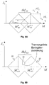
Im Allgemeinen sind die Gitterlinien des Basisgitters, welches ausgelegt ist, den Farbsaums des jeweiligen Basisglases mit der festgelegten Basiswirkung in einem vorgegebenen Bereich des Brillenglases zu minimieren, asymmetrische, geschlossene Kurven. Vorzugsweise verlaufen die Gitterlinien des Basisgitters im Wesentlichen senkrecht zur lokalen Achslage (Basislage) des Prismas des jeweiligen Basisglases.In general, the grid lines of the base grid, which is designed to minimize the color fringe of the respective base glass with the fixed basis effect in a predetermined area of the spectacle lens, are asymmetric, closed curves. Preferably, the grid lines of the base grid are substantially perpendicular to the local axis position (base position) of the prism of the respective base glass.
Vorzugsweise werden jedoch Basisgitter mit elliptischen Gitterlinien eingesetzt. Wie nachfolgend in Detail beschrieben wird, kann durch die Verwendung von Gittern mit elliptischen Gitterlinien mit einer minimalen Anzahl von Basisgittern eine optimale Farbsaumkorrektur auch für den Fall erzielt werden, dass der vorgegebene Wirkungsbereich ebenfalls zylindrische Wirkungen umfasst (d. h. für die Herstellung von sphärozylindrischen Brillengläsern).Preferably, however, basic grids are used with elliptical grid lines. As will be described in detail below, by using gratings having elliptical grating lines with a minimum number of base gratings, optimum color fringe correction can be achieved even in the case where the predetermined range of action also includes cylindrical effects (i.e., for the manufacture of sphero-cylindrical eyeglass lenses).
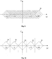
Alternativ können die Gitterlinien des jeweiligen Basisgitters rotationssymmetrisch sein. Es hat sich überaschenderweise herausgestellt, dass durch die Verwendung von Basisgittern mit rotationssymmetrischen (z. B. kreisförmigen) Gitterlinien, ebenfalls eine gute Farbsaumkorrektur auch bei nicht rotationssymmetrischen Brillengläsern erzielt werden kann.Alternatively, the grid lines of the respective base grid may be rotationally symmetric. Surprisingly, it has been found that by using basic gratings with rotationally symmetrical (eg circular) grid lines, a good color fringe correction can also be achieved even with non-rotationally symmetrical spectacle lenses.
Vorzugsweise ist der Abstand d(r) der Gitterlinien eines Basisgitters mit rotationssymmetrischen Gitterlinien variabel. Vorzugsweise ist der Abstand d(r) eine Funktion des radialen Abstands von der optischen oder geometrischen Mitte r: ![]()
![]()
Die optische Mitte des Brillenglases fällt bei nicht prismatischen Brillengläsern mit dem Prismenbezugspunkt zusammen. Bei prismatischen Brillengläsern liegt die optische Mitte in der Regel in einem Punkt, dessen Lage im Allgemeinen numerisch bestimmt werden kann, und welcher mit keinem besonderen, ausgezeichneten oder benannten Bezugspunkt im Brillenglas zusammen fallen muss. Näherungsweise ist die Position der optischen Mitte dadurch bestimmt, dass man die Gleichung für das Gesamtprisma, das sich nach der Prentice'schen Regel zu
Vorzugsweise wird der Abstand der Gitterlinien jedes der Basisgitter als Funktion des radialen Abstands d(r) von der optischen oder geometrischen Mitte nach der ![]()
Sref,0(λd) den refraktiven Anteil der dioptrischen Wirkung des Basisglases bei einer vorgegebenen Wellenlänge λd (Design-Wellenlänge);
Vd die Abbezahl der Basisgläser;
λF die F-Fraunhofer Linie, welche in die Definition der Abbezahl eingeht;
λC die C-Fraunhofer Linie, welche in die Definition der Abbezahl eingeht; und
m eine vorgegebene Beugungsordnung
bezeichnen.Preferably, the spacing of the grating lines of each of the base gratings is determined as a function of the radial distance d (r) from the optical or geometric center after ![]()
S ref, 0 (λ d) of the refractive component of the dioptric power of the base glass at a predetermined wavelength λ d (design wavelength);
V d the Abbe number of base glasses;
λ F the F-Fraunhofer line, which is included in the definition of the Abbe number;
λ C is the C-Fraunhofer lines, which enter into the definition of the Abbe number; and
m a predetermined diffraction order
describe.
Vorzugsweise umfasst der Wirkungsbereich astigmatische (zylindrische) Wirkungen mit einem maximalen Zylinder Zylmax. Das Festlegen der Basiswirkungen erfolgt vorzugsweise derart, dass für den maximalen Abstand |ΔM0G| der sphärischen Äquivalente der Basisgläser der Serie die Bedingung![]()
νd die Abbezahl der Basisgläser;
FST einen vorgegebenen Schwellwert;
2·rT den Durchmesser eines vorgegebenen Bereichs des jeweiligen Basisglases, in welchem der maximal zulässige Farbsaum kleiner oder gleich dem Schwellwert FST ist; und
Zylmax den maximal vorkommenden Astigmatismus in dem abzudeckenden Wirkungsbereich
bezeichnen.Preferably, the range of action comprises astigmatic (cylindrical) effects with a maximum cylinder Zyl max . The setting of the base effects is preferably carried out such that for the maximum distance | ΔM 0G | the spherical equivalents of the basic glasses of the series the condition ![]()
ν d is the Abbe number of base glasses;
FS T a predetermined threshold;
2 · r T is the diameter of a given area of the respective base glass, in which the maximum permissible color fringe is less than or equal to the threshold value FS T ; and
Zyl max the maximum occurring astigmatism in the coverage area
describe.
Es ist jedoch möglich, die Basiswirkungen lediglich anhand der abzudeckenden sphärischen Wirkung festzulegen. Vorzugsweise erfolgt das Festlegen der Basiswirkungen derart, dass für den maximalen Abstand |ΔM0G| der sphärischen Äquivalente der Basisgläser der Serie die Bedingung ![]()
νd die Abbezahl der Basisgläser;
FST einen vorgegebenen Schwellwert;
2·rT den Durchmesser eines vorgegebenen Bereichs des jeweiligen Basisglases, in welchem der maximal zulässige Farbsaum kleiner oder gleich dem Schwellwert FST ist;
bezeichnen.However, it is possible to determine the basic effects only by the spherical effect to be covered. Preferably, the base effects are set such that for the maximum distance | ΔM 0G | the spherical equivalents of the basic glasses of the series the condition ![]()
ν d is the Abbe number of base glasses;
FS T a predetermined threshold;
2 · T r the diameter of a predetermined range of the respective base glass in which the maximum allowable color fringing is less than or equal to the threshold T FS;
describe.
Der Schwellwert FST stellt eine Wahrnehmungsschwelle dar, unterhalb welcher der Farbsaum entweder nicht wahrgenommen oder als nicht störend empfunden wird.The threshold value FS T represents a perception threshold below which the color fringe is either not perceived or perceived as disturbing.
Jedem der Basisgläser der Serie kann jeweils einen Korrekturbereich zugeordnet werden, wobei das Basisgitter des Basisglases in dem jeweiligen Korrekturbereich den Farbsaum eines Brillenglases mit einer Wirkung innerhalb dieses Korrekturbereichs derart korrigiert, dass der Farbsaum des Brillenglases innerhalb eines vorgegeben Bereichs des Brillenglases kleiner oder gleich einem vorgegebenen Schwellwert ist. Der vorgegebene Schwellwert entspricht vorzugsweise einer Wahrnehmungsschwelle für den Farbsaum. Die Basiswirkungen können derart festgelegt werden, dass die Korrekturbereiche der einzelnen Basisgläser den vorgegebenen Wirkungsbereich abdecken.Each of the base glasses of the series can each be assigned a correction range, wherein the base grating of the base glass in the respective correction region corrects the fringe of a spectacle lens with an effect within this correction range such that the fringe of the spectacle lens within a predetermined region of the spectacle lens is less than or equal to a predefined one Threshold is. The predetermined threshold value preferably corresponds to a perception threshold for the color fringe. The basic effects can be determined in such a way that the correction ranges of the individual base glasses cover the given range of effectiveness.
Die Korrekturbereiche, d. h. die einzelnen Wirkungsbereiche, welche den einzelnen Basisgläsern zugeordnet werden, sind vorzugsweise um die jeweilige Basiswirkung zentriert. Besonders bevorzugt werden die Basisgitter so gewählt, dass durch Überlappung der Korrekturbereiche der einzelnen Basisgläser der ganze angestrebte Wirkungsbereich in Bezug auf die sphärische Wirkung oder das sphärische Äquivalent überdeckt wird. Anders ausgedrückt grenzen die Korrekturbereiche, welche den einzelnen Basisgläsern der Serie zugeordnet sind, vorzugsweise aneinander an, so dass innerhalb des gesamten abzudeckenden Wirkungsbereichs eine Reduktion des Farbsaums innerhalb des vorgegebenen Bereichs des Brillenglases unterhalb des vorgegeben Schwellwerts mit einer beschränkten Anzahl von Basisgittern erzielt werden kann.The correction areas, d. H. the individual areas of action, which are assigned to the individual base glasses, are preferably centered around the respective basic effect. Particularly preferably, the base grids are selected so that overlaps the correction ranges of the individual base glasses of the entire desired range of action in terms of the spherical effect or the spherical equivalent is covered. In other words, the correction areas assigned to the individual base glasses of the series preferably adjoin one another, so that a reduction of the color fringe within the predetermined area of the spectacle lens below the predetermined threshold with a limited number of base gratings can be achieved within the entire coverage area.
Es ist jedoch insbesondere bei sphärozylindrischen oder progressiven Brillengläsern möglich, dass die einzelnen Korrekturbereiche der Basisgläser nicht miteinander überlappen oder nicht aneinander angrenzen. Dabei wird in Kauf genommen, dass für bestimmte Wirkungen, z. B. bei hohen Zylindern, welche statistisch selten vorkommen, eine sub-optimale Korrektur des Farbsaums erzielt wird. Dieser Nachteil wird jedoch durch die Vorteile bei der Fertigung der Basisgläser im Wesentlichen ausgeglichen.However, it is possible in particular with sphero-cylindrical or progressive spectacle lenses that the individual correction areas of the base glasses do not overlap one another or do not adjoin one another. It is accepted that for certain effects, such. B. at high cylinders, which are statistically rare, a sub-optimal correction of the color fringes is achieved. However, this disadvantage is substantially offset by the advantages in the manufacture of the base glasses.
Der Bereich, innerhalb dessen der maximale Farbsaum kleiner oder gleich dem vorgegebenen Schwellwert ist, ist vorzugsweise ein kreisförmiger oder elliptischer Bereich um die geometrische Mitte, um den optischen Mittelpunkt, um den Scheitel des Brillenglases oder um einen anderen geeigneten Bezugspunkt. Der optische Mittelpunkt fällt z. B. mit dem Prismenbezugspunkt oder mit dem Zentrier- oder Anpaßpunkt des Brillenglases zusammen.The range within which the maximum color fringe is less than or equal to the predetermined threshold is preferably a circular or elliptical area about the geometric center, about the optical center, about the apex of the spectacle lens, or about another suitable reference point. The optical center falls z. B. together with the prism reference point or with the centering or fitting point of the lens.
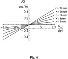
Vorzugsweise weist der vorgegebene Bereich des Brillenglases, innerhalb dessen der maximale Farbsaum kleiner oder gleich dem vorgegeben Schwellwert ist, einen Durchmesser von zumindest 40 mm auf. Vorzugsweise ist der vorgegebene Schwellwert 0,5 cm/m, vorzugsweise 0,4 cm/m, und besonders bevorzugt 0,12 cm/m.Preferably, the predetermined region of the spectacle lens, within which the maximum color fringing is less than or equal to the predetermined threshold, has a diameter of at least 40 mm. Preferably, the predetermined threshold is 0.5 cm / m, preferably 0.4 cm / m, and more preferably 0.12 cm / m.
Vorzugsweise umfasst der abzudeckende Wirkungsbereich sphärische Wirkungen von –12 dpt bis +12 dpt und/oder zylindrische Wirkungen bis 4 dpt, vorzugsweise bis 6 dpt.Preferably, the range of coverage to be covered comprises spherical effects of -12 dpt to +12 dpt and / or cylindrical effects up to 4 dpt, preferably to 6 dpt.
Das Verfahren kann ferner ein Aufbringen der so berechneten Basisgitter auf zumindest eine der refraktiven Flächen (Vorder-, Rückfläche oder eine andere Grenzfläche) des Basisglases umfassen. Das Basisglas kann z. B. ein herkömmlicher Blank oder ein Halbfabrikat sein. Ebenfalls ist es möglich, dass das Basisglas ein Compound-System umfassend zumindest ein Grundglas und ein Deckglas ist. Verfahren zum Aufbringen eines diffraktiven Gitters auf einer Fläche bzw. Herstellen eines diffraktiven Gitters sind aus dem Stand der Technik bekannt.The method may further include applying the base gratings thus calculated to at least one of the refractive surfaces (front, back surface or other interface) of the base glass. The base glass can z. B. be a conventional blank or a semi-finished product. It is also possible that the base glass is a compound system comprising at least a base glass and a cover glass. Methods for applying a diffractive grating to a surface or producing a diffractive grating are known from the prior art.
Ein weiterer Aspekt der Erfindung betrifft eine Vorrichtung zum Herstellen einer Serie von Basisgläsern, welche einen vorgegebenen Wirkungsbereich abdecken, wobei jedes Basisglas der Serie eine von den Basiswirkungen der anderen Basisgläser der Serie unterschiedliche Basiswirkung hat, und zumindest ein diffraktives Basisgitter aufweist, wobei die Vorrichtung derart ausgelegt ist, ein bevorzugtes Verfahren zum Herstellen einer Serie von Basisgläsern durchzuführen. Insbesondere umfasst die Vorrichtung zum Herstellen einer Serie von Basisgläsern Basisgitter-Berechnungsmittel, welche ausgelegt sind, das Basisgitter jedes der Brillengläser der Serie zu berechnen, wobei das Berechnen ein Festlegen der Basiswirkungen eines jeden Basisglases der Serie umfasst und derart erfolgt, den Farbsaums des jeweiligen Basisglases mit der festgelegten Basiswirkung in einem vorgegebenen Bereich des Brillenglases zu minimieren.A further aspect of the invention relates to a device for producing a series of base glasses which cover a predetermined range of effectiveness, wherein each base glass of the series has a base effect different from the base effects of the other base glasses of the series, and has at least one diffractive base grating, the device being such is designed to perform a preferred method for producing a series of base glasses. In particular, the apparatus for producing a series of base glasses comprises basic lattice computing means configured to calculate the base lattice of each of the lenses of the series, wherein the calculating comprises determining the basis effects of each base glass of the series and thus, the color fringe of the respective base glass to minimize with the specified basic effect in a given area of the spectacle lens.
Gemäß einem dritten Aspekt der Erfindung wird eine Serie von Basisgläsern umfassend zumindest zwei Basisgläser vorgeschlagen, wobei
jedes Basisglas der Serie eine von den Basiswirkungen der anderen Basisgläser der Serie unterschiedliche Basiswirkung hat und zumindest ein diffraktives Basisgitter aufweist, welches derart ausgelegt ist, dass der maximale Farbsaum innerhalb eines vorgegebenen Bereichs des Basisglases mit einem Durchmesser von zumindest 40 mm gleich oder kleiner als ein vorgegebener Schwellwert von 0,5 cm/m ist. According to a third aspect of the invention, a series of base glasses comprising at least two base glasses is proposed, wherein
each basic glass of the series has a base action different from the base effects of the other base glasses of the series and has at least one diffractive base grating configured such that the maximum color fringe within a predetermined range of the base glass having a diameter of at least 40 mm is equal to or smaller than one predetermined threshold value of 0.5 cm / m.
Das diffraktive Gitter kann ein zuvor beschriebenes diffraktives Gitter sein. Insbesondere kann das diffraktive Gitter auf der Vorderfläche oder auf der Rückfläche des Basisglases aufgebracht werden. Es ist auch möglich, diffraktive Gitter sowohl auf der Vorder- als auch auf der Rückfläche des Brillenglases aufzubringen. Ebenfalls ist es möglich, das diffraktive Gitter auf eine andere Grenzfläche des Basisglases aufzubringen, z. B. auf zumindest einer Grenzfläche im Inneren eines Compound-Systems.The diffractive grating may be a previously described diffractive grating. In particular, the diffractive grating can be applied on the front surface or on the back surface of the base glass. It is also possible to apply diffractive gratings both on the front and on the back surface of the spectacle lens. It is also possible to apply the diffractive grating to another interface of the base glass, for. B. on at least one interface in the interior of a compound system.
Das diffraktive Gitter eines jeden Basisglases kann derart für die Wirkung des Basisglases ausgelegt werden, dass eine optimale Korrektur des Farbsaums des Basisglases erzielt wird. Bei einer Abweichung der Wirkung des Brillenglases innerhalb des dem halbfertigen Brillenglas zugeordneten Wirkungsbereichs ist der Farbsaum dennoch innerhalb der vorgegebenen Grenzen. Anders ausgedrückt liegt der Farbsaum innerhalb des vorgegebenen Bereichs des Brillenglases unterhalb der vorgegebenen Schwelle. Wie bereits oben ausgeführt, ist der Bereich, innerhalb dessen der maximale Farbsaum kleiner oder gleich dem vorgegebenen Schwellwert ist, vorzugsweise ein kreisförmiger oder elliptischer Bereich um die geometrische Mitte, um den optischen Mittelpunkt, um den Scheitel des Brillenglases oder um einen anderen geeigneten Bezugspunkt.The diffractive grating of each base glass can be designed for the action of the base glass such that an optimal correction of the color fringes of the base glass is achieved. In the case of a deviation of the effect of the spectacle lens within the effective range associated with the semifinished spectacle lens, the fringing color is nevertheless within the prescribed limits. In other words, the color fringe is within the predetermined range of the spectacle lens below the predetermined threshold. As stated above, the range within which the maximum color fringe is less than or equal to the predetermined threshold is preferably a circular or elliptical area about the geometric center, about the optical center, about the vertex of the spectacle lens, or about another suitable reference point.
Vorzugsweise ist der maximale Farbsaum innerhalb des vorgegebenen Bereichs des Brillenglases kleiner oder gleich 0,4 cm/m, und besonders bevorzugt kleiner oder gleich 0,12 cm/m.Preferably, the maximum color fringe within the predetermined range of the spectacle lens is less than or equal to 0.4 cm / m, and particularly preferably less than or equal to 0.12 cm / m.
Vorzugsweise ist jedem der Basisgläser der Serie jeweils ein Korrekturbereich derart zugeordnet, dass für ein Brillenglas mit einer Wirkung innerhalb dieses Korrekturbereichs und mit dem gleichen Gitter, wie das Basisgitter des diesem Wirkungsbereich zugordneten Basisglases, der Farbsaum innerhalb des vorgegeben Bereichs des Brillenglases unter dem vorgegebenen Schwellwert liegt. Der Wirkungsabstand der Basisgläser der Serie ist vorzugsweise derart ausgelegt, dass die Korrekturbereiche der einzelnen Basisgläser einen vorgegebenen Wirkungsbereich abdecken.Preferably, each of the base glasses of the series is in each case assigned a correction range such that for a spectacle lens with an effect within this correction range and with the same grating as the base grating of the base glass assigned to this effective range, the color fringe within the predetermined range of the spectacle lens is below the predetermined threshold value lies. The effective distance of the base glasses of the series is preferably designed such that the correction regions of the individual base glasses cover a predetermined range of action.
Vorzugsweise umfasst der Wirkungsbereich, welcher durch die einzelnen Korrekturbereiche abgedeckt wird, sphärische Wirkungen von –12 dpt bis +12 dpt und/oder zylindrische Wirkungen bis 4 dpt, vorzugsweise bis zu 6 dpt.Preferably, the range of action covered by the individual correction areas includes spherical effects of -12 D to +12 D and / or cylindrical effects of up to 4 D, preferably up to 6 D.
Die Anzahl der Basisgläser ist vorzugsweise zwischen 5 und 20.The number of base glasses is preferably between 5 and 20.
Gemäß einer bevorzugten Ausführungsform umfasst der Wirkungsbereich, welcher durch die einzelnen Basisgläser der Serie abgedeckt wird, den Bereich sphärischer Wirkungen von –12 dpt bis +12 dpt. Wenn der maximale Farbsaum innerhalb eines zentralen Bereichs des Brillenglases mit einem Durchmesser von 40 mm beispielsweise unter 0,12 cm/m liegen soll (d. h. unterhalb der Wahrnehmungsschwelle) und die Abbezahl des Brillenglases νd = 42,41 ist, reichen lediglich 5 unterschiedliche Basisgitter und entsprechend 5 unterschiedliche Basisgläser aus, um den gesamten Wirkungsbereich abzudecken, da die einzelnen Korrekturbereiche ungefähr 5 dpt (d. h. ±2,5 dpt um die jeweilige sphärische Basiswirkung) betragen.According to a preferred embodiment, the range of action covered by the individual base glasses of the series covers the range of spherical effects from -12 dpt to +12 dpt. For example, if the maximum color fringing within a central region of the 40 mm diameter lens is below 0.12 cm / m (ie, below the perception threshold) and the Abbe number of the eyeglass lens is ν d = 42.41, then only 5 different base gratings are sufficient and correspondingly 5 different base glasses to cover the full range of effectiveness since the individual correction areas are approximately 5 D (ie ± 2.5 D about the respective basic spherical effect).
Wenn zusätzlich zu der sphärischen Wirkung auch eine zylindrische Wirkung mit einem maximalen Astigmatismus von 4 dpt abgedeckt werden soll, können in diesem Beispiel die Korrekturbereiche eine Breite von ungefähr 1 dpt (d. h. ±0,5 dpt um die jeweilige Basiswirkung) betragen. Der gesamte Wirkungsbereich mit einem betragsmäßig stärksten Hauptschnitt zwischen –12 dpt und +12 dpt kann folglich mit 20 unterschiedlichen Basisgittern bzw. 20 unterschiedlichen Basisgläsern abgedeckt werden. Wenn im Fall von sphärozylindrischen Gläsern zugelassen wird, dass für bestimmte Wirkungskombinationen keine vollständige Farbkorrektur stattfindet, kann auch bei sphärozylindrischen Gläsern die Anzahl unterschiedlicher Basisgitter und dementsprechend Basisgläser auf bis zu 5 reduziert werden.If, in addition to the spherical effect, a cylindrical effect with a maximum astigmatism of 4 dpt is to be covered, in this example the correction regions may be a width of approximately 1 dpt (i.e., ± 0.5 dpt around the respective base effect). The entire area of impact with a major section between -12 D and +12 D can be covered with 20 different basic lattices or 20 different base glasses. If, in the case of sphero-cylindrical glasses, complete color correction is not allowed for certain combinations of effects, the number of different basic lattices, and accordingly base glasses, can be reduced to as low as 5, even for spherocylindrical lenses.
Die Basisgläser können Einstärkengläser, Mehrstärkengläser oder Progressivgläser sein. Vorzugsweise sind die Basisgläser rotationssymmetrische Einstärkengläser, d. h. Einstärkengläser mit rotationssymmetrischen (z. B. sphärischen) Flächen.The basic glasses can be single-vision, multi-intensity or progressive lenses. Preferably, the base glasses are rotationally symmetrical single vision glasses, d. H. Single-vision lenses with rotationally symmetrical (eg spherical) surfaces.
Wie bereits oben ausgeführt, kann das diffraktive Gitter auf der Vorderfläche und/oder auf der Rückfläche von jedem der Basisgläser aufgebracht werden. Das Basisglas kann ein sogenanntes „Compound-System” sein, welches zumindest ein Grundglas und ein Deckglas umfasst. Das diffraktive Gitter kann auf zumindest einer Grenzfläche im Inneren des Compound-Systems aufgebracht werden. As stated above, the diffractive grating may be applied to the front surface and / or the back surface of each of the base glasses. The base glass may be a so-called "compound system" comprising at least a base glass and a cover glass. The diffractive grating can be applied to at least one interface in the interior of the compound system.
Das Basisgitter kann ein diffraktives Gitter mit elliptisch verlaufenden Gitterlinien sein. Alternativ kann das Basisgitter ein Gitter mit rotationssymmetrisch verlaufenden Gitterlinien sein. Vorzugsweise sind die Gitterlinien im Wesentlichen kreisförmig. Vorzugsweise ist der Abstand d(r) der Gitterlinien eines Basisgitters mit rotationssymmetrischen Gitterlinien variabel, insbesondere eine Funktion des radialen Abstands von der optischen oder geometrischen Mitte r: ![]()
![]()
Vorzugsweise gilt für den Abstand der Gitterlinien d(r) von der optischen Mitte des jeweiligen Basisglases: ![]()
Sref,0(λd) den refraktiven Anteil der dioptrischen Wirkung des Basisglases bei einer Wellenlänge λd;
νd die Abbezahl der Basisgläser;
λF die F-Fraunhofer Linie, welche in die Definition der Abbezahl eingeht;
λC die C-Fraunhofer Linie, welche in die Definition der Abbezahl eingeht; und
m, m = ±1, ±2, ... die Beugungsordnung
bezeichnen.Preferably, the distance of the grating lines d (r) from the optical center of the respective base glass is as follows: ![]()
S ref, 0 (λ d ) the refractive portion of the dioptric power of the base glass at a wavelength λ d ;
ν d is the Abbe number of base glasses;
λ F the F-Fraunhofer line, which is included in the definition of the Abbe number;
λ C the C-Fraunhofer line, which enters into the definition of Abbezahl; and
m, m = ± 1, ± 2, ... the diffraction order
describe.
Alle Basisgläser sind aus dem gleichen Material und weisen die gleiche Abbezahl auf. Die Beugungsordnung, für welche eine Korrektur stattfinden soll, wird vorgegeben. So kann z. B. ist m = –1 sein.All base glasses are made of the same material and have the same Abbe number. The diffraction order for which a correction is to take place is specified. So z. For example, m = -1.
Das Basisgitter kann ferner ein Gitter sein, dessen Gitterlinien im Wesentlichen senkrecht zu der lokalen Achslage (Basislage) des Prismas des jeweiligen Basisglases verlaufen.The base grid may further be a grid, the grid lines of which extend substantially perpendicular to the local axis position (base position) of the prism of the respective base glass.
Vorzugsweise erfüllt der maximal vorkommende Abstand |ΔMOG| der sphärischen Äquivalente der Basisgläser der Serie die Bedingung ![]()
![]()
νd die Abbezahl der Basisgläser;
FST den vorgegebenen Schwellwert;
2·rT den Durchmesser des vorgegebenen Bereichs;
Zylmax den maximal vorkommenden Astigmatismus
bezeichnen.Preferably, the maximum occurring distance | ΔM OG | the spherical equivalents of the basic glasses of the series the condition ![]()
![]()
ν d is the Abbe number of base glasses;
FS T the predetermined threshold value;
2 · r T is the diameter of the given area;
Cyl max the maximum occurring astigmatism
describe.
Die Gitterstrukturen der einzelnen Basisgitter können statisch sein. Es ist jedoch ebenfalls möglich, dass die Gitterstrukturen der einzelnen Basisgitter durch schaltbare Strukturen zu verwirklichen. Anders ausgedrückt können die einzelnen Basisgitter schaltbare, z. B. elektrisch schaltbare diffraktive Gitter sein. Schaltbare Gitter und insbesondere elektrisch schaltbare Gitter sind aus dem Stand der Technik bekannt. The lattice structures of the individual basic lattices can be static. However, it is also possible to realize the lattice structures of the individual basic lattices by means of switchable structures. In other words, the individual base grid switchable, z. B. be electrically switchable diffractive grating. Switchable grids and in particular electrically switchable grids are known from the prior art.
Ein beispielhaftes Verfahren zum Herstellen eines Brillenglases kann die folgenden Schritte umfassen:
Erfassen von Rezeptdaten des Brillenglases;
Bestimmen der Sollwirkung des Brillenglases in zumindest einem vorgegebenen Bezugspunkt des Brillenglases in Abhängigkeit von den erfassten Rezeptdaten;
Auswahl eines diffraktiven Gitters aus einem Satz von Basisgittern umfassend zumindest zwei unterschiedliche Basisgitter, wobei die Auswahl in Abhängigkeit von der Sollwirkung des Brillenglases in dem zumindest einen Bezugspunkt oder in Abhängigkeit von den erfassten Rezeptdaten erfolgt;
Fertigstellen eines Brillenglases mit dem ausgewählten Gitter derart, dass die Wirkung des fertiggestellten Brillenglases in dem zumindest einen Bezugspunkt im Wesentlichen gleich der zuvor bestimmten Sollwirkung in diesem Bezugspunkt ist, wobei
die einzelnen Basisgitter des Satzes für jeweils unterschiedliche Basiswirkungen derart ausgelegt sind, dass der maximale Farbsaum eines Brillenglases mit der jeweiligen Basiswirkung innerhalb eines vorgegebenen Bereichs des Brillenglases unter einer vorgegebenen Schwelle liegt.An exemplary method for producing a spectacle lens may include the following steps:
Acquisition of prescription data of the spectacle lens;
Determining the desired action of the spectacle lens in at least one predetermined reference point of the spectacle lens as a function of the acquired recipe data;
Selecting a diffractive grating from a set of base grids comprising at least two different base gratings, the selection taking place in dependence on the desired action of the spectacle lens in the at least one reference point or in dependence on the recorded recipe data;
Completing a spectacle lens with the selected grating so that the effect of the finished spectacle lens in the at least one reference point is substantially equal to the previously determined desired action in that reference point, wherein
the individual base gratings of the set are designed in each case for different base effects in such a way that the maximum color fringe of a spectacle lens with the respective basic action lies within a predetermined range of the spectacle lens below a predetermined threshold.
Gemäß einem Aspekt der Erfindung umfasst ein Verfahren zum Herstellen eines Brillenglases die Schritte
Erfassen von Rezeptdaten eines Brillenträgers, wobei die Rezeptdaten zumindest eine sphärische Rezeptwirkung umfassen;
Bestimmen der Sollwirkung des Brillenglases in zumindest einem vorgegebenen Bezugspunkt des Brillenglases in Abhängigkeit von den erfassten Rezeptdaten;
Auswahl eines Basisglases aus einer Serie von Basisgläsern mit den Merkmalen gemäß einem bevorzugten Beispiel der Erfindung in Abhängigkeit von den erfassten Rezeptdaten oder von der Sollwirkung des Brillenglases;
Bearbeiten des Basisglases derart, dass die Wirkung des fertigbearbeiteten Brillenglas in dem zumindest einen Bezugspunkt im Wesentlichen gleich der zuvor bestimmten Sollwirkung in diesem Bezugspunkt ist.According to one aspect of the invention, a method of manufacturing a spectacle lens comprises the steps
Acquiring prescription data of a spectacle wearer, the prescription data comprising at least one spherical prescription effect;
Determining the desired action of the spectacle lens in at least one predetermined reference point of the spectacle lens as a function of the acquired recipe data;
Selecting a base glass from a series of base glasses having the features according to a preferred example of the invention as a function of the acquired recipe data or of the desired action of the spectacle lens;
Processing the base glass such that the effect of the finished spectacle lens in the at least one reference point is substantially equal to the predetermined target effect in this reference point.
Insbesondere werden in Analogie zu einem herkömmlichen Basiskurvensystem den einzelnen Basisgläsern Teilwirkungsbereiche zugeordnet, wobei die einzelnen Teilwirkungsbereiche den vorgegebenen Wirkungsbereich abdecken. In Abhängigkeit von den erfassten Rezeptdaten oder von der Sollwirkung des Brillenglases wird dann ein Basisglas ausgewählt, dessen Teilwirkungsbereich den erfassten Rezeptdaten (insbesondere der sphärischen Rezeptwirkung) oder der Sollwirkung des Brillenglases in dem zumindest einen vorgegebenen Punkt entspricht.In particular, partial action ranges are assigned to the individual base glasses in analogy to a conventional base curve system, wherein the individual partial action ranges cover the predetermined range of action. Depending on the recorded recipe data or on the desired action of the spectacle lens, a base glass is then selected whose partial action range corresponds to the acquired recipe data (in particular the spherical prescription effect) or the desired action of the spectacle lens in the at least one predetermined point.
Insbesondere erfolgt die Auswahl in Analogie zu der Auswahl eines Halbfabrikats oder eines Blanks aus einem herkömmlichen Basiskurvensystem in Abhängigkeit von der sphärischen und gegebenenfalls der astigmatischen Rezeptwirkung oder in Abhängigkeit von der sphärischen Sollwirkung und gegebenenfalls der astigmatischen Sollwirkung, welches das fertige Brillenglas in zumindest einem vorgegebenen Bezugspunkt aufweisen soll. Die Sollwirkung kann sich von der Rezeptwirkung unterscheiden.In particular, the selection is carried out in analogy to the selection of a semi-finished product or a blanks from a conventional base curve system depending on the spherical and possibly the astigmatic recipe effect or depending on the spherical desired effect and optionally the astigmatic target effect, which the finished spectacle lens in at least one predetermined reference point should have. The desired effect may differ from the recipe effect.
So kann die Auswahl anhand des Soll-sphärischen Äquivalents in dem zumindest einem Bezugspunkt des Brillenglases oder anhand des sphärischen Äquivalents der Rezeptwirkung erfolgen. Der zumindest eine Bezugspunkt kann z. B. ein Zentrier- bzw. Anpaßpunkt, ein Fernbezugspunkt, ein Prismenbezugspunkt oder ein Nahbezugspunkt des Brillenglases sein.Thus, the selection can be made on the basis of the nominal spherical equivalent in the at least one reference point of the spectacle lens or on the basis of the spherical equivalent of the prescription effect. The at least one reference point can, for. B. be a centering point, a distance reference point, a prism reference point or a near reference point of the spectacle lens.
Das zumindest eine diffraktive Basisgitter kann auf einer ersten Fläche des Basisglases aufgebracht oder angeordnet sein. Die zweite Fläche des Brillenglases kann in an sich bekannter Weise in Abhängigkeit von den erfassten Rezeptdaten ermittelt bzw. berechnet werden. Das Bearbeiten des Basisglases umfasst dann das Bearbeiten der so ermittelten zweiten, gegenüber liegenden Fläche des Basisglases. Das Bearbeiten kann wie bei einem herkömmlichen Brillenglas, z. B. mittels NC-Maschinen, erfolgen.The at least one diffractive base grating can be applied or arranged on a first surface of the base glass. The second surface of the spectacle lens can be determined or calculated in a manner known per se as a function of the recorded recipe data. The processing of the base glass then includes the processing of the thus determined second, opposite surface of the base glass. The editing can as a conventional lens, z. B. by NC machines done.
Die zweite Fläche des Brillenglases kann mittels eines Optimierungsverfahrens ermittelt bzw. berechnet werden. Dementsprechend kann das Verfahren ferner ein Optimieren der zweiten Fläche des Brillenglases umfassen, wobei das Optimieren derart erfolgt, Abbildungsfehler zumindest zweiter Ordnung in Gebrauchsstellung des Brillenglases zu minimieren. Das Optimieren kann in Gebrauchsstellung des Brillenglases erfolgen, wobei die Abbildungsfehler zweiter Ordnung mittels einer Wellenfrontdurchrechnung unter Berücksichtigung des Basisgitters und der Gebrauchsstellung des Brillenglases ermittelt werden. Vorzugsweise erfolgt die Optimierung mittels einer Minimierung einer monochromatischen Zielfunktion oder einer polychromatischen Zielfunktion, in welcher der Farbsaum unmittelbar oder mittelbar durch die Berücksichtigung einer Wellenlängenabhängigkeit eingeht. Es hat sich herausgestellt, dass es möglich ist, durch eine nachträgliche Optimierung einer der refraktiven Flächen des Brillenglases die Abbildungsfehler zweiter oder gegebenenfalls höherer Ordnung zu reduzieren, ohne dass dabei die Farbsaumkorrektur wesentlich beeinträchtigt wird.The second surface of the spectacle lens can be determined or calculated by means of an optimization method. Accordingly, the method may further comprise optimizing the second surface of the spectacle lens, the optimization being carried out in such a way as to minimize aberrations of at least second order in the position of use of the spectacle lens. The optimization can be carried out in the position of use of the spectacle lens, wherein the aberrations of the second order by means of a wavefront analysis under Considering the base grid and the position of use of the spectacle lens can be determined. Preferably, the optimization is carried out by means of a minimization of a monochromatic objective function or a polychromatic objective function, in which the fringing is received directly or indirectly by the consideration of a wavelength dependence. It has been found that it is possible, by subsequent optimization of one of the refractive surfaces of the spectacle lens, to reduce the aberrations of the second or possibly higher order without substantially impairing the color fringe correction.
Nach dem obigen Verfahren kann eine Serie von (farbsaumkorrigierten) Brillengläsern mit unterschiedlichen Wirkungen hergestellt werden, welche einen gesamten Wirkungsbereich abdecken, wobei der maximale Farbsaum jedes der Brillengläser der Serie innerhalb eines vorgegebenen Bereichs mit einem vorgegebenen Bereich kleiner oder gleich einem vorgegebenen Schwellwert von 0,5 cm/m, vorzugsweise kleiner oder gleich 0,4 cm/m ist, und besonders bevorzugt kleiner oder gleich 0,12 cm/m ist.According to the above method, a series of (color fringe-corrected) spectacle lenses having different effects covering an entire range of effect can be produced, wherein the maximum fringe of each of the spectacle lenses of the series is within a predetermined range with a predetermined range less than or equal to a predetermined threshold of 0, 5 cm / m, preferably less than or equal to 0.4 cm / m, and more preferably less than or equal to 0.12 cm / m.
Der Wirkungsbereich kann sphärische Wirkungen von zumindest –12 dpt bis +12 dpt und/oder zylindrische Wirkungen bis 4 dpt, vorzugsweise bis zu 6 dpt umfassen. Der vorgegebene Bereich kann z. B. ein Bereich mit einem Durchmesser von mindestens 40 mm sein.The range of effect may include spherical effects of at least -12 D to +12 D and / or cylindrical effects up to 4 D, preferably up to 6 D. The predetermined range can z. B. be an area with a diameter of at least 40 mm.
Gemäß einem weiteren Aspekt der Erfindung wird eine Vorrichtung zum Herstellen eines Brillenglases vorgeschlagen, welche ausgelegt ist, das Verfahren zum Herstellen eines Brillenglases auszuführen. Die Vorrichtung kann insbesondere aufweisen:
Erfassungsmittel zum Erfassen von Rezeptdaten eines Brillenträgers, wobei die Rezeptdaten zumindest eine sphärische Rezeptwirkung umfassen;
Sollwirkungs-Berechnungsmittel zum Bestimmen der Sollwirkung des Brillenglases in zumindest einem vorgegebenen Bezugspunkt des Brillenglases in Abhängigkeit von den erfassten Rezeptdaten;
Auswahlmittel zur Auswahl eines Basisglases aus einer Serie von Basisgläsern gemäß einem bevorzugten Beispiel der Erfindung in Abhängigkeit von den erfassten Rezeptdaten oder von der Sollwirkung des Brillenglases;
Bearbeitungsmittel zum Bearbeiten des Basisglases derart, dass die Wirkung des fertigbearbeiteten Brillenglas in dem zumindest einen Bezugspunkt im Wesentlichen gleich der zuvor bestimmten Sollwirkung in diesem Bezugspunkt ist.According to a further aspect of the invention, an apparatus for producing a spectacle lens is proposed, which is designed to carry out the method for producing a spectacle lens. The device may in particular comprise:
Detecting means for acquiring prescription data of a spectacle wearer, the prescription data comprising at least a spherical prescription effect;
Desired-effect calculation means for determining the desired action of the spectacle lens in at least one predetermined reference point of the spectacle lens in dependence on the acquired recipe data;
Selection means for selecting a base glass from a series of base glasses according to a preferred example of the invention as a function of the detected recipe data or the desired action of the spectacle lens;
Processing means for processing the base glass such that the effect of the finished spectacle lens in the at least one reference point is substantially equal to the predetermined target effect in this reference point.
Gemäß einem weiteren Aspekt der Erfindung wird eine Serie von Brillengläsern mit unterschiedlichen Wirkungen, welche einen Wirkungsbereich von zumindest –12 dpt bis +12 dpt der sphärischen Wirkung abdecken, vorgeschlagen. Die Serie ist jedoch nicht auf den Wirkungsbereich von –12 dpt bis +12 dpt beschränkt, sondern kann einen kleinere oder einen größeren Wirkungsbereich abdecken. Jedes Brillenglas der Serie weist zumindest ein diffraktives Gitter auf. Die Anzahl der unterschiedlichen Gitter aller Brillengläser der Serie ist kleiner als die Anzahl der Brillengläser. Der maximale Farbsaum jedes der Brillengläser der Serie innerhalb eines vorgegebenen Bereichs mit einem Durchmesser von zumindest 40 mm kleiner oder gleich einem vorgegebenen Schwellwert von 0,5 cm/m ist. Vorzugsweise ist der maximale Farbsaum innerhalb des vorgegebenen Bereichs des Brillenglases kleiner oder gleich 0,4 cm/m, und besonders bevorzugt kleiner oder gleich 0,12 cm/m.According to a further aspect of the invention, a series of spectacle lenses with different effects covering an effective range of at least -12 D to +12 D of the spherical effect is proposed. However, the series is not limited to the range of -12 D to +12 D, but can cover a smaller or larger range of impact. Each spectacle lens of the series has at least one diffractive grating. The number of different grids of all spectacle lenses of the series is smaller than the number of spectacle lenses. The maximum color fringe of each of the spectacle lenses of the series within a predetermined range with a diameter of at least 40 mm is less than or equal to a predetermined threshold value of 0.5 cm / m. Preferably, the maximum color fringe within the predetermined range of the spectacle lens is less than or equal to 0.4 cm / m, and particularly preferably less than or equal to 0.12 cm / m.
Der Wirkungsabstand zwischen zwei benachbarten Wirkungen bzw. die Abstufung der Wirkungen der Brillengläser der Serie kann z. B. 0,5 dpt sein, vorzugsweise 0,25 dpt. Der Abstand kann auch kleiner als 0,25 dpt sein, z. B. 0,125 dpt.The effective distance between two adjacent effects or the gradation of the effects of the spectacle lenses of the series can, for. B. 0.5 dpt, preferably 0.25 dpt. The distance may also be less than 0.25 D, z. B. 0.125 dpt.
Der vorgegebene Wirkungsbereich kann ferner zylindrische Wirkungen bis 4 dpt, vorzugsweise bis zum 6 dpt, umfassen. Der Abstand zwischen zwei benachbarten sphärozylindrischen Wirkungen kann z. B. 0,5 dpt sein. Vorzugsweise ist der Abstand zwischen zwei benachbarten sphärozylindrischen. Wirkungen 0,25 dpt. Der Abstand kann auch kleiner als 0,25 dpt sein, z. B. 0,125 dpt.The predetermined range of action may also include cylindrical effects up to 4 dpt, preferably up to 6 dpt. The distance between two adjacent spherocylindrical effects can e.g. B. be 0.5 dpt. Preferably, the distance between two adjacent spherocylindrical. Effects 0.25 dpt. The distance may also be less than 0.25 D, z. B. 0.125 dpt.
Vorzugsweise ist die Anzahl der unterschiedlichen Gitter in der Serie zwischen 5 und 20.Preferably, the number of different gratings in the series is between 5 and 20.
Die Brillengläser können Einstärkengläser, Mehrstärkengläser oder Progressivgläser sein.The spectacle lenses can be single vision lenses, multifocal lenses or progressive lenses.
Das zumindest eine diffraktive Gitter jedes Brillenglases der Serie kann auf der Vorderfläche und/oder auf der Rückfläche und/oder auf einer anderen Grenzfläche des Brillenglases aufgebracht werden. Die Grenzfläche kann – wie oben beschrieben – eine Grenzfläche im Inneren eines Compound-Systems umfassend ein Grundglas und ein Deckglas sein.The at least one diffractive grating of each spectacle lens of the series can be applied to the front surface and / or on the rear surface and / or on another interface of the spectacle lens. As described above, the interface may be an interface inside a compound system comprising a base glass and a cover glass.
Die beschränkte Anzahl von unterschiedlichen Gittern, welche die Brillengläser der Serie aufweisen, werden für eine beschränkte Anzahl von Brillengläsern (Basisgläsern) mit vorgegebenen, unterschiedlichen Basiswirkungen berechnet oder optimiert. Vorzugsweise werden die einzelnen Gitter derart berechnet oder optimiert, den Farbsaum des jeweiligen Basisglases mit der vorgegebenen Basiswirkung zu minimieren. Im Allgemeinen sind die Gitterlinien der einzelnen Gitter asphärische Kurven. The limited number of different gratings comprising the spectacle lenses of the series are calculated or optimized for a limited number of spectacle lenses (base glasses) with predetermined, different base effects. Preferably, the individual gratings are calculated or optimized in such a way as to minimize the color fringe of the respective base glass with the predetermined basic effect. In general, the grid lines of the individual gratings are aspherical curves.
Vorzugsweise verlaufen die Gitterlinien der einzelnen Gitter elliptisch. Alternativ können die Gitterlinien rotationssymmetrisch, z. B. im Wesentlichen kreisförmig verlaufen. Vorzugsweise ist der Abstand d(r) der Gitterlinien eines Basisgitters mit rotationssymmetrischen Gitterlinien variabel, insbesondere eine Funktion des radialen Abstands von der optischen oder geometrischen Mitte r: 
Für den Gitterabstand als Funktion des radialen Abstands d(r) von der optischen Mitte des Brillenglases gilt vorzugsweise: ![]()
Sref,0(λd) den refraktiven Anteil der dioptrischen Wirkung des entsprechenden Basisglases bei einer Wellenlänge λd;
νd die Abbezahl der Basisgläser;
λF die F-Fraunhofer Linie, welche in die Definition der Abbezahl eingeht;
λC die C-Fraunhofer Linie, welche in die Definition der Abbezahl eingeht; und
m, m = ±1, ±2, .... die Beugungsordnung
bezeichnen.For the lattice spacing as a function of the radial distance d (r) from the optical center of the spectacle lens, the following applies preferably: ![]()
S ref, 0 (λ d ) the refractive portion of the dioptric power of the corresponding base glass at a wavelength λ d ;
ν d is the Abbe number of base glasses;
λ F the F-Fraunhofer line, which is included in the definition of the Abbe number;
λ C the C-Fraunhofer line, which enters into the definition of Abbezahl; and
m, m = ± 1, ± 2, .... the diffraction order
describe.
Die Gitterstrukturen der einzelnen Gitter können statisch sein. Alternativ können die Gitterstrukturen der einzelnen Gitter durch insbesondere elektrisch schaltbare Strukturen verwirklicht werden.The lattice structures of the individual lattices can be static. Alternatively, the grating structures of the individual grids can be realized by in particular electrically switchable structures.
Ein weiterer Aspekt der Erfindung betrifft ein progressives Brillenglas mit zumindest einem rotationsymmetrischen oder elliptischen diffraktiven Gitter, wobei der maximale Farbsaum des progressiven Brillenglases innerhalb eines im Wesentlichen kreisförmigen Bereichs des progressiven Brillenglases mit einem Durchmesser von d ≤ 40 mm kleiner oder gleich 0,5 cm/m ist, vorzugsweise kleiner oder gleich 0,4 cm/m ist, und besonders bevorzugt kleiner oder gleich 0,12 cm/m ist.A further aspect of the invention relates to a progressive spectacle lens having at least one rotationally symmetrical or elliptic diffractive grating, wherein the maximum color fringe of the progressive spectacle lens within a substantially circular region of the progressive spectacle lens with a diameter of d ≤ 40 mm is less than or equal to 0.5 cm / m is preferably less than or equal to 0.4 cm / m, and more preferably less than or equal to 0.12 cm / m.
Ferner betrifft ein weiterer Aspekt der Erfindung ein astigmatisches Brillenglas mit zumindest einem rotationsymmetrischen oder elliptischen Gitter, wobei der maximale Farbsaum des progressiven Brillenglases innerhalb eines im Wesentlichen kreisförmigen Bereichs des progressiven Brillenglases mit einem Durchmesser von d ≤ 40 mm kleiner oder gleich 0,5 cm/m ist, vorzugsweise kleiner oder gleich 0,4 ist, und besonders bevorzugt kleiner oder gleich 0,12 cm/m ist.Furthermore, a further aspect of the invention relates to an astigmatic spectacle lens having at least one rotationally symmetrical or elliptical grating, the maximum chromatic aberration of the progressive spectacle lens within a substantially circular region of the progressive spectacle lens having a diameter of d≤40 mm being less than or equal to 0.5 cm / m is preferably less than or equal to 0.4, and more preferably less than or equal to 0.12 cm / m.
Vorzugsweise ist in beiden Fällen das Gitter rotationssymmetrisch, wobei der Abstand der Gitterlinien variabel ist. Vorzugsweise ist der variable Abstand der Gitterlinien eine Funktion des radialen Abstands von der optischen oder geometrischen Mitte r: ![]()
![]()
Vorzugsweise gilt für den Abstand der Gitterlinien d(r) von der optischen Mitte ![]()
Sref,0(λd) den refraktiven Anteil der dioptrischen Wirkung eines vorgegebenen Basisglases mit einer vorgegebenen Basiswirkung bei einer Wellenlänge λd;
νd die Abbezahl des Brillenglases;
λF die F-Fraunhofer Linie, welche in die Definition der Abbezahl eingeht;
λC die C-Fraunhofer Linie, welche in die Definition der Abbezahl eingeht; und
m, m = ±1, ±2, ... eine vorgegebene Beugungsordnung
bezeichnen. Preferably, the spacing of the grating lines d (r) from the optical center applies ![]()
S ref, 0 (λ d) of the refractive component of the dioptric power of a given base glass having a predetermined base effect at a wavelength λ d;
ν d is the Abbe number of the spectacle lens;
λ F the F-Fraunhofer line, which is included in the definition of the Abbe number;
λ C the C-Fraunhofer line, which enters into the definition of Abbezahl; and
m, m = ± 1, ± 2, ... a given diffraction order
describe.
Weiteren Aufgaben, Merkmale und Vorteile der vorliegenden Erfindung werden aus der nachfolgenden Beschreibung beispielhafter Ausführungsformen mit Bezug auf die Zeichnungen ersichtlich. Es zeigen:Other objects, features and advantages of the present invention will become apparent from the following description of exemplary embodiments with reference to the drawings. Show it:
Ein Hauptmerkmal eines diffraktiven Gitters ist dabei der Beugungsfaktor, der beschreibt, dass die Intensitätsverteilung mehrere Maxima enthält, die sich nach den Beugungsordnungen m durchzählen lassen. Diese folgen einem modifizierten Brechungsgesetz n'sinφ' – nsinφ = mλ/d. Lediglich das Maximum der 0-ten Beugungsordnung (m = 0) genügt dem klassischen Brechungsgesetz. Alle anderen Richtungen kämen refraktiv nicht vor. Im Strahlenbild bedeutet dies, dass ein Strahl in mehrere Teilstrahlen aufgespaltet wird. Wie sich die Intensität auf die einzelnen Beugungsordnungen aufteilt, wird durch den Formfaktor bestimmt.
Bei der Übertragung dieser Grundsachverhalte auf optische Elemente (z. B. Prismen, Linsen, Brillengläser, etc.) muss berücksichtigt werden, dass ein optisches Element zumindest zwei Grenzflächen besitzt. Dabei ist es üblich
- 1) Polarisationseffekte zu vernachlässigen, d. h. mit der skalaren Beugungstherorie weiterhin auszukommen,
- 2) das Rayleigh-Sommerfeldsche Beugungsintegral mit Fraunhofer- oder höchstens Fresnel-Beugung zu betrachten,
- 3) nur Fernfeldinterferenzen zu betrachten und
- 4) Streuungseffekte zu vernachlässigen.
- 1) to neglect polarization effects, ie to continue to get along with the scalar diffraction theory,
- 2) to consider the Rayleigh-Sommerfeld diffraction integral with Fraunhofer or at most Fresnel diffraction,
- 3) only to consider far-field interferences and
- 4) neglect scattering effects.
Die dritte Annahme wird oft stillschweigend getroffen. Diese ist jedoch gültig, solange die beiden Glasflächen weiter voneinander entfernt sind als die Kohärenzlänge von Tageslicht oder Glühlampenlicht von 3. Dies ist in der Regel bei Brillengläsern der Fall.The third assumption is often tacitly made. However, this is valid as long as the two glass surfaces are farther apart than the coherence length of daylight or incandescent light of 3. This is usually the case with spectacle lenses.
Der Farbsaum von optischen Elementen im Allgemeinen beruht darauf, dass diese zumindest zwei refraktive Grenzflächen aufweisen, wobei die beiden kombinierten refraktiven Grenzflächen eines optischen Elements eine wellenlängenabhängige prismatische Wirkung Prref besitzen. Die Anwendung von diffraktiver Optik zur Farbsaumkorrektur basiert darauf, auf zumindest einer der refraktiven Grenzflächen des optischen Elements ein diffraktives Gitter aufzubringen, für das aufgrund des diffraktiv modifizierten Brechungsgesetzes für m ≠ 0 eine zusätzliche prismatische Wirkung Prdiff eingeführt wird.The color fringe of optical elements in general is based on having at least two refractive interfaces, wherein the two combined refractive interfaces of an optical element have a wavelength-dependent prismatic effect Pr ref . The use of diffractive optics for color fringe correction is based on applying a diffractive grating to at least one of the refractive interfaces of the optical element, for which an additional prismatic effect Pr diff is introduced for m ≠ 0 due to the diffractive modified refractive law.
Bei geeigneter Auslegung oder Dimensionierung des diffraktiven Gitters (insbesondere der Periode d des diffraktiven Gitters) gibt es dann eine Ordnung m = m0, für welche die Wellenlängenabhängigkeit von Prdiff der gewöhnlichen Dispersion des refraktiven Prismas Prref entgegengesetzt ist und ein derartige Größe hat, dass das Gesamtprisma Pr = Prref + Prdiff nahezu wellenlängenunabhängig ist. Um genau für diese Ordnung m0 eine möglichst hohe Intensität zu erreichen, d. h. um die Beugungseffizienz zu maximieren, kann die Gitterform geeignet gestaltet werden. Bei einem Sägezahngitter erfolgt dies durch eine geeignete Wahl des Blazing-Winkels.Given a suitable design or dimensioning of the diffractive grating (in particular the period d of the diffractive grating), there is then an order m = m 0 for which the wavelength dependence of Pr diff is opposite to the usual dispersion of the refractive prism Pr ref and has such a size, the total prism Pr = Pr ref + Pr diff is almost wavelength independent. In order to achieve as high an intensity as possible for this order m 0 , ie in order to maximize the diffraction efficiency, the lattice shape can be designed appropriately. In a sawtooth this is done by a suitable choice of the blazing angle.
Farbsaum und optimale Farbsaumkompensation durch ein diffraktives Gitter bei einem refraktiven PrismaColor fringe and optimal color fringe compensation through a diffractive grating in a refractive prism
Wie bereits oben ausgeführt entsteht bei einem optischen Element (wie z. B. einer Linse, einem Prisma, einem Brillenglas, etc.), welches durch rein refraktive Flächen begrenzt ist, ein Farbsaum als Folge von zwei aufeinanderfolgenden Brechungen, bei denen jeweils kurzwelliges Licht stärker gebrochen wird als langwelliges. Der Farbsaum ist ein lokales Phänomen, das sich durch die kombinierte lokale prismatische Wirkung beider Einzelflächen gut beschreiben lässt, d. h. durch das Gesamtprisma, das durch die lokale Verkippung der beiden Flächen zueinander um einen Prismenkeilwinkel α entsteht.As already stated above, in the case of an optical element (such as a lens, a prism, a spectacle lens, etc.), which is delimited by purely refractive surfaces, a color fringe arises as a result of two successive refractions, in each case short-wave light is broken stronger than longwave. The color fringe is a local phenomenon, which can be well described by the combined local prismatic effect of both individual surfaces, ie by the total prism, which arises by the local tilting of the two surfaces to each other by a prism wedge angle α.
Anhand eines solchen Prismas kann auch die Auswirkung zusätzlicher diffraktiver Gitter beschrieben werden, die auf der Prismenvorderfläche (Fläche 1) oder der Prismenrückfläche (Fläche 2) oder auf beiden Flächen (nachfolgend auch Grenzflächen genannt) aufgebracht werden können.Such a prism can also be used to describe the effect of additional diffractive gratings which can be applied on the prism front surface (surface 1) or the prism rear surface (surface 2) or on both surfaces (also referred to as boundary surfaces hereinafter).
Für jedes Gitter, welches auf zumindest einer der Flächen 1 oder 2 aufgebracht ist, kann eine entsprechende Phasenfunktion Ψ1.2 eingeführt werden. Die Phasenfunktion
Der an einer der Grenzflächen einfallenden Wellenfront 


n'1 den Brechungsindex des Materials nach der Grenzfläche 1;
n1 den Brechungsindex des Materials vor der Grenzfläche 1;
n'2 den Brechungsindex des Materials nach der Grenzfläche 2;
n2 den Brechungsindex des Materials vor der Grenzfläche 2;
φ1 den Einfallswinkel des Strahls auf die Grenzfläche 1;
φ'1 den Austrittswinkels des Strahls nach der Brechung an der Grenzfläche 1;
φ2 den Einfallswinkel des Strahls auf die Grenzfläche 2;
φ'2 den Austrittswinkels des Strahls nach der Brechung an der Grenzfläche 2;
m1 und m2 die Beugungsordnungen
bezeichnen.The incident at one of the interfaces wavefront
n ' 1 the refractive index of the material after the
n 1 is the refractive index of the material in front of the
n ' 2 the refractive index of the material after the
n 2 is the refractive index of the material in front of the
φ 1 the angle of incidence of the beam on the
φ ' 1 is the exit angle of the beam after refraction at the
φ 2 the angle of incidence of the beam on the
φ '2 is the exit angle of the beam after refraction at the
m 1 and m 2 the diffraction orders
describe.
In einer ersten Annäherung eines optischen Elements mit einem diffraktiven Gitter kann die obige allgemeine Formel statt auf die Raumdimensionen x, y nur auf eine Raumdimension x angewendet werden (eindimensionaler Fall). Werden ferner nur diejenige Strahlen betrachtet, welche in der Ebene senkrecht zur Prismenkante verlaufen, dann ist es ausreichend, statt den Winkeln φx und φy einen Winkel φ zu verwenden.In a first approximation of an optical element having a diffractive grating, the above general formula can be applied to only one space dimension x (one-dimensional case) instead of the space dimensions x, y. Furthermore, if only those rays are considered which extend in the plane perpendicular to the prism edge, then it is sufficient to use an angle φ instead of the angles φ x and φ y .
An den (Grenz)Flächen 1 und 2 gilt dann entsprechend: 
In einer paraxialen Näherung gilt sinφ'1 ≈ φ'1, sinφ'2 ≈ φ'2 etc... Sind ferner die Grenzflächen 1 und 2 (z. B. die Grenzflächen eines Brillenglases) von Luft umgeben, dann gilt n1 = 1, n'1 = n, n2 = n, n'2 = 1, wobei n der Brechungsindex des optischen Materials zwischen den Grenzflächen ist.In a paraxial approximation, sinφ ' 1 ≈ φ' 1 , sinφ ' 2 ≈ φ' 2 etc ... Furthermore, if the

In diesem einfachen Fall kann Gleichung (1) auf den Lichtdurchgang durch ein Prisma mit einem lokalen Prismenkeilwinkel α(x) angewendet werden. Für die lokale wellenlängenabhängige Winkelablenkung gilt dann: 
Das bedeutet, dass die totale Winkeländerung additiv aus zwei Beiträgen zusammen setzt, nämlich aus einem refraktiven und einem diffraktiven Anteil: 
Dabei können Δφref(x; λ) als das refraktive Prisma oder das Grundprisma, Δφdiff(x; λ) als das diffraktive Prisma und Δφ(x; λ) als das Gesamtprisma bezeichnet werden.Therein, Δφ ref (x; λ) may be referred to as the refractive prism or the basic prism, Δφ diff (x; λ) as the diffractive prism, and Δ φ (x; λ) as the total prism.
Ein Maß für den Farbsaum FS eines optischen Elements (z. B. eines refraktiven Prismas, einer refraktiven Linse, eines Brillenglases, etc.) ist die absolute Winkelbreite des Farbsaums
Alternativ kann als Maß für den Farbsaum die absolute Winkelbreite
Nachfolgend wird als Maß für den Farbsaum die absolute Winkelbreite FS = |Δφ(x; λF) – Δφ(x; λC)| entsprechend der alternativen Abbezahl νd = (nd – 1)/(nF – nC) verwendet. Selbstverständlich können die nachfolgenden Formeln auch für den Fall entsprechend angewendet werden, dass der Farbsaum durch FS = |Δφ(x; λF') – Δφ(x; λC')| oder z. B. durch andere Wellenlängen definiert wird. In diesem Fall tritt an Stelle des Index d der Index e, anstelle des Index F der Index F', und anstelle des Index C der Index C'.Subsequently, as a measure of the color fringing the absolute angular width FS = | Δφ (x; λ F) - Δφ (x; λ C) | according to the alternative Abbe number ν d = (n d - 1) / (n F - n C ) used. Of course, the following formulas can also be applied accordingly for the case where the fringing color is given by FS = | Δφ (x; λ F ' ) - Δφ (x; λ C' ) | or z. B. is defined by other wavelengths. In this case, instead of the index d, the index e, instead of the index F, the index F ', and instead of the index C, the index C' occurs.
Es ist zweckmäßig, eine vorzeichenabhängige Definition des Farbsaums zu verwenden, z. B.
Der refraktive Farbsaum ist durch das Prisma, geteilt durch die Abbezahl gegeben: 
Der diffraktive Farbsaumbeitrag ist durch 
Damit eine ”ideale” Farbsaumkompensation des refraktiven Farbsaums durch den diffraktiven Beitrag stattfinden kann, muss gelten
Soll der Farbsaum für ein Prisma mit refraktiver prismatischer Wirkung Δφref = Δφref,0 vollständig korrigiert werden, dann muss das diffraktive Gitter so gewählt werden, dass 
![]()
![]()
Im Fall eines Prismas mit Planflächen und einer von x unabhängigen refraktiven Ablenkung Δφref,0(λd) eignet sich eine Phasenfunktion der Form Ψ(x; λ) = α1x + α0. Aus Gleichung (12) kann der Parameter α1 wie folgt bestimmt werden: ![]()
![]()
Da in diesem Fall die Bedingung![]()
![]()
![]()
![]()
Wird eine Farbsaumkorrektur passend zum Grundprisma Δφref,0 vorgenommen und ist das tatsächliche Grundprisma durch Δφref gegeben, dann kompensiert das Gitter den Farbsaum nur teilweise und der restliche Farbsaum ist gegeben durch 
Das gesamte Prisma bei Wellenlänge λd im Fall einer teilweisen Farbsaumkompensation ist durch 
Bei einer vollständigen Farbsaumkompensation ist die Bedingung Δφref(x; λd) = Δφref,0(x; λd) erfüllt. In diesem Fall ist FS(x) = 0 . Das gesamte Prisma bei Wellenlänge λd ist nach Gleichung (14) gegeben durch 
Da λF – λC < 0 ist, ist die Klammer größer als 1, so dass das Gesamtprisma Δφ gegenüber dem Grundprisma Δφref,0 immer leicht verstärkt ist.Since λ F - λ C <0, the clip is greater than 1, so that the overall prism Δφ respect to the base prism Δφ ref, is always slightly increased 0th
![]()

![]()
![]()
![]()
Farbsaum und (optimale) Farbsaumkompensation durch ein diffraktives Gitter bei einem rotationssymmetrischen EinstärkenglasColor fringe and (optimal) color fringe compensation by a diffractive grating in a rotationally symmetrical single-vision lens
Rotationssymmetrische Brillengläser können statt durch zwei unabhängige Koordinaten x und y durch einen einzigen Freiheitsgrad beschrieben werden. Wird dieser Freiheitsgrad mit r bezeichnet, dann können für die Meridionalstrahlen Gleichungen (1) bis (15) angewendet werden, indem dort x durch r ersetzt wird. Die Prentice'sche Regel besagt, dass Δφref(r; λd) = –Sref(λd)r ist. Hierbei steht Sref für die refraktive dioptrische Wirkung des Glases, die aufgrund der Flächenkrümmungen zustandekommt und r für den Abstand von der optischen Mitte oder dem Scheitel des Brillenglases. Unter ”Wirkung” des Glases kann auch der Scheitelbrechwert des Glases, der Brechwert, die Brechkraft oder ein sonstiges Maß für die Wirkung verstanden werden.Rotationally symmetrical spectacle lenses can be described by a single degree of freedom instead of by two independent coordinates x and y. If this degree of freedom is denoted by r, equations (1) to (15) can be used for the meridional rays by replacing x with r. Prentice's rule states that Δφ ref (r; λ d ) = -S ref (λ d ) r. Here, S ref stands for the refractive dioptric effect of the glass, which is due to the surface curvatures and r for the distance from the optical center or the vertex of the spectacle lens. "Effect" of the glass may also be understood to mean the vertex power of the glass, the refractive index, the refractive power or some other measure of the effect.
Der refraktive Farbsaum nach Gleichung (8) ist in diesem Fall 
Der diffraktive Farbsaum eines passend zur refraktiven Wirkung Sref,0 gewählten Gitters ist nach Gleichung (11) 
Der gesamte Farbsaum ergibt sich nach Gleichung (13) zu 
Der Farbsaum eines rotationssymmetrischen Einstärkenglases ist nach Gleichung (16) proportional zur Wirkung und zum Abstand r.The color fringe of a rotationally symmetrical single-vision lens is proportional to the effect and the distance r according to equation (16).
Eingezeichnet in
Wie aus der
Gleichung (18) bedeutet, dass der Farbsaum eines rotationssymmetrischen Glases mit einem diffraktiven Gitter von der Differenz (Sref – Sref,0) so abhängt, wie der Farbsaum eines unkorrigierten Glases von Sref allein. Eine Farbsaumkorrektur, welche passend zur Wirkung Sref,0 vorgenommen wird, bewirkt folglich lediglich eine Verschiebung des gemeinsamen Schnittpunktes aller Geraden, die sich in
Soll der Farbsaum für das Glas mit refraktiver Wirkung Sref(λd) = Sref,0(λd) vollständig korrigiert werden, dann muss das diffraktive Gitter so gewählt werden, dass Gleichung (17) erfüllt ist, d. h. dass die Bedingung 
Dies kann z. B. durch ein Gitter mit einer Phasenfunktion![]()
![]()
![]()
![]()
Wegen der Bedingung
![]()
![]()
Der diffraktive Beitrag zur Wirkung eines Gitters, das passend zur refraktiven Wirkung Sref,0(λd) gewählt ist, ergibt sich dann nach Gleichung (12) zu 
Die gesamte Wirkung eines teilweise farbsaumkompensierten Glases ist gemäß Gleichung (14) gegeben durch 
Die gesamte Wirkung bei vollständiger Farbsaumkompensation ist gemäß Gleichung (15) gegeben durch 
Da bei unvollständiger Farbsaumkompensation 
Der Farbsaum kann folglich als Funktion von S durch Abbildungen, die aus den
Maßgeblich dafür, inwieweit der Farbsaum in der Peripherie von rotationssymmetrischen Einstärkengläsern nicht vollständig korrigiert wird, ist folglich die Abweichung zwischen der verordneten sphärischen Gesamtwirkung und der Gesamtwirkung, an die das Gitter angepasst ist.The decisive factor for the extent to which the color fringe in the periphery of rotationally symmetrical single vision lenses is not completely corrected is consequently the deviation between the prescribed total spherical effect and the overall effect to which the grating is adapted.
Farbsaum und (optimale) Farbsaumkompensation durch ein diffraktives Gitter bei einem sphärozylindrischen Einstärkenglas Color fringe and (optimal) color fringe compensation by a diffractive grating in a spherocylindrical single-vision lens
Hat ein Einstärkenglas zusätzlich zu der Wirkung ebenfalls einen Zylinder, fehlt die Rotationssymmetrie. In diesem Fall werden zwei Freiheitsgrade x und y benötigt, die sich zu einem Vektor
Zur Definition des Farbsaums eines nicht rotationssymmetrischen Brillenglases kann die Gleichung (6) wie folgt modifiziert werden:
Falls ein Gitter passend zu einer anderen sphärozylindrischen Wirkung ist als zu der aktuell vorliegenden, kann eine Modifikation von Gleichung (18) zur Abschätzung des Farbsaums verwendet werden, bei welcher die Größen Sref, Sref,0 durch die Brechwertmatrizen
Die Brechwertmatrizen hängen wie folgt von den sphärozylindrischen (SZA-)Werten (Sphäre S, Zylinder Z, Achse A) der Wellenfront bzw. der Refraktion ab: 
In diesem Fall ergibt sich für den Farbsaum: 

Maßgeblich dafür, inwieweit der Farbsaum in der Peripherie von sphärozylindrischen Einstärkengläsern nicht vollständig korrigiert wird, ist folglich die durch eine Matrixdifferenz beschriebene Abweichung zwischen der verordneten sphärozylindrischen Gesamtwirkung und der sphärozylindrischen Gesamtwirkung, an die das Gitter angepasst ist. Diese Abweichung kommt durch
- – die Abweichung zwischen der verordneten sphärischen Gesamtwirkung und der sphärischen Gesamtwirkung, an die das Gitter angepasst ist; und
- – die Abweichung zwischen der verordneten zylindrischen Gesamtwirkung und der zylindrischen Gesamtwirkung, an die das Gitter angepasst ist zustande.
- - the deviation between the prescribed total spherical effect and the total spherical effect to which the lattice is fitted; and
- - the deviation between the prescribed overall cylindrical effect and the overall cylindrical effect to which the grid is adapted.
Farbsaum und (optimale) Farbsaumkompensation durch ein diffraktives Gitter bei einem ProgressivglasColor fringing and (optimal) color fringe compensation through a diffractive grating in a progressive glass
Um den Farbsaum eines Progressivglases durch ein diffraktives Gitter ideal zu kompensieren, ist es erforderlich, das Gitter individuell an den Wirkungsverlauf anzupassen. Dies kann beispielsweise durch eine simultane Optimierung von Brillenglasflächen und einem diffraktiven Gitter erfolgen. Alternativ kann dies durch die Wahl eines Gitters, dessen Gitterlinien im Wesentlichen senkrecht zur lokalen Achslage (Basislage) des Prismas des jeweiligen Brillenglases verlaufen, durchgeführt werden.In order to ideally compensate the color fringe of a progressive glass by means of a diffractive grating, it is necessary to adapt the grating individually to the course of the effect. This can be done for example by a simultaneous optimization of spectacle lens surfaces and a diffractive grating. Alternatively, this can be done by the choice of a grating whose grating lines are substantially perpendicular to the local axis position (base position) of the prism of the respective spectacle lens.
Die Optimierung erfolgt vorzugsweise in einer vorgegebenen Gebrauchsstellung des Basisglases. Die Gebrauchsstellung kann insbesondere durch den Fassungsscheibenwinkel, die Vorneigung, den Hornhautscheitelabstand, die Pupillendistanz, und gegebenenfalls weitere Parameter charakterisiert werden. Die Parameter der Gebrauchsstellung können durchschnittliche Parameter sein. Ebenfalls wird vorzugsweise ein vorgegebener Objektabstand (vorzugsweise als Funktion der Blickrichtung) berücksichtigt.The optimization is preferably carried out in a predetermined position of use of the base glass. The position of use can be characterized in particular by the frame disc angle, the preadjustment, the corneal vertex distance, the pupillary distance, and optionally further parameters. The parameters of the position of use can be average parameters. Also preferably a predetermined object distance (preferably as a function of the viewing direction) is taken into account.
Vorzugsweise erfolgt die Optimierung derart, Abbildungsfehler zumindest zweiter Ordnung zu minimieren. Die Optimierung kann eine Minimierung einer polychromatischen Zielfunktion umfassen, in welcher der Farbsaum unmittelbar oder mittelbar durch eine Wellenlängenabhängigkeit als Zielgröße eingeht. Die Abbildungsfehler zweiter oder höherer Ordnung werden vorzugsweise mittels einer Wellenfrontdurchrechnung unter Berücksichtigung des Basisgitters und der Gebrauchsstellung des Brillenglases ermittelt.The optimization is preferably carried out in such a way as to minimize aberrations of at least second order. The optimization may include minimizing a polychromatic objective function in which the fringe is received directly or indirectly by a wavelength dependence as a target. The aberrations of the second or higher order are preferably determined by means of a wavefront analysis, taking into account the basic grating and the position of use of the spectacle lens.
Für jedes Gitter, das nicht ideal angepasst ist, verbleibt ein restlicher Farbsaum, dessen Verteilung jedoch außer vom Gitter auch vom speziellen Brillenglasdesign des Progressivglases abhängt und daher nicht so pauschal wie für Einstärkengläser durch die Gleichungen (23) und (23a) beschrieben werden kann.For any grating that is not ideally matched, there remains a residual fringe, but apart from the grating, its distribution also depends on the particular lens design of the progressive lens and therefore can not be described as overall as for single vision lenses by equations (23) and (23a).
Auswahl eines BasisgittersystemsSelection of a basic grid system
Die obigen Angaben über die ideale Anpassung eines diffraktiven Gitters an ein Brillenglas legen die Vorstellung nahe, dass für jeden gegebenen Wirkungsverlauf ein individuell darauf abgestimmtes diffraktives Gitter auch tatsächlich benötigt wird. Eine solche Vorstellung wird insbesondere durch die Gleichungen (23) und (23a) nahegelegt, da laut diesen Gleichungen bereits der Farbsaum eines Einstärkenglases mit Wirkung S bzw.
Überaschenderweise hat sich jedoch herausgestellt, dass dies zur Erreichung einer als optimal empfundenen Farbsaumkorrektur nicht erforderlich ist. Stattdessen ist es ausreichend, nur für einige Basiswirkungen ein farbsaumkorrigierendes Gitter zu verwenden und dieses Gitter aber auch noch für benachbarte Wirkungen zuzulassen, solange diese so eng benachbart sind, dass der Farbsaum unter einer vorgegebenen Schwelle bleibt.Surprisingly, however, it has been found that this is not necessary to achieve a perceived optimal color fringe correction. Instead, it is sufficient to use a color fringe correcting grating for only a few basis effects and to allow this grating to be used for adjacent effects as long as they are so closely adjacent that the fringing remains below a predetermined threshold.
Rotationssymmetrische EinstärkengläserRotationally symmetrical single vision lenses
Ein beispielhaftes Verfahren zur Aufstellung eines Basisgittersystems für rotationssymmetrische Einstärkengläser lässt sich anhand von
Ferner wird der Radius rT eines Sehfeldes auf dem Brillenglas, vorzugsweise um die optische oder die geometrische Mitte (oder um einen anderen vorgegebenen Bezugspunkt) vorgegeben, innerhalb dessen (r ≤ rT) der Farbsaum unter der vorgegebenen Schwelle FST bleiben soll (d. h. innerhalb dessen |FS| ≤ FST gefordert wird). Bevorzugt ist der Wert rT = 20 mm. Jeder andere Wert rT kann jedoch gefordert werden.Furthermore, the radius r T of a visual field on the spectacle lens, preferably around the optical center or the geometric center (or at another predetermined reference point), within which (r ≤ r T ) the color fringe should remain below the predetermined threshold FS T (ie within which | FS | ≤ FS T is required). Preferably, the value r T = 20 mm. Any other value r T , however, may be required.
Gleichung (23) kann dann Auskunft darüber geben, wie hoch der Wert (S – S0) gerade noch sein darf, damit die Vorgaben |FS| ≤ FST innerhalb des Sehfeldes mit einem Radius rT nicht verletzt werden. Hierzu kann in der Gleichung (23) der Schwellwert FST eingesetzt und die Gleichung dann nach |S – S0| aufgelöst werden: 
Für die bevorzugten Zahlenwerte (FST ≤ 0,12 cm/m, rT = 20 mm) ergibt sich ![]()
![]()
Für rotationssymmetrische Einstärkengläser kann daher ein Basisgittersystem
Wie in 
Sphärozylindrische Einstärkengläser Spherocylindrical single-vision lenses
Fehlt wie bei Einstärkengläsern mit einer zylindrischen Verordnung die Rotationssymmetrie, so müssten die exakt farbsaumkorrigierenden Gitter ebenfalls ohne Rotationssymmetrie sein.If the rotational symmetry is missing, as in the case of single-vision glasses with a cylindrical regulation, then the exact color-space-correcting gratings would also have to be without rotational symmetry.
Es ist jedoch erkannt worden, dass eine als optimal empfundene Korrektur des Farbsaums ebenfalls anhand eines Satzes von rotationssymmetrischen Gittern erzielt werden kann. Gemäß einem bevorzugten Beispiel der Erfindung wird daher vorgeschlagen, statt einen Satz von asymmetrischen Basisgittern, einen Basisgittersatz BG von rotationssymmetrischen Basisgittern zu verwenden. Dabei wird in Kauf genommen, dass diese rotationssymmetrischen Gitter den Farbsaum in der Peripherie von sphärozylinderischen Einstärkengläsern nicht vollkommen korrigieren, sondern nur zu einem bestimmten Anteil. Der verbleibende Farbsaum kann durch die Anwendung der Gleichung (23a) bestimmt werden. Es ist jedoch ebenfalls möglich, einen Satz von nicht-sphärischen Gittern zu verwenden.However, it has been recognized that a perceived optimal correction of the color fringe can also be achieved on the basis of a set of rotationally symmetric gratings. According to a preferred example of the invention it is therefore proposed, instead of using a set of asymmetric base gratings, to use a basic lattice set B G of rotationally symmetric basic lattices. It is accepted that these rotationally symmetric grids do not completely correct the color fringe in the periphery of sphero-cylindrical single-vision lenses, but only to a certain extent. The remaining color fringe can be determined by the application of equation (23a). However, it is also possible to use a set of non-spherical lattices.
In Analogie zu der Aufstellung eines Basisgittersystems für rotationssymmetrische Einstärkengläser kann zur Aufstellung eines Basisgittersystems für sphärozylindrische Einstärkengläser allgemein verlangt werden, dass
Im Falle von Gleichung (23a) bedeutet dies, dass die Bedingung 
Dies ist sichergestellt, wenn für die beiden Eigenwerte von (
Die Matrizen 
M, J0, J45 sind die Komponenten des Powervektors 
M0, J0,0, J0,45 sind die Komponenten des Powervektors 
Der jeweilige Powervektor enthält die Summe aus dem refraktiven und dem diffraktiven Anteil der Wirkungen des Glases.The respective power vector contains the sum of the refractive and the diffractive parts of the effects of the glass.
Es gilt: 
Das Gebiet eines Power-Vektors


Für sphärozylindrische Einstärkengläser kann folglich ein Basisgittersystem
Sind die Basisgitter rein sphärisch, wie in einem bevorzugten. Beispiel, dann stellt sich ferner die Frage, wie stark diese überlappen müssen, damit ein bestimmter maximal vorkommender Zylinder Zylmax noch für alle relevant vorkommenden Werte des sphärischen Äquivalents abgedeckt werden können. Are the base lattices purely spherical, as in a preferred one. For example, the question then arises as to how much they must overlap so that a certain maximum occurring cylinder Zyl max can still be covered for all relevant values of the spherical equivalent.
In
Im Überlappungsbereich kommen für eine Farbsaumkorrektur beide Basisgitter in Frage. Eine bevorzugte Basisgitterzuordnung kann so getroffen werden, dass die Trennungslinie
Wie in 
Bei einem Vergleich der Gleichung (30) mit der Gleichung (26) kann festgestellt werden, dass eine dichtere Überdeckung erforderlich ist, wenn zylindrische Wirkungen mit abgedeckt werden sollen. Ist der maximale Zylinder durch Zylmax = 4,0 dpt gegeben, dann gilt statt Gleichung (27), dass
Die Abdeckung des gleichen Wirkungsbereichs mit wenigen Basisgittern kann dadurch erzielt werden, dass die Basisgitter selbst auch schon an zylindrische Basiswirkungen angepasst sind und somit nicht mehr rotationssymmetrisch sind. Die erforderlichen nicht rotationssymmetrischen Gitter können anhand der Überlappung durch Doppelkegel im Raum in Analogie zu dem obigen Fall von rotationssymmetrischen Gittern ermittelt werden.The coverage of the same area of action with a few basic gratings can be achieved by the fact that the basic grids themselves are already adapted to cylindrical base effects and are thus no longer rotationally symmetrical. The required non-rotationally symmetric gratings can be determined on the basis of the overlapping by double cones in space in analogy to the above case of rotationally symmetric gratings.
Vorzugsweise erfolgt jedoch die Überdeckung des Wirkungsbereichs durch rein rotationssymmetrische Gitter wie in
Eine andere Möglichkeit, ein Basisgittersystem mit noch weniger Basisgittern aufzustellen, besteht darin, Gleichung (19) nicht für alle sphärozylindrischen Gläser des Wirkungsbereichs eine Farbsaumkorrektur zu fordern, sondern nur für die rein sphärischen. In diesem Fall kann für vorhandene hohe Zylinder (z. B. Zylinder über 2 dpt) zugelassen werden, dass der Farbsaum auch innerhalb des Kreises mit Radius rT um die optische Mitte über der Schwelle FST liegen kann. Stattdessen kann sich das Basisgittersystem auf die statistisch überwiegenden niedrigen Zylinder konzentrieren.Another way to set up a basic lattice system with even fewer base lattices is to require equation (19) not a color fringe correction for all spherocylindrical glasses of the effective range, but only for the purely spherical ones. In this case, for existing high cylinders (eg cylinders over 2 D), it can be allowed that the fringe can also lie within the circle of radius r T about the optical center above the threshold FS T. Instead, the base grid system can focus on the statistically predominant low cylinders.
Progressivgläserprogressive lenses
Bei Progressivgläsern fehlt normalerweise jegliche Symmetrie. Überaschenderweise hat sich jedoch herausgestellt, dass wenn ein progressives Glas in seiner optischen Mitte ein bestimmtes sphärisches Äquivalent aufweist, ein zu diesem Wert passendes, um die optische Mitte rotationssymmetrisches diffraktives Gitter bewirkt, dass auch der Farbsaum außerhalb der optischen Mitte mehr oder weniger stark korrigiert wird.Progressive lenses normally lack any symmetry. Surprisingly, however, it has been found that if a progressive glass has a certain spherical equivalent in its optical center, a diffraction grating which is rotationally symmetric about the optical center causes the color fringe outside the optical center to be more or less corrected ,
Maßgeblich dafür, inwieweit der Farbsaum in der Peripherie von Progressivgläsern nicht vollständig korrigiert wird, ist dabei die durch eine Matrixdifferenz beschriebene Abweichung zwischen der verordneten sphärozylindrischen Gesamtwirkung und der sphärozylindrischen Gesamtwirkung, an die das Gitter angepasst ist. Diese kommt zustande durch
- – die Abweichung zwischen der verordneten sphärischen Gesamtwirkung und der sphärischen Gesamtwirkung, an die das Gitter angepasst ist und
- – die Abweichung zwischen der verordneten zylindrischen Gesamtwirkung und der zylindrischen Gesamtwirkung, an die das Gitter angepasst ist, sowie
- – die Abweichung des lokalen Prismas von demjenigen, das das dem Gitter zugrundeliegende Glas hätte, aufgrund des Wirkungshubs und aufgrund des peripheren Astigmatismus des Progressivglases.
- The deviation between the prescribed total spherical effect and the total spherical effect to which the lattice is fitted and
- - the deviation between the prescribed overall cylindrical effect and the overall cylindrical effect to which the grille is fitted, and
- The deviation of the local prism from that which would have the glass underlying the grating, due to the action and due to the peripheral astigmatism of the progressive glass.
Anders als bei sphärozylindrischen Einstärkengläsern hängt eine allgemeine Vorschrift für die Aufstellung eines minimalen Basisgittersystems, welches verträglich mit einer Forderung wie in Gleichung (19) ist, von den Einzelheiten des Brillenglasdesigns ab. Gemäß einem bevorzugten Beispiel der Erfindung wird jedoch ein Basisgittersystem vorgeschlagen, welches wie in
Eine andere mögliche Basisgitterzuordnung kann sich nach dem sphärischen Äquivalent der Rezeptwirkung richten, das nicht notwendig gleich dem sphärischen Äquivalent des Glases in der optischen Mitte ist, außer in dem Fall, dass die optische Mitte zufällig in dem Zentrierpunkt BZ liegt.Another possible base grating assignment may be based on the spherical equivalent of the prescription effect, which is not necessarily equal to the spherical equivalent of the glass in the optical center except in the case where the optical center happens to be in the center point B Z.
Die so ermittelten Basisgitter können jeweils auf eine der Flächen (Vorder-, Rückfläche oder sonstige Grenzfläche) von Basisgläsern mit den Basiswirkungen S0 aufgebracht werden. Der Satz von Basisgläsern mit den Basisgittern kann als vorgefertigter Satz von halbfertigen Basisgläsern vorliegen. Bei der Herstellung von Brillengläsern, welche an die Rezeptdaten eines Brillenträgers angepasst werden sollen, kann ein geeignetes halbfertiges Basisglas ausgewählt werden und die der Fläche mit dem Basisgitter gegenüberliegende Fläche in Abhängigkeit von den Rezeptdaten des Brillenträgers bearbeitet werden.The base gratings determined in this way can each be applied to one of the surfaces (front, rear surface or other boundary surface) of base glasses having the basic effects S 0 . The set of base glasses with the base lattices may be present as a prefabricated set of semi-finished base glasses. In the manufacture of spectacle lenses, which are to be adapted to the prescription data of a spectacle wearer, a suitable semi-finished base glass can be selected and the surface opposite the surface with the base grating can be processed in dependence on the prescription data of the spectacle wearer.
Nachfolgend wird das Berechnen eines optimalen Basisgitters für ein bestimmtes Basisglas mit einer vorgegebenen Basiswirkung mittels einer Optimierung beschrieben:
Das Ermitteln eines diffraktiven Gitters, welches zur Korrektur des Farbsaums eines vorgegebenen Brillenglases dient, kann z. B. in folgenden Schritten erfolgen:
- 1) Modellbildung im wellenoptischen Bild;
- 2) Aus der wellenoptischen Intensitätsverteilung wird eine bestimmte Ordnung selektiert. Die Gitterkonstante wird so gewählt, dass der „Peak” dieser Ordnung wellenlängenunabhängig ist. Dadurch wird eine Farbsaumkorrektur ermöglicht. Die Form des Gitters (z. B. der Blazing-Winkel bei einem Sägezahngitter) wird so eingestellt, dass die Beugungseffizienz für diese Ordnung maximal ist. Schließlich wird die Ausfallsrichtung für diesen Peak durch einen Strahl beschrieben (geometrisches Strahlenbild, ray-tracing)
- 3) Simultane Optimierung des Gitters und der refraktiven Fläche, wobei die Abbildungseigenschaften zweier und höherer Ordnung des Brillenglases mit dem Gitter berücksichtigt werden. Gemäß einem Aspekt der Erfindung wird ein Übergang zu geometrischen Wellenfronten und wave-tracing vorgeschlagen, um die Abbildungseigenschaften des Brillenglases (vorzugsweise in Gebrauchsstellung) zu berechnen und gegebenenfalls zu optimieren.
The determination of a diffractive grating, which is used to correct the color fringe of a given spectacle lens, can, for. B. in the following steps:
- 1) modeling in the wave-optical image;
- 2) From the wave-optical intensity distribution a certain order is selected. The lattice constant is chosen so that the "peak" of this order is wavelength independent. This allows a color fringe correction. The shape of the grid (eg, the blazing angle in a sawtooth grid) is set so that the diffraction efficiency for this order is maximum. Finally, the direction of failure for this peak is described by a ray (geometric ray pattern, ray-tracing)
- 3) Simultaneous optimization of the grating and the refractive surface, taking into account the imaging properties of two and higher order of the spectacle lens with the grating. According to one aspect of the invention, a transition to geometric wavefronts and wave-tracing is proposed in order to calculate and if necessary to optimize the imaging properties of the spectacle lens (preferably in the position of use).
Die ersten zwei Schritte sind nicht auf ein Optimierungsverfahren beschränkt und können auch unabhängig von dem dritten Schritt erfolgen.The first two steps are not limited to an optimization procedure and can be done independently of the third step.
Modellbildung im wellenoptischen Bild. Modeling in the wave-optical image.
Eine zentrale Größe der Wellenoptik ist die Verteilung von Amplitude und Phase. Durch die Berechnung des Beugungsintegrals kann die Aufspaltung in Form- und Beugungsfaktor reproduziert werden. Unabhängig davon, wie sich die Beugungsordnungen später zur Farbsaumkorrektur nutzen lassen, ist es vorteilhaft, dass die Intensität möglichst nur in einer einzigen Ordnung gesammelt wird. So kann z. B. mit Hilfe eines Sägezahngitters mit einem bestimmten Blazing-Winkel erreicht werden, dass zumindest bei einer definierten bzw. vorgegebenen Designwellenlänge praktisch eine Beugungseffizienz von ungefähr 100% für die gewählte Beugungsordnung erreicht werden kann.
Der Formfaktor ist eine relativ breite Glockenfunktion, die genau entlang derjenigen Richtung zentriert ist, die aufgrund der Steigung der Flächenabschnitte im Gitter auch schon nach dem klassischen Brechungsgesetz die Ausfallsrichtung wäre. Je nach Profil des Gitters (z. B. je nach Blazing-Winkel) kann diese Richtung nun auf ein Beugungsmaximum einer gewünschten Beugungsordnung verschoben werden (siehe
FarbsaumkorrekturFarbsaumkorrektur
Wenn kein diffraktives Gitter vorhanden ist, wird die Intensitätsverteilung durch eine Kurve gegeben, deren Maximum durch die Kurve „F” des Formfaktors in
Bei Anwesenheit eines diffraktiven Sägezahngitters ändert sich daran nichts, außer dass die Breite des Formfaktor-Peaks nun um Größenordnungen zunimmt und durch den Einfachspalt bestimmt wird, der nun durch eine Gitterperiode gegeben ist (siehe Kurve „F” in
Variiert nun die Wellenlänge, dann wandert der Formfaktor langsam über diesen konstanten Peak, mit nur geringen Verlusten an Beugungseffizienz, hinweg (siehe
Geometrisches Strahlenbild und Farbsaumkorrektur.Geometric ray image and color fringe correction.
Wir bereits oben ausgeführt können durch eine geeignete Wahl des Profils des diffraktiven Gitters alle Beugungsmaxima zugunsten eines einzigen außer Acht gelassen werden. Die Ausfallsrichtung des verbliebenen Beugungsmaximus kann im geometrischen Strahlenbild durch das modifizierte Brechungsgesetz n'sinφ' – nsinφ = mλ/d beschrieben werden.As already stated above, by a suitable choice of the profile of the diffractive grating, all diffraction maxima in favor of a single one can be disregarded. The failure direction of the remaining diffraction maximum can be described in the geometric ray image by the modified law of refraction n'sinφ '- nsinφ = mλ / d.
Für eine Farbsaumkorrektur eines (lokalen) Prismas wird verlangt, dass die prismatische Ablenkung eines Strahls, welcher durch beide Grenzflächen des Prismas fällt und durch das Prisma abgelenkt wird, für eine vorgegebene Wellenlänge (Designwellenlänge) wellenlängenunabhängig ist. Die Wellenlängenunabhängigkeit ist im Sinne einer verschwindenden Ableitung nach der Wellenlänge zu verstehen.For a color fringe correction of a (local) prism, it is required that the prismatic deflection of a beam which passes through both prism boundary surfaces and is deflected by the prism be wavelength independent for a given wavelength (design wavelength). The wavelength independence is to be understood in terms of a vanishing derivative according to the wavelength.
Anhand dieser Bedingung kann dann die Gitterkonstante d ermittelt werden, welche proportional zur Abbezahl und der Beugungsordnung und umgekehrt proportional zum Prisma ist. Überaschenderweise hat sich herausgestellt, dass der so ermittelte Wert der Gitterkonstante nicht, wie erwartet, in der Größenordnung der Wellenlänge, sondern z. B. für ein Prisma von 4 cm/m und bei einer Abbezahl νd ≈ 40 bei einem Wert von über d ≈ 100 μm liegt. Dies kann damit erklärt werden, dass nicht eine Brechkraft, sondern nur der geringere Effekt der Farbsaumkorrektur erreicht werden soll.On the basis of this condition, the lattice constant d can then be determined, which is proportional to the Abbezahl and the diffraction order and inversely proportional to the prism. Surprisingly, it has been found that the value of the lattice constant thus determined is not, as expected, in the order of the wavelength, but z. B. for a prism of 4 cm / m and at a Abbe number ν d ≈ 40 at a value of about d ≈ 100 microns. This can be explained by the fact that not a refractive power, but only the lower effect of the color fringe correction is to be achieved.
Wie oben gezeigt wurde, ist diejenige Beugungsordnung, für welche Farbsaumkorrektur eintritt, immer so gerichtet, dass eine Verstärkung des ursprünglichen Prismas eintritt. Das Gesamtprisma Pr = Prref + Prdiff liegt dabei im Betrag immer um ca. 5% bis 10% über dem Betrag |Prref| des rein refraktiven Anteils. As shown above, the diffraction order for which color fringe correction occurs is always directed so that enhancement of the original prism occurs. The total prism Pr = Pr ref + Pr diff is always about 5% to 10% higher than the amount | Pr ref | of the purely refractive component.
Soll statt an einem Prisma der Farbsaum an einer Linse (z. B. an einem Brillenglas) korrigiert werden, können die Ergebnisse der Farbsaumkorrektur mittels eines Prismas auf die Farbsaumkorrektur einer Linse übertragen werden, indem der Wert von d lokal so einstellt wird, dass er das lokale Prisma korrigiert. Im Allgemeinen ist das so ermittelte Gitter jedoch nicht mehr äquidistant (d. h. weist keine äquidistanten Gitterlinien auf). Für Linsen (z. B. Brillengläser) variiert jedoch die nun variable Funktion d(r) so langsam, dass die Modellvorstellung der Periodizität, die zur Herleitung der wellenoptischen Gleichungen verwendet wurde, näherungsweise gültig bleibt.If the color fringe on a lens (eg on a spectacle lens) is to be corrected instead of on a prism, the results of color fringe correction can be transmitted to the fringe correction of a lens by means of a prism by locally adjusting the value of d corrected the local prism. In general, however, the grating so determined is no longer equidistant (i.e., does not have equidistant grating lines). For lenses (eg, spectacle lenses), however, the now variable function d (r) varies so slowly that the model of the periodicity used to derive the wave-optical equations remains approximately valid.
Da das lokale Prisma nach der Prentice'schen Regel proportional zu r ist, kann die Periode d(r) eines Gitters, welches den Farbsaum eines Brillenglases korrigieren soll, umgekehrt proportional zu r gewählt werden, d. h. d(r) = A/r. Die Konstante A ist dabei proportional zur Abbezahl und der Beugungsordnung und umgekehrt proportional zum Scheitelbrechwert. Analog zum Prisma wird wegen der Prentice'schen Regel auch der Betrag des Scheitelbrechwerts durch den diffraktiven Beitrag um 5% bis 10% erhöht.Since the local prism is proportional to r according to Prentice's rule, the period d (r) of a lattice which is to correct the color fringe of a spectacle lens can be chosen to be inversely proportional to r, i. H. d (r) = A / r. The constant A is proportional to the Abbezahl and the diffraction order and inversely proportional to the vertex power. Similarly to the prism, due to the Prentice rule, the value of the vertex power is increased by 5% to 10% due to the diffractive contribution.
Bei der obigen Betrachtung wird jedoch die tatsächliche Gebrauchsstellung der Linse nicht berücksichtigt. Insbesondere wird nicht berücksichtigt, dass das Prisma in Gebrauchsstellung der Linse von dem nach der Prentice'schen Regel ermittelten Prisma abweichen kann. Im Allgemeinen ist daher die Abhängigkeit der Periode von r komplexer. Die Periode d(r) kann daher in Form eines Potenzreihenansatzes mit Termen proportional zu r2, r, 1, 1/r, 1/r2, ... dargestellt werden. Vorzugsweise werden die Koeffizienten der einzelnen Terme durch eine simultane Optimierung von Gitter und refraktiver Fläche ermittelt. Es hat sich jedoch herausgestellt, dass in vielen Fällen, auch bei einer vollständigen Durchrechnung, der 1/r-Term die anderen Termen so stark dominiert, dass diese Terme praktisch vernachlässigt werden können.In the above consideration, however, the actual position of use of the lens is not considered. In particular, it is not considered that the prism in the position of use of the lens can deviate from the prism determined according to Prentice's rule. In general, therefore, the dependence of the period of r is more complex. The period d (r) can therefore be represented in the form of a power series approach with terms proportional to r 2 , r, 1, 1 / r, 1 / r 2 , .... Preferably, the coefficients of the individual terms are determined by simultaneous optimization of the grating and the refractive surface. However, it has been found that in many cases, even with a complete computation, the 1 / r term dominates the other terms to such an extent that these terms can practically be neglected.
Diese Gesetzmäßigkeiten gelten sowohl für Plus- als auch für Minusgläser.These laws apply to both plus and minus glasses.
Geometrische Wellenfronten und wave-tracingGeometric wavefronts and wave-tracing
Um zu Gesetzen zweiter Ordnung mittels Wave-tracing zu gelangen, wird zu dem o. g. geometrischen Strahlenbild ein Bild mit geometrischen Wellenfronten eingeführt. Diese Wellenfronten entsprechen nicht den Wellenfronten, welche im wellenoptischen Bild die Flächen gleicher Phase beschreiben, sondern sie kommen zustande, nachdem eine Beugungsordnung selektiert wurde und indem sie als Flächen eingeführt werden, zu denen die Strahlen dieser einen Beugungsordnung senkrecht stehen.In order to arrive at laws of second order by wave-tracing, the o. G. geometric image of a picture with geometric wavefronts introduced. These wavefronts do not correspond to the wavefronts, which in the wave-optical image describe the surfaces of the same phase, but they come about after a diffraction order has been selected and introduced as surfaces to which the rays of this one diffraction order are perpendicular.
In diesem Bild spielt das diffraktive Gitter (auch diffraktives optisches Element oder DOE genannt) die Rolle eines Phasengitters, das abhängig von r, allgemeiner abhängig von den Koordinaten x, y, eine Phasenfunktion ψ(x, y) einführt, die zur optischen Weglänge von durchlaufenden Strahlen addiert wird. Die Funktion ψ(x, y) wird so eingeführt, dass die Strahlen, die dann senkrecht auf den Flächen konstanter optischer Weglänge stehen, automatisch das diffraktive Brechungsgesetz n'sinφ' – nsinφ = mλ/d erfüllen bzw. dessen vektorielle Erweiterung. Wie sich herausstellt, muss dann der Gradient von ψ(x, y) die Bedingung |∇ψ| = mλ/d erfüllen.In this picture, the diffractive grating (also called diffractive optical element or DOE) plays the role of a phase grating which, depending on r, more generally depending on the coordinates x, y, introduces a phase function ψ (x, y) corresponding to the optical path length of passing rays is added. The function ψ (x, y) is introduced in such a way that the rays, which are then perpendicular to the surfaces of constant optical path length, automatically fulfill the diffractive law of refraction n'sinφ '- nsinφ = mλ / d or its vectorial extension. As it turns out, then the gradient of ψ (x, y) must satisfy the condition | ∇ψ | satisfy mλ / d.
Ebenfalls hat sich überaschenderweise gezeigt, dass es eine diffraktive Verallgemeinerung der Coddington-Gleichungen gibt, gemäß welcher der Power-Vektor des Flächenbrechwerts (bis auf einen Vorfaktor) additiv um einen Vektor erweitert wird, welcher aus den drei zweiten Ableitungen ψxx, ψxy, ψyy, besteht.Also has been shown Surprisingly, that there is a diffractive generalization of the Coddington equations, according to which (up to a pre-factor) expanding additive to a vector of the power vector of the surface power, which of the three second derivatives ψ xx, ψ xy, ψ yy , exists.
Der Durchgang des Lichts durch ein beliebiges optisches Element, welches auch mehrere optische Komponenten umfassen kann, bzw. durch ein beliebiges optisches System
Ein optisches Element bzw. ein optisches System kann aus einer beliebigen Abfolge von dünnen Grenzflächen, homogenen Materialien oder inhomogenen Materialien bestehen. Insbesondere kann ein optisches Element (z. B. ein Brillenglas, wie in
Zur Verbesserung von optischen Elementen bzw. von optischen Systemen, insbesondere von Brillengläsern, kann es jedoch von Vorteil sein, zusätzlich optische Komponenten in den Strahlengang zu bringen, die auf anderen physikalischen Effekten beruhen als auf reiner Refraktion an einer gekrümmten Grenzfläche. So ist vorgeschlagen worden, diffraktive optische Elemente, für welche Beugungseffekte von Bedeutung sind, einzusetzen. Insbesondere kann ein solches Element phasenverzögernd oder phasenmodulierend sein und zwar derart, dass die Änderung der optischen Weglänge durch Hinzufügen des Elements vom Durchtrittspunkt des Strahls abhängt.To improve optical elements or optical systems, in particular spectacle lenses, it may, however, be advantageous to additionally introduce optical components into the beam path which are based on other physical effects than on pure refraction at a curved boundary surface. Thus, it has been proposed to use diffractive optical elements for which diffraction effects are of importance. In particular, such an element can be phase-retarding or phase-modulating in such a way that the change in the optical path length depends on the addition of the element from the passage point of the beam.
Bisher sind jedoch keine Verfahren bekannt, welche es ermöglichen, eine genaue Durchrechnung der Eigenschaften (insbesondere der Abbildungseigenschaften) von optischen Elementen, welche ebenfalls diffraktive optische Komponenten umfassen, insbesondere unter Berücksichtigung einer vorgegebenen Gebrauchsstellung des optischen Elements, durchzuführen.So far, however, no methods are known which make it possible to perform an accurate calculation of the properties (in particular of the imaging properties) of optical elements which also comprise diffractive optical components, in particular taking into account a predetermined position of use of the optical element.
Nachfolgend wird eine erweiterte Wellenfrontdurchrechnung für den Fall von komplexen optischen Elementen, welche zumindest ein diffraktives Gitter aufweisen, im Detail beschrieben. Das Verfahren kann auch als eine Erweiterung der, z. B. aus der Druckschrift
Die elementarste Beschreibung einer Wellenfrontdurchrechnung zweiter Ordnung durch eine rein refraktive Grenzfläche ist im Stand der Technik (siehe z. B. der Lehrbuch
Dabei ist A die Vergenz (also ein Maß für die lokale Wellenfrontkrümmung) der einfallenden Wellenfront, B die Vergenz der ausfallenden Wellenfront und D der Flächenbrechwert der brechenden Fläche.Where A is the vergence (ie, a measure of the local wavefront curvature) of the incident wavefront, B is the convergence of the outgoing wavefront, and D is the surface refractive index of the refractive surface.
Wenn die Voraussetzungen für Rotationssymmetrie nicht erfüllt sind, dann wird für rein refraktive Flächen nach dem Stand der Technik (siehe z. B. das oben zitierte Lehrbuch „Optik und Technik der Brille”) die BAD-Gleichung vektoriell geschrieben, also
Dabei ist A die Powervektorform der Vergenzmatrix der einfallenden Wellenfront, B die Powervektorform der Vergenzmatrix der ausfallenden Wellenfront und D die Powervektorform der Flächenbrechwertmatrix der brechenden Fläche. Statt eines Powervektors können auch Linearkombinationen von Powervektorkomponenten, die zu einem neuen Vektor zusammengefasst werden, verwendet werden. Insbesondere können dabei die Normalkrümmungen und die Torsion, also die zweiten Ableitungen nach den Querkoordinaten und die gemischte Ableitung, verwendet werden.Where A is the power vector shape of the converging array of the incident wavefront, B is the power vector shape of the evanescent wave convergence matrix, and D is the power vector shape of the refractive surface area refractive index matrix. Instead of a power vector, it is also possible to use linear combinations of power vector components, which are combined into a new vector. In particular, the normal curvatures and the torsion, ie the second derivatives according to the transverse coordinates and the mixed derivative, can be used.
Statt der Symbolen A bzw.
A bzw.
B bzw.
D bzw.
A or
B or
D or
Die Gleichungen (101) und (102) lauten dann entsprechend S' = S + F und
Falls der Strahleinfall nicht senkrecht erfolgt, lassen sich nach dem Stand der Technik für rein refraktive Grenzflächen weitere Modifikationen der BAD-Gleichung einführen, mit denen sich der Wellenfrontdurchgang dann wieder exakt beschreiben lässt (siehe z. B.
Die aus dem Stand der Technik bekannten Gleichungen (in Powervektorform) für die Wellenfrontdurchrechnungen zweiter und höherer Ordnung bei einem Durchgang durch eine rein refraktive Grenzfläche sind in Tabelle 1 zusammengefasst: Tabelle 1
Tabellen 1A bis 1C enthalten Erläuterungen zu den in der Tabelle 1 enthaltenen Gleichungen für die 2. Ordnung (Tabelle 1A), für die dritte Ordnung (Tabelle 1B) und für die vierte Ordnung (Tabelle 10). Tabelle 1A 


Die Form der Zusatzterme R3(S(2),F(2)),
Die weiteren Erläuterungen für die 4. Ordnung, etc. sind analog zu den Erläuterungen für die 2. und 3. Ordnung.The further explanations for the 4th order, etc. are analogous to the explanations for the 2nd and 3rd order.
Es hat sich überraschenderweise herausgestellt, dass die Gleichungen, welche die Wellenfrontdurchrechnung zweiter und höherer Ordnung durch gewöhnliche refraktive Grenzflächen beschreiben, sich in vergleichsweise einfacher Weise modifizieren lassen, so dass ebenfalls diffraktive optische Elemente bzw. diffraktive Gitter mit einbezogen werden können. Dabei kann entweder der Durchgang von Licht durch ein isoliertes diffraktives Gitter beschrieben werden oder der Durchgang durch eine unmittelbar aufeinanderfolgende Kombination aus einem diffraktiven Gitter und einer refraktiven Grenzfläche.It has surprisingly been found that the equations which describe the wavefront computation of the second and higher order by means of ordinary refractive interfaces can be modified in a comparatively simple manner so that diffractive optical elements or diffractive gratings can also be included. In this case, either the passage of light through an insulated diffractive grating can be described or the passage through an immediately successive combination of a diffractive grating and a refractive interface.
Ferner hat sich herausgestellt, dass sich jedem. beliebigen, auch nichtrotationssymmetrischen, diffraktiven Gitter auch bei beliebigen schiefwinkligen Strahleinfallbedingungen eine im Allgemeinen vektorielle Größe
Mit anderen Worten ist es auch in jeder noch so asymmetrischen Situation, für die sich für rein refraktive Flächen die Wellenfrontdurchrechnung exakt beschreiben ließe, ausreichend, die entsprechende Gleichung im Wesentlichen nur durch einen additiven Zusatzterm
Ferner ist erkannt worden, dass die Vergenz der ausfallenden Wellenfront unabhängig von der Reihenfolge ist, in der die brechende Fläche und das diffraktive Gitter aufeinander folgen.Furthermore, it has been recognized that the vergence of the failing wavefront is independent of the order in which the refractive surface and the diffractive grating follow each other.
Im Falle einer Wellenfrontdurchrechnung zweiter Ordnung (d. h. für k = 2) für ein rotationssymmetrisches, diffraktives Gitter und unter senkrechtem Strahleinfall wird Gleichung (101) somit additiv um den Zusatzterm PK(2) erweitert, um die Vergenzen beim Wellenfrontdurchgang auch bei Anwesenheit eines diffraktiven Gitters korrekt zu beschreiben:
Die Gleichung (101) ist allerdings nur exakt gültig für den Fall, dass der Strahl senkrecht auf die brechende Fläche trifft und die einfallende Wellenfront und die brechende Fläche rotationssymmetrisch sind. Aber auch für Abweichungen von diesen Voraussetzungen ist Gleichung (101) eine gute Näherung. Entsprechend ist dann Gleichung (103) eine gute Näherung bei Anwesenheit eines diffraktiven Gitters.However, the equation (101) is only valid for the case where the beam is perpendicular to the refractive surface and the incident wavefront and the refractive surface are rotationally symmetric. But even for deviations from these assumptions Equation (101) is a good approximation. Accordingly, equation (103) is then a good approximation in the presence of a diffractive grating.
Im Fall einer Wellenfrontdurchrechnung zweiter Ordnung (d. h. für k = 2) für ein nicht-rotationssymmetrisches diffraktives Gitter und bei einem senkrechten Strahleinfall kann dem diffraktiven Gitter eine vektorielle Größe
Wie nachfolgend im Detail dargelegt wird, kann jedem beliebigen, auch nichtrotationssymmetrischen, diffraktiven Gitter auch unter beliebigen schiefwinkligen Strahleinfallbedingungen ebenfalls eine im Allgemeinen vektorielle Größe PK (k) zugeordnet werden, so dass die entsprechende allgemeine BAD-Gleichung und die Gleichungen höherer Ordnung für die Wellfrontdurchrechnung durch refraktive Flächen im Wesentlichen nur additiv um den Zusatzterm PK (k) (PK (2), PK (3) PK (4), ...) erweitert werden müssen, um die Vergenzen beim Wellenfrontdurchgang bei Anwesenheit eines nicht-rotationssymmetrischen diffraktiven Gitter korrekt zu beschreiben.As will be explained in detail below, any, even non-rotationally symmetric, diffractive grating can also be assigned a generally vectorial variable PK (k) under any oblique angle incidence conditions, so that the corresponding general BAD equation and the higher-order equations for the well front computation by refractive surfaces substantially only additively to the additional term PK (k) ( PK (2) , PK (3) PK (4) , ...) must be extended to the Vergenzen the wavefront passage in the presence of a non-rotationally symmetric diffractive grating to describe correctly.
Es ist ferner erkannt worden, dass die Komponenten des additiven Zusatzterms 
Aus diesem Grunde wird der additive Zusatzterm zweiter Ordnung
Die Phasenfunktion
Tabelle 2 fasst die Gleichungen bzw. Wellenfrontgleichungen (in Powervektorform) für die Wellenfrontdurchrechnung bei dem Durchgang durch eine refraktive Grenzfläche (Grundfläche) zusammen, auf welcher zusätzlich ein phasenänderndes optisches Element aufgebracht ist. Tabellen 2A und 2B enthalten Erläuterungen zu den in der Tabelle 2 enthaltenen Gleichungen für die 2. Ordnung (Tabelle 2A) und für die dritte Ordnung (Tabelle 2B). Tabelle 2 

Die Gleichungen für die 4. Ordnung und für alle höheren Ordnungen sind analog aufgebaut.The equations for the 4th order and for all higher orders are constructed analogously.
Das Koordinatensystem
Ebenfalls ist erkannt worden, dass sich ein Zusammenhang herstellen lässt zwischen den Gitterlinien des diffraktiven optischen Elements bzw. des diffraktiven Gitters und der Phasenfunktion
Ferner ist erkannt worden, dass anders als bei der Brechung an einer rein refraktiven Grenzfläche (wie z. B. in
Im einfachsten Fall einer refraktiven, homogenen Grenzfläche zwischen zwei Medien mit den Brechungsindizes n und n' ohne diffraktive optische Elemente bzw. diffraktive Gitter wird die Strahlablenkung durch das Brechungsgesetz n'sinφ' – nsinφ = 0, wobei φ der Einfallswinkel und φ' der Ausfallswinkel ist, beschrieben.In the simplest case of a refractive, homogeneous interface between two media with the refractive indices n and n 'without diffractive optical elements or diffractive gratings, the beam deflection is by the law of refraction n'sinφ' - nsinφ = 0, where φ is the angle of incidence and φ 'is the angle of reflection is described.
Für jeden allgemeineren Fall, z. B. bei schräg zu den Gitterlinien einfallenden Strahlen, bei einem nicht äquidistanten Gitter und/oder bei einem Gitter mit gekrümmten Gitterlinien und/oder bei einer gekrümmten Fläche sind bisher keine umfassenden Gesetze für die Strahlablenkung und Wellenfrontrechnung bekannt. Um ein optisches Element mit beliebigen, insbesondere asphärischen Flächen und zumindest einem diffraktiven Gitter in Gebrauchsstellung unter Berücksichtigung der Abbildungsfehler 2.Ordnung (z. B. Brechkraft und Astigmatismus) und gegebenenfalls der Abbildungsfehler höherer Ordnung (z. B. Koma oder sphärische Aberration) berechnen oder optimieren zu können, ist es jedoch vorteilhaft, eine genaue Wellenfrontdurchrechnung auch für den allgemeinen Fall durchführen zu können.For each more general case, e.g. B. in obliquely to the grid lines incident rays, in a non-equidistant grid and / or in a grid with curved grid lines and / or a curved surface are so far no comprehensive laws for the beam deflection and wavefront calculation known. In order to calculate an optical element with any, in particular aspherical surfaces and at least one diffractive grating in the position of use, taking into account the aberrations of the 2nd order (eg refractive power and astigmatism) and possibly the aberrations of higher order (eg coma or spherical aberration) or to be able to optimize, however, it is advantageous to be able to carry out an accurate wavefront analysis also for the general case.
Nachfolgend werden die Grundsätze der Strahl- und Wellenfrontdurchrechnung in dem allgemeinen Fall eines optischen Elements bzw. eines optischen Systems (z. B. eines Brillenglases) mit einem diffraktiven Gitter näher beschrieben.The principles of beam and wavefront computation in the general case of an optical element (eg a spectacle lens) with a diffractive grating are described in more detail below.
Koordinatensystemecoordinate systems
Zunächst werden Größen eingeführt, welche eine Grenzfläche einschließlich zumindest eines diffraktiven Gitters möglichst allgemein beschreiben können. Hierzu werden – in Analogie zum Fall rein refraktiver Flächen – grundsätzlich zwei Arten von Koordinaten bzw. Koordinatensystemen verwendet.First, quantities are introduced which can describe an interface, including at least one diffractive grating, as generally as possible. For this purpose - in analogy to the case of purely refractive surfaces - basically two types of coordinates or coordinate systems are used.
Die eine Art sind globale Koordinaten
Die andere Art von Koordinaten sind – wie oben beschrieben – lokale Koordinaten welche dazu dienen, den Hindurchtritt eines Strahls durch die Grenzfläche so zu beschreiben, dass am Durchstoßpunkt
In
Beschreibung eines diffraktiven Gitters durch die Phasenfunktion
Die Phasenfunktion
Im einfachsten Fall eines konstanten, äquidistanten diffraktiven Gitters
Beim einfach-periodischen Gitter gibt es einen Periodenvektor
In einem solchen Fall zeigen die Gitterlinien 
Dieser Vektor
Bei einem einfach-periodischen Gitter 

Bei einem doppelt-periodischen Gitter
Doppelt-periodisch in diesem Sinne bedeutet, dass es in keiner Richtung eine Translationsinvarianz gibt, d. h. es gibt keinen Vektor
Aus Betrachtungen der Wellenoptik ergibt sich, dass eine ebene monochromatische Welle der Wellenlänge λ, die schräg auf ein einfach- oder doppelt-periodisches Gitter fällt, auf der ausfallenden Seite durch Interferenz zu einer richtungsabhängigen Intensitätsverteilung führt. Diese Verteilung lässt sich als Produkt aus zwei richtungsabhängigen Faktoren darstellen, wobei der eine Faktor (der Formfaktor) nur durch die Form des diffraktiven Gitters innerhalb einer Gitterperiode bestimmt wird, und der zweite Faktor (der Gitter- bzw. Beugungsfaktor) nur durch die Gitterperiodizität bestimmt wird. Der zweite Faktor nimmt ein Maximum in jeder einer solchen Richtung an, in der der Gangunterschied zwischen zwei Stellen des Wellenfeldes auf der Grenzfläche, die um eine Gitterperiode versetzt liegen, ein ganzzahliges Vielfaches der Wellenlänge des Lichts auf der ausfallenden Seite beträgt.From considerations of wave optics it follows that a flat monochromatic wave of wavelength λ, which obliquely falls on a single- or double-periodic grating, leads on the failing side by interference to a direction-dependent intensity distribution. This distribution can be represented as the product of two directional factors, where one factor (the form factor) is determined only by the shape of the diffractive grating within a grating period, and the second factor (the grating factor) is determined only by the grating periodicity becomes. The second factor assumes a maximum in each such direction in which the path difference between two locations of the wave field on the interface which are offset by one grating period is an integer multiple of the wavelength of the light on the outgoing side.
Wird im Bild der geometrischen Strahlenoptik dem einfallenden Wellenfeld der Richtungsvektor 


Bei einem doppelt-periodischen diffraktiven Element kommen alle ganzen Zahlen . mx, my unabhängig voneinander vor. Bei einem einfach-periodischen Gitter kommen nur beitragsgleiche Beugungsordnungen mx = σ·my vor, wobei σ = +1 für den Fall gilt, dass die Gitterlinien für zunehmende Werte von
Nachfolgend werden einfach-periodische, diffraktiven Gitter (m := mx = σ·my) betrachtet. Alle Berechnungen können jedoch ebenfalls für den Fall von doppelt-periodischen diffraktiven Gittern entsprechend modifiziert werden.In the following simple-periodic, diffractive gratings (m: = m x = σ · m y ) are considered. However, all calculations can also be modified accordingly for the case of double-periodic diffractive gratings.
Die Gleichung (113) mit m := mx = σ·my auf der rechten Seite lässt sich so interpretieren, dass zwei Strahlen, die an zwei benachbarten Gitterlinien gebrochen werden, einen nichtverschwindenden Gangunterschied besitzen, d. h. eine Phasendifferenz, die proportional zu m und proportional zu λ ist. Somit gibt es zwei Möglichkeiten, den Verlauf der Gitterlinien zu charakterisieren, nämlich zum einen durch die (z. B. mit einem Mikroskop) messbaren, auf dem Vektor
Außer im einfachsten Fall eines konstanten, äquidistanten Gittes auf einer ebenen Fläche verlaufen im allgemeinen Fall die Gitterlinien an jeder Stelle eines optischen Elements in einer anderen Richtung, wie z. B. in
Zusätzlich muss im allgemeinen Fall einer gekrümmten Grundfläche
Anstelle von
Die Phasenfunktion eines diffraktiven Gitters
Insbesondere kann bei vorgegebenem Gitter, welches z. B. durch eine Vermessung (siehe Block
Diejenige Phasenfunktion, die für die lokale Strahldurchrechnung relevant ist, ist nach Festlegung eines lokalen Koordinatensystems
Wellenfrontdurchrechnung im Fall eines optischen Elements/Systems umfassend zumindest ein diffraktives GitterWave front calculation in the case of an optical element / system comprising at least one diffractive grating
Eigenschaften erster Ordnung (Strahlablenkung)First order properties (beam deflection)
Eine Wellenfrontdurchrechnung ergibt für die Durchrechnung von Strahlen, die im lokalen System durch die Vektoren 
Beispiel 1:Example 1:
Im einfachsten Fall eines konstanten äquidistanten Gitters auf einer ebenen Fläche, das z. B. 

Beispiel 2:Example 2:
Ist bei einem beliebigen Gitter das lokale System 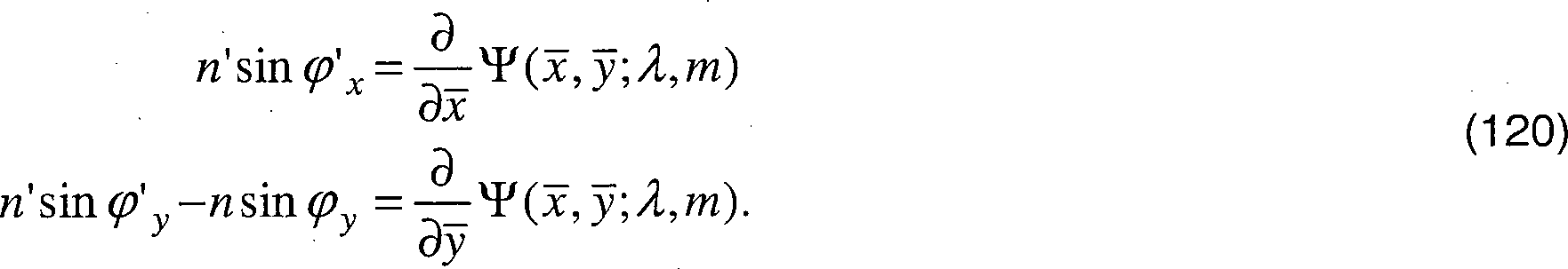
Wenn
Eigenschaften zweiter Ordnung (Krümmungseigenschaften der Wellenfront)Second order properties (wavefront curvature properties)
Um Wellenfronteigenschaften zu beschreiben, wird vorgeschlagen, zuerst die Strahldurchrechnung (”ray tracing”) eines Hauptstrahls, welcher durch eine Bewertungsstelle des optischen Element verläuft, durchzuführen. Der Hauptstrahl unterscheidet sich somit von etwaigen Nachbarstrahlen, welche abseits der Bewertungsstelle verlaufen. Ein Hauptstrahl ist im beispielhaften Fall eines Brillenglases insbesondere ein Lichtstahl, welcher ausgehend vom Objektpunkt durch die Mitte der Eintrittspupille verläuft. Die Eintrittspupille fällt bei Blickbewegungen mit dem Augendrehpunkt und nicht notwendigerweise mit der physikalischen Pupille des Auges zusammen. Die Winkel φx, φy, φ'x, φ'y und damit die Vektoren
Zusätzlich wird vorgeschlagen, außer einem lokalen Koordinatensystem, das zur Beschreibung der Grundfläche dient und in dem auch der einfallende und der ausfallende Strahl beschrieben werden, noch weitere Koordinatensysteme einzuführen.In addition, it is proposed, in addition to a local coordinate system, which is used to describe the base area and in which the incident and the outgoing beam are described to introduce even more coordinate systems.
Das Koordinatensystem (x, y, z) dient dazu, die einfallende Wellenfront zu beschreiben und ist so gerichtet, dass die z-Achse in Lichtrichtung entlang der einfallenden Strahlrichtung
Das Koordinatensystem (x', y', z') dient dazu, die ausfallende Wellenfront zu beschreiben und ist so gerichtet, dass die z'-Achse in Lichtrichtung entlang der ausfallenden Strahlrichtung
Die Koordinaten eines räumlichen Vektors können entweder durch die Größe
Vorzugsweise wird die gegenseitige Lage der Koordinatensysteme durch 
Die Hilfswinkel φ, φ', χ, χ' in Gleichung (121) müssen durch die vor der Wellenfrontdurchrechnung bekannten Größen φx, φy, φ'x, φ'y, ausgedrückt werden. Die Matrizen 
Aus den obigen Gleichungen (123) und (124) folgt, dass 
Ist die einfallende Wellenfront im lokalen Koordinatensystem (x, y, z) durch WIn(x, y), die brechende Grundfläche im System 
Die einzelnen Termen der Gleichung (127) entsprechend dabei den Termen der BAD Gleichung
In Gleichung (127) stehen die hochgestellten Symbole für Ableitungen. Für eine beliebige Funktion h(x, y) gilt:
Die Funktion h(x, y) in der Formel (129) spielt dabei wahlweise die Rolle der Funktionen WIn(x, y), W'Out(x', y'), 
Zusätzlich geht in die Gleichung (127) die Matrix 
Die Ableitung k-ter Ordnung


Explizit gilt für die ersten drei OrdnungenExplicitly valid for the first three orders

Nachfolgend werden einige spezielle Fälle von optischen Systemen, insbesondere von Brillengläsern mit POE, betrachtet. So gilt bei einem senkrechten Lichteinfall:
ν = n' – n;
ν = n '- n;
Für die Gleichung (127) ergibt sich: 
Bei einem eindimensionalen Problem (Meridionalebene) treten statt gemischter Ableitungen nach
Folglich kann Gleichung (127) als
Bei einem senkrechten Lichteinfall und einem eindimensionalen Problem treten statt gemischter Ableitungen nach
ν = n' – n
ν = n '- n
Folglich kann Gleichung (127) als
Eigenschaften höherer Ordnung der Wellenfront (Eigenschaften 3., 4, ... Ordnung)Higher-order properties of the wavefront (
Analog zu Gleichung (127) gilt für Ableitungen 3. Ordnung 

Gleichungen für die noch höheren Ordnungen k = 4, 5, ... können analog gebildet werden.Equations for the even higher orders k = 4, 5, ... can be formed analogously.
Mit der oben beschriebenen Vorgehensweise ist es möglich, ein optisches System (z. B. ein Brillenglas) mit zumindest einem diffraktiven Gitter exakt zu beschreiben. Insbesondere ist es möglich, die Eigenschaften zweiter oder höherer Ordnung der aus dem optischen System austretenden Wellenfront exakt zu bestimmen. Anhand der. Eigenschaften der Wellenfront zweiter Ordnung oder höherer Ordnung können die Abbildungsfehler des optischen Elements (z. B. des Brillenglases) in an sich bekannter Weise ermittelt werden. Diesbezüglich wird insbesondere auf die Druckschrift
Das Basisgitter eines jeden Basisglases kann unter Berücksichtigung der Abbildungseigenschaften zweiter und/oder gegebenenfalls höherer Ordnung, berechnet bzw. optimiert werden. Wie oben beschrieben, können die Abbildungseigenschaften zweiter und/oder gegebenenfalls höherer Ordnung mittels der oben beschriebenen Wellenfrontdurchrechnung exakt berechnet werden.The basic lattice of each base glass can be calculated or optimized taking into account the imaging properties of the second and / or higher order. As described above, the imaging properties of the second and / or possibly higher order can be calculated exactly by means of the wavefront computation described above.
Alternativ kann statt einer Optimierung des Basisgitters und zumindest einer ref raktiven Fläche das Gitter lediglich pauschal in Abhängigkeit von der Rezeptwirkung des Brillenglases oder einer in Abhängigkeit von der Rezeptwirkung ermittelten Sollwirkung berechnet werden. Wie oben dargelegt wurde, ist auch ein so berechnetes Basisgitter geeignet, den Farbsaum für einen Bereich von Wirkungen auch bei nicht rotationssymmetrischen Brillengläsern zumindest teilweise zu korrigieren.Alternatively, instead of optimizing the base grid and at least one refactive area, the grid may only be calculated as a whole depending on the prescription effect of the spectacle lens or a desired action determined as a function of the prescription effect. As explained above, a basic grid calculated in this way is also suitable for at least partially correcting the color fringe for a range of effects, even with non-rotationally symmetrical spectacle lenses.
BezugszeichenlisteLIST OF REFERENCE NUMBERS
- 1010
-
einfallende Wellenfront
10 incident wave front 10 - 1212
- Grenzflächeinterface
- 1414
- periodische Struktur (diffraktives Gitter)periodic structure (diffractive grating)
- 1616
- ausfallende Wellenfrontfailing wavefront
- 2020
- Prismaprism
- 3030
- Korrekturbereichecorrection areas
- 3232
- Trennungslinie der KorrekturbereicheDividing line of the correction areas
- 100100
- optisches Element/System (z. B. Brillenglas)optical element / system (eg spectacle lens)
- 102102
- einfallender Strahl;incident beam;
- 104, 106104, 106
- refraktive Grenzflächenrefractive interfaces
- 108108
- ausfallender Strahloutgoing beam
- 108-m108-m
- ausfallender Strahl der m-ten Beugungsordnungoutgoing beam of the mth diffraction order
- 110110
- einfallende Wellenfrontincident wave front
- 112112
- ausfallende Wellenfrontfailing wavefront
- 122122
- diffraktives Gitterdiffractive grating
- 114114
- optisches Materialoptical material
- 116116
- Durchgang durch das optische MaterialPassage through the optical material
- 122a122a
- Gitterliniengridlines
- 112b112b
- projezierte Gitterlinienprojected grid lines
- 124124
- Einfallsebeneplane of incidence
- 126126
- orthogonale Trajektorienorthogonal trajectories
- 130–134130-134
- Schritte des Übergangs zwischen einer Periodenfunktion und einer PhasenfunktionSteps of transition between a period function and a phase function
ZITATE ENTHALTEN IN DER BESCHREIBUNG QUOTES INCLUDE IN THE DESCRIPTION
Diese Liste der vom Anmelder aufgeführten Dokumente wurde automatisiert erzeugt und ist ausschließlich zur besseren Information des Lesers aufgenommen. Die Liste ist nicht Bestandteil der deutschen Patent- bzw. Gebrauchsmusteranmeldung. Das DPMA übernimmt keinerlei Haftung für etwaige Fehler oder Auslassungen.This list of the documents listed by the applicant has been generated automatically and is included solely for the better information of the reader. The list is not part of the German patent or utility model application. The DPMA assumes no liability for any errors or omissions.
Zitierte PatentliteraturCited patent literature
- WO 2008/089999 A1 [0118, 0228, 0253, 0262, 0312] WO 2008/089999 A1 [0118, 0228, 0253, 0262, 0312]
- WO 2008089999 A1 [0255] WO 2008089999 A1 [0255]
Zitierte Nicht-PatentliteraturCited non-patent literature
- „Optik und Technik der Brille” von H. Diepes und R. Blendowske, 2002 Optische Fachveröffentlichung GmbH, Heidelberg, Seite 485 ff. [0229] "Optics and Technology of the Glasses" by H. Diepes and R. Blendowske, 2002 Optical Disclosure GmbH, Heidelberg, page 485 et seq. [0229]
- G. Esser, W. Becken, W. Müller, P. Baumbach, J. Arasa, and D. Uttenweiler, „Derivation of the refraction equations for higher-order aberrations of local wavefronts at oblique incidence”, JOSA. A, Vol. 27, Nr. 2, Februar 2010, Seiten 218 – 237 [0235] G. Esser, W. Becken, W. Müller, P. Baumbach, J. Arasa, and D. Uttenweiler, "Derivation of the refraction equations for higher-order aberrations of local wavefronts at oblique incidence", JOSA. A, Vol. 27, No. 2, February 2010, pages 218-237 [0235]
- G. Esser, W. Becken, W. Müller, P. Baumbach, J. Arasa, und D. Uttenweiler, „Derivation of the refraction equations for higher-order aberrations of local wavefronts at oblique incidence”, JOSA. A, Vol. 27, Nr. 2, Februar 2010, Seiten 218–237 [0238] G. Esser, W. Becken, W. Müller, P. Baumbach, J. Arasa, and D. Uttenweiler, "Derivation of the refraction equations for higher-order aberrations of local wavefronts at oblique incidence", JOSA. A, Vol. 27, No. 2, February 2010, pages 218-237 [0238]
- G. Esser, W. Becken, W. Müller, P.. Baumbach, J. Arasa, und D. Uttenweiler, „Derivation of the refraction equations for higher-order aberrations of local wavefronts at oblique incidence”, JOSA. A, Vol. 27, Nr. 2, Februar 2010, Seiten 218–237 [0264] Baumer, J. Arasa, and D. Uttenweiler, "Derivation of the refraction equations for higher-order aberrations of local wavefronts at oblique incidence," JOSA. A, Vol. 27, No. 2, February 2010, pages 218-237 [0264]
- G. Esser, W. Becken, W. Müller, P. Baumbach, J. Arasa und D. Uttenweiler, „Derivation of the refraction equations for higher-order aberrations of local wavefronts at oblique incidence”, J. Opt. Soc. Am. A/Vol. 27, No. 2/February 2010 [0300] G. Esser, W. Becken, W. Müller, P. Baumbach, J. Arasa and D. Uttenweiler, "Derivation of the refraction equations for higher-order aberrations of local wavefronts at oblique incidence", J. Opt. Soc. At the. A / Vol. 27, no. 2 / February 2010 [0300]
- W. Becken et al. „Brillengläser im Sport: Optimierung der Abbildungseigenschaften unter physiologischen Aspekten”, Z. Med. Phys., 17 (2007), Seiten 56–66 [0312] W. Becken et al. "Spectacle lenses in sports: Optimization of imaging properties under physiological aspects", Z. Med. Phys., 17 (2007), pages 56-66 [0312]
- G. Esser „Derivation of the refraction equations for higher-order aberrations of local wavefronts at oblique incidence”, JOSA A, Vol. 27, Nr. 2, Februar 2010, Seiten 218–237 [0312] G. Esser "Derivation of the refraction equations for higher-order aberrations of local wavefronts at oblique incidence", JOSA A, Vol. 27, No. 2, February 2010, pages 218-237 [0312]
Claims (33)

Priority Applications (5)
| Application Number | Priority Date | Filing Date | Title |
|---|---|---|---|
| DE102010051637.6A DE102010051637B4 (en) | 2010-11-17 | 2010-11-17 | Method and device for manufacturing a series of base lenses, series of spectacle lenses, method and device for manufacturing a spectacle lens, progressive spectacle lens and astigmatic spectacle lens |
| ES11790559.6T ES2619402T3 (en) | 2010-11-17 | 2011-11-16 | Method for determining a basic system of diffraction gratings for the correction of the color space of glasses glasses |
| PCT/EP2011/005779 WO2012065735A1 (en) | 2010-11-17 | 2011-11-16 | Method for determining a base system of diffraction gratings for colour fringe correction of spectacle lenses |
| US13/988,239 US9022560B2 (en) | 2010-11-17 | 2011-11-16 | Method for determining a base system of diffraction gratings for color fringe correction of spectacle lenses |
| EP11790559.6A EP2641122B1 (en) | 2010-11-17 | 2011-11-16 | Method for determining a base system of diffraction gratings for colour fringe correction of spectacle lenses |
Applications Claiming Priority (1)
| Application Number | Priority Date | Filing Date | Title |
|---|---|---|---|
| DE102010051637.6A DE102010051637B4 (en) | 2010-11-17 | 2010-11-17 | Method and device for manufacturing a series of base lenses, series of spectacle lenses, method and device for manufacturing a spectacle lens, progressive spectacle lens and astigmatic spectacle lens |
Publications (2)
| Publication Number | Publication Date |
|---|---|
| DE102010051637A1 true DE102010051637A1 (en) | 2012-05-24 |
| DE102010051637B4 DE102010051637B4 (en) | 2023-06-22 |
Family
ID=45065859
Family Applications (1)
| Application Number | Title | Priority Date | Filing Date |
|---|---|---|---|
| DE102010051637.6A Active DE102010051637B4 (en) | 2010-11-17 | 2010-11-17 | Method and device for manufacturing a series of base lenses, series of spectacle lenses, method and device for manufacturing a spectacle lens, progressive spectacle lens and astigmatic spectacle lens |
Country Status (5)
| Country | Link |
|---|---|
| US (1) | US9022560B2 (en) |
| EP (1) | EP2641122B1 (en) |
| DE (1) | DE102010051637B4 (en) |
| ES (1) | ES2619402T3 (en) |
| WO (1) | WO2012065735A1 (en) |
Cited By (5)
| Publication number | Priority date | Publication date | Assignee | Title |
|---|---|---|---|---|
| DE102012020363A1 (en) | 2012-10-17 | 2014-04-17 | Rodenstock Gmbh | Production of microstructured molds or stamps |
| DE102012020452A1 (en) | 2012-10-17 | 2014-04-17 | Rodenstock Gmbh | Production of spectacle lenses with protected microstructures |
| DE102012023025A1 (en) | 2012-11-23 | 2014-05-28 | Rodenstock Gmbh | Production of microstructured spectacle lenses by means of a transfer layer |
| DE102013005714A1 (en) | 2013-04-02 | 2014-10-02 | Rodenstock Gmbh | Production of microstructured spectacle lenses in the manufacture of prescription glasses |
| DE102012025740B3 (en) | 2012-10-17 | 2022-07-21 | Rodenstock Gmbh | Production of microstructured stamps |
Families Citing this family (2)
| Publication number | Priority date | Publication date | Assignee | Title |
|---|---|---|---|---|
| DE102015205721B4 (en) * | 2015-03-30 | 2017-01-19 | Rodenstock Gmbh | Method for creating a design of a prescription surface of a multifocal lens and multifocal lens with such a prescription surface |
| DE102022001664B3 (en) | 2022-05-12 | 2023-07-06 | Rodenstock Gmbh | Myopia stop glasses with continuous distribution of effects |
Citations (4)
| Publication number | Priority date | Publication date | Assignee | Title |
|---|---|---|---|---|
| US6070980A (en) * | 1997-04-08 | 2000-06-06 | Asahi Kogaku Kogyo Kabushiki Kaisha | Spectacle lens |
| US20030063254A1 (en) * | 2001-04-11 | 2003-04-03 | Piers Patricia Ann | Ophthalmic lens |
| WO2005098518A1 (en) * | 2004-04-05 | 2005-10-20 | Advanced Medical Optics, Inc. | Ophthalmic lenses capable of reducing chromatic aberration |
| WO2008089999A1 (en) | 2007-01-25 | 2008-07-31 | Rodenstock Gmbh | Method for optimising a spectacle lens |
Family Cites Families (8)
| Publication number | Priority date | Publication date | Assignee | Title |
|---|---|---|---|---|
| FR2642855B1 (en) * | 1989-02-06 | 1991-05-17 | Essilor Int | OPTICAL LENS FOR THE CORRECTION OF ASTIGMATISM |
| DE19701312A1 (en) | 1997-01-16 | 1998-07-23 | Zeiss Carl Fa | Spectacle lens with spherical front and multifocal back, and method for its production |
| US6619799B1 (en) | 1999-07-02 | 2003-09-16 | E-Vision, Llc | Optical lens system with electro-active lens having alterably different focal lengths |
| US6851803B2 (en) | 2002-10-24 | 2005-02-08 | C. Benjamin Wooley | Ophthalmic lenses with reduced chromatic blur |
| SE0203564D0 (en) * | 2002-11-29 | 2002-11-29 | Pharmacia Groningen Bv | Multifocal opthalmic lens |
| US7922326B2 (en) * | 2005-10-25 | 2011-04-12 | Abbott Medical Optics Inc. | Ophthalmic lens with multiple phase plates |
| WO2008090743A1 (en) * | 2007-01-25 | 2008-07-31 | Nikon Corporation | Spectacles lens |
| US8317321B2 (en) | 2007-07-03 | 2012-11-27 | Pixeloptics, Inc. | Multifocal lens with a diffractive optical power region |
-
2010
- 2010-11-17 DE DE102010051637.6A patent/DE102010051637B4/en active Active
-
2011
- 2011-11-16 ES ES11790559.6T patent/ES2619402T3/en active Active
- 2011-11-16 WO PCT/EP2011/005779 patent/WO2012065735A1/en active Application Filing
- 2011-11-16 US US13/988,239 patent/US9022560B2/en active Active
- 2011-11-16 EP EP11790559.6A patent/EP2641122B1/en active Active
Patent Citations (4)
| Publication number | Priority date | Publication date | Assignee | Title |
|---|---|---|---|---|
| US6070980A (en) * | 1997-04-08 | 2000-06-06 | Asahi Kogaku Kogyo Kabushiki Kaisha | Spectacle lens |
| US20030063254A1 (en) * | 2001-04-11 | 2003-04-03 | Piers Patricia Ann | Ophthalmic lens |
| WO2005098518A1 (en) * | 2004-04-05 | 2005-10-20 | Advanced Medical Optics, Inc. | Ophthalmic lenses capable of reducing chromatic aberration |
| WO2008089999A1 (en) | 2007-01-25 | 2008-07-31 | Rodenstock Gmbh | Method for optimising a spectacle lens |
Non-Patent Citations (3)
| Title |
|---|
| "Optik und Technik der Brille" von H. Diepes und R. Blendowske, 2002 Optische Fachveröffentlichung GmbH, Heidelberg, Seite 485 ff. |
| G. Esser, W. Becken, W. Müller, P. Baumbach, J. Arasa, and D. Uttenweiler, "Derivation of the refraction equations for higher-order aberrations of local wavefronts at oblique incidence", JOSA. A, Vol. 27, Nr. 2, Februar 2010, Seiten 218 - 237 |
| W. Becken et al. "Brillengläser im Sport: Optimierung der Abbildungseigenschaften unter physiologischen Aspekten", Z. Med. Phys., 17 (2007), Seiten 56-66 |
Cited By (11)
| Publication number | Priority date | Publication date | Assignee | Title |
|---|---|---|---|---|
| DE102012020363A1 (en) | 2012-10-17 | 2014-04-17 | Rodenstock Gmbh | Production of microstructured molds or stamps |
| DE102012020452A1 (en) | 2012-10-17 | 2014-04-17 | Rodenstock Gmbh | Production of spectacle lenses with protected microstructures |
| WO2014060097A1 (en) | 2012-10-17 | 2014-04-24 | Rodenstock Gmbh | Production of ophthalmic lenses with protected microstructures |
| WO2014060098A1 (en) | 2012-10-17 | 2014-04-24 | Rodenstock Gmbh | Creation of microstructured casting moulds or punches |
| DE102012020363B4 (en) | 2012-10-17 | 2022-07-07 | Rodenstock Gmbh | Production of microstructured casting molds |
| DE102012025740B3 (en) | 2012-10-17 | 2022-07-21 | Rodenstock Gmbh | Production of microstructured stamps |
| DE102012023025A1 (en) | 2012-11-23 | 2014-05-28 | Rodenstock Gmbh | Production of microstructured spectacle lenses by means of a transfer layer |
| WO2014079559A1 (en) | 2012-11-23 | 2014-05-30 | Rodenstock Gmbh | Producing microstructured spectacle lenses by means of transfer layer |
| US10274749B2 (en) | 2012-11-23 | 2019-04-30 | Rodenstock Gmbh | Producing microstructured spectacle lenses by means of transfer layer |
| DE102013005714A1 (en) | 2013-04-02 | 2014-10-02 | Rodenstock Gmbh | Production of microstructured spectacle lenses in the manufacture of prescription glasses |
| WO2014161639A1 (en) | 2013-04-02 | 2014-10-09 | Rodenstock Gmbh | Creation of microstructured spectacle lenses in prescription lens production |
Also Published As
| Publication number | Publication date |
|---|---|
| DE102010051637B4 (en) | 2023-06-22 |
| US9022560B2 (en) | 2015-05-05 |
| EP2641122B1 (en) | 2017-01-18 |
| ES2619402T3 (en) | 2017-06-26 |
| WO2012065735A1 (en) | 2012-05-24 |
| EP2641122A1 (en) | 2013-09-25 |
| US20130235337A1 (en) | 2013-09-12 |
Similar Documents
| Publication | Publication Date | Title |
|---|---|---|
| DE102010051762B4 (en) | Computer-implemented method and device for evaluating at least one imaging property of an optical element, computer program product, storage medium and method and device for producing an optical element | |
| EP2641123B1 (en) | Method for optimizing a spectacle lens with a diffraction grating | |
| EP2641122B1 (en) | Method for determining a base system of diffraction gratings for colour fringe correction of spectacle lenses | |
| DE60016219T2 (en) | BREAKING / BENDING MULTIFOCALLINSE | |
| EP2389139B1 (en) | Lens having discrete circular refractive power profile | |
| EP2115527A1 (en) | Method for optimising a spectacle lens | |
| EP3555695A2 (en) | Progressive spectacle lens having a variable refractive index and method for the design and production thereof | |
| EP2641125B1 (en) | Spectacle lens with asymmetric diffraction grating for colour fringe correction | |
| DE102011055777B4 (en) | Optical device, optical element and method of making the same | |
| DE102005028933A1 (en) | Astigmatic intraocular lens e.g. for correcting astigmatic ametropia, has toroidal refractive front face and toroidal refractive rear face with intraocular lens also has toroidal refractive lens surface | |
| EP3669230B1 (en) | Optimizing a spectacle lens taking account of a vision model | |
| DE102010049168A1 (en) | Regulation and individualization-dependent modification of the temporal peripheral target astigmatism and adaptation of the object distance function to changed object distances for proximity and / or distance | |
| DE102010047846B4 (en) | Optical lens and method of manufacturing an optical lens | |
| EP2710428B1 (en) | Method for calculating and optimizing an eyeglass lens taking into consideration higher-order imaging errors | |
| DE102013100680A1 (en) | Wave front manipulator for optical system used in e.g. observation optical device like telescope, has two optical components arranged movable relative to each other, opposing optical axis and set rotatable along vertical rotation axis | |
| EP3814828B1 (en) | Computer-implemented method, data processing system for producing a target design and computer program, storage medium having instructions for producing a target design, method for providing a spectacle lens, storage medium having a numerical representation of a spectacle lens and method for manufacturing a spectacle lens | |
| DE102022001664B3 (en) | Myopia stop glasses with continuous distribution of effects | |
| DE102017118219A1 (en) | Computer-implemented method for creating a target design for optimizing a free-form surface of a spectacle lens, computer program, storage medium and computer | |
| WO2019141386A1 (en) | Progressive spectacle lens with a variable refractive index, and method for designing and producing same |
Legal Events
| Date | Code | Title | Description |
|---|---|---|---|
| R016 | Response to examination communication | ||
| R016 | Response to examination communication | ||
| R018 | Grant decision by examination section/examining division |