DE102010043202A1 - Brake booster and method for operating a brake booster - Google Patents
Brake booster and method for operating a brake booster Download PDFInfo
- Publication number
- DE102010043202A1 DE102010043202A1 DE102010043202A DE102010043202A DE102010043202A1 DE 102010043202 A1 DE102010043202 A1 DE 102010043202A1 DE 102010043202 A DE102010043202 A DE 102010043202A DE 102010043202 A DE102010043202 A DE 102010043202A DE 102010043202 A1 DE102010043202 A1 DE 102010043202A1
- Authority
- DE
- Germany
- Prior art keywords
- force
- brake booster
- power transmission
- transmission unit
- input
- Prior art date
- Legal status (The legal status is an assumption and is not a legal conclusion. Google has not performed a legal analysis and makes no representation as to the accuracy of the status listed.)
- Withdrawn
Links
Images

Classifications
-
- B—PERFORMING OPERATIONS; TRANSPORTING
- B60—VEHICLES IN GENERAL
- B60T—VEHICLE BRAKE CONTROL SYSTEMS OR PARTS THEREOF; BRAKE CONTROL SYSTEMS OR PARTS THEREOF, IN GENERAL; ARRANGEMENT OF BRAKING ELEMENTS ON VEHICLES IN GENERAL; PORTABLE DEVICES FOR PREVENTING UNWANTED MOVEMENT OF VEHICLES; VEHICLE MODIFICATIONS TO FACILITATE COOLING OF BRAKES
- B60T13/00—Transmitting braking action from initiating means to ultimate brake actuator with power assistance or drive; Brake systems incorporating such transmitting means, e.g. air-pressure brake systems
- B60T13/10—Transmitting braking action from initiating means to ultimate brake actuator with power assistance or drive; Brake systems incorporating such transmitting means, e.g. air-pressure brake systems with fluid assistance, drive, or release
- B60T13/24—Transmitting braking action from initiating means to ultimate brake actuator with power assistance or drive; Brake systems incorporating such transmitting means, e.g. air-pressure brake systems with fluid assistance, drive, or release the fluid being gaseous
- B60T13/46—Vacuum systems
- B60T13/52—Vacuum systems indirect, i.e. vacuum booster units
-
- B—PERFORMING OPERATIONS; TRANSPORTING
- B60—VEHICLES IN GENERAL
- B60T—VEHICLE BRAKE CONTROL SYSTEMS OR PARTS THEREOF; BRAKE CONTROL SYSTEMS OR PARTS THEREOF, IN GENERAL; ARRANGEMENT OF BRAKING ELEMENTS ON VEHICLES IN GENERAL; PORTABLE DEVICES FOR PREVENTING UNWANTED MOVEMENT OF VEHICLES; VEHICLE MODIFICATIONS TO FACILITATE COOLING OF BRAKES
- B60T13/00—Transmitting braking action from initiating means to ultimate brake actuator with power assistance or drive; Brake systems incorporating such transmitting means, e.g. air-pressure brake systems
- B60T13/10—Transmitting braking action from initiating means to ultimate brake actuator with power assistance or drive; Brake systems incorporating such transmitting means, e.g. air-pressure brake systems with fluid assistance, drive, or release
- B60T13/66—Electrical control in fluid-pressure brake systems
- B60T13/662—Electrical control in fluid-pressure brake systems characterised by specified functions of the control system components
-
- B—PERFORMING OPERATIONS; TRANSPORTING
- B60—VEHICLES IN GENERAL
- B60T—VEHICLE BRAKE CONTROL SYSTEMS OR PARTS THEREOF; BRAKE CONTROL SYSTEMS OR PARTS THEREOF, IN GENERAL; ARRANGEMENT OF BRAKING ELEMENTS ON VEHICLES IN GENERAL; PORTABLE DEVICES FOR PREVENTING UNWANTED MOVEMENT OF VEHICLES; VEHICLE MODIFICATIONS TO FACILITATE COOLING OF BRAKES
- B60T13/00—Transmitting braking action from initiating means to ultimate brake actuator with power assistance or drive; Brake systems incorporating such transmitting means, e.g. air-pressure brake systems
- B60T13/74—Transmitting braking action from initiating means to ultimate brake actuator with power assistance or drive; Brake systems incorporating such transmitting means, e.g. air-pressure brake systems with electrical assistance or drive
- B60T13/745—Transmitting braking action from initiating means to ultimate brake actuator with power assistance or drive; Brake systems incorporating such transmitting means, e.g. air-pressure brake systems with electrical assistance or drive acting on a hydraulic system, e.g. a master cylinder
-
- B—PERFORMING OPERATIONS; TRANSPORTING
- B60—VEHICLES IN GENERAL
- B60T—VEHICLE BRAKE CONTROL SYSTEMS OR PARTS THEREOF; BRAKE CONTROL SYSTEMS OR PARTS THEREOF, IN GENERAL; ARRANGEMENT OF BRAKING ELEMENTS ON VEHICLES IN GENERAL; PORTABLE DEVICES FOR PREVENTING UNWANTED MOVEMENT OF VEHICLES; VEHICLE MODIFICATIONS TO FACILITATE COOLING OF BRAKES
- B60T17/00—Component parts, details, or accessories of power brake systems not covered by groups B60T8/00, B60T13/00 or B60T15/00, or presenting other characteristic features
- B60T17/18—Safety devices; Monitoring
- B60T17/22—Devices for monitoring or checking brake systems; Signal devices
-
- B—PERFORMING OPERATIONS; TRANSPORTING
- B60—VEHICLES IN GENERAL
- B60T—VEHICLE BRAKE CONTROL SYSTEMS OR PARTS THEREOF; BRAKE CONTROL SYSTEMS OR PARTS THEREOF, IN GENERAL; ARRANGEMENT OF BRAKING ELEMENTS ON VEHICLES IN GENERAL; PORTABLE DEVICES FOR PREVENTING UNWANTED MOVEMENT OF VEHICLES; VEHICLE MODIFICATIONS TO FACILITATE COOLING OF BRAKES
- B60T7/00—Brake-action initiating means
- B60T7/02—Brake-action initiating means for personal initiation
- B60T7/04—Brake-action initiating means for personal initiation foot actuated
- B60T7/042—Brake-action initiating means for personal initiation foot actuated by electrical means, e.g. using travel or force sensors
-
- B—PERFORMING OPERATIONS; TRANSPORTING
- B60—VEHICLES IN GENERAL
- B60T—VEHICLE BRAKE CONTROL SYSTEMS OR PARTS THEREOF; BRAKE CONTROL SYSTEMS OR PARTS THEREOF, IN GENERAL; ARRANGEMENT OF BRAKING ELEMENTS ON VEHICLES IN GENERAL; PORTABLE DEVICES FOR PREVENTING UNWANTED MOVEMENT OF VEHICLES; VEHICLE MODIFICATIONS TO FACILITATE COOLING OF BRAKES
- B60T7/00—Brake-action initiating means
- B60T7/12—Brake-action initiating means for automatic initiation; for initiation not subject to will of driver or passenger
-
- B—PERFORMING OPERATIONS; TRANSPORTING
- B60—VEHICLES IN GENERAL
- B60T—VEHICLE BRAKE CONTROL SYSTEMS OR PARTS THEREOF; BRAKE CONTROL SYSTEMS OR PARTS THEREOF, IN GENERAL; ARRANGEMENT OF BRAKING ELEMENTS ON VEHICLES IN GENERAL; PORTABLE DEVICES FOR PREVENTING UNWANTED MOVEMENT OF VEHICLES; VEHICLE MODIFICATIONS TO FACILITATE COOLING OF BRAKES
- B60T8/00—Arrangements for adjusting wheel-braking force to meet varying vehicular or ground-surface conditions, e.g. limiting or varying distribution of braking force
- B60T8/32—Arrangements for adjusting wheel-braking force to meet varying vehicular or ground-surface conditions, e.g. limiting or varying distribution of braking force responsive to a speed condition, e.g. acceleration or deceleration
- B60T8/34—Arrangements for adjusting wheel-braking force to meet varying vehicular or ground-surface conditions, e.g. limiting or varying distribution of braking force responsive to a speed condition, e.g. acceleration or deceleration having a fluid pressure regulator responsive to a speed condition
- B60T8/44—Arrangements for adjusting wheel-braking force to meet varying vehicular or ground-surface conditions, e.g. limiting or varying distribution of braking force responsive to a speed condition, e.g. acceleration or deceleration having a fluid pressure regulator responsive to a speed condition co-operating with a power-assist booster means associated with a master cylinder for controlling the release and reapplication of brake pressure through an interaction with the power assist device, i.e. open systems
- B60T8/441—Arrangements for adjusting wheel-braking force to meet varying vehicular or ground-surface conditions, e.g. limiting or varying distribution of braking force responsive to a speed condition, e.g. acceleration or deceleration having a fluid pressure regulator responsive to a speed condition co-operating with a power-assist booster means associated with a master cylinder for controlling the release and reapplication of brake pressure through an interaction with the power assist device, i.e. open systems using hydraulic boosters
-
- B—PERFORMING OPERATIONS; TRANSPORTING
- B60—VEHICLES IN GENERAL
- B60T—VEHICLE BRAKE CONTROL SYSTEMS OR PARTS THEREOF; BRAKE CONTROL SYSTEMS OR PARTS THEREOF, IN GENERAL; ARRANGEMENT OF BRAKING ELEMENTS ON VEHICLES IN GENERAL; PORTABLE DEVICES FOR PREVENTING UNWANTED MOVEMENT OF VEHICLES; VEHICLE MODIFICATIONS TO FACILITATE COOLING OF BRAKES
- B60T2201/00—Particular use of vehicle brake systems; Special systems using also the brakes; Special software modules within the brake system controller
- B60T2201/12—Pre-actuation of braking systems without significant braking effect; Optimizing brake performance by reduction of play between brake pads and brake disc
Landscapes
- Engineering & Computer Science (AREA)
- Transportation (AREA)
- Mechanical Engineering (AREA)
- Physics & Mathematics (AREA)
- Fluid Mechanics (AREA)
- Braking Systems And Boosters (AREA)
Abstract
Die Erfindung betrifft einen Bremskraftverstärker (1) mit einem durch einen Fahrer betätigbaren Eingangselement (2), einem Aktuator zum Erzeugen einer Unterstützungskraft (Fsup), einem Ausgangselement (6), welches durch das Eingangselement (2) und/oder den Aktuator mit einer Eingangskraft (Fin) bzw. der Unterstützungskraft (Fsup) beaufschlagbar ist und durch welches ein Kolben eines Hauptbremszylinders mit einer Betätigungskraft beaufschlagbar ist, und einer Kraftübertragungseinheit (5) mit elastischen Eigenschaften, welche zwischen dem Eingangselement (2) und dem Aktuator einerseits und dem Ausgangselement (6) andererseits angeordnet ist und die Eingangskraft (Fin) und/oder die Unterstützungskraft (Fsup) auf das Ausgangselement (6) überträgt. Auerdem ist eine Vorspanneinheit (8) vorgesehen, welche derart auf die Kraftübertragungseinheit (5) einwirkt, dass sie die Kraftübertragungseinheit (5) im Ruhezustand des Bremskraftverstärkers (1) mit einem Kräftepaar beaufschlagt. Gemäß einem Verfahren zum Betrieb des Bremskraftverstärkers wird im Vorfeld eines zu erwartenden Bremswunsches oder unmittelbar nach Erkennen eines Bremswunsches in einem Zeitbereich vor oder unmittelbar nach Erkennen einer Betätigung des Eingangselements (2) eine Unterstützungskraft (Fsup) durch den Aktuator erzeugt.The invention relates to a brake booster (1) with an input element (2) which can be actuated by a driver, an actuator for generating a support force (Fsup), an output element (6) which is provided with an input force by the input element (2) and / or the actuator (Fin) or the support force (Fsup) can be acted upon and through which a piston of a master brake cylinder can be acted upon with an actuating force, and a force transmission unit (5) with elastic properties, which between the input element (2) and the actuator on the one hand and the output element ( 6) is arranged on the other hand and transmits the input force (Fin) and / or the support force (Fsup) to the output element (6). In addition, a pretensioning unit (8) is provided which acts on the power transmission unit (5) in such a way that it applies a pair of forces to the power transmission unit (5) when the brake booster (1) is in the idle state. According to a method for operating the brake booster, a support force (Fsup) is generated by the actuator in advance of an expected braking request or immediately after a braking request is recognized in a time range before or immediately after an actuation of the input element (2).
Description
Die Erfindung betrifft einen Bremskraftverstärker und ein Verfahren zum Betrieb eines Bremskraftverstärkers.The invention relates to a brake booster and a method for operating a brake booster.
Stand der TechnikState of the art
Bei Fahrzeugen mit herkömmlichen Scheibenbremsen treten während eines ungebremsten Betriebszustandes, also bei unbetätigtem Bremspedal, häufig Energieverluste in Form eines Restbremsmomentes auf, da die Bremsbeläge an der Bremsscheibe schleifen. Dieses Schleifen kann z. B. durch Scheibenschlag und/oder durch in vielen Fällen nicht korrekte Belagrückstellung und Lüftspieleinhaltung hervorgerufen werden.In vehicles with conventional disc brakes, energy losses in the form of a residual braking torque often occur during an unrestrained operating state, that is to say when the brake pedal is de-energized, since the brake linings grind against the brake disk. This grinding can z. B. caused by disc impact and / or in many cases incorrect Belagückstellung and Lüftspieleinhaltung.
Zur Energieeinsparung wurden daher Scheibenbremsen entwickelt, bei welchen sich die Bremse im ungebremsten Zustand in einer sogenannten ”Zero-Drag”-Position befindet, so dass hierbei keinerlei Reibung zwischen den Bremsbelägen und der Bremsscheibe auftritt. Ein entsprechend ausgestalteter Bremssattel wird häufig auch als ”zero-drag-caliper” bezeichnet.To save energy therefore disc brakes have been developed in which the brake is in the unbraked state in a so-called "zero-drag" position, so that in this case no friction between the brake pads and the brake disc occurs. An appropriately designed caliper is often referred to as a "zero-drag caliper".
Nachteilig an derartigen Bremssystemen ist es aber, dass sich dabei oftmals die Bremsbeläge nach dem Lösen des Bremspedals sehr weit von der Bremsscheibe zurückziehen, so dass sich bei Betätigung des Bremsbetätigungselements ein im Vergleich zu herkömmlichen Bremssystemen erhöhter Leer- oder Todweg ergibt. Ein derartiger zusätzlicher Leer- oder Todweg ist aber unerwünscht und sollte daher vermieden oder ausgeglichen werden. Dabei sei darauf hingewiesen, dass sich derartige erhöhte Leer- oder Todwege systembedingt auch unabhängig von ”zero-drag-calipern” ergeben können.A disadvantage of such brake systems, however, is that often the brake pads retract very far from the brake disc after release of the brake pedal, so that when the brake actuating element is actuated, an empty or dead path is increased compared with conventional brake systems. Such an additional empty or dead path is undesirable and should therefore be avoided or compensated. It should be noted that such increased empty or death paths system-related and independent of "zero-drag-calipers" may result.
Bisher war die Kompensation derartiger unerwünschter zusätzlicher Leer- oder Todwege nur durch den Einsatz sogenannter reiner Fremdkraftbremsanlagen realisierbar, bei denen die zur Erzeugung der Bremskraft benötigte Energie von einer oder mehreren Energieversorgungseinrichtungen, jedoch nicht von der physischen Kraft des Fahrzeugführers, erzeugt wird.Previously, the compensation of such unwanted additional empty or dead paths could be realized only by the use of so-called pure power brake systems, in which the energy required to generate the braking force of one or more energy supply devices, but not by the physical force of the driver is generated.
Offenbarung der ErfindungDisclosure of the invention
Ein erfindungsgemäßer Bremskraftverstärker umfasst ein durch einen Fahrer betätigbares Eingangselement, einen Aktuator zum Erzeugen einer Unterstützungskraft, ein Ausgangselement, welches durch das Eingangselement und/oder den Aktuator mit einer Eingangskraft bzw. der Unterstützungskraft beaufschlagbar ist und durch welches ein Kolben eines Hauptbremszylinders mit einer Betätigungskraft beaufschlagbar ist, und eine Kraftübertragungseinheit mit elastischen Eigenschaften, welche zwischen dem Eingangselement und dem Aktuator einerseits und dem Ausgangselement andererseits angeordnet ist und die Eingangskraft und/oder die Unterstützungskraft auf das Ausgangselement überträgt. Außerdem ist eine Vorspanneinheit vorgesehen, welche derart auf die Kraftübertragungseinheit einwirkt, dass sie die Kraftübertragungseinheit im Ruhezustand des Bremskraftverstärkers mit einem Kräftepaar beaufschlagt.A brake booster according to the invention comprises an input element which can be actuated by a driver, an actuator for generating an assisting force, an output element which can be acted upon by the input element and / or the actuator with an input force or the assisting force and by which a piston of a master brake cylinder can be acted upon by an actuating force and a power transmission unit having elastic properties, which is disposed between the input member and the actuator on the one hand and the output member on the other hand and transmits the input force and / or the assisting force to the output member. In addition, a biasing unit is provided, which acts on the power transmission unit such that it acts on the power transmission unit in the idle state of the brake booster with a pair of forces.
Bei einem erfindungsgemäßen Verfahren zum Betrieb eines erfindungsgemäßen Bremskraftverstärkers wird im Vorfeld eines zu erwartenden Bremswunsches oder unmittelbar nach Erkennen eines Bremswunsches in einem Zeitbereich vor oder unmittelbar nach Erkennen einer Betätigung des Eingangselements eine Unterstützungskraft durch den Aktuator erzeugt wird.In a method according to the invention for operating a brake booster according to the invention, an assisting force is generated by the actuator in advance of an expected braking request or immediately after detecting a braking request in a time range before or immediately after detecting an actuation of the input element.
Vorteile der ErfindungAdvantages of the invention
Die Erfindung basiert auf der Grundidee, einen Bremskraftverstärker derart auszugestalten, dass unerwünschte Leer- oder Todwege des Bremssystems ohne spürbaren Einfluss auf die Pedalcharakteristik, z. B. in Form einer Verschiebung des Bremsbetätigungselements, kompensiert werden. Dies wird erfindungsgemäß dadurch erreicht, dass eine Vorspanneinheit derart auf die Kraftübertragungseinheit eines Bremskraftverstärkers einwirkt, dass sie die Kraftübertragungseinheit im Ruhezustand des Bremskraftverstärkers mit einem Kräftepaar beaufschlagt. Wird nun im Vorfeld eines zu erwartenden Bremswunsches oder unmittelbar nach Erkennen eines Bremswunsches in einem Zeitbereich vor oder unmittelbar nach Erkennen einer Betätigung des Eingangselements eine Unterstützungskraft durch den Aktuator erzeugt, so kann durch geeignete Auslegung der Vorspanneinheit und damit des Kräftepaares sowie der im Vorfeld eines zu erwartenden Bremswunsches oder unmittelbar nach Erkennen eines Bremswunsches erzeugten Unterstützungskraft ein vordefinierter Weg am Ausgang des Bremskraftverstärkers und somit an dem Kolben des Hauptbremszylinders überwunden werden, ohne dass ein entsprechender Weg am Eingang des Bremskraftverstärkers und damit an dem Eingangselement vorliegen muss. Der Leer- oder Todweg kann damit kompensiert werden, ohne dass der Fahrer dies, z. B. durch eine entsprechende Verschiebung des Eingangselements, bemerkt.The invention is based on the basic idea to design a brake booster such that unwanted empty or dead paths of the brake system without noticeable effect on the pedal characteristics, z. B. in the form of a shift of the brake actuator, be compensated. This is inventively achieved in that a biasing unit acts on the power transmission unit of a brake booster such that it acts on the power transmission unit in the idle state of the brake booster with a pair of forces. If an assisting force is generated by the actuator in advance of an expected braking request or immediately after detecting a braking request in a time range before or immediately after detecting an actuation of the input element, so by suitable design of the bias unit and thus of the force pair and in the run-up to one expected braking request or immediately after detecting a desired braking assistance generated a predefined path at the output of the brake booster and thus be overcome on the piston of the master cylinder without a corresponding path at the input of the brake booster and thus must be present at the input element. The empty or dead path can thus be compensated without the driver this, z. B. by a corresponding displacement of the input member noticed.
Im Vergleich zur aufwendigen und kostenintensiven Realisierung eines reinen Fremdkraftbremssystems stellt die erfindungsgemäße Ausgestaltung eines Bremskraftverstärkers eine besonders einfache und damit kostengünstige Variante zur Kompensation von Leer- oder Todwegen in Bremssystemen dar. Der erfindungsgemäße Bremskraftverstärker und das erfindungsgemäße Betriebsverfahren zeichnen sich darüber hinaus dadurch aus, dass sowohl Todwege im Bereich des Bremssattels als auch Todwege im Bereich des Hauptbremszylinders kompensiert werden können. Außerdem erfolgt die Kompensation für den Fahrer unmerklich, so dass auch ein hoher Komfort sicher gestellt ist.Compared to the complex and expensive implementation of a pure power-assisted braking system, the inventive design of a brake booster is a particularly simple and therefore cost-effective variant for the compensation of empty or dead paths in braking systems Brake booster and the operating method according to the invention are also characterized by the fact that both death paths in the caliper and death paths in the region of the master cylinder can be compensated. In addition, the compensation for the driver is imperceptible, so that a high level of comfort is ensured.
Eine weitere vorteilhafte Anwendung des erfindungsgemäßen Bremskraftverstärkers oder des erfindungsgemäßen Betriebsverfahrens ergibt sich beim Einsatz in einem Hybrid- oder Elektrofahrzeug. Hier kann der Fremkraftmodus der Bremskraftverstärkers beim Verblenden eines Generatormomentes genutzt werden. Im Falle einer Bremsung wird zunächst der Druck im Rahmen der Todwegkompensation aufgebaut. Falls nun ein generatorisches Moment hinzukommt, kann das hydraulische Bremsmoment entsprechend reduziert werden, so dass das gesamte Bremsmoment konstant bleibt. Hierbei strömt Bremsflüssigkeit aus dem Bremssystem in den Hauptbrenmszylinder zurück, wodurch sich die Kraftübertragungseinheit in Richtung des Bremsbetätigungselements verschiebt. Bei einem herkömmlichen Bremssystem ist der Luftspalt entsprechend groß auszulegen, so dass hierbei kein Kontakt zwischen der Kraftübertragungseinheit und dem Eingangselement entsteht. Mit einem erfindungsgemäßen Bremskraftverstärker bzw. bei Verwendung des erfindungsgemäßen Betriebsverfahrens muss der Luftspalt hingegen nicht vergrößert werden, wodurch unter anderem im Falle eines Verstärkerausfalles kein erhöhter Leerweg vorliegt. Da während der Verblendung keine direkte Verbindung zwischen dem Bremssystem und dem Bremsbetätigungselement besteht, kommt es zu keiner Rückwirkung aus das Bremsbetätigungselement, das heißt die Pedalcharakteristik bleibt konstant.A further advantageous application of the brake booster according to the invention or the operating method according to the invention results when used in a hybrid or electric vehicle. Here, the Fremkraftmodus the brake booster when blending a generator torque can be used. In the case of braking, the pressure is first built up as part of the dead-end compensation. If a regenerative torque is added, the hydraulic braking torque can be correspondingly reduced, so that the entire braking torque remains constant. Here, brake fluid flows back from the brake system in the Hauptbrenmszylinder, whereby the power transmission unit shifts in the direction of the brake actuator. In a conventional brake system, the air gap is designed to be correspondingly large, so that in this case no contact between the power transmission unit and the input element is formed. By contrast, with a brake booster according to the invention or when using the operating method according to the invention, the air gap does not have to be increased, as a result of which, inter alia, in the case of an amplifier failure, there is no increased free travel. Since there is no direct connection between the brake system and the brake actuation element during the veneering, there is no feedback from the brake actuation element, that is, the pedal characteristic remains constant.
Die Erfindung kann unabhängig von dem Typ des Bremskraftverstärkers eingesetzt werden, das heißt der Aktuator des Bremskraftverstärkers kann als pneumatischer oder hydraulischer oder elektrohydraulischer oder elektromechanischer oder elektrothermischer Aktuator ausgestaltet sein.The invention can be used independently of the type of brake booster, that is, the actuator of the brake booster can be configured as a pneumatic or hydraulic or electro-hydraulic or electromechanical or electrothermal actuator.
Da die Kraftübertragungseinheit und insbesondere deren Steifigkeit im Vergleich zu herkömmlichen Bremskraftverstärkern nicht oder nur geringfügig verändert wird, ergibt sich auch im Falle eines Ausfalles des Bremskraftverstärkers kein verändertes Verhalten. Insbesondere tritt keine nennenswerte Erhöhung der notwendigen Betätigungskraft des Fahrers zur Erzielung einer gewünschten Verzögerung auf.Since the power transmission unit and in particular their rigidity in comparison to conventional brake booster is not or only slightly changed, resulting in the case of failure of the brake booster no changed behavior. In particular, no appreciable increase in the driver's necessary operating force to achieve a desired deceleration occurs.
Gemäß einer Ausführungsform der Erfindung ist die Kraftübertragungseinheit, welche als eine elastisch deformierbare Reaktionsscheibe oder eine elastische Federkonstruktion ausgebildet sein kann, derart ausgestaltet, dass eine Abweichung des Verhältnisses der Unterstützungskraft zur Eingangskraft von einem vorgegebenen Verhältnis zu einer Auslenkung der Kraftübertragungseinheit führt.According to one embodiment of the invention, the force transmission unit, which may be formed as an elastically deformable reaction disc or an elastic spring construction, is configured such that a deviation of the ratio of the assisting force to the input force of a predetermined ratio leads to a deflection of the power transmission unit.
Gemäß einer weiteren Ausführungsform der Erfindung weist die Vorspanneinheit eine Krafterzeugungseinheit auf, welche die Kraftübertragungseinheit im Ruhezustand aktiv mit einer ersten Kraft des Kräftepaares beaufschlagt.According to a further embodiment of the invention, the biasing unit to a force generating unit, which actively acts on the power transmission unit in the idle state with a first force of the force pair.
Eine konstruktiv besonders einfache und damit kostensparende Ausführungsform der Erfindung ergibt sich, wenn die Krafterzeugungseinheit als ein im Ruhezustand des Bremskraftverstärkers vorgespanntes Federelement ausgebildet ist, welches sich einseitig an der Kraftübertragungseinheit abstützt. Dabei kann als Federelement beispielsweise eine Rückholfeder des Bremskraftverstärkers oder eine Feder des Hauptbremszylinders dienen.A structurally particularly simple and thus cost-saving embodiment of the invention results when the force generating unit is designed as a biased in the idle state of the brake booster spring element, which is supported on one side of the power transmission unit. In this case, serve as a spring element, for example, a return spring of the brake booster or a spring of the master cylinder.
Eine weitere Reduzierung des Konstruktions- und Kostenaufwandes kann dadurch erreicht werden, dass die zur Erzeugung des Kräftepaares erforderliche zweite Kraft in Form einer Reaktionskraft realisiert wird. Dies kann dadurch erreicht werden, dass die Vorspanneinheit eine Reaktionseinheit umfasst, welche eine Reaktionskraft zu der ersten Kraft erzeugt, welche zusammen mit der ersten Kraft dann das Kräftepaar bildet.A further reduction of the design and cost can be achieved that the required for generating the force couple second force is realized in the form of a reaction force. This can be achieved by the biasing unit comprising a reaction unit which generates a reaction force to the first force, which then forms the force pair together with the first force.
In besonders einfacher Art und Weise kann die Reaktionskraft dadurch erzeugt werden, dass die Reaktionseinheit einen Anschlag umfasst, an welchem sich die Kraftübertragungseinheit unmittelbar oder mittelbar abstützt.In a particularly simple manner, the reaction force can be generated in that the reaction unit comprises a stop on which the power transmission unit is supported directly or indirectly.
Gemäß einer Ausführungsform der Erfindung weist das Eingangselement ein durch den Fahrer betätigbares erstes Teilelement zum Erzeugen der Eingangskraft und ein davon getrenntes zweites Teilelement zur Übertragung der Eingangskraft auf die Kraftübertragungseinheit auf. Der Anschlag ist dabei derart angeordnet, dass sich in Ruhelage des Bremskraftverstärkers das zweite Teilelement des Eingangselements mit seiner der Kraftübertragungseinheit abgewandten Seite daran abstützt. Diese Ausführungsform hat den Vorteil, dass der Anschlag nicht unmittelbar an der Kraftübertragungseinheit, sondern in einem Bereich zwischen der Kraftübertragungseinheit und dem Eingangselement angeordnet sein kann, was die konstruktive Flexibilität deutlich erhöht. Dadurch kann auf konkrete Rahmenbedingungen des Bremssystems oder umliegender Fahrzeugkomponenten, z. B. hinsichtlich Bauraums, besser Rücksicht genommen werden.According to one embodiment of the invention, the input element has a first partial element actuatable by the driver for generating the input force and a second partial element separated therefrom for transmitting the input force to the force transmission unit. The stop is arranged such that in the rest position of the brake booster, the second sub-element of the input member is supported with its side facing away from the power transmission unit thereto. This embodiment has the advantage that the stop can not be arranged directly on the power transmission unit, but in a region between the power transmission unit and the input element, which significantly increases the design flexibility. This can be based on specific conditions of the brake system or surrounding vehicle components, eg. B. in terms of space, better consideration.
Dieser Vorteil kann alternativ auch dadurch erreicht werden, dass das Eingangselement beweglich in einem Rohr angeordnet ist, welches in Ruhelage des Bremskraftverstärkers an der Kraftübertragungseinheit anliegt und sich mit seiner der Kraftübertragungseinheit abgewandten Seite an dem Anschlag abstützt.This advantage can alternatively also be achieved in that the input element is movably arranged in a tube, which in Resting position of the brake booster rests against the power transmission unit and is supported with its side facing away from the power transmission unit on the stop.
Zur Realisierung einer sogenannten ”Springer-Funktion” kann zwischen dem Eingangselement und der Kraftübertragungseinheit oder zwischen dem ersten und zweiten Teilelement des Eingangselements ein einstellbarer Luftspalt vorgesehen sein. Dieser Luftspalt bewirkt, dass der Fahrer bei Betätigung des Eingangselements zunächst nicht gegen die Kraftübertragungseinheit drücken muss, sondern es mit geringen Kräften bewegen kann. Die Steuerung oder Regelung der Aktuatorkraft erfolgt in diesem Bereich wegabhängig in Abhängigkeit vom Weg des Eingangselements bei nahezu konstanter Eingangskraft. Die Betätigungskraft wird in diesem Bereich vorwiegend vom Aktuator aufgebracht. Die Größe des Luftspaltes definiert dabei die Größe des sogenannten Jumpins, das heißt diejenige Kraft bzw. denjenigen Druck, bei welcher/welchem das Bremssystem von einem Fremdkraftmodus in einen Hilfskraftmodus übergeht.To realize a so-called "jumper function", an adjustable air gap can be provided between the input element and the power transmission unit or between the first and second sub-elements of the input element. This air gap causes the driver initially does not have to press against the power transmission unit when operating the input member, but can move it with little force. The control or regulation of the Aktuatorkraft takes place in this area path-dependent as a function of the path of the input element with almost constant input force. The actuating force is applied in this area mainly by the actuator. The size of the air gap defines the size of the so-called jump, that is, that force or the pressure at which / which the brake system transitions from an external power mode to an auxiliary power mode.
Eine zusätzliche Kompensation von unerwünschten Leer- oder Todwegen des Bremssystems lässt sich dadurch realisieren, dass der Luftspalt im Ruhezustand kleiner oder größer eingestellt ist als ein gewünschter Luftspalt zu Beginn eines Bremsvorganges. Wird im Vorfeld eines zu erwartenden Bremswunsches oder unmittelbar nach Erkennen eines Bremswunsches in einem Zeitbereich vor oder unmittelbar nach Erkennen einer Betätigung des Eingangselements eine Unterstützungskraft durch den Aktuator erzeugt, so wird ein vordefinierter Weg am Ausgang des Bremskraftverstärkers und damit am Kolben des Hauptbremszylinders überwunden. Da in diesem Zeitbereich aber noch keine Verbindung zwischen dem Eingangselement und der Kraftübertragungseinheit besteht, hat dies keine Auswirkungen auf das Betätigungselement und ist daher für den Fahrer nicht zu bemerken. Der überwundene Weg am Ausgang des Bremskraftverstärkers und die damit verbundenen Änderungen an der Kraftübertragungseinheit beeinflussen ab einer auslegungsbedingten Unterstützungskraft direkt den Luftspalt zwischen dem Eingangselement und der Kraftübertragungseinheit oder zwischen dem ersten und zweiten Teilelement des Eingangselements. Ohne weitere Maßnahmen würde dadurch der zur Realisierung einer gewünschten Springer-Funktion erforderliche Luftspalt in Abhängigkeit von den durch die Unterstützungskraft bewirkten Deformationen der Kraftübertragungseinheit und des Hauptbremszylinders zu groß oder zu klein werden. Dies kann dadurch ausgeglichen werden, dass der der Luftspalt im Ruhezustand kleiner bzw. größer eingestellt ist als ein gewünschter Luftspalt zu Beginn eines Bremsvorganges.An additional compensation of undesired empty or dead paths of the brake system can be realized that the air gap is set at rest or less than a desired air gap at the beginning of a braking operation. If an assisting force is generated by the actuator in advance of an expected braking request or immediately after detecting a braking request in a time range before or immediately after detecting an actuation of the input element, a predefined path is overcome at the output of the brake booster and thus on the piston of the master brake cylinder. However, since there is still no connection between the input element and the power transmission unit in this time range, this has no effect on the actuator and is therefore not noticeable to the driver. The overcome path at the output of the brake booster and the associated changes to the power transmission unit directly affect the air gap between the input member and the power transmission unit or between the first and second sub-element of the input element from a design-related support force. Without further measures, this would make the air gap required for realizing a desired jumper function too large or too small, depending on the deformations of the power transmission unit and of the master brake cylinder caused by the assistance force. This can be compensated by the fact that the air gap is set at rest or smaller than a desired air gap at the beginning of a braking operation.
Weitere Merkmale und Vorteile von Ausführungsformen der Erfindung ergeben sich aus der nachfolgenden Beschreibung mit Bezug auf die beigefügten Zeichnungen.Further features and advantages of embodiments of the invention will become apparent from the following description with reference to the accompanying drawings.
Kurze Beschreibung der ZeichnungenBrief description of the drawings
Es zeigen:Show it:
Ausführungsformen der ErfindungEmbodiments of the invention
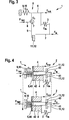
Die
Die Ersatzmodelle des Bremskraftverstärkers
Insbesondere beim Einsatz von sogenannten ”zero drag calipern” oder auch systembedingt kann es im Bereich des Bremssystems zu unerwünschten Leer- oder Todwegen kommen. Um diese zu kompensieren weist ein erfindungsgemäßer Bremskraftverstärker
Die Vorspanneinheit
Die Vorspanneinheit
Alternativ zu den dargestellten Ausführungsformen mit einer Reaktionseinheit
Die Funktionsweise eines erfindungsgemäßen Bremskraftverstärkers
Im oberen Teil von
Bei der dargestellten Ausführungsform ist zwischen dem ersten Teilelement
Wird im Vorfeld eines zu erwartenden Bremswunsches oder unmittelbar nach Erkennen eines Bremswunsches in einem Zeitbereich vor oder unmittelbar nach Erkennen einer Betätigung des Eingangselements
Speziell ist es möglich, sofern während der Todwegkompensation des zweite Teilelement
Wie bereits erwähnt wird erfindungsgemäß eine Unterstützungskraft Fsup im Vorfeld eines zu erwartenden Bremswunsches oder unmittelbar nach Erkennen eines Bremswunsches in einem Zeitbereich vor oder unmittelbar nach Erkennen einer Betätigung des Eingangselements erzeugt. Der genaue Zeitpunkt kann dabei auf vielfältige Weise festgelegt werden. So können beispielsweise ein Loslassen eines Gaspedals oder ein Ansprechen eines Bremslichtschalters oder auch ein Erkennen eines Schleppmomentes als Indizien für eine in Kürze zu erwartende Betätigung des Eingangselements des Bremskraftverstärkers interpretiert werden und damit als Trigger zur sukzessiven Erhöhung der Unterstützungskraft Fsup dienen.As already mentioned, according to the invention, an assisting force F sup is generated in advance of an expected braking request or immediately after detection of a braking request in a time range before or immediately after detecting an actuation of the input element. The exact time can be set in many ways. For example, a release of an accelerator pedal or a response of a brake light switch or a detection of a drag torque can be interpreted as indicia of a soon to be expected operation of the input element of the brake booster and thus serve as a trigger for successive increase of the support force F sup .
Alternativ zu der in
Claims (15)
Priority Applications (6)
| Application Number | Priority Date | Filing Date | Title |
|---|---|---|---|
| DE102010043202A DE102010043202A1 (en) | 2010-11-02 | 2010-11-02 | Brake booster and method for operating a brake booster |
| EP11752540.2A EP2635471B1 (en) | 2010-11-02 | 2011-09-05 | Brake booster and method for operating a brake booster |
| CN201180052805.5A CN103180182B (en) | 2010-11-02 | 2011-09-05 | Brake booster and the method for running brake booster |
| US13/880,816 US9868428B2 (en) | 2010-11-02 | 2011-09-05 | Brake booster and method for operating a brake booster |
| JP2013535326A JP5726313B2 (en) | 2010-11-02 | 2011-09-05 | Brake booster and method for driving a brake booster |
| PCT/EP2011/065246 WO2012059259A1 (en) | 2010-11-02 | 2011-09-05 | Brake booster and method for operating a brake booster |
Applications Claiming Priority (1)
| Application Number | Priority Date | Filing Date | Title |
|---|---|---|---|
| DE102010043202A DE102010043202A1 (en) | 2010-11-02 | 2010-11-02 | Brake booster and method for operating a brake booster |
Publications (1)
| Publication Number | Publication Date |
|---|---|
| DE102010043202A1 true DE102010043202A1 (en) | 2012-05-03 |
Family
ID=44583022
Family Applications (1)
| Application Number | Title | Priority Date | Filing Date |
|---|---|---|---|
| DE102010043202A Withdrawn DE102010043202A1 (en) | 2010-11-02 | 2010-11-02 | Brake booster and method for operating a brake booster |
Country Status (6)
| Country | Link |
|---|---|
| US (1) | US9868428B2 (en) |
| EP (1) | EP2635471B1 (en) |
| JP (1) | JP5726313B2 (en) |
| CN (1) | CN103180182B (en) |
| DE (1) | DE102010043202A1 (en) |
| WO (1) | WO2012059259A1 (en) |
Cited By (3)
| Publication number | Priority date | Publication date | Assignee | Title |
|---|---|---|---|---|
| FR3013658A1 (en) * | 2013-11-25 | 2015-05-29 | Renault Sa | BRAKING SYSTEM AND METHOD |
| WO2016034342A1 (en) * | 2014-09-01 | 2016-03-10 | Robert Bosch Gmbh | Brake booster for a brake system of a vehicle |
| CN105517864A (en) * | 2013-09-02 | 2016-04-20 | 罗伯特·博世有限公司 | Electromechanical brake booster for a brake system of a vehicle, and method for assembling an electromechanical brake booster on and/or in a brake system for a vehicle |
Families Citing this family (4)
| Publication number | Priority date | Publication date | Assignee | Title |
|---|---|---|---|---|
| DE102013200603A1 (en) | 2013-01-16 | 2014-07-31 | Robert Bosch Gmbh | Brake booster for brake system of vehicle i.e. car, has spring element clamped between stop element and fixed reference point device, so that dead way between stop element and point device is compensatable with pressing rod piston |
| DE112014002215T5 (en) * | 2013-04-30 | 2016-03-10 | Hitachi Automotive Systems, Ltd. | Electric amplifier |
| DE102017208685A1 (en) * | 2017-05-23 | 2018-11-29 | Robert Bosch Gmbh | Control device and method for operating an electromechanical brake booster of a vehicle |
| CN116215487B (en) * | 2023-05-08 | 2023-07-18 | 太原科技大学 | Polar all-terrain vehicle capable of intelligently monitoring braking torque on line |
Family Cites Families (14)
| Publication number | Priority date | Publication date | Assignee | Title |
|---|---|---|---|---|
| US3751919A (en) * | 1970-05-04 | 1973-08-14 | Shiber Samuel | Hydraulic power brake booster motor |
| DE19736997A1 (en) * | 1997-08-26 | 1999-03-04 | Bosch Gmbh Robert | Wheel brake game adjustment method e.g. for motor vehicles |
| FR2777851B1 (en) * | 1998-04-24 | 2000-06-09 | Bosch Syst Freinage | PNEUMATIC SERVOMOTOR WITH EFFORT CONTROLLED SELF-ASSISTANCE |
| JP4168220B2 (en) * | 1998-08-07 | 2008-10-22 | ボッシュ株式会社 | Automatic brake booster |
| US20060163941A1 (en) * | 2002-07-09 | 2006-07-27 | Von Hayn Holger | Brake by-wire actuator |
| DE102004024404B3 (en) * | 2004-05-17 | 2005-07-14 | Lucas Automotive Gmbh | Electromagnetic brake pressure creator for vehicle brake system has coupling components only able to be coupled after overcoming coupling play against spring |
| JP2006281992A (en) * | 2005-03-31 | 2006-10-19 | Hitachi Ltd | Electric booster |
| US7367187B2 (en) * | 2005-06-30 | 2008-05-06 | Hitachi, Ltd. | Electrically actuated brake booster |
| JP4692837B2 (en) * | 2005-06-30 | 2011-06-01 | 日立オートモティブシステムズ株式会社 | Electric booster |
| CN101945787B (en) * | 2007-12-21 | 2013-10-23 | 爱皮加特股份公司 | Brake system with adaptively controllable brake lining clearance and drive method thereof |
| FR2933936B1 (en) * | 2008-07-17 | 2014-10-10 | Bosch Gmbh Robert | ADJUSTABLE BRAKE ASSIST SERVOMOTOR |
| DE102008054856A1 (en) * | 2008-12-18 | 2010-07-01 | Robert Bosch Gmbh | Method for controlling a hydraulic vehicle brake system |
| DE102009045415A1 (en) * | 2009-10-07 | 2011-04-14 | Robert Bosch Gmbh | Method for operating a brake-boosted brake system of a vehicle and control device for a brake-boosted brake system of a vehicle |
| DE102010043203B4 (en) | 2010-11-02 | 2024-02-01 | Robert Bosch Gmbh | Brake booster and method for operating a brake booster |
-
2010
- 2010-11-02 DE DE102010043202A patent/DE102010043202A1/en not_active Withdrawn
-
2011
- 2011-09-05 WO PCT/EP2011/065246 patent/WO2012059259A1/en active Application Filing
- 2011-09-05 EP EP11752540.2A patent/EP2635471B1/en active Active
- 2011-09-05 CN CN201180052805.5A patent/CN103180182B/en active Active
- 2011-09-05 JP JP2013535326A patent/JP5726313B2/en active Active
- 2011-09-05 US US13/880,816 patent/US9868428B2/en active Active
Cited By (6)
| Publication number | Priority date | Publication date | Assignee | Title |
|---|---|---|---|---|
| CN105517864A (en) * | 2013-09-02 | 2016-04-20 | 罗伯特·博世有限公司 | Electromechanical brake booster for a brake system of a vehicle, and method for assembling an electromechanical brake booster on and/or in a brake system for a vehicle |
| CN105517864B (en) * | 2013-09-02 | 2018-08-17 | 罗伯特·博世有限公司 | Electric mechanical brake power amplifier and its assembly method for motor vehicle braking system |
| FR3013658A1 (en) * | 2013-11-25 | 2015-05-29 | Renault Sa | BRAKING SYSTEM AND METHOD |
| WO2015075268A3 (en) * | 2013-11-25 | 2015-09-24 | Renault S.A.S | Braking system and method |
| WO2016034342A1 (en) * | 2014-09-01 | 2016-03-10 | Robert Bosch Gmbh | Brake booster for a brake system of a vehicle |
| JP2017525611A (en) * | 2014-09-01 | 2017-09-07 | ローベルト ボッシュ ゲゼルシャフト ミット ベシュレンクテル ハフツング | Brake booster for vehicle brake system |
Also Published As
| Publication number | Publication date |
|---|---|
| US20130305706A1 (en) | 2013-11-21 |
| EP2635471B1 (en) | 2015-03-25 |
| US9868428B2 (en) | 2018-01-16 |
| CN103180182A (en) | 2013-06-26 |
| JP5726313B2 (en) | 2015-05-27 |
| WO2012059259A1 (en) | 2012-05-10 |
| JP2013540642A (en) | 2013-11-07 |
| CN103180182B (en) | 2015-12-16 |
| EP2635471A1 (en) | 2013-09-11 |
Similar Documents
| Publication | Publication Date | Title |
|---|---|---|
| DE102010043203B4 (en) | Brake booster and method for operating a brake booster | |
| EP2635471B1 (en) | Brake booster and method for operating a brake booster | |
| DE102009055639B4 (en) | braking system | |
| DE102010020002B4 (en) | Hydraulic assembly for a vehicle brake system | |
| EP2563630B1 (en) | Braking system for motor vehicles | |
| EP2467286B1 (en) | Master brake cylinder and method for operating a master brake cylinder | |
| DE102012217096B4 (en) | Brake booster and hydraulic brake system | |
| WO2014154631A2 (en) | Brake system for a vehicle | |
| EP3554901B1 (en) | Method for controlling a hydraulic brake system in a vehicle | |
| DE112014004292T5 (en) | braking means | |
| DE102014217445A1 (en) | Braking device for a motor vehicle and method for controlling the braking device | |
| DE102012025249A1 (en) | Electrohydraulic vehicle brake system and method for operating the same | |
| WO2012031718A2 (en) | Brake system having a connection, which can be switched by means of a brake pedal, for decoupling a drive device from a piston-cylinder unit | |
| DE102009027998A1 (en) | Hydraulic storage device and method for operating a hydraulic storage device | |
| DE102011085986A1 (en) | Brake assembly for motor car, has hydraulic chamber limited by cylinder piston and acted upon with pressure delivered by pressure provision device such that force effect is produced on cylinder piston in operation direction | |
| DE102010038918A1 (en) | Brake booster and method for its operation | |
| DE102012217092B4 (en) | Brake booster and hydraulic brake system | |
| WO2016184609A1 (en) | Electrohydraulic braking-force generation device for an electrohydraulic motor vehicle brake system | |
| DE112013007152T5 (en) | Vehicle brake device | |
| DE102011117264A1 (en) | Brake pedal simulator for brake-by-wire brake system of e.g. left-hand drive vehicle, has simulation device supported by piston that is arranged in hydraulic cylinder and fixed in predetermined starting position in normal operating mode | |
| EP2814701B1 (en) | Vehicle brake device, -system and -method | |
| EP2296948B1 (en) | Brake booster for an automotive brake system and corresponding automotive brake system | |
| DE102015211359A1 (en) | Preparation of a braking process in a motor vehicle | |
| DE102015210297B4 (en) | Motor vehicle with regenerative braking | |
| DE102019211236A1 (en) | Method for controlling a hydraulic brake system in a vehicle |
Legal Events
| Date | Code | Title | Description |
|---|---|---|---|
| R005 | Application deemed withdrawn due to failure to request examination |