EP2814701B1 - Vehicle brake device, -system and -method - Google Patents
Vehicle brake device, -system and -method Download PDFInfo
- Publication number
- EP2814701B1 EP2814701B1 EP12810200.1A EP12810200A EP2814701B1 EP 2814701 B1 EP2814701 B1 EP 2814701B1 EP 12810200 A EP12810200 A EP 12810200A EP 2814701 B1 EP2814701 B1 EP 2814701B1
- Authority
- EP
- European Patent Office
- Prior art keywords
- brake
- primary piston
- force
- component
- transmission component
- Prior art date
- Legal status (The legal status is an assumption and is not a legal conclusion. Google has not performed a legal analysis and makes no representation as to the accuracy of the status listed.)
- Active
Links
Images
Classifications
-
- B—PERFORMING OPERATIONS; TRANSPORTING
- B60—VEHICLES IN GENERAL
- B60T—VEHICLE BRAKE CONTROL SYSTEMS OR PARTS THEREOF; BRAKE CONTROL SYSTEMS OR PARTS THEREOF, IN GENERAL; ARRANGEMENT OF BRAKING ELEMENTS ON VEHICLES IN GENERAL; PORTABLE DEVICES FOR PREVENTING UNWANTED MOVEMENT OF VEHICLES; VEHICLE MODIFICATIONS TO FACILITATE COOLING OF BRAKES
- B60T13/00—Transmitting braking action from initiating means to ultimate brake actuator with power assistance or drive; Brake systems incorporating such transmitting means, e.g. air-pressure brake systems
- B60T13/10—Transmitting braking action from initiating means to ultimate brake actuator with power assistance or drive; Brake systems incorporating such transmitting means, e.g. air-pressure brake systems with fluid assistance, drive, or release
- B60T13/12—Transmitting braking action from initiating means to ultimate brake actuator with power assistance or drive; Brake systems incorporating such transmitting means, e.g. air-pressure brake systems with fluid assistance, drive, or release the fluid being liquid
- B60T13/14—Transmitting braking action from initiating means to ultimate brake actuator with power assistance or drive; Brake systems incorporating such transmitting means, e.g. air-pressure brake systems with fluid assistance, drive, or release the fluid being liquid using accumulators or reservoirs fed by pumps
- B60T13/142—Systems with master cylinder
-
- B—PERFORMING OPERATIONS; TRANSPORTING
- B60—VEHICLES IN GENERAL
- B60T—VEHICLE BRAKE CONTROL SYSTEMS OR PARTS THEREOF; BRAKE CONTROL SYSTEMS OR PARTS THEREOF, IN GENERAL; ARRANGEMENT OF BRAKING ELEMENTS ON VEHICLES IN GENERAL; PORTABLE DEVICES FOR PREVENTING UNWANTED MOVEMENT OF VEHICLES; VEHICLE MODIFICATIONS TO FACILITATE COOLING OF BRAKES
- B60T7/00—Brake-action initiating means
- B60T7/02—Brake-action initiating means for personal initiation
- B60T7/04—Brake-action initiating means for personal initiation foot actuated
- B60T7/042—Brake-action initiating means for personal initiation foot actuated by electrical means, e.g. using travel or force sensors
-
- B—PERFORMING OPERATIONS; TRANSPORTING
- B60—VEHICLES IN GENERAL
- B60T—VEHICLE BRAKE CONTROL SYSTEMS OR PARTS THEREOF; BRAKE CONTROL SYSTEMS OR PARTS THEREOF, IN GENERAL; ARRANGEMENT OF BRAKING ELEMENTS ON VEHICLES IN GENERAL; PORTABLE DEVICES FOR PREVENTING UNWANTED MOVEMENT OF VEHICLES; VEHICLE MODIFICATIONS TO FACILITATE COOLING OF BRAKES
- B60T11/00—Transmitting braking action from initiating means to ultimate brake actuator without power assistance or drive or where such assistance or drive is irrelevant
- B60T11/10—Transmitting braking action from initiating means to ultimate brake actuator without power assistance or drive or where such assistance or drive is irrelevant transmitting by fluid means, e.g. hydraulic
- B60T11/16—Master control, e.g. master cylinders
- B60T11/20—Tandem, side-by-side, or other multiple master cylinder units
- B60T11/203—Side-by-side configuration
-
- B—PERFORMING OPERATIONS; TRANSPORTING
- B60—VEHICLES IN GENERAL
- B60T—VEHICLE BRAKE CONTROL SYSTEMS OR PARTS THEREOF; BRAKE CONTROL SYSTEMS OR PARTS THEREOF, IN GENERAL; ARRANGEMENT OF BRAKING ELEMENTS ON VEHICLES IN GENERAL; PORTABLE DEVICES FOR PREVENTING UNWANTED MOVEMENT OF VEHICLES; VEHICLE MODIFICATIONS TO FACILITATE COOLING OF BRAKES
- B60T13/00—Transmitting braking action from initiating means to ultimate brake actuator with power assistance or drive; Brake systems incorporating such transmitting means, e.g. air-pressure brake systems
- B60T13/10—Transmitting braking action from initiating means to ultimate brake actuator with power assistance or drive; Brake systems incorporating such transmitting means, e.g. air-pressure brake systems with fluid assistance, drive, or release
- B60T13/58—Combined or convertible systems
- B60T13/588—Combined or convertible systems both fluid and mechanical assistance or drive
-
- B—PERFORMING OPERATIONS; TRANSPORTING
- B60—VEHICLES IN GENERAL
- B60T—VEHICLE BRAKE CONTROL SYSTEMS OR PARTS THEREOF; BRAKE CONTROL SYSTEMS OR PARTS THEREOF, IN GENERAL; ARRANGEMENT OF BRAKING ELEMENTS ON VEHICLES IN GENERAL; PORTABLE DEVICES FOR PREVENTING UNWANTED MOVEMENT OF VEHICLES; VEHICLE MODIFICATIONS TO FACILITATE COOLING OF BRAKES
- B60T13/00—Transmitting braking action from initiating means to ultimate brake actuator with power assistance or drive; Brake systems incorporating such transmitting means, e.g. air-pressure brake systems
- B60T13/74—Transmitting braking action from initiating means to ultimate brake actuator with power assistance or drive; Brake systems incorporating such transmitting means, e.g. air-pressure brake systems with electrical assistance or drive
- B60T13/745—Transmitting braking action from initiating means to ultimate brake actuator with power assistance or drive; Brake systems incorporating such transmitting means, e.g. air-pressure brake systems with electrical assistance or drive acting on a hydraulic system, e.g. a master cylinder
-
- B—PERFORMING OPERATIONS; TRANSPORTING
- B60—VEHICLES IN GENERAL
- B60T—VEHICLE BRAKE CONTROL SYSTEMS OR PARTS THEREOF; BRAKE CONTROL SYSTEMS OR PARTS THEREOF, IN GENERAL; ARRANGEMENT OF BRAKING ELEMENTS ON VEHICLES IN GENERAL; PORTABLE DEVICES FOR PREVENTING UNWANTED MOVEMENT OF VEHICLES; VEHICLE MODIFICATIONS TO FACILITATE COOLING OF BRAKES
- B60T8/00—Arrangements for adjusting wheel-braking force to meet varying vehicular or ground-surface conditions, e.g. limiting or varying distribution of braking force
- B60T8/32—Arrangements for adjusting wheel-braking force to meet varying vehicular or ground-surface conditions, e.g. limiting or varying distribution of braking force responsive to a speed condition, e.g. acceleration or deceleration
- B60T8/34—Arrangements for adjusting wheel-braking force to meet varying vehicular or ground-surface conditions, e.g. limiting or varying distribution of braking force responsive to a speed condition, e.g. acceleration or deceleration having a fluid pressure regulator responsive to a speed condition
- B60T8/38—Arrangements for adjusting wheel-braking force to meet varying vehicular or ground-surface conditions, e.g. limiting or varying distribution of braking force responsive to a speed condition, e.g. acceleration or deceleration having a fluid pressure regulator responsive to a speed condition including valve means of the relay or driver controlled type
Definitions
- the invention relates to a braking device for a vehicle. Furthermore, the invention relates to methods for operating a braking device of a vehicle.
- the master cylinder has a markable as a first piston rod piston and a tubular second piston.
- the first piston is slidable by a predetermined piston travel through the second piston into a first pressure chamber of the master cylinder.
- An entrainment device formed on the second piston is intended to cause the first piston, after overcoming the predetermined piston travel, to take along the second piston.
- the first piston and the second piston should be able to act on the first pressure chamber of the master cylinder after overcoming the predetermined piston travel together. In addition to be acted upon by means of a floating piston on a second pressure chamber of the master cylinder.
- the invention provides a braking device for a vehicle having the features of claim 1, a braking system having the features of claim 10, a method for operating a braking device of a vehicle having the features of claim 12 and a method for operating a braking device of a vehicle having the features of claim 15.
- a first idle travel between the force-free initial position of the brake force transmission component and the first primary piston component an effect of a driver braking force exerted on the brake actuating element / brake pedal can be reduced / prevented.
- This can also be described in such a way that, in spite of the driver braking force exerted on the brake actuating element, braking of the driver into the master brake cylinder can be easily reduced / prevented.
- a second free travel between the booster force transmission component present in its force-free initial position and the second primary piston component can prevent a booster force exerted on the booster force transmission component from automatically causing braking into the master brake cylinder.
- a Einbrems Koch of the force exerted by the actuator means on the amplifier power transmission component amplifier power can be reduced by the formation of the second idle travel.
- the brake power transmission component present in its force-free starting position can be spaced apart from the first primary piston component by the first idle travel which is greater than a distance between the booster force transmission component present in its force-free initial position and the second primary piston component.
- the distance between the booster force transmission component in its dead center position and the second primary piston member may be zero or nonzero.
- the present in their force-free initial position amplifier power transmission component to the second idle path not equal to zero the second primary piston component, which is greater than a distance between the present in their force-free initial position brake power transmission component and the first primary piston component.
- the distance between the braking force transmission component in its force-free starting position and the first primary piston component may be zero or non-zero in this case.
- an artificially extended idle travel can be formed between the booster force transmission component present in its force-free starting position and the second primary piston component, which can be used for recuperation, without this being associated with exceeding a setpoint deceleration of the vehicle specified by the driver.
- the brake device may have a fluid exchange device, through which in a first operating mode, a liquid between the first primary piston chamber and the second primary piston chamber is replaceable, and via which in the presence of the liquid exchange device in a second operating mode, a fluid exchange between the first primary piston chamber and the second primary piston chamber is prevented.
- a fluid exchange device By switching / controlling the liquid exchange device thus the primary Einbremsvolumen the master cylinder can be varied.
- the driver and the actuator device may brake into a total primary piston chamber of the first primary piston chamber and the second primary piston chamber with a larger total volume.
- the liquid exchange device by switching / controlling the liquid exchange device to the second mode of operation, it can be determined that only the driver enters the first primary piston chamber, i. H. in a primary Einbremsvolumen with only the first volume of the primary piston chamber, can brake.
- the switching / control of the liquid exchange device into the second operating mode is in particular in a mechanical fallback mode, i. H. in case of failure / functional impairment of the actuator device, advantageous.
- the master cylinder may additionally have a secondary piston chamber and one between the first primary piston chamber and the secondary piston chamber having adjustable secondary piston.
- the advantages of the present invention are therefore also applicable to a tandem master cylinder.
- the brake device in which at least the brake power transmission component present in its force-free starting position is spaced apart from the first primary piston component by the first idle travel, which can only be closed from a minimum driver brake force, can have an actuator control device by means of which the Aktor responded is controlled so that at a driver braking force under the minimum driver braking force a predetermined target amplifier power by the driven actuator so exercisable on the second primary piston component, that the second volume of the second primary piston chamber by means of the displaced second primary piston component reducible and a liquid transfer from the second Primary piston chamber in at least one wheel brake cylinder for establishing a form in the at least one wheel brake cylinder can be triggered.
- the brake device can have an actuator control device by means of which the Aktor diagnosed is controlled so that at a driver braking force under the minimum driver braking force a predetermined target amplifier power by the driven actuator so exercisable on the second primary piston component, that the second volume of the second primary piston chamber by means of the displaced second primary piston component reducible and a liquid transfer from the second Primary
- the actuator control device may additionally be designed to specify the desired amplifier power taking into account at least one state of a brake system component and / or a traffic situation.
- a pre-pressure in the at least one wheel brake cylinder can be established even before the driver directly brakes into the master brake cylinder.
- the desired amplifier power can be predetermined or be predeterminable by means of the actuator control device such that a clearance between at least one rest torque-free brake caliper and a brake disk can be closed by means of the established pre-pressure.
- the clearance between the at least one rest torque-free caliper and the cooperating brake disc can be closed in a simple manner by means of the established form. This leads to a significantly improved braking comfort for the driver.
- the brake device may have a generator control device, which at least at an amplifier power below the minimum amplifier power is designed to control a generator so that by means of the generator, a generator braking torque is equal to zero exercisable.
- the braking effect of the amplifier power which is prevented by means of the second idle travel, can thus be used for faster charging of a vehicle battery.
- the brake system can have at least one rest torque-free brake caliper. Since the clearance between the at least one brake caliper and the brake disk cooperating therewith can already be closed by means of building up a form even before the driver directly brakes by means of the driver braking force, the brake system can combine the advantages of good ease of use with reduced fuel consumption and lower pollutant emission.
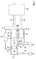
- Fig. 1 shows a schematic representation of a first embodiment of the braking device.
- FIG. 1 schematically illustrated brake device is in a vehicle, preferably in a vehicle equipped with a generator, used.
- the braking device may be arrangeable as a compact unit in a braking system of the vehicle.
- the brake device may be formed as a non-separated formed subunit of the brake system.
- the brake device has a master cylinder 10 with a first primary piston chamber 12, wherein a first volume of the first primary piston chamber 12 is variable by means of an adjustable first primary piston member 14.
- a braking force transmission component 16 of the braking device such as an output rod, can be arranged (directly or indirectly) on a (not shown) brake actuating element such that at least one driver braking force can be transmitted via the braking force transmission component 16 to the first adjustable primary piston component 14 contacted by the braking force transmission component 16.
- the brake operating element may be, for example, a brake pedal.
- the feasibility of the brake actuator or the braking force transmission component 16 is not limited to the here enumerated embodiments.
- the master cylinder 10 also has a second primary piston chamber 18 whose second volume is variable by means of an adjustable second primary piston component 20.
- the brake device also has an amplifier power transmission component 22, to which an actuator (not shown) can be arranged (directly or indirectly) such that an amplifier power provided by the actuator at least partially via the amplifier force transmission component 22 to the second adjustable primary piston component 20 contacted by the booster force transmission component 22 is transferable.
- the actuator device can be, for example, an engine and / or a hydraulic system of a brake booster.
- the first primary piston component 14 and / or the second primary piston component 20 may be formed, for example, as a rod piston component. It should be noted, however, that the formability of a primary piston member 14 and 20 is not limited to a rod piston. Likewise, the first primary piston component 14 and / or the second primary piston component 2 can each be constructed from a plurality of subcomponents. Also, the shape of the first primary piston member 14 and the second primary piston member 20 can be fixed with a large design freedom.
- the force-free starting position of the brake-force transmission component 16 can be understood to mean a position thereof in which the brake-force-transmitting component 16 is present when no driver braking force is transmitted to it.
- the force-free initial position of the booster force transmission component 22 is preferably to be understood as meaning a position thereof in which the booster force transmission component 22 is present at zero amplifier power or deactivation of the actuator device.
- the force-free initial positions of the power transmission components 16 and 22 are to be understood as positions in which the power transmission components 16 and 22 provided that no driver braking force is exerted on the brake actuator and no amplifier power is provided by means of the actuator device.
- the formation of the first idle path L1 not equal to zero has the advantage that, despite a driver braking force not equal to zero, which causes an adjustment of the braking force transmission component 16, a braking of the driver braking force in the master cylinder 10 is prevented up to a certain minimum driver braking force.
- a braking of the amplifier power in the master cylinder 10 is suppressed to a minimum amplifier power is exceeded. This can be exploited for a variety of advantageous uses, which will be described in more detail below.
- the brake power transfer component 16 may be in its zero-force starting position about a first non-zero Leerweg L1 of the first primary piston member 14, which is greater than a distance (zero or non-zero) between the booster force transmission component 22 in its force-free starting position and the second primary piston member 20 , As will be explained in more detail below, this allows the formation of a pre-pressure in the first primary piston chamber 12 even before a direct braking of the driver in the master cylinder 10th
- the booster force transmission component 22 may be in its non-energized starting position about a second non-zero L2 spaced from the second primary piston member 20 which is greater than zero (zero or non-zero) between the brake power transmission component 16 in its dead center position and the first primary piston member 14 is.
- a large second Leerweg L2 is associated with the advantage that, despite an amplifier power not equal to zero and at least slightly out of their force-free initial position adjusted amplifier power transmission component 22 no additional brake pressure is built up by adjusting the second primary piston member 20.
- the braking effect attributable to the persistence of the second primary piston component 20 in a position with a maximum second volume can be used to insert a generator without a vehicle deceleration predetermined by the driver is exceeded.
- a comparatively large second Leerweg L2 can be used for faster charging a vehicle battery.
- the first primary piston component 14 is still adjustable into the master cylinder 10 even in the presence of the actuator device in a deactivated / function-impaired state.
- the advantageous split design of the master cylinder 10 and the use of two primary piston components 14 and 20 is additionally associated with the advantage that when a functional impairment of the actuator / brake booster device by means of actuation of the brake actuator only the first primary piston member 14 is to move while the second primary piston member 20th remains in a certain position despite the operation of the brake actuator by the driver.
- the driver does not have to brake with the total braking surface equal to the sum of the boundary surfaces F1 + F2, but only with a reduced Einbrems Design equal to the first boundary surface F1, in the first primary piston chamber 12 of the master cylinder 10.
- the driver braking force causes a larger pressure build-up in the master brake cylinder 10.
- the functional impairment of Aktor worn / brake booster device due to the advantageous design of the master cylinder 10 and the use of two primary piston components 14 and 20 at least partially via an increased Einbremskraft-brake pressure transmission in a simple manner compensated.
- a secondary piston chamber 24 and between the first primary piston chamber 12 and the secondary piston chamber 24 adjustable secondary piston 26 have.
- the secondary piston 26 may be formed in particular as a floating piston.
- the first primary piston chamber 12, the second primary piston chamber 18 and / or the secondary piston chamber 24 may be connected via at least one brake fluid exchange port 28, such as a sniffer bore, to a brake fluid reservoir 30 / brake fluid reservoir.
- at least a partial partition wall 32 may be formed, which separates the first volume of the first primary piston chamber 12 from the second volume of the second primary piston chamber 18.
- each of the primary piston components 14 and 20 may be assigned its own opening 34 and 36.
- at least one sealing element such as a sealing ring, leakage of liquid can be prevented despite an adjustment of the respective primary piston component 14 and 20 from the respective opening 34 and 36.
- the braking device has a liquid exchange device 38, via which in the presence of the liquid exchange device 38 in a first operating mode, a liquid between the first primary piston chamber 12 and the second primary piston chamber 18 is interchangeable.
- the liquid exchange device 38 from the first operating mode at least in a second operating mode can be controlled / switched, wherein in the presence of the liquid exchange device 38 in the second mode of operation, a liquid exchange between the first primary piston chamber 12 and the second primary piston chamber 18 is prevented by means of the liquid exchange device 38.
- the liquid exchange device 38 may be, for example, a first brake circuit 38 with at least one wheel brake cylinder 40, to which the primary piston chambers 12 and 18 are connected.
- a (not shown) component of the first brake circuit 38 can be used.
- the secondary piston chamber 24 can also be connected to a second brake circuit 42 with at least one wheel brake cylinder 44.
- a valve formed in the partial partition wall 32 can also be used as the fluid exchange device 38.
- the brake device may have an amplifier body 46, which is arranged between the actuator device and the booster force transmission component 22 in such a way that the booster force can be transmitted via the booster body 46 to the booster force transmission component 22.
- the booster body 46 may also contact the brake power transmission component 16 in at least one position.
- at least a portion of the boosting force may also be transmitted via the brake power transfer component 16 to the first primary piston member 14 for assisting the rider in force when braking into the master cylinder 10. This ensures advantageous brake operation comfort for the driver.
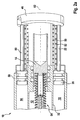
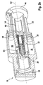
- Fig. 2a and 2 B show schematic partial views of a second embodiment of the braking device.
- FIG. 2a and 2 B schematically reproduced embodiment has the components already described above. On a more accurate marking of the first empty way and the second empty way is at the Fig. 2a and 2 B waived.
- Fig. 2a and 2 B are also cooperating with the brake force transmission component 16 first return spring 50, cooperating with the booster body 46 second return spring 52 and arranged in the first primary piston chamber 12 spring system 54, via which the first primary piston member 14 is supported on the secondary piston member 26 is shown.
- a third primary piston chamber 56 the third volume by means of an adjustable third primary piston member 58 is variable.
- a further amplifier power transmission component 60 at least part of the amplifier power can also be transmitted from the amplifier body 46 to the third primary piston component 58.
- the second primary piston chamber 18 and the third primary piston chamber 56 may in particular be formed symmetrically with respect to a central longitudinal axis 62 of the first primary piston chamber 12.
- the development of the master cylinder 10 described here is optional.
- the brake devices described in the above paragraphs may also have an actuator control device and / or a generator control device in an advantageous development.
- the interaction of the brake devices with the actuator control device is advantageous, provided that at least the present in their force-free initial position brake power transmission component 16 to the first idle path is not equal to zero spaced from the first primary piston member 14, which is closed only from a minimum driver brake force.
- the actuator control device is advantageous if the present in their force-free initial position brake power transmission component 16 by the first idle path is not equal to zero spaced from the first primary piston member 14, which is greater than a distance between the present in their force-free initial position booster force transmission component 22 and the second primary piston member 20th is.
- the actuator control device is designed so that by means of the actuator control device, the actuator device is controlled so that at a driver braking force under the minimum driver braking force a predetermined desired amplifier power by means of the driven actuator device so on the second primary piston component 20 is exercised that the second volume of the second primary piston chamber 18 can be reduced by means of the displaced second primary piston component 20, and a fluid transfer from the second primary piston chamber 18 into the at least one wheel brake cylinder can be triggered at least into the at least one wheel brake cylinder to build up a primary pressure.
- the actuator control device is additionally designed to specify the desired amplifier power taking into account at least one state of a brake system component and / or a traffic situation.
- the setpoint amplifier power can be predetermined by means of the actuator control device such that a clearance between at least one rest torque-free brake caliper and a brake disk can be closed by means of the established pre-pressure.
- the braking devices described above may in particular be a subunit of a brake system which Has at least one rest torque-free caliper.
- the interaction of the above-described brake devices with a generator control device is advantageous if at least the present in their force-free initial position amplifier power transmission component 22 by the second idle path is not equal to zero spaced from the second primary piston member 20, which is closed only from a minimum amplifier power.
- the generator control device is advantageous if the present in their force-free initial position booster force transmission component 22 by the second idle path is not equal to zero spaced from the second primary piston member 20, which is greater than a distance between the present in their force-free initial position brake power transmission component 16 and the first primary piston component fourteenth is.
- the generator control device is at least at an amplifier power below the minimum amplifier power designed to control a generator so that by means of the generator, a generator braking torque is equal to zero exercisable.
- the actuator control device and / or the generator control device may in particular be designed to carry out the functions explained using the methods described below.
- the operation of the actuator control device and the generator control device which may be integrated in particular in a common electronics, and the resulting advantages, reference is therefore made to the following methods.
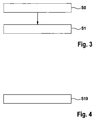
- Fig. 3 shows a flowchart for illustrating a first embodiment of the method for operating a braking device of a vehicle.
- That on the basis of Fig. 3 reproduced method is executable by means of a brake device with a master cylinder with a first primary piston chamber and a second primary piston chamber, a braking force transmission component, by means of which at least one driver brake force is transmitted to a first adjustable primary piston component contacted by the brake force transmission component such that a first volume of the first primary piston chamber is varied by means of the displaced first primary piston component, and an amplifier force transmission component with which an amplifier force provided by an actuator device at least partially so on the amplifier power transmission component contacted second adjustable primary piston component is transmitted, that a second volume of the second primary piston chamber is varied by means of the displaced second primary piston.
- the braking force transmission component is in its force-free starting position by a first idle path not equal to zero from the first primary piston component before, which is closed only from a minimum driver brake force.
- the method is also advantageous if the present in its force-free initial position brake power transmission component is present at the first free travel non-zero distance from the first primary piston component, which is greater than a distance between the present in their force-free initial position amplifier power transmission component and the second primary piston component.
- the method described here can be carried out, for example, by means of the braking devices described above. The feasibility of the method is not limited to a use of such a braking device.
- the method has at least one method step S1, in which an admission pressure is built up at least at least one wheel brake cylinder in spite of a driver braking force below the minimum driver braking force. This is done by applying a predetermined desired amplifier power by means of the actuator device.
- the at least partially transmitted to the second primary piston component target amplifier force causes a reduction of the second volume of the second primary piston chamber by means of the displaced second primary piston component and triggers a fluid transfer from the second primary piston chamber in the at least one wheel brake cylinder.
- an advantageous form in the at least one wheel brake cylinder is already at a start of a direct braking of the driver in the master cylinder.
- the method also has a method step S0, in which the desired amplifier power is predefined taking into account at least one state of a brake system component and / or a traffic situation.
- the desired amplifier power is predefined taking into account at least one state of a brake system component and / or a traffic situation.
- a traffic situation in which a rapid deceleration of the vehicle appears advantageous
- an advantageous pre-pressure can be built up even before a direct braking of the driver in the master cylinder.
- at least one state of a brake system component such as, for example, a functional impairment of a brake system component, may also be taken into account when specifying the desired amplifier power.
- the setpoint amplifier power is predetermined or fixed such that a clearance between at least one caliper, preferably a rest torque-free caliper, and a brake disc by means of the established form already before a direct braking of the driver in the Master cylinder is closed.
- a rest torque-free caliper has an increased clearance. You can also rewrite this so that no grinding of the pads of the caliper on the brake disc occurs in a rest torque-free caliper. In contrast occurs in a different caliper / non-residual torque caliper even when driving under non-actuation of the brake actuator, a grinding of the pads on the brake disc, which can cause a generally undesirable braking of the vehicle.
- the increased clearance of the rest torque-free caliper is associated with the advantage that no unwanted deceleration occurs during non-actuation of the brake actuator and thus driving the vehicle is already possible with a lower fuel consumption and a lower pollutant emission.
- a volume of the associated wheel brake cylinder which is necessary before a braking torque is effected, increased.
- a driver of a vehicle with restless calipers often has the impression of having a "long brake pedal," which is sometimes perceived as unsportsmanlike or uncomfortable. Therefore, many drivers reject the equipment of their vehicle with restless calipers despite the associated benefits in terms of lower fuel consumption and lower pollutant emissions.
- the construction of the admission pressure caused by the method step S1 causes a prefilling of the wheel brake cylinder, whereby the clearance can be overcome even before the driver directly brakes into the master brake cylinder.
- the driver of a vehicle the braking system is operated with the reproduced here method, thus has a normal brake feel / pedal feel even when equipped with rest torque-free calipers.
- the method described here thus combines the advantages of an advantageous brake feeling / pedal feeling with a reduced fuel consumption and a lower pollutant emission.
- Fig. 4 shows a flowchart for illustrating a second embodiment of the method for operating a braking device of a vehicle.
- the method can be carried out by means of a brake device with a master brake cylinder having a first primary piston chamber and a second primary piston chamber, a brake force transmission component, by means of which at least one driver brake force is transmitted to a contacted by the brake force transmission component first adjustable primary piston component so that a first volume of the first primary piston chamber by means of the displaced a booster force transmission component, by means of which an amplifier force provided by an actuator device is at least partially transmitted to a second variable primary piston component contacted by the booster force transmission component such that a second volume of the second primary piston chamber is varied by means of the displaced second primary piston component.
- At least the present in their force-free initial position amplifier power transmission component is spaced by a second idle path not equal to zero of the second primary piston component, which is closed only from a minimum amplifier power.
- the method is advantageous when the in its power-free initial position present amplifier power transmission component to the second idle path non-zero spaced from the second primary piston component is present, which is greater than a distance between the present in their force-free initial position brake power transmission component and the first primary piston component.
- the method described here can be carried out, for example, by means of the braking devices described above.
- the feasibility of the method is not limited to a use of such a braking device.
- the method has a method step S10, in which at least one amplifier power below the minimum amplifier power activates a generator for exerting a non-zero generator braking torque.
- the second free travel between the booster force transmission component and the second primary piston component can be used to reduce, in particular inhibit, a braking effect of the actuator device, and thus to use a generator for faster charging of a vehicle battery.
- the advantage is ensured that the driver can brake quickly and reliably directly into the master cylinder, and thus can cause a stoppage of the vehicle.
- the advantageous technology described in the above paragraphs enables a coupling of an operation of the actuator device and an actuation of the brake actuating element by the driver. At the same time, it is possible to decouple the driver from the braking system to a limited extent.
- blending between electric braking of a generator and hydraulic braking of a braking system equipped / operated with the advantageous technology is advantageously carried out.
- the blending may be performed so that the driver does not notice any difference between electric braking and hydraulic braking.
- an improvement of the fallback level can be achieved by freely setting a primary Einbremsvolumens at least between a total volume of the two primary piston chambers or only the first primary piston chamber, or the Einbrems formation.
Description
Die Erfindung betrifft ein Bremsgerät für ein Fahrzeug. Des Weiteren betrifft die Erfindung Verfahren zum Betreiben eines Bremsgeräts eines Fahrzeugs.The invention relates to a braking device for a vehicle. Furthermore, the invention relates to methods for operating a braking device of a vehicle.
In der
Die Erfindung schafft ein Bremsgerät für ein Fahrzeug mit den Merkmalen des Anspruchs 1, ein Bremssystem mit den Merkmalen des Anspruchs 10, ein Verfahren zum Betreiben eines Bremsgeräts eines Fahrzeugs mit den Merkmalen des Anspruchs 12 und ein Verfahren zum Betreiben eines Bremsgeräts eines Fahrzeugs mit den Merkmalen des Anspruchs 15.The invention provides a braking device for a vehicle having the features of
Durch die vorteilhafte Ausbildung eines ersten Leerwegs zwischen der kraftfreien Ausgangsstellung der Bremskraftübertragungskomponente und dem ersten Primärkolbenbauteil kann eine Wirkung einer auf das Bremsbetätigungselement/Bremspedal ausgeübten Fahrerbremskraft reduziert/unterbunden werden. Man kann dies auch so umschreiben, dass trotz der auf das Bremsbetätigungselement ausgeübten Fahrerbremskraft ein Einbremsen des Fahrers in den Hauptbremszylinder auf einfache Weise reduzierbar/verhinderbar ist. Ebenso kann durch einen zweiten Leerweg zwischen der in ihrer kraftfreien Ausgangsstellung vorliegenden Verstärkerkraftübertragungskomponente und dem zweiten Primärkolbenbauteil verhindert werden, dass eine auf die Verstärkerkraftübertragungskomponente ausgeübte Verstärkerkraft automatisch ein Einbremsen in den Hauptbremszylinder bewirkt. Außerdem kann eine Einbremswirkung der mittels der Aktoreinrichtung auf die Verstärkerkraftübertragungskomponente ausgeübten Verstärkerkraft durch das Ausbilden des zweiten Leerwegs reduziert werden.Due to the advantageous embodiment of a first idle travel between the force-free initial position of the brake force transmission component and the first primary piston component, an effect of a driver braking force exerted on the brake actuating element / brake pedal can be reduced / prevented. This can also be described in such a way that, in spite of the driver braking force exerted on the brake actuating element, braking of the driver into the master brake cylinder can be easily reduced / prevented. Likewise, a second free travel between the booster force transmission component present in its force-free initial position and the second primary piston component can prevent a booster force exerted on the booster force transmission component from automatically causing braking into the master brake cylinder. In addition, a Einbremswirkung of the force exerted by the actuator means on the amplifier power transmission component amplifier power can be reduced by the formation of the second idle travel.
Die in dem oberen Absatz beschriebenen Vorteile des ersten Leerwegs und/oder des zweiten Leerwegs können für eine Vielzahl von Nutzungsmöglichkeiten des erfindungsgemäßen Bremsgeräts ausgenutzt werden. Beispiele dazu werden in den folgenden Textstellen noch angegeben.The advantages of the first idle travel and / or the second idle travel described in the above paragraph can be utilized for a multiplicity of possible uses of the braking device according to the invention. Examples are given in the following passages.
Beispielsweise kann die in ihrer kraftfreien Ausgangsstellung vorliegende Bremskraftübertragungskomponente um den ersten Leerweg ungleich Null von dem ersten Primärkolbenbauteil beabstandet sein, welcher größer als ein Abstand zwischen der in ihrer kraftfreien Ausgangsstellung vorliegenden Verstärkerkraftübertragungskomponente und dem zweiten Primärkolbenbauteil ist. Der Abstand zwischen der Verstärkerkraftübertragungskomponente in ihrer kraftfreien Ausgangsstellung und dem zweiten Primärkolbenbauteil kann gleich Null oder ungleich Null sein. Somit kann bereits vor einem direkten Einbremsen des Fahrers in den Hauptbremszylinder ein Vordruck zumindest in der ersten Primärkolbenkammer aufgebaut werden. Wie unten genauer ausgeführt wird, kann somit bereits vor einem Einbremsen des Fahrers in den Hauptbremszylinder ein Lüftspiel geschlossen werden.For example, the brake power transmission component present in its force-free starting position can be spaced apart from the first primary piston component by the first idle travel which is greater than a distance between the booster force transmission component present in its force-free initial position and the second primary piston component. The distance between the booster force transmission component in its dead center position and the second primary piston member may be zero or nonzero. Thus, even before a direct braking of the driver in the master cylinder, a form at least in the first primary piston chamber are constructed. As will be explained in more detail below, a clearance can therefore be closed even before the driver brakes into the master brake cylinder.
Alternativ kann die in ihrer kraftfreien Ausgangsstellung vorliegende Verstärkerkraftübertragungskomponente um den zweiten Leerweg ungleich Null von dem zweiten Primärkolbenbauteil beabstandet sein, welcher größer als ein Abstand zwischen der in ihrer kraftfreien Ausgangsstellung vorliegenden Bremskraftübertragungskomponente und dem ersten Primärkolbenbauteil ist. Der Abstand zwischen der Bremskraftübertragungskomponente in ihrer kraftfreien Ausgangsstellung und dem ersten Primärkolbenbauteil kann in diesem Fall gleich Null oder ungleich Null sein. In beiden Fällen kann ein künstlich verlängerter Leerweg zwischen der in ihrer kraftfreien Ausgangsstellung vorliegenden Verstärkerkraftübertragungskomponente und dem zweiten Primärkolbenbauteil ausgebildet werden, welcher für eine Rekuperation nutzbar ist, ohne dass dies mit einem Überschreiten einer von dem Fahrer vorgegeben Soll-Verzögerung des Fahrzeugs verbunden ist.Alternatively, the present in their force-free initial position amplifier power transmission component to the second idle path not equal to zero the second primary piston component, which is greater than a distance between the present in their force-free initial position brake power transmission component and the first primary piston component. The distance between the braking force transmission component in its force-free starting position and the first primary piston component may be zero or non-zero in this case. In both cases, an artificially extended idle travel can be formed between the booster force transmission component present in its force-free starting position and the second primary piston component, which can be used for recuperation, without this being associated with exceeding a setpoint deceleration of the vehicle specified by the driver.
In einer vorteilhaften Weiterbildung kann das Bremsgerät eine Flüssigkeitsaustauscheinrichtung aufweisen, über welche bei einem Vorliegen der Flüssigkeitsaustauscheinrichtung in einem ersten Betriebsmodus eine Flüssigkeit zwischen der ersten Primärkolbenkammer und der zweiten Primärkolbenkammer austauschbar ist, und über welche bei einem Vorliegen der Flüssigkeitsaustauscheinrichtung in einem zweiten Betriebsmodus ein Flüssigkeitsaustausch zwischen der ersten Primärkolbenkammer und der zweiten Primärkolbenkammer unterbunden ist. Durch das Schalten/Ansteuern der Flüssigkeitsaustauscheinrichtung kann somit das primäre Einbremsvolumen des Hauptbremszylinders variiert werden. Beispielsweise kann durch das Schalten/Steuern der Flüssigkeitsaustauscheinrichtung in den ersten Betriebsmodus festgelegt werden, dass der Fahrer und die Aktoreinrichtung in eine Gesamt-Primärkolbenkammer aus der ersten Primärkolbenkammer und der zweiten Primärkolbenkammer mit einem größeren Gesamtvolumen einbremsen können. Demgegenüber kann durch ein Schalten/Steuern der Flüssigkeitsaustauscheinrichtung in den zweiten Betriebsmodus festgelegt werden, dass lediglich der Fahrer in die erste Primärkolbenkammer, d. h. in ein primäres Einbremsvolumen mit lediglich dem ersten Volumen der Primärkolbenkammer, einbremsen kann. Das Schalten/Steuern der Flüssigkeitsaustauscheinrichtung in den zweiten Betriebsmodus ist insbesondere in einer mechanischen Rückfallebene, d. h. bei einem Ausfall/einer Funktionsbeeinträchtigung der Aktoreinrichtung, vorteilhaft.In an advantageous development, the brake device may have a fluid exchange device, through which in a first operating mode, a liquid between the first primary piston chamber and the second primary piston chamber is replaceable, and via which in the presence of the liquid exchange device in a second operating mode, a fluid exchange between the first primary piston chamber and the second primary piston chamber is prevented. By switching / controlling the liquid exchange device thus the primary Einbremsvolumen the master cylinder can be varied. For example, by switching / controlling the fluid exchange device to the first mode of operation, it may be determined that the driver and the actuator device may brake into a total primary piston chamber of the first primary piston chamber and the second primary piston chamber with a larger total volume. In contrast, by switching / controlling the liquid exchange device to the second mode of operation, it can be determined that only the driver enters the first primary piston chamber, i. H. in a primary Einbremsvolumen with only the first volume of the primary piston chamber, can brake. The switching / control of the liquid exchange device into the second operating mode is in particular in a mechanical fallback mode, i. H. in case of failure / functional impairment of the actuator device, advantageous.
Außerdem kann der Hauptbremszylinder zusätzlich eine Sekundärkolbenkammer und einen zwischen der ersten Primärkolbenkammer und der Sekundärkolbenkammer verstellbaren Sekundärkolben aufweisen. Die Vorteile der vorliegenden Erfindung sind somit auch auf einen Tandemhauptbremszylinder anwendbar.In addition, the master cylinder may additionally have a secondary piston chamber and one between the first primary piston chamber and the secondary piston chamber having adjustable secondary piston. The advantages of the present invention are therefore also applicable to a tandem master cylinder.
In einer vorteilhaften Weiterbildung, in welcher zumindest die in ihrer kraftfreien Ausgangsstellung vorliegende Bremskraftübertragungskomponente um den ersten Leerweg ungleich Null von dem ersten Primärkolbenbauteil beabstandet ist, welcher erst ab einer Mindest-Fahrerbremskraft schließbar ist, kann das Bremsgerät eine Aktor-Steuervorrichtung aufweisen, mittels welcher die Aktoreinrichtung so ansteuerbar ist, dass bei einer Fahrerbremskraft unter der Mindest-Fahrerbremskraft eine vorgegebene Soll-Verstärkerkraft mittels der angesteuerten Aktoreinrichtung so auf das zweite Primärkolbenbauteil ausübbar ist, dass das zweite Volumen der zweiten Primärkolbenkammer mittels des verstellten zweiten Primärkolbenbauteils reduzierbar und ein Flüssigkeitstransfer von der zweiten Primärkolbenkammer in mindestens einen Radbremszylinder zum Aufbauen eines Vordrucks in dem mindestens einen Radbremszylinder auslösbar ist. Auf diese Weise ist gewährleistbar, dass bereits vor einem direkten Einbremsen des Fahrers in den Hauptbremszylinder ein vorteilhafter Vordruck in dem mindestens einen Radbremszylinder vorliegt.In an advantageous development, in which at least the brake power transmission component present in its force-free starting position is spaced apart from the first primary piston component by the first idle travel, which can only be closed from a minimum driver brake force, the brake device can have an actuator control device by means of which the Aktoreinrichtung is controlled so that at a driver braking force under the minimum driver braking force a predetermined target amplifier power by the driven actuator so exercisable on the second primary piston component, that the second volume of the second primary piston chamber by means of the displaced second primary piston component reducible and a liquid transfer from the second Primary piston chamber in at least one wheel brake cylinder for establishing a form in the at least one wheel brake cylinder can be triggered. In this way, it is possible to ensure that an advantageous admission pressure exists in the at least one wheel brake cylinder even before the driver directly brakes into the master brake cylinder.
Beispielsweise kann die Aktor-Steuervorrichtung zusätzlich dazu ausgelegt sein, die Soll-Verstärkerkraft unter Berücksichtigung mindestens eines Zustands einer Bremssystemkomponente und/oder einer Verkehrssituation vorzugeben. Somit kann bei einem Zustand der Bremssystemkomponente und/oder in einer Verkehrssituation, in welcher ein schnelles Abbremsen des Fahrzeugs vorteilhaft erscheint, schon vor einem direkten Einbremsen des Fahrers in den Hauptbremszylinder ein Vordruck in dem mindestens einen Radbremszylinder aufgebaut werden.For example, the actuator control device may additionally be designed to specify the desired amplifier power taking into account at least one state of a brake system component and / or a traffic situation. Thus, in the case of a state of the brake system component and / or in a traffic situation in which a rapid deceleration of the vehicle appears advantageous, a pre-pressure in the at least one wheel brake cylinder can be established even before the driver directly brakes into the master brake cylinder.
Außerdem kann die Soll-Verstärkerkraft so vorgegeben oder mittels der Aktor-Steuervorrichtung so vorgebbar sein, dass ein Lüftspiel zwischen mindestens einem restmomentfreien Bremssattel und einer Bremsscheibe mittels des aufgebauten Vordrucks schließbar ist. Während herkömmlicherweise viele Fahrer die Ausstattung ihres Bremssystems mit mindestens einem restmomentfreien Bremssattel trotz des damit verbundenen reduzierten Kraftstoffverbrauchs ablehnen, da das Schließen des Lüftspiels zwischen dem mindestens einen restmomentfreien Bremssattel und der damit zusammenwirkenden Bremsscheibe beim Stand der Technik zu einem verlängerten Bremsbetätigungsweg führt, kann bei der hier beschriebenen vorteilhaften Ausführungsform das Lüftspiel zwischen dem mindestens einen restmomentfreien Bremssattel und der damit zusammenwirkenden Bremsscheibe auf einfache Weise mittels des aufgebauten Vordrucks geschlossen werden. Dies führt zu einem deutlich verbesserten Bremskomfort für den Fahrer.In addition, the desired amplifier power can be predetermined or be predeterminable by means of the actuator control device such that a clearance between at least one rest torque-free brake caliper and a brake disk can be closed by means of the established pre-pressure. While traditionally many drivers reject the features of their braking system with at least one residual torque caliper despite the associated reduced fuel consumption, since the closing of the clearance between the at least one rest torque-free caliper and the cooperating brake disc In the prior art leads to a prolonged Bremsbetätigungsweg, in the advantageous embodiment described herein, the clearance between the at least one rest torque-free caliper and the cooperating brake disc can be closed in a simple manner by means of the established form. This leads to a significantly improved braking comfort for the driver.
In einer weiteren Weiterbildung, in welcher zumindest die in ihrer kraftfreien Ausgangsstellung vorliegende Verstärkerkraftübertragungskomponente um den zweiten Leerweg ungleich Null von dem zweiten Primärkolbenbauteil beabstandet ist, welcher erst ab einer Mindest-Verstärkerkraft schließbar ist, kann das Bremsgerät eine Generator-Steuervorrichtung aufweis3en, welche zumindest bei einer Verstärkerkraft unter der Mindest-Verstärkerkraft dazu ausgelegt ist, einen Generator so anzusteuern, dass mittels des Generators ein Generator-Bremsmoment ungleich Null ausübbar ist. Die mittels des zweiten Leerwegs unterbundene Bremswirkung der Verstärkerkraft kann somit zum schnelleren Aufladen einer Fahrzeugbatterie genutzt werden.In a further development, in which at least the present in their force-free initial position amplifier power transmission component to the second idle path is not equal to zero spaced from the second primary piston component, which is closed only from a minimum amplifier power, the brake device may have a generator control device, which at least at an amplifier power below the minimum amplifier power is designed to control a generator so that by means of the generator, a generator braking torque is equal to zero exercisable. The braking effect of the amplifier power, which is prevented by means of the second idle travel, can thus be used for faster charging of a vehicle battery.
Die in den oberen Absätzen beschriebenen Vorteile sind auch mittels eines Bremssystems mit einem entsprechenden Bremsgerät realisierbar.The advantages described in the upper paragraphs can also be realized by means of a braking system with a corresponding braking device.
Insbesondere kann das Bremssystem mindestens einen restmomentfreien Bremssattel aufweisen. Da mittels des Aufbauens eines Vordrucks bereits vor einem direkten Einbremsen des Fahrers mittels der Fahrerbremskraft das Lüftspiel zwischen dem mindestens einen Bremssattel und der damit zusammenwirkenden Bremsscheibe bereits schließbar ist, kann das Bremssystem die Vorteile eines guten Bedienkomforts mit einem reduzierten Kraftstoffverbrauch und einer geringeren Schadstoffemission vereinen.In particular, the brake system can have at least one rest torque-free brake caliper. Since the clearance between the at least one brake caliper and the brake disk cooperating therewith can already be closed by means of building up a form even before the driver directly brakes by means of the driver braking force, the brake system can combine the advantages of good ease of use with reduced fuel consumption and lower pollutant emission.
Die oben ausgeführten Vorteile sind auch bewirkbar durch Ausführen eines entsprechenden Verfahrens zum Betreiben eines Bremsgeräts eines Fahrzeugs.The advantages set out above can also be achieved by carrying out a corresponding method for operating a braking device of a vehicle.
Weitere Merkmale und Vorteile der vorliegenden Erfindung werden nachfolgend anhand der Figuren erläutert. Es zeigen:
- Fig. 1
- eine schematische Darstellung einer ersten Ausführungsform des Bremsgeräts;
- Fig. 2a und 2b
- schematische Teildarstellungen einer zweiten Ausführungsform des Bremsgeräts;
- Fig. 3
- ein Flussdiagramm zum Darstellen einer ersten Ausführungsform des Verfahrens zum Betreiben eines Bremsgeräts eines Fahrzeugs; und
- Fig. 4
- ein Flussdiagramm zum Darstellen einer zweiten Ausführungsform des Verfahrens zum Betreiben eines Bremsgeräts eines Fahrzeugs.
- Fig. 1
- a schematic representation of a first embodiment of the braking device;
- Fig. 2a and 2b
- schematic partial views of a second embodiment of the braking device;
- Fig. 3
- a flowchart for illustrating a first embodiment of the method for operating a braking device of a vehicle; and
- Fig. 4
- a flowchart for illustrating a second embodiment of the method for operating a braking device of a vehicle.
Das in
Das Bremsgerät weist einen Hauptbremszylinder 10 mit einer ersten Primärkolbenkammer 12 auf, wobei ein erstes Volumen der ersten Primärkolbenkammer 12 mittels eines verstellbaren ersten Primärkolbenbauteils 14 variierbar ist. Eine Bremskraftübertragungskomponente 16 des Bremsgeräts, wie beispielsweise eine Ausgangsstange, ist derart (direkt oder indirekt) an einem (nicht skizzierten) Bremsbetätigungselement anordbar, dass zumindest eine Fahrerbremskraft über die Bremskraftübertragungskomponente 16 auf das von der Bremskraftübertragungskomponente 16 kontaktierte erste verstellbare Primärkolbenbauteil 14 übertragbar ist. Das Bremsbetätigungselement kann beispielsweise ein Bremspedal sein. Die Ausbildbarkeit des Bremsbetätigungselements oder der Bremskraftübertragungskomponente 16 ist jedoch nicht auf die hier aufgezählten Ausführungsbeispiele beschränkt.The brake device has a
Der Hauptbremszylinder 10 hat auch eine zweite Primärkolbenkammer 18, deren zweites Volumen mittels eines verstellbaren zweiten Primärkolbenbauteils 20 variierbar ist. Das Bremsgerät weist außerdem eine Verstärkerkraftübertragungskomponente 22 auf, an welcher eine (nicht skizzierte) Aktoreinrichtung (direkt oder indirekt) derart anordbar ist, dass eine von der Aktoreinrichtung bereitgestellte Verstärkerkraft zumindest teilweise über die Verstärkerkraftübertragungskomponente 22 auf das von der Verstärkerkraftübertragungskomponente 22 kontaktierte zweite verstellbare Primärkolbenbauteil 20 übertragbar ist. Die Aktoreinrichtung kann beispielsweise ein Motor und/oder eine Hydraulik eines Bremskraftverstärkers sein.The
Das erste Primärkolbenbauteil 14 und/oder das zweite Primärkolbenbauteil 20 können beispielsweise als Stangenkolbenbauteil ausgebildet sein. Es wird jedoch darauf hingewiesen, dass die Ausbildbarkeit eines Primärkolbenbauteils 14 und 20 nicht auf einen Stangenkolben limitiert ist. Ebenso können das erste Primärkolbenbauteil 14 und/oder das zweite Primärkolbenbauteil 2 jeweils aus mehreren Unterkomponenten aufgebaut sein. Auch die Form des ersten Primärkolbenbauteils 14 und des zweiten Primärkolbenbauteils 20 ist mit einer großen Designfreiheit festlegbar.The first
Außerdem sind die in ihrer kraftfreien Ausgangsstellung vorliegende Bremskraftübertragungskomponente 16 um einen ersten Leerweg L1 ungleich Null von dem ersten Primärkolbenbauteil 14 beabstandet und/oder die in ihrer kraftfreien Ausgangsstellung vorliegende Verstärkerkraftübertragungskomponente 22 um einen zweiten Leerweg L2 ungleich Null von dem zweiten Primärkolbenbauteil 20 beabstandet. Unter der kraftfreien Ausgangsstellung der Bremskraftübertragungskomponente 16 kann beispielsweise eine Stellung von dieser verstanden werden, in welcher die Bremskraftübertragungskomponente 16 vorliegt, wenn keine Fahrerbremskraft auf sie übertragen wird. Entsprechend ist vorzugsweise unter der kraftfreien Ausgangsstellung der Verstärkerkraftübertragungskomponente 22 eine Stellung von dieser zu verstehen, in welcher die Verstärkerkraftübertragungskomponente 22 bei einer Verstärkerkraft gleich Null, bzw. bei einer Deaktivierung der Aktoreinrichtung, vorliegt. Bevorzugter Weise sind unter den kraftfreien Ausgangsstellungen der Kraftübertragungskomponenten 16 und 22 Stellungen zu verstehen, in welchen die Kraftübertragungskomponenten 16 und 22 vorliegen, sofern keine Fahrerbremskraft auf das Bremsbetätigungselement ausgeübt wird und keine Verstärkerkraft mittels der Aktoreinrichtung bereitgestellt wird.In addition, the present in their force-free initial position brake
Das Ausbilden des ersten Leerwegs L1 ungleich Null ist mit dem Vorteil verbunden, dass trotz einer Fahrerbremskraft ungleich Null, welche ein Verstellen der Bremskraftübertragungskomponente 16 bewirkt, ein Einbremsen der Fahrerbremskraft in den Hauptbremszylinder 10 bis zu einer bestimmten Mindest-Fahrerbremskraft verhindert ist. Ebenso ist mittels des zweiten Leerwegs L2 ungleich Null bewirkt, dass trotz einer Verstärkerkraft ungleich Null, welche eine Verstellung der Verstärkerkraftübertragungskomponente 22 auslöst, ein Einbremsen der Verstärkerkraft in den Hauptbremszylinder 10 bis zu einem Überschreiten einer Mindest-Verstärkerkraft unterbunden ist. Dies kann für eine Vielzahl von vorteilhaften Nutzungsmöglichkeiten ausgenutzt werden, welche unten noch genauer beschrieben werden.The formation of the first idle path L1 not equal to zero has the advantage that, despite a driver braking force not equal to zero, which causes an adjustment of the braking
Beispielsweise kann die Bremskraftübertragungskomponente 16 in ihrer kraftfreien Ausgangsstellung um einen ersten Leerweg L1 ungleich Null beabstandet von dem ersten Primärkolbenbauteil 14 vorliegen, welcher größer als ein Abstand (gleich Null oder ungleich Null) zwischen der Verstärkerkraftübertragungskomponente 22 in ihrer kraftfreien Ausgangsstellung und dem zweiten Primärkolbenbauteil 20 ist. Wie unten genauer ausgeführt wird, ermöglicht dies das Aufbauen eines Vordrucks in der ersten Primärkolbenkammer 12 bereits vor einem direkten Einbremsen des Fahrers in den Hauptbremszylinder 10.For example, the brake
Alternativ kann auch die Verstärkerkraftübertragungskomponente 22 in ihrer kraftfreien Ausgangsstellung um einen zweiten Leerweg L2 ungleich Null beabstandet von dem zweiten Primärkolbenbauteil 20 vorliegen, welcher größer als ein Abstand (gleich Null oder ungleich Null) zwischen der Bremskraftübertragungskomponente 16 in ihrer kraftfreien Ausgangsstellung und dem ersten Primärkolbenbauteil 14 ist. Ein großer zweiter Leerweg L2 ist mit dem Vorteil verbunden, dass trotz einer Verstärkerkraft ungleich Null und einer zumindest geringfügig aus ihrer kraftfreien Ausgangsstellung verstellten Verstärkerkraftübertragungskomponente 22 kein zusätzlicher Bremsdruck durch ein Verstellen des zweiten Primärkolbenbauteils 20 aufgebaut wird. Die durch das Verharren des zweiten Primärkolbenbauteils 20 in einer Stellung mit einem maximalen zweiten Volumen entfallende Bremswirkung kann zum Einsetzen eines Generators genutzt werden, ohne dass eine von dem Fahrer vorgegebene Fahrzeugverzögerung überschritten wird. Somit kann ein vergleichsweise großer zweiter Leerweg L2 für ein schnelleres Aufladen einer Fahrzeugbatterie genutzt werden.Alternatively, the booster
Bei der in
In einer vorteilhaften Weiterbildung kann der Hauptbremszylinder 10 zusätzlich eine Sekundärkolbenkammer 24 und einen zwischen der ersten Primärkolbenkammer 12 und der Sekundärkolbenkammer 24 verstellbaren Sekundärkolben 26 aufweisen. Der Sekundärkolben 26 kann insbesondere als Schwimmkolben ausgebildet sein. Die Vorteile eines Tandem-Hauptbremszylinder sind somit auch auf die hier beschriebene Ausbildungsform des Bremsgeräts anwendbar.In an advantageous development of the
Die erste Primärkolbenkammer 12, die zweite Primärkolbenkammer 18 und/oder die Sekundärkolbenkammer 24 können über mindestens eine Bremsflüssigkeitsaustauschöffnung 28, wie beispielsweise eine Schnüffelbohrung, mit einem Bremsflüssigkeitsreservoir 30/Bremsflüssigkeitsbehälter verbunden sein. Außerdem kann zwischen der ersten Primärkolbenkammer 12 und der zweiten Primärkolbenkammer 18 zumindest eine Teiltrennwand 32 ausgebildet sein, welche das erste Volumen der ersten Primärkolbenkammer 12 von dem zweiten Volumen der zweiten Primärkolbenkammer 18 abtrennt. Dies erleichtert die Ausstattung des Hauptbremszylinders 10 mit zwei Primärkolben 14 und 20, welche vorzugsweise durch mindestens eine äußere Öffnung 34 und 36 des Hauptbremszylinders 10 zumindest teilweise in die ihnen zugeordnete Primärkolbenkammer 12 und 18 hineinverstellbar sind. Beispielsweise kann jedem der Primärkolbenbauteile 14 und 20 eine eigene Öffnung 34 und 36 zugeordnet sein. Mittels mindestens eines Dichtelements, wie beispielsweise eines Dichtrings, kann ein Heraussickern von Flüssigkeit trotz eines Verstellens des jeweiligen Primärkolbenbauteils 14 und 20 aus der jeweiligen Öffnung 34 und 36 verhindert werden.The first
In einer vorteilhaften Weiterbildung weist das Bremsgerät eine Flüssigkeitsaustauscheinrichtung 38 auf, über welche bei einem Vorliegen der Flüssigkeitsaustauscheinrichtung 38 in einem ersten Betriebsmodus eine Flüssigkeit zwischen der ersten Primärkolbenkammer 12 und der zweiten Primärkolbenkammer 18 austauschbar ist. Außerdem kann die Flüssigkeitsaustauscheinrichtung 38 aus dem ersten Betriebsmodus zumindest in einen zweiten Betriebsmodus steuerbar/schaltbar sein, wobei bei einem Vorliegen der Flüssigkeitsaustauscheinrichtung 38 in dem zweiten Betriebsmodus ein Flüssigkeitsaustausch zwischen der ersten Primärkolbenkammer 12 und der zweiten Primärkolbenkammer 18 mittels der Flüssigkeitsaustauscheinrichtung 38 unterbunden ist. Die Flüssigkeitsaustauscheinrichtung 38 kann beispielsweise ein erster Bremskreis 38 mit mindestens einem Radbremszylinder 40 sein, an welchen die Primärkolbenkammern 12 und 18 angebunden sind. Zum Schalten/Steuern des ersten Bremskreises 38 zwischen den mindestens zwei Betriebsmoden kann eine (nicht skizzierte) Komponente des ersten Bremskreises 38 verwendet werden. (Optionaler Weise kann auch die Sekundärkolbenkammer 24 an einen zweiten Bremskreis 42 mit mindestens einem Radbremszylinder 44 angebunden sein.) Als Flüssigkeitsaustauscheinrichtung 38 kann jedoch auch ein in der Teiltrennwand 32 ausgebildetes Ventil verwendet werden. Auf eine besonders vorteilhafte Ausbildung des mindestens einen Radbremszylinders 40 und 44/Ausstattung des mindestens einen Bremskreises 38 und 42 wird unten noch eingegangen.In an advantageous development, the braking device has a
In einer weiteren Weiterbildung kann das Bremsgerät einen Verstärkerkörper 46 aufweisen, welcher derart zwischen der Aktoreinrichtung und der Verstärkerkraftübertragungskomponente 22 angeordnet ist, dass die Verstärkerkraft über den Verstärkerkörper 46 auf die Verstärkerkraftübertragungskomponente 22 übertragbar ist. Der Verstärkerkörper 46 kann außerdem in mindestens einer Stellung die Bremskraftübertragungskomponente 16 kontaktieren. Somit kann zumindest ein Teil der Verstärkerkraft auch über die Bremskraftübertragungskomponente 16 auf das erste Primärkolbenbauteil 14 zur kraftmäßigen Unterstützung des Fahrers bei einem Einbremsen in den Hauptbremszylinder 10 übertragen werden. Dies gewährleistet einen vorteilhaften Bremsbetätigungskomfort für den Fahrer.In a further development, the brake device may have an
Die in
Außerdem weist der Hauptbremszylinder 10 bei der dargestellten Ausführungsform noch eine dritte Primärkolbenkammer 56 auf, deren drittes Volumen mittels eines verstellbaren dritten Primärkolbenbauteils 58 variierbar ist. Über eine weitere Verstärkerkraftübertragungskomponente 60 kann zumindest ein Teil der Verstärkerkraft auch von dem Verstärkerkörper 46 auf das dritte Primärkolbenbauteil 58 übertragen werden. Somit ist der Vorteil der variierenden Einbremsfläche, welcher oben bereits ausgeführt wird, mittels einer Weiterbildung des Hauptbremszylinders 10 noch beliebig steigerbar. Die zweite Primärkolbenkammer 18 und die dritte Primärkolbenkammer 56 können insbesondere symmetrisch zueinander bezüglich einer Mittellängsachse 62 der ersten Primärkolbenkammer 12 ausgebildet sein. Die hier beschriebene Weiterbildung des Hauptbremszylinders 10 ist jedoch optional.In addition, the
Die in den oberen Absätzen beschriebenen Bremsgeräte können in einer vorteilhaften Weiterbildung auch eine Aktor-Steuervorrichtung und/oder eine Generator-Steuervorrichtung aufweisen. Das Zusammenwirken der Bremsgeräte mit der Aktor-Steuervorrichtung ist vorteilhaft, sofern zumindest die in ihrer kraftfreien Ausgangsstellung vorliegende Bremskraftübertragungskomponente 16 um den ersten Leerweg ungleich Null beabstandet von dem ersten Primärkolbenbauteil 14 vorliegt, welcher erst ab einer Mindest-Fahrerbremskraft schließbar ist. Insbesondere ist die Aktor-Steuervorrichtung vorteilhaft, wenn die in ihrer kraftfreien Ausgangsstellung vorliegende Bremskraftübertragungskomponente 16 um den ersten Leerweg ungleich Null beabstandet von dem ersten Primärkolbenbauteil 14 vorliegt, welcher größer als ein Abstand zwischen der in ihrer kraftfreien Ausgangsstellung vorliegenden Verstärkerkraftübertragungskomponente 22 und dem zweiten Primärkolbenbauteil 20 ist. Bevorzugter Weise ist die Aktor-Steuervorrichtung so ausgelegt, dass mittels der Aktor-Steuervorrichtung die Aktoreinrichtung so ansteuerbar ist, dass bei einer Fahrerbremskraft unter der Mindest-Fahrerbremskraft eine vorgegebene Soll-Verstärkerkraft mittels der angesteuerten Aktoreinrichtung so auf das zweiten Primärkolbenbauteil 20 ausübbar ist, dass das zweite Volumen der zweiten Primärkolbenkammer 18 mittels des verstellten zweiten Primärkolbenbauteils 20 reduzierbar und ein Flüssigkeitstransfer von der zweiten Primärkolbenkammer 18 in die mindestens einen Radbremszylinder zum Aufbauen eines Vordrucks zumindest in den mindestens einen Radbremszylinder auslösbar ist.The brake devices described in the above paragraphs may also have an actuator control device and / or a generator control device in an advantageous development. The interaction of the brake devices with the actuator control device is advantageous, provided that at least the present in their force-free initial position brake
Vorteilhafter Weise ist die Aktor-Steuervorrichtung zusätzlich dazu ausgelegt, die Soll-Verstärkerkraft unter Berücksichtigung mindestens eines Zustands einer Bremssystemkomponente und/oder einer Verkehrssituation vorzugeben. Insbesondere kann die Soll-Verstärkerkraft mittels der Aktor-Steuervorrichtung so vorgebbar sein, dass ein Lüftspiel zwischen mindestens einem restmomentfreien Bremssattel und einer Bremsscheibe mittels des aufgebauten Vordrucks schließbar ist. Die oben beschriebenen Bremsgeräte können insbesondere eine Untereinheit eines Bremssystems sein, welches mindestens einen restmomentfreien Bremssattel aufweist. Da die oben ausgeführten Bremsgeräte auf einfache Weise so betreibbar sind, dass bereits vor einem direkten Einbremsen ein Lüftspiel zwischen dem mindestens einen restmomentfreien Bremssattel und einer Bremsscheibe geschlossen werden kann, gewährleistet ein derartiges Bremssystem die Vorteile eines vorteilhaften Bremskomforts für den Fahrer bei einem reduzierten Kraftstoffverbrauch und einer geringeren Schadstoffemission.Advantageously, the actuator control device is additionally designed to specify the desired amplifier power taking into account at least one state of a brake system component and / or a traffic situation. In particular, the setpoint amplifier power can be predetermined by means of the actuator control device such that a clearance between at least one rest torque-free brake caliper and a brake disk can be closed by means of the established pre-pressure. The braking devices described above may in particular be a subunit of a brake system which Has at least one rest torque-free caliper. Since the above-mentioned braking devices are easily operable so that even before a direct braking a clearance between the at least one residual torque caliper and a brake disc can be closed, such a brake system ensures the benefits of advantageous braking comfort for the driver with a reduced fuel consumption and a lower pollutant emission.
Das Zusammenwirken der oben beschriebenen Bremsgeräte mit einer Generator-Steuervorrichtung ist vorteilhaft, sofern zumindest die in ihrer kraftfreien Ausgangsstellung vorliegende Verstärkerkraftübertragungskomponente 22 um den zweiten Leerweg ungleich Null beabstandet von dem zweiten Primärkolbenbauteil 20 vorliegt, welcher erst ab einer Mindest-Verstärkerkraft schließbar ist. Insbesondere ist die Generator-Steuervorrichtung vorteilhaft, wenn die in ihrer kraftfreien Ausgangsstellung vorliegende Verstärkerkraftübertragungskomponente 22 um den zweiten Leerweg ungleich Null beabstandet von dem zweiten Primärkolbenbauteil 20 vorliegt, welcher größer als ein Abstand zwischen der in ihrer kraftfreien Ausgangsstellung vorliegenden Bremskraftübertragungskomponente 16 und dem ersten Primärkolbenbauteil 14 ist. Vorteilhafterweise ist die Generator-Steuervorrichtung zumindest bei einer Verstärkerkraft unter der Mindest-Verstärkerkraft dazu ausgelegt, einen Generator so anzusteuern, dass mittels des Generators ein Generator-Bremsmoment ungleich Null ausübbar ist.The interaction of the above-described brake devices with a generator control device is advantageous if at least the present in their force-free initial position amplifier
Die Aktor-Steuervorrichtung und/oder die Generator-Steuervorrichtung können insbesondere dazu ausgelegt sein, die anhand der nachfolgend beschriebenen Verfahren erläuterten Funktionen auszuführen. Bezüglich der Funktionsweise der Aktor-Steuervorrichtung und der Generator-Steuervorrichtung, welche insbesondere in eine gemeinsame Elektronik integriert sein können, und der sich daraus ergebenden Vorteile wird deshalb auf die nachfolgenden Verfahren verwiesen.The actuator control device and / or the generator control device may in particular be designed to carry out the functions explained using the methods described below. Regarding the operation of the actuator control device and the generator control device, which may be integrated in particular in a common electronics, and the resulting advantages, reference is therefore made to the following methods.
Das anhand der
Das Verfahren weist zumindest einen Verfahrensschritt S1 auf, in welchem ein Vordruck zumindest mindestens einen Radbremszylinder bei/trotz einer Fahrerbremskraft unter der Mindest-Fahrerbremskraft aufgebaut wird. Dies erfolgt durch Ausüben einer vorgegebenen Soll-Verstärkerkraft mittels der Aktoreinrichtung. Die zumindest teilweise auf das zweite Primärkolbenbauteil übertragene Soll-Verstärkerkraft bewirkt eine Reduzierung des zweiten Volumens der zweiten Primärkolbenkammer mittels des verstellten zweiten Primärkolbenbauteils und löst einen Flüssigkeitstransfer von der zweiten Primärkolbenkammer in den mindestens einen Radbremszylinder aus. Somit liegt bereits bei einem Beginn eines direkten Einbremsens des Fahrers in den Hauptbremszylinder ein vorteilhafter Vordruck in dem mindestens einen Radbremszylinder vor.The method has at least one method step S1, in which an admission pressure is built up at least at least one wheel brake cylinder in spite of a driver braking force below the minimum driver braking force. This is done by applying a predetermined desired amplifier power by means of the actuator device. The at least partially transmitted to the second primary piston component target amplifier force causes a reduction of the second volume of the second primary piston chamber by means of the displaced second primary piston component and triggers a fluid transfer from the second primary piston chamber in the at least one wheel brake cylinder. Thus, an advantageous form in the at least one wheel brake cylinder is already at a start of a direct braking of the driver in the master cylinder.
Optionalerweise weist das Verfahren auch einen Verfahrensschritt S0 auf, in welchem die Soll-Verstärkerkraft unter Berücksichtigung mindestens eines Zustands einer Bremssystemkomponente und/oder einer Verkehrssituation vorgeben wird. Beispielsweise kann nach einem Erkennen einer Verkehrssituation, in welcher ein schnelles Abbremsen des Fahrzeugs vorteilhaft erscheint, bereits vor einem direkten Einbremsen des Fahrers in den Hauptbremszylinder ein vorteilhafter Vordruck aufgebaut werden. Alternativ oder ergänzend kann auch mindestens ein Zustand einer Bremssystemkomponente, wie beispielsweise eine Funktionsbeeinträchtigung einer Bremssystemkomponente, beim Festlegen der Soll-Verstärkerkraft berücksichtigt werden.Optionally, the method also has a method step S0, in which the desired amplifier power is predefined taking into account at least one state of a brake system component and / or a traffic situation. For example, after a detection of a traffic situation in which a rapid deceleration of the vehicle appears advantageous, an advantageous pre-pressure can be built up even before a direct braking of the driver in the master cylinder. Alternatively or additionally, at least one state of a brake system component, such as, for example, a functional impairment of a brake system component, may also be taken into account when specifying the desired amplifier power.
In einer vorteilhaften Ausführungsform des Verfahrens wird die Soll-Verstärkerkraft so (fest/konstant) vorgegeben oder festgelegt, dass ein Lüftspiel zwischen mindestens einem Bremssattel, vorzugsweise einem restmomentfreien Bremssattel, und einer Bremsscheibe mittels des aufgebauten Vordrucks bereits vor einem direkten Einbremsen des Fahrers in den Hauptbremszylinder geschlossen wird. Ein restmomentfreier Bremssattel verfügt über ein erhöhtes Lüftspiel. Man kann dies auch so umschreiben, dass bei einem restmomentfreien Bremssattel kein Schleifen der Beläge des Bremssattels an der Bremsscheibe auftritt. Demgegenüber tritt bei einem andersartigen Bremssattel/nicht-restmomentfreien Bremssattel selbst bei einer Fahrt unter Nichtbetätigung des Bremsbetätigungselements ein Schleifen der Beläge an der Bremsscheibe auf, welches ein in der Regel unerwünschtes Abbremsen des Fahrzeugs bewirken kann. Dieses unerwünschte Abbremsen aufgrund des Schleifens der Beläge eines nichtrestmomentfreien Bremssattels muss deshalb in der Regel durch eine zusätzliche Beschleunigung des Fahrzeugs kompensiert werden, wodurch herkömmlicherweise ein Kraftstoffverbrauch und eine Schadstoffemission während der Fahrt unter Nichtbetätigung des Bremsbetätigungselements erhöht werden.In an advantageous embodiment of the method, the setpoint amplifier power is predetermined or fixed such that a clearance between at least one caliper, preferably a rest torque-free caliper, and a brake disc by means of the established form already before a direct braking of the driver in the Master cylinder is closed. A rest torque-free caliper has an increased clearance. You can also rewrite this so that no grinding of the pads of the caliper on the brake disc occurs in a rest torque-free caliper. In contrast occurs in a different caliper / non-residual torque caliper even when driving under non-actuation of the brake actuator, a grinding of the pads on the brake disc, which can cause a generally undesirable braking of the vehicle. Therefore, this undesirable deceleration due to the grinding of the pads of a non-residual torque caliper must be compensated usually by an additional acceleration of the vehicle, thereby conventionally fuel consumption and pollutant emission while driving under non-operation of the brake actuator are increased.
Demgegenüber ist das erhöhte Lüftspiel des restmomentfreien Bremssattels mit dem Vorteil verbunden, dass keine unerwünschte Abbremsung während einer Nichtbetätigung des Bremsbetätigungselements erfolgt und somit eine Fahrt des Fahrzeugs bereits bei einem geringeren Kraftstoffverbrauch und einer niedrigeren Schadstoffemission möglich ist. Durch das Lüftspiel wird jedoch eine Volumenaufnahme des zugeordneten Radbremszylinders, welche notwendig ist, bevor ein Bremsmoment bewirkt wird, erhöht. Herkömmlicherweise hat deshalb ein Fahrer eines Fahrzeugs mit restmomentfreien Bremssätteln oft den Eindruck, ein "langes Bremspedal" zu haben, was manchmal als unsportlich oder unangenehm empfunden wird. Deshalb lehnen viele Fahrer die Ausstattung ihres Fahrzeugs mit restmomentfreien Bremssätteln trotz der damit verbundenen Vorteile hinsichtlich des geringeren Kraftstoffverbrauchs und der niedrigeren Schadstoffemission ab.In contrast, the increased clearance of the rest torque-free caliper is associated with the advantage that no unwanted deceleration occurs during non-actuation of the brake actuator and thus driving the vehicle is already possible with a lower fuel consumption and a lower pollutant emission. By the clearance, however, a volume of the associated wheel brake cylinder, which is necessary before a braking torque is effected, increased. Conventionally, therefore, a driver of a vehicle with restless calipers often has the impression of having a "long brake pedal," which is sometimes perceived as unsportsmanlike or uncomfortable. Therefore, many drivers reject the equipment of their vehicle with restless calipers despite the associated benefits in terms of lower fuel consumption and lower pollutant emissions.
Das durch den Verfahrensschritt S1 bewirkte Aufbauen des Vordrucks bewirkt jedoch ein Vorbefüllen des Radbremszylinders, wodurch bereits vor einem direkten Einbremsen des Fahrers in den Hauptbremszylinder das Lüftspiel überwunden werden kann. Der Fahrer eines Fahrzeugs, dessen Bremssystem mit dem hier wiedergegebenen Verfahren betrieben wird, hat somit auch bei einer Ausstattung mit restmomentfreien Bremssätteln ein normales Bremsgefühl/Pedalgefühl. Das hier beschriebene Verfahren kombiniert somit die Vorteile eines vorteilhaften Bremsgefühls/Pedalgefühls mit einem reduzierten Kraftstoffverbrauch und einer geringeren Schadstoffemission.However, the construction of the admission pressure caused by the method step S1 causes a prefilling of the wheel brake cylinder, whereby the clearance can be overcome even before the driver directly brakes into the master brake cylinder. The driver of a vehicle, the braking system is operated with the reproduced here method, thus has a normal brake feel / pedal feel even when equipped with rest torque-free calipers. The method described here thus combines the advantages of an advantageous brake feeling / pedal feeling with a reduced fuel consumption and a lower pollutant emission.
Insbesondere erhöhte Lüftspiele können mittels des hier beschriebenen Verfahrens kompensiert werden. Durch das dadurch bewirkte Vorbefüllen hat der Fahrer in jedem Fall einen kürzeren Bremsbetätigungsweg/Pedalweg. Außerdem ist das Anwenden des hier beschriebenen Verfahrens mit der oben schon beschriebenen verbesserten mechanischen Rückfallebene, beispielsweise bei einer Funktionsbeeinträchtigung mindestens einer Bremssystemkomponente, wie insbesondere der als Bremskraftverstärker genutzten Aktoreinrichtung, kombinierbar.In particular, increased clearances can be compensated by means of the method described here. Due to the pre-filling caused thereby, the driver has a shorter Bremsbetätigungsweg / pedal travel in each case. In addition, the application of the method described here with the above-described improved mechanical fallback level, for example in a functional impairment of at least one brake system component, such as in particular used as a brake booster actuator device, combined.
Das Verfahren ist ausführbar mittels eines Bremsgeräts mit einem Hauptbremszylinder mit einer ersten Primärkolbenkammer und einer zweiten Primärkolbenkammer, einer Bremskraftübertragungskomponente, mittels welcher zumindest eine Fahrerbremskraft auf ein von der Bremskraftübertragungskomponente kontaktiertes erstes verstellbares Primärkolbenbauteil so übertragen wird, dass ein erstes Volumen der ersten Primärkolbenkammer mittels des verstellten ersten Primärkolbenbauteils variiert wird, und einer Verstärkerkraftübertragungskomponente, mittels welcher eine von einer Aktoreinrichtung bereitgestellte Verstärkerkraft zumindest teilweise so auf ein von der Verstärkerkraftübertragungskomponente kontaktiertes zweites verstellbares Primärkolbenbauteil übertragen wird, dass ein zweites Volumen der zweiten Primärkolbenkammer mittels des verstellten zweiten Primärkolbenbauteils variiert wird. Zumindest die in ihrer kraftfreien Ausgangsstellung vorliegende Verstärkerkraftübertragungskomponente ist um einen zweiten Leerweg ungleich Null von dem zweiten Primärkolbenbauteil beabstandet, welcher erst ab einer Mindest-Verstärkerkraft geschlossen wird. Außerdem ist das Verfahren vorteilhaft, wenn die in ihrer kraftfreien Ausgangsstellung vorliegende Verstärkerkraftübertragungskomponente um den zweiten Leerweg ungleich Null beabstandet von dem zweiten Primärkolbenbauteil vorliegt, welcher größer als ein Abstand zwischen der in ihrer kraftfreien Ausgangsstellung vorliegenden Bremskraftübertragungskomponente und dem ersten Primärkolbenbauteil ist.The method can be carried out by means of a brake device with a master brake cylinder having a first primary piston chamber and a second primary piston chamber, a brake force transmission component, by means of which at least one driver brake force is transmitted to a contacted by the brake force transmission component first adjustable primary piston component so that a first volume of the first primary piston chamber by means of the displaced a booster force transmission component, by means of which an amplifier force provided by an actuator device is at least partially transmitted to a second variable primary piston component contacted by the booster force transmission component such that a second volume of the second primary piston chamber is varied by means of the displaced second primary piston component. At least the present in their force-free initial position amplifier power transmission component is spaced by a second idle path not equal to zero of the second primary piston component, which is closed only from a minimum amplifier power. Moreover, the method is advantageous when the in its power-free initial position present amplifier power transmission component to the second idle path non-zero spaced from the second primary piston component is present, which is greater than a distance between the present in their force-free initial position brake power transmission component and the first primary piston component.
Das hier beschriebene Verfahren ist beispielsweise mittels der oben beschriebenen Bremsgeräte ausführbar. Die Ausführbarkeit des Verfahrens ist jedoch nicht auf eine Verwendung eines derartigen Bremsgeräts limitiert.The method described here can be carried out, for example, by means of the braking devices described above. The feasibility of the method is not limited to a use of such a braking device.
Das Verfahren weist einen Verfahrensschritt S10 auf, in welchem zumindest bei einer Verstärkerkraft unter der Mindest-Verstärkerkraft ein Generator zum Ausüben eines Generator-Bremsmoments ungleich Null aktiviert wird. Somit kann der zweite Leerweg zwischen der Verstärkerkraftübertragungskomponente und dem zweiten Primärkolbenbauteil dazu genutzt werden, eine Bremswirkung der Aktoreinrichtung zu reduzieren, insbesondere zu unterbinden, und somit einen Generator zum schnelleren Aufladen einer Fahrzeugbatterie zu nutzen. Gleichzeitig ist in der oben schon beschriebenen Rückfallebene der Vorteil gewährleistet, dass der Fahrer schnell und zuverlässig direkt in den Hauptbremszylinder hineinbremsen kann, und somit einen Stillstand des Fahrzeugs bewirken kann.The method has a method step S10, in which at least one amplifier power below the minimum amplifier power activates a generator for exerting a non-zero generator braking torque. Thus, the second free travel between the booster force transmission component and the second primary piston component can be used to reduce, in particular inhibit, a braking effect of the actuator device, and thus to use a generator for faster charging of a vehicle battery. At the same time in the fallback level already described above, the advantage is ensured that the driver can brake quickly and reliably directly into the master cylinder, and thus can cause a stoppage of the vehicle.
Die in den oberen Absätzen beschriebene vorteilhafte Technologie ermöglicht eine Kopplung eines Betriebs der Aktoreinrichtung und einer Betätigung des Bremsbetätigungselements durch den Fahrer. Gleichzeitig ist es möglich, dem Fahrer im eingeschränkten Rahmen von dem Bremssystem zu entkoppeln. Ebenso ist ein Verblenden zwischen einem elektrischen Bremsen eines Generators und einem hydraulischen Bremsen eines mit der vorteilhaften Technologie ausgestatteten/betriebenen Bremssystems vorteilhaft ausführbar. Das Verblenden kann insbesondere so ausgeführt werden, dass der Fahrer keinen Unterschied zwischen einem elektrischen Bremsen und einem hydraulischen Bremsen bemerkt. Gleichzeitig kann durch das freie Einstellen eines primären Einbremsvolumens zumindest zwischen einem Gesamtvolumen der beiden Primärkolbenkammern oder lediglich der ersten Primärkolbenkammer, bzw. der Einbremsfläche, eine Verbesserung der Rückfallebene erreicht werden.The advantageous technology described in the above paragraphs enables a coupling of an operation of the actuator device and an actuation of the brake actuating element by the driver. At the same time, it is possible to decouple the driver from the braking system to a limited extent. Likewise, blending between electric braking of a generator and hydraulic braking of a braking system equipped / operated with the advantageous technology is advantageously carried out. In particular, the blending may be performed so that the driver does not notice any difference between electric braking and hydraulic braking. At the same time an improvement of the fallback level can be achieved by freely setting a primary Einbremsvolumens at least between a total volume of the two primary piston chambers or only the first primary piston chamber, or the Einbremsfläche.
Claims (15)
- Brake device for a vehicle having:a brake master cylinder (10) with a first primary piston chamber (12), the first volume of which can be varied by means of an adjustable first primary piston component (14);a brake force transmission component (16), on which a brake actuating element can be arranged directly or indirectly in such a way that at least a driver brake force can be transmitted via the brake force transmission component (16) to the adjustable first primary piston component (14) which is contacted by the brake force transmission component (16); andan adjustable second primary piston component (20) ;characterized in thatthe brake master cylinder (10) has a second primary piston chamber (18), the second volume of which can be varied by means of the adjustable second primary piston component (20);the brake device having a booster force transmission component (22), on which an actuator device can be arranged directly or indirectly in such a way that a booster force which is provided by the actuator device can be transmitted at least partially via the booster force transmission component (22) to the adjustable second primary piston component (20) which is contacted by the booster force transmission component (22); andthe brake force transmission component (16) which is present in its force-free starting position being spaced apart from the first primary piston component (14) by a first idle travel (L1) which does not equal zero and/or the booster force transmission component (22) which is present in its force-free starting position being spaced apart from the second primary piston component (20) by a second idle travel (L2) which does not equal zero.
- Brake device according to Claim 1, the brake force transmission component (16) which is present in its force-free starting position being spaced apart from the first primary piston component (14) by the first idle travel (L1) which does not equal zero and is greater than a spacing between the booster force transmission component (22) which is present in its force-free starting position and the second primary piston component (20).
- Brake device according to Claim 1 or 2, the booster force transmission component (22) which is present in its force-free starting position being spaced apart from the second primary piston component (20) by the second idle travel (L2) which does not equal zero and is greater than a spacing between the brake force transmission component (16) which is present in its force-free starting position and the first primary piston component (14).
- Brake device according to one of the preceding claims, the brake device having a liquid exchange device (38), via which, in the case of a presence of the liquid exchange device (38) in a first operating mode, a liquid can be exchanged between the first primary piston chamber (12) and the second primary piston chamber (18), and via which, in the case of a presence of the liquid exchange device (38) in a second operating mode, a liquid exchange between the first primary piston chamber (12) and the second primary piston chamber (18) is suppressed.
- Brake device according to one of the preceding claims, the brake master cylinder (10) additionally having a secondary piston chamber (24) and a secondary piston (26) which can be adjusted between the first primary piston chamber (12) and the secondary piston chamber (24).
- Brake device according to one of the preceding claims, at least the brake force transmission component (16) which is present in its force-free starting position being spaced apart from the first primary piston component (14) by the first idle travel (L1) which does not equal zero, which primary piston component (14) can be closed only above a minimum driver brake force, and the brake device having an actuator control apparatus, by means of which the actuator device can be actuated in such a way that, in the case of a driver brake force below the minimum driver brake force, a predefined setpoint booster force can be exerted by means of the actuated actuator device on the second primary piston component (20) in such a way that the second volume of the second primary piston chamber (18) can be reduced by means of the adjusted second primary piston component (20), and a liquid transfer can be triggered from the second primary piston chamber (18) into at least one wheel brake cylinder (40, 44) in order to build up a pilot pressure in the at least one wheel brake cylinder (40, 44).
- Brake device according to Claim 6, the actuator control apparatus additionally being designed to predefine the setpoint booster force under consideration of at least one state of a brake system component and/or a traffic situation.
- Brake device according to Claim 6 or 7, the setpoint booster force being predefined in such a way or being capable of being predefined by means of the actuator control apparatus in such a way that an air play between at least one brake calliper which is free from residual torque and a brake disc can be closed by means of the pilot pressure which is built up.
- Brake device according to one of the preceding claims, at least the booster force transmission component (22) which is present in its force-free starting position being spaced apart from the second primary piston component (20) by the second idle travel (L2) which does not equal zero, which second primary piston component (20) can be closed only above a minimum booster force, and the brake device having a generator control apparatus which, at least in the case of a booster force below the minimum booster force, is designed to actuate a generator in such a way that a generator brake torque which does not equal zero can be exerted by means of the generator.
- Brake system having a brake device according to one of the preceding claims.
- Brake system according to Claim 10, the brake system having at least one brake calliper which is free from residual torque.
- Method for operating a brake device of a vehicle having a brake master cylinder (10) with a first primary piston chamber (12) and a second primary piston chamber (18), a brake force transmission component (16), by means of which at least one driver brake force is transmitted to an adjustable first primary piston component (14) which is contacted by the brake force transmission component (16) in such a way that a first volume of the first primary piston chamber (12) is varied by means of the adjusted first primary piston component (14), and a booster force transmission component (22), by means of which a booster force which is provided by an actuator device is transmitted at least partially to an adjustable second primary piston component (20) which is contacted by the booster force transmission component (22) in such a way that a second volume of the second primary piston chamber (18) is varied by means of the adjusted second primary piston component (20), at least the brake force transmission component (16) which is present in its force-free starting position being spaced apart from the first primary piston component (14) by a first idle travel (L1) which does not equal zero, which first primary piston component (14) is closed only above a minimum driver brake force, having the step:building up of a pilot pressure in at least one wheel brake cylinder (40, 44) in the case of a driver brake force below the minimum driver brake force by way of the exertion of a predefined setpoint booster force by means of the actuator device in order to trigger a reduction in the second volume of the second primary piston chamber (18) by means of the adjusted second primary piston component (20) and a liquid transfer from the second primary piston chamber (18) into the at least one wheel brake cylinder (40, 44) (S1).
- Method according to Claim 12, the setpoint booster force being predefined under consideration of at least one state of a brake system component and/or a traffic situation (S0).
- Method according to Claim 12 or 13, the setpoint booster force being predefined in such a way that an air play between at least one brake calliper which is free from residual torque and a brake disc is closed by means of the pilot pressure which is built up.
- Method for operating a brake device of a vehicle having a brake master cylinder (10) with a first primary piston chamber (12) and a second primary piston chamber (18), a brake force transmission component (16), by means of which at least one driver brake force is transmitted to an adjustable first primary piston component (14) which is contacted by the brake force transmission component (16) in such a way that a first volume of the first primary piston chamber (12) is varied by means of the adjusted first primary piston component (14), and a booster force transmission component (22), by means of which a booster force which is provided by an actuator device is transmitted at least partially to an adjustable second primary piston component (20) which is contacted by the booster force transmission component (22) in such a way that a second volume of the second primary piston chamber (18) is varied by means of the adjusted second primary piston component (20), at least the booster force transmission component (22) which is present in its force-free starting position being spaced apart from the second primary piston component (20) by a second idle travel (L2) which does not equal zero, which second primary piston component (20) is closed only above a minimum booster force, having the step:activating of a generator in order to exert a generator brake moment which does not equal zero at least in the case of a booster force below the minimum booster force (S10).
Applications Claiming Priority (2)
| Application Number | Priority Date | Filing Date | Title |
|---|---|---|---|
| DE102012202201A DE102012202201A1 (en) | 2012-02-14 | 2012-02-14 | Brake device for a vehicle and method for operating a braking device of a vehicle |
| PCT/EP2012/075725 WO2013120562A1 (en) | 2012-02-14 | 2012-12-17 | Braking device for a vehicle and method for operating a braking device of a vehicle |
Publications (2)
| Publication Number | Publication Date |
|---|---|
| EP2814701A1 EP2814701A1 (en) | 2014-12-24 |
| EP2814701B1 true EP2814701B1 (en) | 2016-05-11 |
Family
ID=47504908
Family Applications (1)
| Application Number | Title | Priority Date | Filing Date |
|---|---|---|---|
| EP12810200.1A Active EP2814701B1 (en) | 2012-02-14 | 2012-12-17 | Vehicle brake device, -system and -method |
Country Status (7)
| Country | Link |
|---|---|
| US (1) | US9604616B2 (en) |
| EP (1) | EP2814701B1 (en) |
| JP (1) | JP5977371B2 (en) |
| KR (1) | KR20140129020A (en) |
| CN (1) | CN104093610B (en) |
| DE (1) | DE102012202201A1 (en) |
| WO (1) | WO2013120562A1 (en) |
Families Citing this family (5)
| Publication number | Priority date | Publication date | Assignee | Title |
|---|---|---|---|---|
| DE102014213727A1 (en) | 2014-07-15 | 2016-01-21 | Robert Bosch Gmbh | Master brake cylinder and brake system for a vehicle |
| CN107284429A (en) * | 2016-04-13 | 2017-10-24 | 史占彪 | Plunger type booster pump |
| JP6840947B2 (en) * | 2016-07-21 | 2021-03-10 | 株式会社アドヴィックス | Vehicle braking control device |
| JP6604311B2 (en) * | 2016-11-01 | 2019-11-13 | トヨタ自動車株式会社 | Exhaust pipe structure |
| DE102017208685A1 (en) * | 2017-05-23 | 2018-11-29 | Robert Bosch Gmbh | Control device and method for operating an electromechanical brake booster of a vehicle |
Family Cites Families (9)
| Publication number | Priority date | Publication date | Assignee | Title |
|---|---|---|---|---|
| DE502004005089D1 (en) * | 2003-07-11 | 2007-11-08 | Continental Teves Ag & Co Ohg | ELECTROHYDRAULIC BRAKING SYSTEM FOR MOTOR VEHICLES |
| JP4497107B2 (en) | 2006-03-02 | 2010-07-07 | トヨタ自動車株式会社 | Brake control device |
| DE102007016861A1 (en) | 2007-04-10 | 2008-10-16 | Robert Bosch Gmbh | Brake booster for use in power braking system of vehicle i.e. passenger car, has lever arrangement designed such that pedal force and auxiliary force produced at two coupling points produce brake force at third coupling point |
| DE102009055117A1 (en) | 2009-12-22 | 2011-06-30 | Robert Bosch GmbH, 70469 | Master brake cylinder for a hydraulic vehicle brake system and method for its operation |
| DE102010003822A1 (en) | 2010-04-09 | 2011-10-13 | Robert Bosch Gmbh | Brake booster coupling device |
| DE102010038555B4 (en) * | 2010-07-28 | 2017-01-26 | Robert Bosch Gmbh | A braking system for a vehicle and method for operating a braking system for a vehicle |
| JP5756275B2 (en) * | 2010-11-01 | 2015-07-29 | 日産自動車株式会社 | Electric booster |
| US8496302B2 (en) * | 2011-09-23 | 2013-07-30 | Robert Bosch Gmbh | Brake booster |
| DE102011083827A1 (en) * | 2011-09-30 | 2013-04-04 | Robert Bosch Gmbh | Primary piston assembly for a master cylinder of a brake system of a vehicle, method of manufacturing a brake device and method for operating a braking device |
-
2012
- 2012-02-14 DE DE102012202201A patent/DE102012202201A1/en not_active Withdrawn
- 2012-12-17 WO PCT/EP2012/075725 patent/WO2013120562A1/en active Application Filing
- 2012-12-17 EP EP12810200.1A patent/EP2814701B1/en active Active
- 2012-12-17 US US14/378,272 patent/US9604616B2/en not_active Expired - Fee Related
- 2012-12-17 CN CN201280069637.5A patent/CN104093610B/en not_active Expired - Fee Related
- 2012-12-17 JP JP2014555108A patent/JP5977371B2/en not_active Expired - Fee Related
- 2012-12-17 KR KR1020147022663A patent/KR20140129020A/en not_active Application Discontinuation
Also Published As
| Publication number | Publication date |
|---|---|
| KR20140129020A (en) | 2014-11-06 |
| CN104093610A (en) | 2014-10-08 |
| DE102012202201A1 (en) | 2013-08-14 |
| US20150034438A1 (en) | 2015-02-05 |
| EP2814701A1 (en) | 2014-12-24 |
| JP2015509879A (en) | 2015-04-02 |
| CN104093610B (en) | 2016-11-16 |
| US9604616B2 (en) | 2017-03-28 |
| WO2013120562A1 (en) | 2013-08-22 |
| JP5977371B2 (en) | 2016-08-24 |
Similar Documents
| Publication | Publication Date | Title |
|---|---|---|
| DE102010038555B4 (en) | A braking system for a vehicle and method for operating a braking system for a vehicle | |
| EP2598385B1 (en) | Coupling device for connecting a brake input element to a main brake cylinder and braking system with such a coupling device | |
| EP2931572B1 (en) | Method for operating a braking system of a vehicle and control device for a braking system of a vehicle | |
| EP2931576B1 (en) | Method for operating a braking system of a vehicle and control device for a braking system of a vehicle | |
| DE102013208703A1 (en) | Control device for a recuperative braking system of a vehicle and method for braking a vehicle | |
| DE102010042363A1 (en) | A braking system for a vehicle and method for operating a braking system for a vehicle | |
| EP2934973B1 (en) | Electrohydraulic motor vehicle brake system and method for operating the same | |
| EP2688780B1 (en) | Braking system and vehicle with such a braking system | |
| DE102014205431A1 (en) | Braking system for a vehicle | |
| EP2996912B1 (en) | Control device for a brake-power-assisted autonomous brake system of a vehicle and method for operating a brake-power-assisted autonomous brake system of a vehicle | |
| EP2814701B1 (en) | Vehicle brake device, -system and -method | |
| DE102013216314A1 (en) | Brake system for motor vehicles and associated operating method | |
| DE102011075971A1 (en) | Control device for a brake system of a vehicle and method for operating a brake system of a vehicle | |
| DE102010042990A1 (en) | A braking system for a vehicle and method for operating a braking system of a vehicle | |
| DE102010038548B4 (en) | A braking system for a vehicle and method for operating a braking system for a vehicle | |
| DE102010040854A1 (en) | Hydraulic brake system and method of operation | |
| DE102010043203A1 (en) | Brake booster and method for operating a brake booster | |
| EP2635471B1 (en) | Brake booster and method for operating a brake booster | |
| DE112013007152T5 (en) | Vehicle brake device | |
| DE102013216329A1 (en) | Method and device for controlling a brake system | |
| EP2296948B1 (en) | Brake booster for an automotive brake system and corresponding automotive brake system | |
| DE102014215379B4 (en) | Braking system for a vehicle | |
| DE102019211236A1 (en) | Method for controlling a hydraulic brake system in a vehicle | |
| DE102014213727A1 (en) | Master brake cylinder and brake system for a vehicle | |
| EP2760718A1 (en) | Master brake cylinder for a vehicle brake system and production method for a master brake cylinder |
Legal Events
| Date | Code | Title | Description |
|---|---|---|---|
| PUAI | Public reference made under article 153(3) epc to a published international application that has entered the european phase |
Free format text: ORIGINAL CODE: 0009012 |
|
| 17P | Request for examination filed |
Effective date: 20140915 |
|
| AK | Designated contracting states |
Kind code of ref document: A1 Designated state(s): AL AT BE BG CH CY CZ DE DK EE ES FI FR GB GR HR HU IE IS IT LI LT LU LV MC MK MT NL NO PL PT RO RS SE SI SK SM TR |
|
| AX | Request for extension of the european patent |
Extension state: BA ME |
|
| DAX | Request for extension of the european patent (deleted) | ||
| GRAP | Despatch of communication of intention to grant a patent |
Free format text: ORIGINAL CODE: EPIDOSNIGR1 |
|
| INTG | Intention to grant announced |
Effective date: 20160127 |
|
| GRAS | Grant fee paid |
Free format text: ORIGINAL CODE: EPIDOSNIGR3 |
|
| GRAA | (expected) grant |
Free format text: ORIGINAL CODE: 0009210 |
|
| AK | Designated contracting states |
Kind code of ref document: B1 Designated state(s): AL AT BE BG CH CY CZ DE DK EE ES FI FR GB GR HR HU IE IS IT LI LT LU LV MC MK MT NL NO PL PT RO RS SE SI SK SM TR |
|
| REG | Reference to a national code |
Ref country code: GB Ref legal event code: FG4D Free format text: NOT ENGLISH |
|
| REG | Reference to a national code |
Ref country code: CH Ref legal event code: EP |
|
| REG | Reference to a national code |
Ref country code: AT Ref legal event code: REF Ref document number: 798389 Country of ref document: AT Kind code of ref document: T Effective date: 20160515 |
|
| REG | Reference to a national code |
Ref country code: IE Ref legal event code: FG4D Free format text: LANGUAGE OF EP DOCUMENT: GERMAN |
|
| REG | Reference to a national code |
Ref country code: DE Ref legal event code: R096 Ref document number: 502012007084 Country of ref document: DE |
|
| REG | Reference to a national code |
Ref country code: LT Ref legal event code: MG4D |
|
| REG | Reference to a national code |
Ref country code: NL Ref legal event code: MP Effective date: 20160511 |
|
| PG25 | Lapsed in a contracting state [announced via postgrant information from national office to epo] |
Ref country code: FI Free format text: LAPSE BECAUSE OF FAILURE TO SUBMIT A TRANSLATION OF THE DESCRIPTION OR TO PAY THE FEE WITHIN THE PRESCRIBED TIME-LIMIT Effective date: 20160511 Ref country code: LT Free format text: LAPSE BECAUSE OF FAILURE TO SUBMIT A TRANSLATION OF THE DESCRIPTION OR TO PAY THE FEE WITHIN THE PRESCRIBED TIME-LIMIT Effective date: 20160511 Ref country code: NL Free format text: LAPSE BECAUSE OF FAILURE TO SUBMIT A TRANSLATION OF THE DESCRIPTION OR TO PAY THE FEE WITHIN THE PRESCRIBED TIME-LIMIT Effective date: 20160511 Ref country code: NO Free format text: LAPSE BECAUSE OF FAILURE TO SUBMIT A TRANSLATION OF THE DESCRIPTION OR TO PAY THE FEE WITHIN THE PRESCRIBED TIME-LIMIT Effective date: 20160811 |
|
| PG25 | Lapsed in a contracting state [announced via postgrant information from national office to epo] |
Ref country code: RS Free format text: LAPSE BECAUSE OF FAILURE TO SUBMIT A TRANSLATION OF THE DESCRIPTION OR TO PAY THE FEE WITHIN THE PRESCRIBED TIME-LIMIT Effective date: 20160511 Ref country code: PT Free format text: LAPSE BECAUSE OF FAILURE TO SUBMIT A TRANSLATION OF THE DESCRIPTION OR TO PAY THE FEE WITHIN THE PRESCRIBED TIME-LIMIT Effective date: 20160912 Ref country code: GR Free format text: LAPSE BECAUSE OF FAILURE TO SUBMIT A TRANSLATION OF THE DESCRIPTION OR TO PAY THE FEE WITHIN THE PRESCRIBED TIME-LIMIT Effective date: 20160812 Ref country code: ES Free format text: LAPSE BECAUSE OF FAILURE TO SUBMIT A TRANSLATION OF THE DESCRIPTION OR TO PAY THE FEE WITHIN THE PRESCRIBED TIME-LIMIT Effective date: 20160511 Ref country code: HR Free format text: LAPSE BECAUSE OF FAILURE TO SUBMIT A TRANSLATION OF THE DESCRIPTION OR TO PAY THE FEE WITHIN THE PRESCRIBED TIME-LIMIT Effective date: 20160511 Ref country code: LV Free format text: LAPSE BECAUSE OF FAILURE TO SUBMIT A TRANSLATION OF THE DESCRIPTION OR TO PAY THE FEE WITHIN THE PRESCRIBED TIME-LIMIT Effective date: 20160511 Ref country code: SE Free format text: LAPSE BECAUSE OF FAILURE TO SUBMIT A TRANSLATION OF THE DESCRIPTION OR TO PAY THE FEE WITHIN THE PRESCRIBED TIME-LIMIT Effective date: 20160511 |
|
| PG25 | Lapsed in a contracting state [announced via postgrant information from national office to epo] |
Ref country code: IT Free format text: LAPSE BECAUSE OF FAILURE TO SUBMIT A TRANSLATION OF THE DESCRIPTION OR TO PAY THE FEE WITHIN THE PRESCRIBED TIME-LIMIT Effective date: 20160511 |
|
| PG25 | Lapsed in a contracting state [announced via postgrant information from national office to epo] |
Ref country code: RO Free format text: LAPSE BECAUSE OF FAILURE TO SUBMIT A TRANSLATION OF THE DESCRIPTION OR TO PAY THE FEE WITHIN THE PRESCRIBED TIME-LIMIT Effective date: 20160511 Ref country code: EE Free format text: LAPSE BECAUSE OF FAILURE TO SUBMIT A TRANSLATION OF THE DESCRIPTION OR TO PAY THE FEE WITHIN THE PRESCRIBED TIME-LIMIT Effective date: 20160511 Ref country code: CZ Free format text: LAPSE BECAUSE OF FAILURE TO SUBMIT A TRANSLATION OF THE DESCRIPTION OR TO PAY THE FEE WITHIN THE PRESCRIBED TIME-LIMIT Effective date: 20160511 Ref country code: DK Free format text: LAPSE BECAUSE OF FAILURE TO SUBMIT A TRANSLATION OF THE DESCRIPTION OR TO PAY THE FEE WITHIN THE PRESCRIBED TIME-LIMIT Effective date: 20160511 Ref country code: SK Free format text: LAPSE BECAUSE OF FAILURE TO SUBMIT A TRANSLATION OF THE DESCRIPTION OR TO PAY THE FEE WITHIN THE PRESCRIBED TIME-LIMIT Effective date: 20160511 |
|
| REG | Reference to a national code |
Ref country code: DE Ref legal event code: R097 Ref document number: 502012007084 Country of ref document: DE |
|
| PG25 | Lapsed in a contracting state [announced via postgrant information from national office to epo] |
Ref country code: PL Free format text: LAPSE BECAUSE OF FAILURE TO SUBMIT A TRANSLATION OF THE DESCRIPTION OR TO PAY THE FEE WITHIN THE PRESCRIBED TIME-LIMIT Effective date: 20160511 Ref country code: SM Free format text: LAPSE BECAUSE OF FAILURE TO SUBMIT A TRANSLATION OF THE DESCRIPTION OR TO PAY THE FEE WITHIN THE PRESCRIBED TIME-LIMIT Effective date: 20160511 |
|
| PLBE | No opposition filed within time limit |
Free format text: ORIGINAL CODE: 0009261 |
|
| STAA | Information on the status of an ep patent application or granted ep patent |
Free format text: STATUS: NO OPPOSITION FILED WITHIN TIME LIMIT |
|
| 26N | No opposition filed |
Effective date: 20170214 |
|
| PG25 | Lapsed in a contracting state [announced via postgrant information from national office to epo] |
Ref country code: BE Free format text: LAPSE BECAUSE OF NON-PAYMENT OF DUE FEES Effective date: 20161231 Ref country code: SI Free format text: LAPSE BECAUSE OF FAILURE TO SUBMIT A TRANSLATION OF THE DESCRIPTION OR TO PAY THE FEE WITHIN THE PRESCRIBED TIME-LIMIT Effective date: 20160511 |
|
| PG25 | Lapsed in a contracting state [announced via postgrant information from national office to epo] |
Ref country code: MC Free format text: LAPSE BECAUSE OF FAILURE TO SUBMIT A TRANSLATION OF THE DESCRIPTION OR TO PAY THE FEE WITHIN THE PRESCRIBED TIME-LIMIT Effective date: 20160511 |
|
| REG | Reference to a national code |
Ref country code: CH Ref legal event code: PL |
|
| GBPC | Gb: european patent ceased through non-payment of renewal fee |
Effective date: 20161217 |
|
| REG | Reference to a national code |
Ref country code: FR Ref legal event code: ST Effective date: 20170831 |
|
| REG | Reference to a national code |
Ref country code: IE Ref legal event code: MM4A |
|
| PG25 | Lapsed in a contracting state [announced via postgrant information from national office to epo] |
Ref country code: LI Free format text: LAPSE BECAUSE OF NON-PAYMENT OF DUE FEES Effective date: 20161231 Ref country code: LU Free format text: LAPSE BECAUSE OF NON-PAYMENT OF DUE FEES Effective date: 20161217 Ref country code: FR Free format text: LAPSE BECAUSE OF NON-PAYMENT OF DUE FEES Effective date: 20170102 Ref country code: CH Free format text: LAPSE BECAUSE OF NON-PAYMENT OF DUE FEES Effective date: 20161231 |
|
| PG25 | Lapsed in a contracting state [announced via postgrant information from national office to epo] |
Ref country code: IE Free format text: LAPSE BECAUSE OF NON-PAYMENT OF DUE FEES Effective date: 20161217 Ref country code: GB Free format text: LAPSE BECAUSE OF NON-PAYMENT OF DUE FEES Effective date: 20161217 |
|
| REG | Reference to a national code |
Ref country code: BE Ref legal event code: MM Effective date: 20161231 |
|
| PG25 | Lapsed in a contracting state [announced via postgrant information from national office to epo] |
Ref country code: HU Free format text: LAPSE BECAUSE OF FAILURE TO SUBMIT A TRANSLATION OF THE DESCRIPTION OR TO PAY THE FEE WITHIN THE PRESCRIBED TIME-LIMIT; INVALID AB INITIO Effective date: 20121217 |
|
| PG25 | Lapsed in a contracting state [announced via postgrant information from national office to epo] |
Ref country code: MK Free format text: LAPSE BECAUSE OF FAILURE TO SUBMIT A TRANSLATION OF THE DESCRIPTION OR TO PAY THE FEE WITHIN THE PRESCRIBED TIME-LIMIT Effective date: 20160511 Ref country code: CY Free format text: LAPSE BECAUSE OF FAILURE TO SUBMIT A TRANSLATION OF THE DESCRIPTION OR TO PAY THE FEE WITHIN THE PRESCRIBED TIME-LIMIT Effective date: 20160511 Ref country code: IS Free format text: LAPSE BECAUSE OF FAILURE TO SUBMIT A TRANSLATION OF THE DESCRIPTION OR TO PAY THE FEE WITHIN THE PRESCRIBED TIME-LIMIT Effective date: 20160511 |
|
| PG25 | Lapsed in a contracting state [announced via postgrant information from national office to epo] |
Ref country code: BG Free format text: LAPSE BECAUSE OF FAILURE TO SUBMIT A TRANSLATION OF THE DESCRIPTION OR TO PAY THE FEE WITHIN THE PRESCRIBED TIME-LIMIT Effective date: 20160511 |
|
| PG25 | Lapsed in a contracting state [announced via postgrant information from national office to epo] |
Ref country code: MT Free format text: LAPSE BECAUSE OF FAILURE TO SUBMIT A TRANSLATION OF THE DESCRIPTION OR TO PAY THE FEE WITHIN THE PRESCRIBED TIME-LIMIT Effective date: 20160511 |
|
| PG25 | Lapsed in a contracting state [announced via postgrant information from national office to epo] |
Ref country code: TR Free format text: LAPSE BECAUSE OF FAILURE TO SUBMIT A TRANSLATION OF THE DESCRIPTION OR TO PAY THE FEE WITHIN THE PRESCRIBED TIME-LIMIT Effective date: 20160511 Ref country code: AL Free format text: LAPSE BECAUSE OF FAILURE TO SUBMIT A TRANSLATION OF THE DESCRIPTION OR TO PAY THE FEE WITHIN THE PRESCRIBED TIME-LIMIT Effective date: 20160511 |
|
| REG | Reference to a national code |
Ref country code: AT Ref legal event code: MM01 Ref document number: 798389 Country of ref document: AT Kind code of ref document: T Effective date: 20171217 |
|
| PG25 | Lapsed in a contracting state [announced via postgrant information from national office to epo] |
Ref country code: AT Free format text: LAPSE BECAUSE OF NON-PAYMENT OF DUE FEES Effective date: 20171217 |
|
| REG | Reference to a national code |
Ref country code: DE Ref legal event code: R084 Ref document number: 502012007084 Country of ref document: DE |
|
| PGFP | Annual fee paid to national office [announced via postgrant information from national office to epo] |
Ref country code: DE Payment date: 20230223 Year of fee payment: 11 |