DE102010040407A1 - X-ray tube, has anode partially comprising surface coatings provided outside stopping area of focal spot, where surface coatings are made of material with nuclear charge number less than nuclear charge number of material of anode - Google Patents
X-ray tube, has anode partially comprising surface coatings provided outside stopping area of focal spot, where surface coatings are made of material with nuclear charge number less than nuclear charge number of material of anode Download PDFInfo
- Publication number
- DE102010040407A1 DE102010040407A1 DE102010040407A DE102010040407A DE102010040407A1 DE 102010040407 A1 DE102010040407 A1 DE 102010040407A1 DE 102010040407 A DE102010040407 A DE 102010040407A DE 102010040407 A DE102010040407 A DE 102010040407A DE 102010040407 A1 DE102010040407 A1 DE 102010040407A1
- Authority
- DE
- Germany
- Prior art keywords
- anode
- ray tube
- surface coating
- tube according
- ray
- Prior art date
- Legal status (The legal status is an assumption and is not a legal conclusion. Google has not performed a legal analysis and makes no representation as to the accuracy of the status listed.)
- Withdrawn
Links
Images
Classifications
-
- H—ELECTRICITY
- H01—ELECTRIC ELEMENTS
- H01J—ELECTRIC DISCHARGE TUBES OR DISCHARGE LAMPS
- H01J35/00—X-ray tubes
- H01J35/02—Details
- H01J35/04—Electrodes ; Mutual position thereof; Constructional adaptations therefor
- H01J35/08—Anodes; Anti cathodes
- H01J35/10—Rotary anodes; Arrangements for rotating anodes; Cooling rotary anodes
- H01J35/108—Substrates for and bonding of emissive target, e.g. composite structures
-
- H—ELECTRICITY
- H01—ELECTRIC ELEMENTS
- H01J—ELECTRIC DISCHARGE TUBES OR DISCHARGE LAMPS
- H01J35/00—X-ray tubes
- H01J35/02—Details
- H01J35/04—Electrodes ; Mutual position thereof; Constructional adaptations therefor
- H01J35/08—Anodes; Anti cathodes
- H01J35/10—Rotary anodes; Arrangements for rotating anodes; Cooling rotary anodes
-
- H—ELECTRICITY
- H01—ELECTRIC ELEMENTS
- H01J—ELECTRIC DISCHARGE TUBES OR DISCHARGE LAMPS
- H01J2235/00—X-ray tubes
- H01J2235/16—Vessels
- H01J2235/165—Shielding arrangements
- H01J2235/166—Shielding arrangements against electromagnetic radiation
Landscapes
- X-Ray Techniques (AREA)
Abstract
Description
Die Erfindung betrifft eine Röntgenröhre mit einem Vakuumgehäuse, in dem eine Anode angeordnet ist, die beim Auftreffen von in einer Elektronenquelle erzeugten Elektronen in einem Aufenthaltsbereich des Brennflecks Röntgennutzstrahlung erzeugt, welche durch ein Röntgenstrahlenaustrittsfenster aus dem Vakuumgehäuse austritt.The invention relates to an X-ray tube with a vacuum housing, in which an anode is arranged, which generates upon application of electrons generated in an electron source in a residence region of the focal spot X-ray radiation, which emerges through an X-ray exit window from the vacuum housing.
Die Erzeugung von Röntgenstrahlung erfolgt in Röntgenröhren üblicherweise durch Beschuss einer Anode mit Elektronen. Die Elektronen werden ihrerseits aus einer Elektronenquelle (Kathode mit einem thermoionischen Emitter oder einem Feldemitter) freigesetzt und über eine Hochspannung, die zwischen der Elektronenquelle und der Anode anliegt, auf die gewünschte Primärenergie beschleunigt. Beim Auftreffen der Elektronen auf das Material der Anode im Aufenthaltsbereich des Brennflecks wird durch die Wechselwirkung der Elektronen mit den Atomkernen des Anodenmaterials die kinetische Energie der Elektronen teilweise in Röntgenstrahlung umgesetzt. Die Ausbeute der erzeugten Röntgenstrahlung, d. h. die Anzahl Röntgenquanten über den gesamten Energiebereich, weist eine nahezu lineare Abhängigkeit mit der Kernladungszahl (Ordnungszahl) Z des verwendeten Anodenmaterials (beispielsweise Wolfram, Z = 74) auf.X-ray radiation is usually generated in X-ray tubes by bombarding an anode with electrons. The electrons are in turn released from an electron source (cathode with a thermionic emitter or field emitter) and accelerated to the desired primary energy via a high voltage applied between the electron source and the anode. When the electrons hit the material of the anode in the residence area of the focal spot, the kinetic energy of the electrons is partially converted into X-radiation by the interaction of the electrons with the atomic nuclei of the anode material. The yield of generated X-radiation, i. H. the number of X-ray quanta over the entire energy range, has a nearly linear dependence with the atomic number (atomic number) Z of the anode material used (for example, tungsten, Z = 74).
Für eine korrekte Funktion muss die gesamte Anordnung in einem Vakuumgehäuse (Vakuumhülle) untergebracht sein. Üblicherweise besteht das Vakuumgehäuse aus Metall und/oder einem vakuumdichten Isolator wie z. B. Glas oder Keramik. Je nach Konfiguration der Röntgenröhre ist das Vakuumgehäuse mit der Anode verbunden (Vakuumgehäuse und Anode auf gleichem Potenzial, einpoliger Aufbau) oder das Vakuumgehäuse ist gegenüber Anode und Kathode isoliert (Anode liegt z. B. auf einem höheren Potenzial als das auf erdnahem Potenzial liegende Vakuumgehäuse, zweipoliger Aufbau).For correct operation, the entire assembly must be housed in a vacuum housing (vacuum envelope). Usually, the vacuum housing made of metal and / or a vacuum-tight insulator such. As glass or ceramic. Depending on the configuration of the X-ray tube, the vacuum housing is connected to the anode (vacuum housing and anode at the same potential, single-pole design) or the vacuum housing is insulated from the anode and cathode (eg, the anode is at a higher potential than the vacuum near the near-earth potential) , bipolar construction).
Die zur Nutzung bestimmte Röntgenstrahlung (Röntgennutzstrahlung) soll den Röntgenstrahler, in dem das Vakuumgehäuse angeordnet ist, möglichst ohne Verluste verlassen können. Dazu ist in das Vakuumgehäuse ein Röntgenstrahlenaustrittsfenster aus einem röntgentransparenten Material eingearbeitet. Da dieses Röntgenstrahlenaustrittsfenster als Teil des Vakuumgehäuses auch bestimmte Anforderungen hinsichtlich der mechanischen Stabilität, einer bestimmungsadäquaten Verbindungstechnik sowie der notwendigen Vakuumdichtheit erfüllen muss, ist bei der Materialwahl oftmals ein Kompromiss bezüglich der optimalen Erfüllung aller angesprochenen Eigenschaften einzugehen. Während bei älteren Röntgenröhren das Vakuumgehäuse oder zumindest ein Großteil desselben aus Glas gefertigt ist, ist bei moderneren Röntgenröhren das Vakuumgehäuse oftmals aus Metall gefertigt und lediglich im Austrittsbereich der Röntgennutzstrahlung aus der Röntgenröhre befindet sich ein Röntgenstrahlenaustrittsfenster aus einem röntgentransparenten Material. Bei der Drehkolben-Röntgenröhre vom Typ ”Straton” von Siemens ist es bekannt, das Röntgenstrahlenaustrittsfenster durch eine gegenüber dem aus Stahl gefertigten Vakuumgehäuse geringere Wandstärke zu realisieren. Die Röntgennutzstrahlung kann damit weitgehend ungefiltert aus der Röntgenröhre austreten.The X-ray radiation (X-ray radiation) intended for use should be able to leave the X-ray source, in which the vacuum housing is arranged, as far as possible without losses. For this purpose, an X-ray exit window made of an X-ray transparent material is incorporated in the vacuum housing. Since this X-ray exit window as part of the vacuum housing must also meet certain requirements with regard to the mechanical stability, a determination-adequate connection technology and the necessary vacuum tightness, a compromise is often to be made in the choice of material with regard to the optimal fulfillment of all mentioned properties. While in older X-ray tubes, the vacuum housing or at least a large part thereof is made of glass, in modern X-ray tubes, the vacuum housing is often made of metal and only in the exit area of the X-ray radiation from the X-ray tube is an X-ray exit window made of an X-ray transparent material. With the "Straton" rotary-piston X-ray tube from Siemens, it is known to realize the X-ray exit window by means of a smaller wall thickness than the vacuum housing made of steel. The X-ray radiation can thus emerge largely unfiltered from the X-ray tube.
Der technisch geplante und konstruktiv realisierte Aufenthaltsbereich des Brennflecks, also die Stelle der Anode, an dem der Primärstrahl der in der Kathode erzeugten Elektronen auftrifft, kann entweder stationär sein (Steh-/Festanoden) oder eine Brennbahn bilden (rotierende Anoden bei Drehanoden-Röntgenröhren oder Drehkolben-Röntgenröhren).The technically planned and structurally realized residence area of the focal spot, ie the location of the anode where the primary beam of the electrons generated in the cathode, can either be stationary (standing / solid anodes) or form a focal path (rotating anodes in rotary anode X-ray tubes or rotary piston x-ray tubes).
Der Brennfleck bzw. die Brennbahn emittiert seinerseits wiederum eine Vielzahl von Elektronen. Zum einen sind dies Sekundärelektronen, die zusätzlich aus dem Anodenmaterial durch Anregungsprozesse herausgelöst werden, und zum anderen sind dies auch Elektronen des Primärstrahls, die die Anode nach elastischer Streuung oder nach inelastischen Streu- oder Anregungsprozessen wieder verlassen. Letztere Elektronen werden im Folgenden als Rückstreuelektronen bezeichnet.The focal spot or the focal path in turn emits a plurality of electrons. On the one hand, these are secondary electrons, which are additionally dissolved out of the anode material by excitation processes, and on the other hand, these are also electrons of the primary beam, which leave the anode after elastic scattering or after inelastic scattering or excitation processes. The latter electrons are referred to below as backscattered electrons.
Insbesondere die Rückstreuelektronen besitzen zumindest teilweise noch eine vergleichsweise hohe Energie (im Mittel ca. 80% der Energie der einfallenden Elektronen). Wenn die Rückstreuelektronen auf benachbarte Teile des Vakuumgehäuses, auf das Austrittsfenster oder auf die Anode selbst (diesmal auch außerhalb des eigentlichen Brennflecks bzw. außerhalb der eigentlichen Brennbahn) treffen, erzeugen sie aufgrund ihrer hohen Energie je nach Material am sekundären Auftreffpunkt eine mehr oder minder starke Röntgenstrahlung und bewirken eine Erwärmung des Materials. Insbesondere bei Hochleistungsröntgenröhren mit Vakuumgehäusen aus einem stabilen Metall, sind die sekundären Auftreffpunkte Quellen einer nicht vernachlässigbaren Röntgenstrahlung, die als Extrafokalstrahlung bezeichnet wird.In particular, the backscattered electrons at least partially still have a comparatively high energy (on average about 80% of the energy of the incident electrons). If the backscatter electrons strike adjacent parts of the vacuum housing, the exit window or the anode itself (this time also outside the actual focal spot or outside of the actual focal path), they produce a more or less strong due to their high energy depending on the material at the secondary impact point X-radiation and cause a warming of the material. Particularly in high performance x-ray tubes with vacuum housings made of a stable metal, the secondary points of incidence are sources of non-negligible X-radiation, referred to as extra focal radiation.
Darüber hinaus ist der sekundäre Auftreffpunkt wiederum Quelle für Rückstreu- und Sekundärelektronen. Die Rückstreurate, also das Verhältnis der Anzahl von wieder emittierten zu einfallenden Elektronen, variiert dabei mit der Kernladungszahl Z des getroffenen Materials in einem Bereich von 0,2 bei Z = 10 bis 0,5 bei Z = 50 (bei einem Einfallswinkel der Elektronen von 40° zur Oberflächennormalen). Insbesondere bei Hochleistungsröntgenröhren tritt eine beträchtliche Rückstreuung am sekundären Auftreffpunkt auf.In addition, the secondary impact point is again a source of backscatter and secondary electrons. The backscatter rate, ie the ratio of the number of re-emitted to incident electrons, varies with the atomic number Z of the impacted material in a range of 0.2 at Z = 10 to 0.5 at Z = 50 (with an angle of incidence of the electrons of 40 ° to the surface normal). Especially with high-performance X-ray tubes, a considerable backscatter occurs at the secondary point of impact.
Die durch die Rückstreuelektronen beim Vakuumgehäuse, beim Röntgenstrahlenaustrittsfenster und bei den Verbindungsstellen zwischen dem Vakuumgehäuse und dem Röntgenstrahlenaustrittsfenster auftretenden Erwärmungen sind oftmals problematisch.The heating caused by the backscatter electrons in the vacuum housing, the X-ray exit window and at the joints between the vacuum housing and the X-ray exit window are often problematic.
Dieses Problem liegt beispielsweise der
Eine Abschätzung der Eindringtiefe der Elektronen in ein Material kann aus der Veröffentlichung von
Es hat sich gezeigt, dass sich die Eindringtiefe D anstatt mit der in dieser Veröffentlichung genannten Formel (Eindringtiefe dort mit ”R” bezeichnet) sehr gut und einfacher abschätzen lässt, wenn man die maximal auftretende Energie (ca. 140 keV) berücksichtigt. Dann ist die Eindringtiefe in etwa D = 280 μm·Z–0,165·g/cm3·ρ–1 It has been shown that the penetration depth D can be estimated very well and more easily than the formula mentioned in this publication (penetration depth there with "R"), taking into account the maximum occurring energy (about 140 keV). Then, the penetration depth is approximately D = 280 μm × Z -0.165 × g / cm 3 × ρ -1
In der
Die an den sekundären Auftreffpunkten von den Rückstreuelektronen erzeugte Extrafokaistrahlung führt, wenn sie nicht durch geeignete Gegenmaßnahmen ausgeblendet wird, zu einer teils erheblichen Beeinträchtigung der mit der Röntgenröhre erreichbaren Bildqualität.The extrafocus radiation generated by the backscatter electrons at the secondary points of incidence, if not masked out by suitable countermeasures, leads to a considerable impairment of the image quality achievable with the x-ray tube.
Eine nachträgliche Ausblendung der Extrafokalstrahlung erfordert jedoch einen zusätzlichen, nicht unerheblichen Aufwand und kann oftmals, je nach Einsatzgebiet der Röntgenröhre, nicht durchgeführt werden. Dies trifft insbesondere bei Anwendungen zu, die ein hohes Ausleuchtfeld erfordern, und damit nur mit einer weiten Kollimierung betrieben werden können, oder bei Systemen mit variabler Fokusposition, wie sie bei hochauflösender Computertomografie eingesetzt werden.However, a subsequent suppression of Extrafokalstrahlung requires an additional, not inconsiderable expense and can often, depending on the field of application of the X-ray tube, not be performed. This is especially true in applications that require a high footprint, and thus can only be operated with wide collimation, or in variable focus position systems such as those used in high-resolution computed tomography.
Neben dem Problem, dass von der Anode rückgestreute Elektronen zur Extrafokalstrahlung beitragen, bringt die Rückstreuung der Elektronen jedoch auch einen positiven Effekt mit sich. Die Rückstreuung führt nämlich zu einem nicht zu vernachlässigenden Energiestrom weg von der Anode, der zur Rate der Rückstreu- bzw. Sekundärelektronen und zur deren Elektronenenergie proportional ist. Da somit nicht die gesamte Energie des Primärstrahls im Aufenthaltsbereich des Brennflecks umgesetzt wird, fällt die Erwärmung des Berennflecks bzw. der Brennbahn geringer aus, so dass die Anode einer geringeren thermischen Belastung ausgesetzt ist.In addition to the problem that electrons backscattered by the anode contribute to extra focal radiation, the backscattering of the electrons also has a positive effect. The backscattering leads to a not inconsiderable energy flow away from the anode, which is proportional to the rate of the backscattering or secondary electrons and their electron energy. Since thus not the entire energy of the primary beam is converted in the occupied area of the focal spot, the heating of the Berennflecks or the focal path is lower, so that the anode is exposed to a lower thermal load.
Abhängig vom weiteren Weg der Rückstreuelektronen können diese jedoch trotzdem zur Erwärmung der Anode beitragen, indem die Rückstreuelektronen beispielsweise an anderer Stelle wieder auf die Anode auftreffen oder von einem sekundären Auftreffpunkt wiederum rückgestreut werden und auf die Anode treffen.Depending on the further path of the backscattered electrons, however, they can nevertheless contribute to the heating of the anode, for example because the backscattered electrons strike the anode at another location or are backscattered by a secondary point of impact and strike the anode.
Dem Problem der Anodenerwärmung wird im Allgemeinen durch eine Erhöhung der Wärmespeicherfähigkeit der Anode, durch eine möglichst direkte Anodenkühlung und durch die Verwendung von Anodenmaterialien und Verbindungstechniken begegnet, die eine möglichst hohe Betriebstemperatur des Anodenaufbaus erlauben. Auch hier besteht das Bedürfnis, die Erwärmung der Anode so gering wie möglich zu halten. The problem of anode heating is generally counteracted by an increase in the heat storage capacity of the anode, by a direct as possible anode cooling and by the use of anode materials and bonding techniques that allow the highest possible operating temperature of the anode structure. Again, there is a need to keep the heating of the anode as low as possible.
Aufgrund der hohen Temperatur im Brennfleck (bis zu ca. 2.600°C) und der hohen kinetische Energie der auf die Anode auftreffenden Elektronen (typisch ca. 70 keV bis maximal 140 keV) treten beim Auftreffen der Elektronen auf der Anode positiv geladene Ionen (Kationen) aus dem Material der Anode aus. Die aus der Anode austretenden Kationen werden zu der auf negativem Potenzial liegenden Kathode hin beschleunigt und treffen auf diese auf. Beim Auftreffen der Kationen auf die Kathode kann es zu Verunreinigungen und zu unmittelbaren mechanischen Beschädigungen kommen. Die Verunreinigungen können darüber hinaus bei Feldemittern, die beispielsweise aus Carbon-Nano-Tubes gefertigt sind, aufgrund ihrer geometrischen Form und ihrer filigranen Struktur (ca. 10 nm Durchmesser bei einigen μm Länge) zu weiteren Beschädigungen führen. Bereits geringe Beschädigungen der Kathode führen zu einer Verschlechterung der Emissionseigenschaften und damit zu einer Verschlechterung der Röntgenstrahlungsintensität. Eine stärkere Beschädigung führt zwangsläufig zu einem Ausfall der Röntgenröhre.Due to the high temperature in the focal spot (up to about 2,600 ° C) and the high kinetic energy of the electrons striking the anode (typically about 70 keV to 140 keV maximum) occur when the electrons hit the anode positively charged ions (cations ) made of the material of the anode. The cations exiting the anode are accelerated toward the cathode at negative potential and impinge thereon. The impact of the cations on the cathode can lead to contamination and direct mechanical damage. The impurities can also lead to field emitters, which are made for example of carbon nanotubes, due to their geometric shape and their filigree structure (about 10 nm diameter at a few microns in length) to further damage. Even slight damage to the cathode lead to a deterioration of the emission properties and thus to a deterioration of the X-ray intensity. Greater damage inevitably leads to a failure of the X-ray tube.
Aus der
In der
In der
Weiterhin ist in der
Aus der
Schließlich ist aus der
Aufgabe der vorliegenden Erfindung ist es, eine Röntgenröhre zu schaffen, die eine verbesserte Bildqualität liefert.The object of the present invention is to provide an X-ray tube which provides improved image quality.
Die Aufgabe wird erfindungsgemäß durch eine Röntgenröhre gemäß Anspruch 1 gelöst. Vorteilhafte Ausgestaltungen der erfindungsgemäßen Röntgenröhre sind jeweils Gegenstand von weiteren Ansprüchen.The object is achieved by an X-ray tube according to claim 1. Advantageous embodiments of the X-ray tube according to the invention are the subject of further claims.
Die Röntgenröhre gemäß Anspruch 1 umfasst ein Vakuumgehäuse, in dem eine Anode angeordnet ist, die beim Auftreffen von in einer Elektronenquelle erzeugten Elektronen in einem Aufenthaltsbereich des Brennflecks Röntgennutzstrahlung erzeugt, welche durch ein Röntgenstrahlenaustrittsfenster aus dem Vakuumgehäuse austritt, wobei die Anode außerhalb des Aufenthaltsbereichs des Brennflecks zumindest teilweise eine Oberflächenbeschichtung aus einem Material mit einer Kernladungszahl kleiner als die Kernladungszahl des Materials der Anode aufweist.The x-ray tube according to claim 1 comprises a vacuum housing in which an anode is arranged which generates x-ray radiation emanating from an incandescent area of the focal spot when electrons generated in an electron source impinge through an x-ray exit window from the vacuum housing, the anode being outside the location of the focal spot at least partially a surface coating of a material having an atomic number less than the atomic number of the material of the anode.
Der Aufenthaltsbereich des Brennflecks ist der Bereich der Anode, auf dem die Primärelektronen zur Erzeugung der gewünschten Röntgennutzstrahlung auftreffen. Dieser Bereich besteht beispielsweise aus Wolfram oder Wolframlegierungen. Bei dem Aufenthaltsbereich des Brennflecks kann sich um einen stationären Brennfleck (Steh-/Festanode) oder um eine ringförmige Brennbahn (rotierende Anode bei einer Drehanoden-Röntgenröhre oder bei einer Drehkolben-Röntgenröhre) handeln.The residence area of the focal spot is the area of the anode on which the primary electrons impinge to produce the desired x-ray radiation. This area consists for example of tungsten or tungsten alloys. The location area of the focal spot may be a stationary focal spot (standing / solid anode) or an annular focal length (rotating anode in a rotating anode x-ray tube or rotary lobe x-ray tube).
Das Material der Oberflächenbeschichtung besteht erfindungsgemäß aus einem Material mit einer Kernladungszahl, die kleiner ist als die Kernladungszahl des Anodenmaterials.The material of the surface coating according to the invention consists of a material having an atomic number, which is smaller than the atomic number of the anode material.
Durch die Verwendung eines derartigen Materials entstehen nur wenige Rückstreuelektronen. Damit entsteht im Material der Oberflächenbeschichtung der Anode entsprechend wenig Extrafokalstrahlung. Aufgrund der geringen Extrafokalstrahlung ist die im Aufenthaltsbereich des Brennflecks erzeugte Röntgennutzstrahlung, entsprechend gering durch die unerwünschte Extrafokalstrahlung ”verunreinigt”. Der Anteil der Röntgennutzstrahlung an der durch das Röntgenstrahlenaustrittsfenster austretenden Röntgenstrahlung ist demzufolge entsprechend höher, wodurch die Bildqualität deutlich verbessert ist.By using such a material, only a few backscattered electrons are formed. This results in the material of the surface coating of the anode correspondingly little extra focal radiation. Due to the low extra focal radiation generated in the residence area of the focal spot X-ray radiation, correspondingly low "contaminated" by the unwanted extra focal radiation. The proportion of the X-ray radiation at the X-ray radiation emerging through the X-ray exit window is correspondingly higher, as a result of which the image quality is markedly improved.
Bei Molybdän (Z = 42) als Anodenmaterial weist das für die Oberflächenbeschichtung eingesetzte Material eine Kernladungszahl (Ordnungszahl) Z ≤ 42 auf.In the case of molybdenum (Z = 42) as the anode material, the material used for the surface coating has an atomic number (atomic number) Z ≦ 42.
Vorzugsweise werden Materialien verwendet mit einer Kernladungszahl Z ≤ 16. Bei Beschichtungsmaterialien aus mehreren Elementen (z. B. Legierungen) ist die über die Anzahl der Atome mittlere Ordnungszahl der beteiligten Elemente maßgebend.Materials with an atomic number Z ≦ 16 are preferably used. In the case of coating materials composed of a plurality of elements (eg alloys), the mean number of atoms of the elements involved is decisive over the number of atoms.
Durch die Verwendung von einem Material mit einer derart niedrigen Kernladungszahl wird die Entstehung von Rückstreuelektronen und damit die Entstehung von Extrafokalstrahlung nochmals reduziert, wodurch sich die Bildqualität nochmals verbessert.By using a material with such a low atomic number, the formation of backscattered electrons and thus the formation of extra focal radiation is further reduced, thereby further improving the image quality.
Erfindungsgemäß weist die Anode an mindestens einer Oberfläche eine Beschichtung auf. Gemäß einer Ausgestaltung ist die Oberseite der Anode mit einer Oberflächenbeschichtung versehen ist. Alternativ oder zusätzlich sind die Stirnseite der Anode und/oder die Unterseite mit einer Oberflächenbeschichtung versehen. Die Oberseite der Anode ist hierbei die Seite, auf der der Aufenthaltsbereich des Brennflecks liegt. Vorzugsweise besitzen alle Seiten der Anode, also die Oberseite und die Stirnseite sowie die Unterseite, eine Oberflächenbeschichtung.According to the invention, the anode has a coating on at least one surface. According to one embodiment, the upper side of the anode is provided with a surface coating. Alternatively or additionally, the front side of the anode and / or the underside are provided with a surface coating. The top of the anode is here the side on which the residence area of the focal spot lies. Preferably, all sides of the anode, so the top and the front side and the bottom, have a surface coating.
Die optimale Schichtdicke für die Oberflächenbeschichtung ist abhängig von der kinetischen Energie E0 der einfallenden Elektronen und der Kernladungszahl (Ordnungszahl) Z des verwendeten Materials bzw. des verwendeten Schichtsystems.The optimum layer thickness for the surface coating depends on the kinetic energy E 0 of the incident electrons and the atomic number (atomic number) Z of the material used or the layer system used.
Die maximale Eindringtiefe Lmax von Elektronen mit der kinetischen Energie E0 ist hierbei: ![]()
![]()
Bei einer bevorzugten Ausführungsform der Röntgenröhre gilt für die Dicke D der Oberflächenbeschichtung sowie die Dichte ρ und die mittlere Kernladungszahl Z des Materials der Oberflächenbeschichtung der Anode die Bedingung
Besitzen die einfallenden Elektronen eine kinetische Energie E0 = 140 keV, dann sollten auf der Basis von Simulationsberechnungen nach Formel (1) ca. 90% der kinetischen Energie E0 der einfallenden Elektronen in der Oberflächenbeschichtung zu deponieren sein.If the incident electrons have a kinetic energy E 0 = 140 keV, then, based on simulation calculations according to formula (1), approximately 90% of the kinetic energy E o of the incident electrons should be deposited in the surface coating.
Da die Dichte des Materials der Oberflächenbeschichtung und die Ordnungszahl (Kernladungszahl) für jedes Material festliegen, ist die genannte Bedingung eine Festlegung der minimalen Dicke der Oberflächenbeschichtung. Die mittlere Kernladungszahl berechnet sich hierbei aus der Summe der relativen Auftretenshäufigkeit der Kernladungszahlen der Bestandteile des Materials der Oberflächenbeschichtung.Since the density of the material of the surface coating and the atomic number (atomic number) are fixed for each material, said condition is a determination of the minimum thickness of the material Surface coating. The average atomic number here is calculated from the sum of the relative frequency of occurrence of the atomic numbers of the constituents of the material of the surface coating.
Gemäß einer weitern vorteilhaften Ausgestaltung der Röntgenröhre weist die Oberflächenbeschichtung eine Dicke auf, die größer ist als die maximale Eindringtiefe Lmax Elektronen in das Material der Oberflächenbeschichtung.According to a further advantageous embodiment of the x-ray tube, the surface coating has a thickness which is greater than the maximum penetration depth L max electrons into the material of the surface coating.
Im Rahmen der Erfindung kann die Oberflächenbeschichtung aus einer Vielzahl von Materialien oder Materialverbindungen bzw. Materialkombinationen bestehen.In the context of the invention, the surface coating may consist of a plurality of materials or material compounds or combinations of materials.
So kann die Oberflächenbeschichtung auf der Anode aus einem Kohlenstoff (Diamant, Graphit) oder aus kohlenstoffhaltigen Verbindungen bestehen. Beispiele hierfür sind tetraedischer koordinierter amorpher Kohlenstoff (ta-C), stickstoffhaltiger amorpher Kohlenstoff (CNx), DLC-Verbindungen (Diamond Like Carbon-Verbindungen), wie beispielsweise amorphe wasserstoffhaltige Kohlenstoffschichten (a-C:H), metallhaltige DLC-Schichten (Me-DLC, z. B. Me-C:H, oder modifizierte DLC-Schichten (X-DLC, z. B. a-C:H:X).Thus, the surface coating on the anode of a carbon (diamond, graphite) or consist of carbon-containing compounds. Examples of these are tetrahedral coordinated amorphous carbon (ta-C), nitrogen-containing amorphous carbon (CN x ), DLC compounds (diamond like carbon compounds), such as amorphous hydrogen-containing carbon layers (aC: H), metal-containing DLC layers (methane). DLC, eg Me-C: H, or modified DLC layers (X-DLC, eg aC: H: X).
Auch Verbindungen wie Titancarbid (TiC), Titan-Carbo-Nitrid (TiCN), Titan-Aluminum-Carbo-Nitrid (TiAlCN), Siliziumnitrid (SiC), Tantalcarbid (TaC), Hafniumcarbid (HfC), Chromcarbid (CrxCy) und Zirkoniumcarbid (ZrC) sind besonders gut als Materialien für Oberflächenbeschichtungen der Anode geeignet.Also compounds such as titanium carbide (TiC), titanium-carbonitride (TiCN), titanium-aluminum-carbonitride (TiAlCN), silicon nitride (SiC), tantalum carbide (TaC), hafnium carbide (HfC), chromium carbide (Cr x C y ) and zirconium carbide (ZrC) are particularly well suited as materials for surface coatings of the anode.
In einer vorteilhaften Ausführungsform besteht das Material der Oberflächenbeschichtung aus einem Oxid, z. B. Siliziumoxid (SixOy, insbesondere SiO2), Aluminiumoxid (AlxOy, insbesondere Al2O3), Titanoxid (TixOy, insbesondere TiO2, TiOx) oder Oxidverbindungen mit Chrom (Cr2O3), Zirkonium (ZrO2), Yttrium (Y2O3) oder Magnesium (MgO).In an advantageous embodiment, the material of the surface coating of an oxide, for. Example, silicon oxide (Si x O y , in particular SiO 2 ), alumina (Al x O y , in particular Al 2 O 3 ), titanium oxide (Ti x O y , in particular TiO 2 , TiO x ) or oxide compounds with chromium (Cr 2 O 3 ), zirconium (ZrO 2 ), yttrium (Y 2 O 3 ) or magnesium (MgO).
Bei einer weiteren bevorzugten Ausgestaltung besteht das Material der Oberflächenbeschichtung aus einem Borid, beispielsweise aus Bornitrid (BN, TiBN), Chromborid (CrB2), Titanborid (TiB2) oder Borcarbid (BxCy, insbesondere B4C)In a further preferred embodiment, the material of the surface coating consists of a boride, for example boron nitride (BN, TiBN), chromium boride (CrB 2 ), titanium boride (TiB 2 ) or boron carbide (B x C y , in particular B 4 C)
Alternativ besteht das Material der Oberflächenbeschichtung aus einem Nitrid, z. B. Aluminiumnitrid (AlN), Chromnitrid (CrN), Titannitrid (TiN), Siliziumnitrid (Si3N4) oder Titanaluminiumnitride (TiAlN)Alternatively, the surface coating material is nitride, e.g. Aluminum nitride (AlN), chromium nitride (CrN), titanium nitride (TiN), silicon nitride (Si 3 N 4 ) or titanium aluminum nitride (TiAlN)
Gemäß einer weiteren Alternative besteht das Material der Oberflächenbeschichtung aus einem Silizid, z. B. Molybdänsilizid (MoSi2) oder Wolframsilizid (WSi2).According to a further alternative, the material of the surface coating consists of a silicide, for. As molybdenum silicide (MoSi 2 ) or tungsten silicide (WSi 2 ).
Sulfide, beispielsweise Molybdänsulfid (MoS2), Wolframsulfid (WS2) oder Tantalsulfid (TaS2) sind ebenfalls vorteilhaft als Material der Oberflächenbeschichtung einsetzbar.Sulfides, for example molybdenum sulfide (MoS 2 ), tungsten sulfide (WS 2 ) or tantalum sulfide (TaS 2 ) are likewise advantageously usable as the material of the surface coating.
Schließlich sind auch Metalle (z. B. Be, Ti, Fe, V) oder Legierungen, z. B. TiAl, NiAl oder TZM (mischkristallgehärtete und teilchenverstärkte Mo-Basislegierung) für eine Oberflächenbeschichtung der Anode geeignet.Finally, metals (eg Be, Ti, Fe, V) or alloys, eg. As TiAl, NiAl or TZM (mixed crystal-strengthened and particle-reinforced Mo base alloy) suitable for a surface coating of the anode.
Für eine Oberflächenbeschichtung können aus den vorgenannten Materialien auch Multilayer-Schichten hergestellt werden.For a surface coating, multilayer layers can also be produced from the abovementioned materials.
Abhängig vom Material der Oberflächenbeschichtung und der Schichtdicke auf der Anode können verschiedene Beschichtungstechniken verwendet werden. Dies sind beispielsweise Sputtern, Plasmabeschichtung, physikalische Gasphasenabscheidung oder chemische Gasphasenabscheidung. Auch eine Kombination von wenigstens zwei der vorgenannten Beschichtungstechniken ist im Rahmen der Erfindung, insbesondere für Multilayer-Schichten, möglich.Depending on the material of the surface coating and the layer thickness on the anode, different coating techniques can be used. These are for example sputtering, plasma coating, physical vapor deposition or chemical vapor deposition. A combination of at least two of the aforementioned coating techniques is also possible within the scope of the invention, in particular for multilayer coatings.
Nachfolgend werden zwei schematisch dargestellte Ausführungsbeispiele der Erfindung anhand der Zeichnung näher erläutert, ohne jedoch darauf beschränkt zu sein. Es zeigen:Hereinafter, two schematically illustrated embodiments of the invention will be explained with reference to the drawing, but without being limited thereto. Show it:
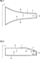
In
Die Drehanoden
Die in
Die Oberseite
Die in
Die Oberseite
Als Materialien für eine zumindest teilweise Oberflächenbeschichtung der Anode
Alternativ kann das Material für die Oberflächenbeschichtung der Anode
ZITATE ENTHALTEN IN DER BESCHREIBUNG QUOTES INCLUDE IN THE DESCRIPTION
Diese Liste der vom Anmelder aufgeführten Dokumente wurde automatisiert erzeugt und ist ausschließlich zur besseren Information des Lesers aufgenommen. Die Liste ist nicht Bestandteil der deutschen Patent- bzw. Gebrauchsmusteranmeldung. Das DPMA übernimmt keinerlei Haftung für etwaige Fehler oder Auslassungen.This list of the documents listed by the applicant has been generated automatically and is included solely for the better information of the reader. The list is not part of the German patent or utility model application. The DPMA assumes no liability for any errors or omissions.
Zitierte PatentliteraturCited patent literature
- US 7260181 B2 [0010, 0013] US 7260181 B2 [0010, 0013]
- US 2009/0279669 A1 [0013] US 2009/0279669 A1 [0013]
- US 2008/0112538 A1 [0020] US 2008/0112538 A1 [0020]
- US 2010/0046716 A1 [0021] US 2010/0046716 A1 [0021]
- US 4352196 A1 [0022] US Pat. No. 4,352,196 A1 [0022]
- DE 19914825 A1 [0023] DE 19914825 A1 [0023]
- WO 2008/090518 A1 [0024] WO 2008/090518 A1 [0024]
- US 5199059 A1 [0025] US 5199059 A1 [0025]
Zitierte Nicht-PatentliteraturCited non-patent literature
- Kanaya K, Okayama S., ”Penetration and energy-loss theory of electrons in solid targets”, J. Phys. D: Appl. Phys., Vol. 5, 1972, pp. 43–58 [0011] Kanaya K, Okayama S., "Penetration and energy-loss theory of electrons in solid targets", J. Phys. D: Appl. Phys., Vol. 5, 1972, pp. 43-58 [0011]
Claims (17)
Priority Applications (1)
| Application Number | Priority Date | Filing Date | Title |
|---|---|---|---|
| DE102010040407A DE102010040407A1 (en) | 2010-09-08 | 2010-09-08 | X-ray tube, has anode partially comprising surface coatings provided outside stopping area of focal spot, where surface coatings are made of material with nuclear charge number less than nuclear charge number of material of anode |
Applications Claiming Priority (1)
| Application Number | Priority Date | Filing Date | Title |
|---|---|---|---|
| DE102010040407A DE102010040407A1 (en) | 2010-09-08 | 2010-09-08 | X-ray tube, has anode partially comprising surface coatings provided outside stopping area of focal spot, where surface coatings are made of material with nuclear charge number less than nuclear charge number of material of anode |
Publications (1)
| Publication Number | Publication Date |
|---|---|
| DE102010040407A1 true DE102010040407A1 (en) | 2012-03-08 |
Family
ID=45595341
Family Applications (1)
| Application Number | Title | Priority Date | Filing Date |
|---|---|---|---|
| DE102010040407A Withdrawn DE102010040407A1 (en) | 2010-09-08 | 2010-09-08 | X-ray tube, has anode partially comprising surface coatings provided outside stopping area of focal spot, where surface coatings are made of material with nuclear charge number less than nuclear charge number of material of anode |
Country Status (1)
| Country | Link |
|---|---|
| DE (1) | DE102010040407A1 (en) |
Citations (12)
| Publication number | Priority date | Publication date | Assignee | Title |
|---|---|---|---|---|
| US4029828A (en) * | 1975-06-23 | 1977-06-14 | Schwarzkopf Development Corporation | X-ray target |
| US4352196A (en) | 1977-01-28 | 1982-09-28 | Compagnie Generale De Radiologie | X-Ray tube for producing a flat wide-angle fan-shaped beam of X-rays |
| US4516255A (en) * | 1982-02-18 | 1985-05-07 | Schwarzkopf Development Corporation | Rotating anode for X-ray tubes |
| US4637042A (en) * | 1980-04-18 | 1987-01-13 | The Machlett Laboratories, Incorporated | X-ray tube target having electron pervious coating of heat absorbent material on X-ray emissive surface |
| US4975621A (en) * | 1989-06-26 | 1990-12-04 | Union Carbide Corporation | Coated article with improved thermal emissivity |
| US5199059A (en) | 1990-11-22 | 1993-03-30 | Schwarzkopf Technologies Corporation | X-ray tube anode with oxide coating |
| DE19914825A1 (en) | 1999-03-31 | 2000-06-29 | Siemens Ag | Vacuum housing for an electron tube, especially a rotating-anode x-ray tube, has a metallic housing section with an interior high thermal absorption coefficient coating layer |
| US7260181B2 (en) | 2003-05-30 | 2007-08-21 | Koninklijke Philips Electronics, N.V. | Enhanced electron backscattering in x-ray tubes |
| US20080112538A1 (en) | 2006-11-09 | 2008-05-15 | General Electric Company | Electron absorption apparatus for an x-ray device |
| WO2008090518A1 (en) | 2007-01-26 | 2008-07-31 | Koninklijke Philips Electronics N.V. | Spectrum-preserving heel effect compensation filter made from the same material as anode plate |
| US20090279669A1 (en) | 2008-05-07 | 2009-11-12 | Donald Robert Allen | Apparatus for reducing kv-dependent artifacts in an imaging system and method of making same |
| US20100046716A1 (en) | 2008-08-20 | 2010-02-25 | Joerg Freudenberger | X-ray tube with backscatter protection |
-
2010
- 2010-09-08 DE DE102010040407A patent/DE102010040407A1/en not_active Withdrawn
Patent Citations (12)
| Publication number | Priority date | Publication date | Assignee | Title |
|---|---|---|---|---|
| US4029828A (en) * | 1975-06-23 | 1977-06-14 | Schwarzkopf Development Corporation | X-ray target |
| US4352196A (en) | 1977-01-28 | 1982-09-28 | Compagnie Generale De Radiologie | X-Ray tube for producing a flat wide-angle fan-shaped beam of X-rays |
| US4637042A (en) * | 1980-04-18 | 1987-01-13 | The Machlett Laboratories, Incorporated | X-ray tube target having electron pervious coating of heat absorbent material on X-ray emissive surface |
| US4516255A (en) * | 1982-02-18 | 1985-05-07 | Schwarzkopf Development Corporation | Rotating anode for X-ray tubes |
| US4975621A (en) * | 1989-06-26 | 1990-12-04 | Union Carbide Corporation | Coated article with improved thermal emissivity |
| US5199059A (en) | 1990-11-22 | 1993-03-30 | Schwarzkopf Technologies Corporation | X-ray tube anode with oxide coating |
| DE19914825A1 (en) | 1999-03-31 | 2000-06-29 | Siemens Ag | Vacuum housing for an electron tube, especially a rotating-anode x-ray tube, has a metallic housing section with an interior high thermal absorption coefficient coating layer |
| US7260181B2 (en) | 2003-05-30 | 2007-08-21 | Koninklijke Philips Electronics, N.V. | Enhanced electron backscattering in x-ray tubes |
| US20080112538A1 (en) | 2006-11-09 | 2008-05-15 | General Electric Company | Electron absorption apparatus for an x-ray device |
| WO2008090518A1 (en) | 2007-01-26 | 2008-07-31 | Koninklijke Philips Electronics N.V. | Spectrum-preserving heel effect compensation filter made from the same material as anode plate |
| US20090279669A1 (en) | 2008-05-07 | 2009-11-12 | Donald Robert Allen | Apparatus for reducing kv-dependent artifacts in an imaging system and method of making same |
| US20100046716A1 (en) | 2008-08-20 | 2010-02-25 | Joerg Freudenberger | X-ray tube with backscatter protection |
Non-Patent Citations (1)
| Title |
|---|
| Kanaya K, Okayama S., "Penetration and energy-loss theory of electrons in solid targets", J. Phys. D: Appl. Phys., Vol. 5, 1972, pp. 43-58 |
Similar Documents
| Publication | Publication Date | Title |
|---|---|---|
| EP2438212B1 (en) | X-ray tube with a backscattered electron shielded anode | |
| US8331535B2 (en) | Graphite backscattered electron shield for use in an X-ray tube | |
| DE102008038569A1 (en) | X-ray tube | |
| DE3303529C2 (en) | ||
| DE102008033150B4 (en) | X-ray source and mammography system and X-ray system with such an X-ray source | |
| EP3685420B1 (en) | Mbfex tube | |
| DE2154888A1 (en) | ROENTINE PIPE | |
| TW201638985A (en) | Composite target and X-ray tube with the composite target | |
| DE112023000574B4 (en) | MICROFOCUS X-RAY SOURCE FOR THE GENERATION OF HIGH FLUENT, LOW ENERGY X-RAY | |
| DE4230047C1 (en) | X-ray tube | |
| DE102010022595B4 (en) | X-ray tube with backscatter electron catcher | |
| DE202022104696U1 (en) | Target structure for generating X-rays | |
| DE102010040407A1 (en) | X-ray tube, has anode partially comprising surface coatings provided outside stopping area of focal spot, where surface coatings are made of material with nuclear charge number less than nuclear charge number of material of anode | |
| EP3742469A1 (en) | X-ray anode, x-ray emitter and method for producing an x-ray anode | |
| DE102006024437B4 (en) | X-ray | |
| DE102008014897A1 (en) | X-ray tube for use in industrial fine focus and micro-focus computer tomography, has transmission anode and X-ray discharge window, where transmission anode is arranged at X-ray discharge window | |
| EP2979293A1 (en) | X-ray source and imaging system | |
| DE69017877T2 (en) | X-ray rotating anode. | |
| DE102004025997A1 (en) | Device for generating and emitting XUV radiation | |
| DE102008032995A1 (en) | X-ray tube, has vacuum housing in which cathode and anode are arranged, where housing has inner wall that partially exhibits inertization, anode partially exhibits inertization and inertization comprises barrier layers | |
| DE102010030713B4 (en) | X-ray source for generating X-rays with a hollow body target and a method for generating X-radiation in a hollow body target | |
| EP0104515A2 (en) | High power rotary X-ray tube anode and method for its production | |
| DE102014204112A1 (en) | X-ray tube | |
| DE19900467A1 (en) | High power rotary anode X-ray tube | |
| DE102009033607A1 (en) | X-ray tube and anode for an X-ray tube |
Legal Events
| Date | Code | Title | Description |
|---|---|---|---|
| R002 | Refusal decision in examination/registration proceedings | ||
| R119 | Application deemed withdrawn, or ip right lapsed, due to non-payment of renewal fee |
Effective date: 20130403 |