DE102010029236B4 - External handle device for a vehicle door - Google Patents
External handle device for a vehicle door Download PDFInfo
- Publication number
- DE102010029236B4 DE102010029236B4 DE201010029236 DE102010029236A DE102010029236B4 DE 102010029236 B4 DE102010029236 B4 DE 102010029236B4 DE 201010029236 DE201010029236 DE 201010029236 DE 102010029236 A DE102010029236 A DE 102010029236A DE 102010029236 B4 DE102010029236 B4 DE 102010029236B4
- Authority
- DE
- Germany
- Prior art keywords
- engagement
- vehicle door
- outside
- base element
- actuated position
- Prior art date
- Legal status (The legal status is an assumption and is not a legal conclusion. Google has not performed a legal analysis and makes no representation as to the accuracy of the status listed.)
- Expired - Fee Related
Links
Images


Classifications
-
- E—FIXED CONSTRUCTIONS
- E05—LOCKS; KEYS; WINDOW OR DOOR FITTINGS; SAFES
- E05B—LOCKS; ACCESSORIES THEREFOR; HANDCUFFS
- E05B85/00—Details of vehicle locks not provided for in groups E05B77/00 - E05B83/00
- E05B85/10—Handles
- E05B85/14—Handles pivoted about an axis parallel to the wing
-
- E—FIXED CONSTRUCTIONS
- E05—LOCKS; KEYS; WINDOW OR DOOR FITTINGS; SAFES
- E05B—LOCKS; ACCESSORIES THEREFOR; HANDCUFFS
- E05B17/00—Accessories in connection with locks
- E05B17/14—Closures or guards for keyholes
- E05B17/18—Closures or guards for keyholes shaped as lids or slides
-
- E—FIXED CONSTRUCTIONS
- E05—LOCKS; KEYS; WINDOW OR DOOR FITTINGS; SAFES
- E05B—LOCKS; ACCESSORIES THEREFOR; HANDCUFFS
- E05B77/00—Vehicle locks characterised by special functions or purposes
- E05B77/34—Protection against weather or dirt, e.g. against water ingress
-
- Y—GENERAL TAGGING OF NEW TECHNOLOGICAL DEVELOPMENTS; GENERAL TAGGING OF CROSS-SECTIONAL TECHNOLOGIES SPANNING OVER SEVERAL SECTIONS OF THE IPC; TECHNICAL SUBJECTS COVERED BY FORMER USPC CROSS-REFERENCE ART COLLECTIONS [XRACs] AND DIGESTS
- Y10—TECHNICAL SUBJECTS COVERED BY FORMER USPC
- Y10T—TECHNICAL SUBJECTS COVERED BY FORMER US CLASSIFICATION
- Y10T292/00—Closure fasteners
- Y10T292/57—Operators with knobs or handles
-
- Y—GENERAL TAGGING OF NEW TECHNOLOGICAL DEVELOPMENTS; GENERAL TAGGING OF CROSS-SECTIONAL TECHNOLOGIES SPANNING OVER SEVERAL SECTIONS OF THE IPC; TECHNICAL SUBJECTS COVERED BY FORMER USPC CROSS-REFERENCE ART COLLECTIONS [XRACs] AND DIGESTS
- Y10—TECHNICAL SUBJECTS COVERED BY FORMER USPC
- Y10T—TECHNICAL SUBJECTS COVERED BY FORMER US CLASSIFICATION
- Y10T70/00—Locks
- Y10T70/80—Parts, attachments, accessories and adjuncts
- Y10T70/8432—For key-operated mechanism
- Y10T70/8649—Keyhole covers
Abstract
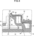
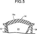
Außengriffvorrichtung für eine Fahrzeugtür, worin eine einwärts vertiefte Aufnahmevertiefung (23) in einem an einer Fahrzeugtür (11) zu befestigenden Basiselement (13) vorgesehen ist, wobei ein einen Betätigungsabschnitt (14a) aufweisender Außengriff (14) an dem Basiselement (13) schwenkbar gelagert ist, während er durch Zug an dem Betätigungsabschnitt (14a) in eine betätigte Stellung verschwenkbar ist und zur nicht betätigten Stellung hin federnd vorgespannt ist, wobei zumindest ein Teil des Betätigungsabschnitts (14a) in der Aufnahmevertiefung (23) angeordnet ist, und ein Zylinderschloss (15) an dem Basiselement (13) so angebracht ist, dass ein Schlüsselloch (23) zumindest in einem Zustand abgedeckt ist, in dem der Außengriff (14) in der nicht betätigten Stellung ist. In dem Außengriff ist ein Deckelelement (24) an dem Basiselement (13) abnehmbar so angebracht, dass es das Schlüsselloch (32) verdeckt, wobei das Deckelelement (24) als von dem Außengriff (14) separater Körper ausgebildet ist, so dass es Teil der Aufnahmevertiefung (23) bildet, während es eine Designfläche des Basiselements (13) bildet. Dementsprechend ist es möglich, eine Außengriffvorrichtung für eine Fahrzeugtür anzugeben, die eine Identifikation der Lage eines Zylinderschlosses erschwert.An outside handle device for a vehicle door, wherein an inwardly recessed receiving recess (23) is provided in a base member (13) to be fixed to a vehicle door (11), and an outside handle (14) having an operation portion (14a) is pivotally supported on the base member (13) while being pivotable to an actuated position by pulling on the operating portion (14a) and resiliently biased to the non-actuated position, at least a portion of the operating portion (14a) being disposed in the receiving recess (23), and a cylinder lock (Fig. 15) is mounted on the base member (13) so as to cover a keyhole (23) at least in a state in which the outer handle (14) is in the non-actuated position. In the outer handle, a lid member (24) is removably attached to the base member (13) so as to conceal the keyhole (32), the lid member (24) being formed as a separate body from the outer handle (14) so as to be part the receiving recess (23) forms while it forms a design surface of the base member (13). Accordingly, it is possible to provide an outside handle device for a vehicle door, which makes it difficult to identify the position of a cylinder lock.
Description
Die Erfindung betrifft eine Außengriffvorrichtung für eine Fahrzeugtür, worin eine einwärts vertiefte Aufnahmevertiefung in einem an einer Fahrzeugtür zu befestigenden Basiselement vorgesehen ist, wobei ein einen Betätigungsabschnitt aufweisender Außengriff an dem Basiselement schwenkbar gelagert ist, während durch Zug an dem Betätigungsabschnitt in eine betätigte Stellung verschwenkbar ist und zu einer nicht betätigten Stellung hin federnd vorgespannt ist, wobei zumindest ein Teil des Betätigungsabschnitts in der Aufnahmevertiefung angeordnet ist, und ein Zylinderschloss an dem Basiselement so angebracht ist, dass ein Schlüsselloch zumindest in einem Zustand abgedeckt ist, in dem der Außengriff in der nicht betätigten Stellung ist.The invention relates to an outer handle device for a vehicle door, wherein an inwardly recessed receiving recess is provided in a base member to be fastened to a vehicle door, wherein an outer handle having an operating portion is pivotally supported on the base member while being pivotable by pulling on the operating portion in an actuated position and is resiliently biased to a non-actuated position, wherein at least a portion of the actuating portion is disposed in the receiving recess, and a cylinder lock is attached to the base member so that a keyhole is covered at least in a state in which the outer handle in the non actuated position.
Aus der
Da jedoch in der Anordnung der
Aufgabe der Erfindung ist es daher, eine Außengriffvorrichtung für eine Fahrzeugtür anzugeben, welche die Identifikation der Lage eines Zylinderschlosses erschwert.The object of the invention is therefore to provide an external handle device for a vehicle door, which makes it difficult to identify the position of a cylinder lock.
Zur Lösung der Aufgabe wird, gemäß einem ersten Merkmal der Erfindung, eine Außengriffvorrichtung für eine Fahrzeugtür angegeben, worin eine einwärts vertiefte Aufnahmevertiefung in einem an einer Fahrzeugtür zu befestigenden Basiselement vorgesehen ist, wobei ein einen Betätigungsabschnitt aufweisender Außengriff an dem Basiselement schwenkbar gelagert ist, während er durch Zug an dem Betätigungsabschnitt in eine betätigte Stellung verschwenkbar ist und zu einer nicht betätigten Stellung hin federnd vorgespannt ist, wobei zumindest ein Teil des Betätigungsabschnitts in der Aufnahmevertiefung angeordnet ist, und ein Zylinderschloss an dem Basiselement so angebracht ist, dass ein Schlüsselloch zumindest in einem Zustand abgedeckt ist, in dem der Außengriff in der nicht betätigten Stellung ist, dadurch gekennzeichnet, dass ein Deckelelement an dem Basiselement so abnehmbar angebracht ist, dass es das Schlüsselloch verdeckt, wobei das Deckelelement als von dem Außengriff separater Körper ausgebildet ist, und Teil der Aufnahmevertiefung bildet, während es eine Designfläche oder Verkleidung des Basiselements bildet.To achieve the object, according to a first aspect of the invention, there is provided an outside handle device for a vehicle door, wherein an inwardly recessed receiving recess is provided in a base member to be fixed to a vehicle door, wherein an outside handle having an operation portion is pivotally supported on the base member it is pivotable by train on the actuating portion in an actuated position and is resiliently biased to a non-actuated position, wherein at least a portion of the actuating portion is disposed in the receiving recess, and a cylinder lock is attached to the base member so that a keyhole at least in is covered in a state in which the outer handle is in the non-actuated position, characterized in that a lid member is removably attached to the base member so as to conceal the keyhole, wherein the lid member as from the Außengri Separate body is formed, and forms part of the receiving recess, while forming a design surface or lining of the base member.
Da gemäß diesem ersten Merkmal der Erfindung das Deckelelement ein vom Außengriff separater Körper ist und an dem Basiselement abnehmbar angebracht ist, liegt, bei Betätigung des Außengriffs, das Schlüsselloch des Zylinderschlosses nicht nach außen frei. Da ferner das Deckelelement eine Designfläche des Basiselements bildet, lässt es sich, bei Betrachtung von der Außenseite der Fahrzeugtür, nur schwer als Deckelelement erkennen. Weil es ferner schwierig ist, die Stellung des Schlüsselloches zu identifizieren, erhält man eine ausgezeichnete Diebstahlsicherheit.According to this first feature of the invention, since the lid member is a body separate from the outer handle and detachably attached to the base member, the keyhole of the cylinder lock is not exposed to outside when the outer handle is operated. Further, since the lid member forms a design surface of the base member, it is difficult to recognize as a lid member when viewed from the outside of the vehicle door. Further, because it is difficult to identify the position of the keyhole, an excellent theft security is obtained.
Gemäß einem zweiten bevorzugten Merkmal sind der Betätigungsabschnitt und das Deckelelement, das an dem Basiselement durch Druck gegen eine Außenfläche des Basiselements abnehmbar angebracht ist, so ausgebildet, dass der Betätigungsabschnitt und ein Teil des Deckelelements bei Betrachtung von der Außenseite der Fahrzeugtür einander überlappen, so dass sich in einem Zustand, in dem der Außengriff in der nicht betätigten Stellung ist, sich der Betätigungsabschnitt von der Außenseite her gegen das Deckelelement abstützt.According to a second preferred feature, the operating portion and the lid member detachably attached to the base member by pressure against an outer surface of the base member are formed so that the operation portion and a part of the lid member overlap each other when viewed from the outside of the vehicle door, so that In a state in which the outer handle is in the non-actuated position, the actuating portion is supported from the outside against the lid member.
Da gemäß dem bevorzugten zweiten Merkmal der Erfindung dann, wenn das Deckelelement an dem Basiselement angebracht ist, der Betätigungsabschnitt des Außengriffs, der zur nicht betätigten Stellung hin federnd vorgespannt ist, sich gegen das Deckelelement abstützt, kann, wenn der Außengriff in der nicht betätigten Stellung ist, das Deckelelement, welches durch Druck gegen die Außenfläche des Basiselements an diesem Basiselement montiert wird, an dem Basiselement zuverlässig angebracht werden.Since according to the preferred second feature of the invention, when the lid member is attached to the base member, the operating portion of the outer handle, which is resiliently biased to the non-actuated position, is supported against the lid member, when the outer handle in the non-actuated position is, the cover member, which is mounted by pressure against the outer surface of the base member to this base member, are reliably attached to the base member.
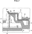
Gemäß einem bevorzugten dritten Merkmal der Erfindung ist ein Eingriffsloch in dem Basiselement vorgesehen, wobei ein Befestigungsvorsprung an dem Deckelelement so vorgesehen ist, dass er von der Außenseite der Fahrzeugtür her in das Eingriffsloch einsetzbar ist, wobei der Befestigungsvorsprung an seinem Außenende eine Eingriffsklaue aufweist, die mit einem inneren Endrand des Eingriffslochs in elastischen Eingriff treten kann, wobei Abschnitte eines Eingriffslösemittels, das einen Eingriffslösebetätigungsabschnitt aufweisen, der von einer Außenfläche des Basiselements vorsteht, und den Eingriff der Eingriffsklaue mit dem inneren Endrand des Eingrifflochs bei Betätigung des Eingriffslösebetätigungsabschnitts lösen kann, abgesehen von dem Eingriffslösebetätigungsabschnitt, an einer Innenseite des Basiselements angeordnet sind, und der Eingriffslösebetätigungsabschnitt an einer Position angeordnet ist, in der er in der nicht betätigten Position des Betätigungsabschnitts des Außengriffs abgedeckt ist.According to a preferred third feature of the invention, an engagement hole is in the A base member is provided, wherein a fastening projection is provided on the lid member so as to be inserted from the outside of the vehicle door into the engaging hole, the fastening projection having at its outer end an engaging claw which can resiliently engage an inner end edge of the engaging hole, wherein portions of engagement engagement means having an engagement engagement operation portion protruding from an outer surface of the base member and engagement of the engagement claw with the inner end edge of the engagement hole upon operation of the engagement engagement operation portion are disengaged except for the engagement engagement operation portion, on an inner side of the base member, and the engagement release operation portion is disposed at a position where it is covered in the non-actuated position of the operation portion of the outer handle.
Da gemäß dem bevorzugten dritten Merkmal der Erfindung das Deckelelement an dem Basiselement durch elastischen Eingriff montiert ist, wobei der innere Endrand des Eingriffslochs an dem Basiselement vorgesehen ist, wobei die Eingriffsklaue am Außenende des Befestigungsvorsprungs am Deckelelement so vorgesehen ist, dass sie von der Außenseite der Fahrzeugtür in das Eingriffsloch eingesetzt werden kann, und das Eingriffslösemittel den Eingriff der Eingriffsklaue am inneren Endrand des Eingriffsloch gemäß Betätigung des Eingriffslösebetätigungsabschnitts löst, wobei der Eingriffslösebetätigungsabschnitt an einer Position angeordnet ist, die von dem Betätigungsabschnitt des Außengriffs in der nicht betätigten Stellung verdeckt ist, lässt sich der Eingriffslösebetätigungsabschnitt nur in einem Zustand zu betätigen, in dem der Betätigungsabschnitt gezogen wird, um den Außengriff zur betätigten Stellung zu verschwenken, wodurch es schwierig gemacht wird, dass der Eingriffslösebetätigungsabschnitt unbefugt oder dergleichen betätigt wird.According to the third preferred feature of the invention, since the lid member is elastically engaged with the base member, the inner end edge of the engaging hole is provided on the base member, the engaging claw on the outer end of the fixing projection being provided on the lid member so as to project from the outer side of the lid member Vehicle door can be inserted into the engagement hole, and the engagement release means the engagement of the engagement claw at the inner end edge of the engagement hole according to actuation of the engagement release operating portion triggers, wherein the engagement release operating portion is disposed at a position which is covered by the operating portion of the outer handle in the non-actuated position leaves to operate the engagement release operation portion only in a state in which the operation portion is pulled to pivot the outer handle to the actuated position, whereby it is made difficult that the Eingri Unauthorized or the like is actuated so.
Gemäß einem bevorzugten vierten Merkmal der Erfindung umfasst das Eingriffslösemittel ein Druckelement, das sich gegen die Eingriffsklaue abstützen kann, so dass es auf die Eingriffsklaue gemäß Betätigung des Eingriffslösebetätigungsabschnitts eine Druckkraft in einer Richtung ausüben kann, die den Eingriff der Eingriffsklaue mit dem inneren Endrand des Eingriffslochs löst, und zumindest eine von Anlageflächen der Eingriffsklaue und des Druckelements als Schrägfläche ausgebildet ist, die die Druckkraft, die durch das Druckelement auf die Eingriffsklaue ausgeübt wird, in eine Kraft umwandelt, die den Befestigungsvorsprung zur Außenseite der Fahrzeugtür hin treibt.According to a preferred fourth aspect of the invention, the engagement releasing means comprises a pressing member that can be abutted against the engaging claw so that it can exert a pressing force on the engaging claw upon actuation of the engagement releasing operation portion in a direction that engages the engaging claw with the inner end edge of the engaging hole dissolves, and at least one of abutment surfaces of the engagement claw and the pressure member is formed as an inclined surface, which converts the pressing force exerted by the pressure element on the engagement claw into a force that drives the attachment projection to the outside of the vehicle door.
Da gemäß dem vierten bevorzugten Merkmal der Erfindung der Eingriff der Eingriffsklaue mit dem inneren Endrand des Eingriffslochs durch das Druckelement des Eingriffslösemittels gelöst wird, welches sich gegen die Eingriffsklaue abstützt und eine Druckkraft auf die Eingriffsklaue ausübt, wobei zumindest eine der Stützflächen der Eingriffsklaue und des Druckelements als Schrägfläche ausgebildet ist, und die Druckkraft, die von dem Druckelement auf die Eingriffsklaue wirkt, in eine Kraft umgewandelt wird, die den Befestigungsvorsprung zur Außenseite der Fahrzeugtür treibt, lässt sich das Deckelelement leicht von dem Basiselement abnehmen.According to the fourth preferred feature of the invention, the engagement of the engagement claw with the inner end edge of the engagement hole is released by the pressure member of the engagement solvent, which is supported against the engagement claw and applies a pressing force to the engagement claw, at least one of the support surfaces of the engagement claw and the pressure member is formed as an inclined surface, and the pressing force acting from the pressing member on the engaging claw is converted into a force that drives the fastening projection to the outside of the vehicle door, the lid member can be easily removed from the base member.
Die obigen Merkmale und andere Ziele, Charakteristika und Vorteile der Erfindung werden aus der folgenden detaillierten Beschreibung von bevorzugten Ausführungsbeispielen in Bezug auf die beigefügten Zeichnungen ersichtlich.The above features and other objects, features and advantages of the invention will be apparent from the following detailed description of preferred embodiments with reference to the accompanying drawings.
Nachfolgend wird ein Ausführungsbeispiel der Erfindung in Bezug auf die
Das Außenblech
Der Außengriff
Ein elastisches Element
Ferner wird der Außengriff
Ein Paar von Vorsprüngen
Ferner in Bezug auf
Darüber hinaus sind das Deckelelement
Ferner ist das Zylinderschloss
Der elastische Eingriff der Eingriffsklaue
Im Bezug auf
Wenn der Eingriffslösebetätigungsabschnitt
Darüber hinaus ist zumindest eine der Anlageflächen
Nachfolgend wird der Betrieb dieser Ausführung erläutert. Sobald das Deckelelement
Da ferner der Betätigungsabschnitt
Da ferner das Eingriffsloch
Da ferner das Eingriffslösemittel
Außengriffvorrichtung für eine Fahrzeugtür, worin eine einwärts vertiefte Aufnahmevertiefung (
Claims (4)
Applications Claiming Priority (2)
| Application Number | Priority Date | Filing Date | Title |
|---|---|---|---|
| JP2009-122779 | 2009-05-21 | ||
| JP2009122779A JP5064440B2 (en) | 2009-05-21 | 2009-05-21 | Outdoor handle device for vehicle door |
Publications (2)
| Publication Number | Publication Date |
|---|---|
| DE102010029236A1 DE102010029236A1 (en) | 2011-09-15 |
| DE102010029236B4 true DE102010029236B4 (en) | 2013-03-21 |
Family
ID=43102102
Family Applications (1)
| Application Number | Title | Priority Date | Filing Date |
|---|---|---|---|
| DE201010029236 Expired - Fee Related DE102010029236B4 (en) | 2009-05-21 | 2010-05-21 | External handle device for a vehicle door |
Country Status (4)
| Country | Link |
|---|---|
| US (1) | US8359712B2 (en) |
| JP (1) | JP5064440B2 (en) |
| CN (1) | CN101892768B (en) |
| DE (1) | DE102010029236B4 (en) |
Families Citing this family (10)
| Publication number | Priority date | Publication date | Assignee | Title |
|---|---|---|---|---|
| JP5727744B2 (en) * | 2010-09-30 | 2015-06-03 | 株式会社アルファ | Vehicle door inside handle device |
| JP5513442B2 (en) | 2011-05-27 | 2014-06-04 | 株式会社ホンダロック | Outdoor handle device for vehicle door |
| JP5950382B2 (en) * | 2011-11-29 | 2016-07-13 | マツダ株式会社 | Door handle device |
| US9593514B2 (en) * | 2013-02-18 | 2017-03-14 | Ford Global Technologies, Llc | Seamless exterior handle for a vehicle door |
| JP6130341B2 (en) * | 2014-10-10 | 2017-05-17 | 本田技研工業株式会社 | Vehicle door structure |
| EP3020895B1 (en) | 2014-11-13 | 2017-11-15 | Huf Hülsbeck & Fürst GmbH & Co. KG | Handle for a vehicle with a pulling device |
| JP6636851B2 (en) * | 2016-04-22 | 2020-01-29 | アイシン精機株式会社 | Inside handle support for vehicle doors |
| JP6612686B2 (en) * | 2016-06-21 | 2019-11-27 | 株式会社ホンダロック | Outdoor handle device for vehicle door |
| CN108533100A (en) * | 2018-05-11 | 2018-09-14 | 中山市澳多电子科技有限公司 | A kind of touch sensible concealed electric door handle |
| JP6651585B1 (en) * | 2018-08-30 | 2020-02-19 | 株式会社ホンダロック | Out-handle device for vehicle door |
Citations (5)
| Publication number | Priority date | Publication date | Assignee | Title |
|---|---|---|---|---|
| JPH0643383Y2 (en) * | 1988-02-01 | 1994-11-14 | 株式会社ユーシン | Door handle device with built-in cylinder lock |
| JPH11241532A (en) * | 1998-02-24 | 1999-09-07 | Yuhshin Co Ltd | Door opening handle |
| JP2002295063A (en) * | 2001-03-29 | 2002-10-09 | Honda Lock Mfg Co Ltd | Out steering wheel device of vehicle |
| JP2008088669A (en) * | 2006-09-29 | 2008-04-17 | Alpha Corp | Door handle device of automobile |
| JP2008248635A (en) * | 2007-03-30 | 2008-10-16 | Alpha Corp | Handle unit |
Family Cites Families (16)
| Publication number | Priority date | Publication date | Assignee | Title |
|---|---|---|---|---|
| US2070955A (en) * | 1935-11-25 | 1937-02-16 | Parisoe John | Handle and lock cover |
| US2217730A (en) * | 1937-09-14 | 1940-10-15 | Ternstedt Mfg Co | Cap for an automobile outside door locking handle |
| US2247592A (en) * | 1939-02-09 | 1941-07-01 | George L Swift | Protective device |
| US2670623A (en) * | 1950-01-31 | 1954-03-02 | Haltenberger Jules | Motor vehicle door lock accessory |
| US2585331A (en) * | 1950-09-25 | 1952-02-12 | Martin V King | Automobile door handle and lock shield |
| US2658376A (en) * | 1950-10-09 | 1953-11-10 | Ray M Shank | Automobile door lock protector |
| JPS58222260A (en) * | 1982-06-15 | 1983-12-23 | 株式会社大井製作所 | Door handle apparatus for automobile |
| JPH076419Y2 (en) * | 1988-12-02 | 1995-02-15 | 株式会社東海理化電機製作所 | Keyless entry mechanism switch mounting structure for starting |
| JPH0643383A (en) | 1992-07-27 | 1994-02-18 | Fuji Xerox Co Ltd | Light deflector |
| JPH076419A (en) | 1993-06-18 | 1995-01-10 | Fujitsu Ltd | Magneto-optical recording medium |
| FR2789712B1 (en) * | 1999-02-12 | 2001-06-01 | Valeo Securite Habitacle | MOTOR VEHICLE OPENING HANDLE COMPRISING A LOCK CAP |
| JP4041656B2 (en) | 2001-03-02 | 2008-01-30 | 株式会社日立製作所 | Storage system and data transmission / reception method in storage system |
| JP2002295059A (en) * | 2001-03-29 | 2002-10-09 | Honda Lock Mfg Co Ltd | Out handle device of vehicle |
| JP4154309B2 (en) * | 2003-10-21 | 2008-09-24 | 株式会社ホンダロック | Vehicle door handle device |
| US7526936B2 (en) * | 2006-02-21 | 2009-05-05 | Magna Closures Inc. | Hidden key cylinder |
| JP2008196224A (en) * | 2007-02-14 | 2008-08-28 | Tokai Rika Co Ltd | Key cylinder cover structure |
-
2009
- 2009-05-21 JP JP2009122779A patent/JP5064440B2/en not_active Expired - Fee Related
-
2010
- 2010-04-07 US US12/755,536 patent/US8359712B2/en active Active
- 2010-05-07 CN CN2010101748702A patent/CN101892768B/en not_active Expired - Fee Related
- 2010-05-21 DE DE201010029236 patent/DE102010029236B4/en not_active Expired - Fee Related
Patent Citations (5)
| Publication number | Priority date | Publication date | Assignee | Title |
|---|---|---|---|---|
| JPH0643383Y2 (en) * | 1988-02-01 | 1994-11-14 | 株式会社ユーシン | Door handle device with built-in cylinder lock |
| JPH11241532A (en) * | 1998-02-24 | 1999-09-07 | Yuhshin Co Ltd | Door opening handle |
| JP2002295063A (en) * | 2001-03-29 | 2002-10-09 | Honda Lock Mfg Co Ltd | Out steering wheel device of vehicle |
| JP2008088669A (en) * | 2006-09-29 | 2008-04-17 | Alpha Corp | Door handle device of automobile |
| JP2008248635A (en) * | 2007-03-30 | 2008-10-16 | Alpha Corp | Handle unit |
Also Published As
| Publication number | Publication date |
|---|---|
| JP5064440B2 (en) | 2012-10-31 |
| DE102010029236A1 (en) | 2011-09-15 |
| US20100293753A1 (en) | 2010-11-25 |
| US8359712B2 (en) | 2013-01-29 |
| CN101892768B (en) | 2013-03-20 |
| JP2010270489A (en) | 2010-12-02 |
| CN101892768A (en) | 2010-11-24 |
Similar Documents
| Publication | Publication Date | Title |
|---|---|---|
| DE102010029236B4 (en) | External handle device for a vehicle door | |
| DE102005001607B4 (en) | Door locking device, door and door locking unit | |
| DE102009045872A1 (en) | Flush gripping device for a door of a vehicle | |
| DE112016006099T5 (en) | VEHICLE DOOR LOCK SYSTEM | |
| DE102014116421A1 (en) | Glove compartment for a motor vehicle | |
| DE102014100148A1 (en) | MOUNTING FEATURE FOR A MOTOR VEHICLE TRIM FAIRING | |
| DE112016006079T5 (en) | VEHICLE DOOR LOCK SYSTEM | |
| DE202011000362U1 (en) | Device for automatically opening or closing drawer compartments | |
| DE202012004005U1 (en) | Device for snap-fastening two elements with press attachment to an engagement surface | |
| DE102006054193A1 (en) | closing device | |
| DE102014116407B4 (en) | Glove compartment for vehicle | |
| EP2615227B1 (en) | Remote control key for a motor vehicle | |
| DE102007045177A1 (en) | locking device | |
| DE69732438T2 (en) | locking device | |
| DE202016106793U1 (en) | Percussion rotary hand tool | |
| DE102016216996A1 (en) | Connection device and method for unlocking the connection device | |
| DE102014115062A1 (en) | Door lock mechanism for a vehicle | |
| DE202009012250U1 (en) | Locking device for a glass door handle | |
| DE202010008707U1 (en) | Drive arrangement with locking function | |
| EP2354386B1 (en) | Safety latch device | |
| DE2355656C2 (en) | Electrical connector device | |
| DE102014115880A1 (en) | Push-button locking mechanism for a vehicle | |
| DE102014116349A1 (en) | door lock | |
| DE202008001884U1 (en) | Automatic unlocking device for pull-out rail | |
| DE102015120539A1 (en) | An automobile door handle |
Legal Events
| Date | Code | Title | Description |
|---|---|---|---|
| R079 | Amendment of ipc main class |
Free format text: PREVIOUS MAIN CLASS: E05B0001000000 Ipc: E05B0017180000 |
|
| R163 | Identified publications notified | ||
| R163 | Identified publications notified |
Effective date: 20120416 |
|
| R018 | Grant decision by examination section/examining division | ||
| R020 | Patent grant now final |
Effective date: 20130622 |
|
| R081 | Change of applicant/patentee |
Owner name: KABUSHIKI KAISHA HONDA LOCK, JP Free format text: FORMER OWNERS: KABUSHIKI KAISHA HONDA LOCK, MIYAZAKI, JP; HONDA MOTOR CO., LTD., TOKYO, JP |
|
| R082 | Change of representative |
Representative=s name: WEICKMANN & WEICKMANN PATENT- UND RECHTSANWAEL, DE |
|
| R119 | Application deemed withdrawn, or ip right lapsed, due to non-payment of renewal fee |